EP0831492A1 - Control circuit of an output buffer, particularly for a non-volatile memory device - Google Patents
Control circuit of an output buffer, particularly for a non-volatile memory device Download PDFInfo
- Publication number
- EP0831492A1 EP0831492A1 EP96830475A EP96830475A EP0831492A1 EP 0831492 A1 EP0831492 A1 EP 0831492A1 EP 96830475 A EP96830475 A EP 96830475A EP 96830475 A EP96830475 A EP 96830475A EP 0831492 A1 EP0831492 A1 EP 0831492A1
- Authority
- EP
- European Patent Office
- Prior art keywords
- control circuit
- signal
- circuit
- output
- delay
- Prior art date
- Legal status (The legal status is an assumption and is not a legal conclusion. Google has not performed a legal analysis and makes no representation as to the accuracy of the status listed.)
- Granted
Links
Images

Classifications
-
- G—PHYSICS
- G11—INFORMATION STORAGE
- G11C—STATIC STORES
- G11C7/00—Arrangements for writing information into, or reading information out from, a digital store
- G11C7/10—Input/output [I/O] data interface arrangements, e.g. I/O data control circuits, I/O data buffers
- G11C7/1051—Data output circuits, e.g. read-out amplifiers, data output buffers, data output registers, data output level conversion circuits
- G11C7/1057—Data output buffers, e.g. comprising level conversion circuits, circuits for adapting load
-
- G—PHYSICS
- G11—INFORMATION STORAGE
- G11C—STATIC STORES
- G11C7/00—Arrangements for writing information into, or reading information out from, a digital store
- G11C7/10—Input/output [I/O] data interface arrangements, e.g. I/O data control circuits, I/O data buffers
- G11C7/1051—Data output circuits, e.g. read-out amplifiers, data output buffers, data output registers, data output level conversion circuits
Definitions
- This invention relates to a control circuit of an output buffer.
- the invention relates to a control circuit of an output buffer, of the type which comprises a first input terminal receiving a first enable signal and a second input terminal receiving a second enable signal, as well as first and second output terminals to generate first and second partial enable signals to transfer discrete sets of data bits, said first and second input terminals being coupled to said first and second output terminals through a multiplexer.
- the invention is particularly, but not exclusively, concerned with a control circuit of an output buffer for a non-volatile memory device, and the description to follow will make reference to such an application for convenience of illustration only.
- non-volatile memory devices include two basic control terminals which receive a first enable signal, conventionally designated CE, and a second enable signal, designated OE.
- the first signal CE enables the memory device operation, while the second signal OE enables its communication to internal or external circuitry.
- the enable signals, CE and OE are utilized, for example, to control output lines of memory devices through output buffers which are in a "tristate" condition, that is a high impedance condition, regulated by the signal OE.
- the enable signals CE and OE are applied to such output buffers by specially provided control circuits.
- the control circuit drives the output buffer to the high impedance condition, thereby enabling the communication of external logics to internal circuitry of the memory device.
- the control circuit enables the output buffer to transmit to the outside of the memory device data stored in the inside.
- the signal CE sets an operation interval of the memory device, for example to read data which is transferred to the output lines only during the checking of programmed data for correctness, in the course of a programming phase.
- the signal CE functions as a signal enabling the checking of programmed data.
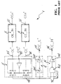
- FIG. 1 Shown schematically in Figure 1 is a control circuit 1' of an output buffer according to the prior art.
- the control circuit 1' includes first I1' and second I2' input terminals, as well as first O1' and second O2' output terminals.
- the first input terminal I1' receives the first enable signal OE', actually its negation OEn'
- the second input terminal I2' receives the second enable signal CE', actually its negation CEn'.
- the first input terminal I1' is further coupled to a first input terminal I3' of a multiplexer 2' through a first logic gate 3'.
- the second input terminal I2' is coupled to a second input terminal I4' of the multiplexer 2', through a second logic gate 4'.
- the multiplexer 2' has a further input terminal I5' receiving a control signal PG'.
- the multiplexer 2' also has an output terminal O3' which is coupled to both the first O1' and the second O2' output terminals of the control circuit 1', through respective logic circuits. In particular, first 5' and second 6' logic circuits are provided.
- the multiplexer 2' will choose between the first OE' and the second CE' enable signal according to the condition of operation of the memory device, that is, it will output the first enable signal OE' while reading of the memory device, the second enable signal CE' being only output during the memory device programming phase to enable the checking during the programming phase.
- the first logic circuit 5' comprises substantially first IN1' and second IN2' logic inverters connected in series with each other between the output terminal O3' of the multiplexer 2' and the first output terminal O1' of the control circuit 1'.
- the second logic circuit 6' similarly comprises a first logic gate PL1' with two inputs and of a third logic inverter IN3', connected in series with each other between the output terminal O3' of the multiplexer 2' and the second output terminal O2' of the control circuit 1'.
- said first logic gate PL1' receives a control signal WORD' at an input terminal I6'.
- the first O1' and second O2' output terminals of the control circuit 1 supply first OE_L' and second OE_H' partial enable signals which are advantageously utilized to control the transfer of discrete sets of bits.
- the enabling of the read data transfer to the output has a response time which is shorter than the propagation time required to complete the reading, from the time the memory is activated, which results in a first random switching of the output stages followed by a second reading, now a consistent one with the memory contents.
- the underlying technical problem of the present invention is to provide a control circuit of an output buffer, in particular for a non-volatile memory device, which has such structural and functional features as to allow the delaying of just the first switching of the memory device output lines at the end of a true reading interval, thereby overcoming the drawbacks with which prior art devices are beset.
- the idea of solution on which the present invention is based is to make the enabling of the output buffers to transmit read data dependent on a "first reading event", regardless of the generation of an enable signal.
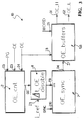
- FIG. 1 generally and schematically shown at 1 is a control circuit for an output buffer, according to this invention.
- the control circuit 1 includes first I1 and second I2 input terminals, and first O1 and second O2 output terminals.
- the first input terminal I1 receives a first enable signal OE, actually its negation OEn
- the second input terminal I2 receives the second enable signal CE, actually its negation CEn.
- circuit parts denoted by 2, 3 and 4 fully correspond to the circuit parts 2', 3' and 4' previously described with reference to Figure 1 and the prior art control circuit 1'.
- the multiplexer 2 has a first input terminal I3 receiving the first enable signal OE through a first logic gate 3, a second input terminal I4 receiving the second enable signal CE through a second logic gate 4, and a further input terminal I5 receiving a control signal PG.
- the multiplexer 2 also has an output terminal O3 coupled to the first O1 and second O2 output terminals of the control circuit 1 through respective first 5 and second 6 logic circuits and a synchronization circuit 7.
- the first logic circuit 5 comprises a first logic gate PL1 with two inputs, and a first logic inverter IN1, connected in series with each other between the output terminal O3 of the multiplexer 2 and the first output terminal O1 of the control circuit 1.
- the second logic circuit 6 comprises a second logic gate PL2 with three inputs, and a second logic inverter IN2, connected in series with each other between the output terminal O3 of the multiplexer 2 and the second output terminal O2 of the control circuit 1.
- said second logic gate PL2 receives a control signal WORD at another input terminal I6.
- the first PL1 and second PL2 logic gates have respective first I7 and second I8 input terminals in common.
- the second terminals I8 also receive the first enable signal OE.
- the logic gates PL1 and PL2 are of the NAND type.
- first O1 and second O2 output terminals of the control circuit 1 supply first OE_L and second OE_H partial enable signals which are used to control the transfer of discrete sets of bits.
- control circuit 1 also includes the synchronization circuit 7, connected to the output terminal O3 of the multiplexer 2 through a logic inverter IN3 and to the first common input terminal I7 of the logic circuits 5 and 6.
- the synchronization circuit 7 has a first input terminal I9 which is connected to the logic inverter IN3 and receives a disable signal DIS.
- the synchronization circuit 7 also has a second input terminal I10 receiving a synchronization signal SYNC.
- the circuit 7 has, moreover, an output terminal O4 for supplying a synchronized enable signal SYNC_OE of the pulse type.
- the synchronization circuit 7 simply comprises a flip-flop of the SET-RESET type.
- control circuit 1 The operation of the control circuit 1 according to the invention will now be described.
- the synchronization circuit 7 allows the partial enable signals OE_L and OE_H to be generated only on completion of a reading event.
- the synchronization signal SYNC indicates the simultaneous loading of data into the output buffers.
- the synchronized enable signal SYNC_OE goes to a high logic level, or 1 level, only upon the synchronization signal SYNC going to a 1 level, indicating the loading of data into the output buffers, thereby delaying the switching of the memory device outputs on completion of the reading, even when the enable signal OE has already been produced.
- the enable signal OE drives, to a low logic level or 0 level, the synchronization signal DIS, with no effects on propagation.
- the enable signal OE goes to a 1 level
- the synchronization signal DIS goes to a 0 level, thereby disabling the generation of the partial enable signals OE_L and OE_H and functioning, therefore, as a reset signal for the flip-flop 7.
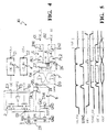
- the pattern sought for the output signal OUT is that shown in Figure 5.
- the disable pulse DIS should only be produced with the system disabled. Actually, the switching of the output lines may cause undesired pulses to appear in the pattern of the enable signals OE/CE which cause, in turn, incorrect pulses in the disable signal DIS. These incorrect pulses are shown by dash lines in Figure 5.
- the synchronized enable signal SYNC_OE goes to ground erroneously, causing the whole system to become disabled, through the partial enable signals OE_L and OE_H which are blocking the output buffers.
- a delay circuit has been purposely provided for the disable signal DIS.
- This delay circuit is incorporated to a modified embodiment of the inventive control circuit shown schematically in Figure 3.
- control circuit with an asymmetrical delay circuit 8 connected between the multiplexer 2 and the synchronization circuit 7.
- the delay circuit 8 shown in detail in Figure 4, is connected between a first supply voltage reference Vdd and a second voltage reference, in particular a signal ground GND, and connected to the output terminal O3 of the multiplexer 2 and to the input terminal I9 of the synchronization circuit 7.
- the delay circuit 8 has a control terminal I11 receiving a reference signal PCH_Icost and an output terminal O5 supplying a controlled disable signal DIS1 through the delay circuit 8.
- the delay circuit 8 should include an asymmetrical delay network, having a significant delay from a first edge of the enable signal OE and immediate natural propagation at a second edge of that signal.
- the delay circuit 8 comprises a charge control transistor P1 having a source terminal connected, through a first enable transistor P2, to the supply voltage reference Vdd, and a drain terminal connected to the ground GND through a parallel of a second enable transistor N1 and a delay capacitor C1.
- the charge control transistor P1 also has a gate terminal connected to the control terminal I11, while the enable transistors P2 and N1 have their gate terminals connected to the output terminal O3 of the multiplexer 2.
- the reference signal PCH_Icost cannot control, independently from the power supply, the conductivity of P1 such that the charging of the capacitor C1 can take place in a constant manner independently from the power supply.
- the charge control transistor P1 and the first enable transistor P2 are P-channel MOS transistors, whereas the second enable transistor N1 is an N-channel MOS transistor.
- the delay capacitor C1 is also connected to the input of a logic inverter IN4 which has its output connected to one input of a logic gate PL3, in particular a gate of the NOR type, having another input connected to the output terminal O3 of the multiplexer 2, and supplying the controlled disable signal DIS1 at its output terminal O5.
- the controlled disable signal DIS1 immediately goes to the 1 level, thereby allowing the enable signal OE to be propagated.
- the enable signal OE goes to a 0 level
- the controlled disable signal DIS1 goes to a 0 level only after the delay capacitor C1 is discharged.
- the controlled disable signal DIS1 immediately (or rather, after a trivial delay due to the switching of the logical elements included in the delay circuit 8) goes to a low logic level, or 0 level.
- the controlled disable signal DIS1 retains its 0 level until a charge current Icost, passing through the delay capacitor C1, brings the input of the logic inverter IN4 to a 1 level, and hence, the input of the logic gate PL3 to a 0 level, thus causing the output terminal O5 of the delay circuit 8 to go to a 1 level, and resetting the flip-flop 7.
- the switching of the controlled disable signal DIS1 at the falling edge of the enable signal OE occurs with a delay ⁇ t which allows the data reading cycle of the memory device to be completed.
- this delay is proportional to the charge current Icost of the delay capacitor C1 and is, therefore, independent from the supply voltage Vdd.
- control circuit 10 with delay circuit 8 according to the invention is of special advantage at high voltage levels, when the presence of high levels of noise disallows the use of known delay circuits for which the delay is proportional to the supply voltage.
- the operation of the delay circuit 8 incorporated to the control circuit 10 of this invention involves the use of a constant current generator capable of delivering a regulating signal PCH_Icost substantially constant with respect to the supply voltage Vdd.
- control circuit 10 with delay circuit 8 has immediate reaction features to the occurrence of a first reading cycle, and exhibits a delayed action from the disabling operation, thereby providing a filter action in the respect of pulses of noisy origin.
- the structures of the output buffers of memory devices operating at high voltages and equipped with this control circuit with delay can be safely increased in size to provide faster switchings, and accordingly, increased speed for the devices in their entirety.
- control circuit 1 and 10 of this invention can be used to synchronize the second enable signal CE, supplying it at the second common input terminal I8 of the logic circuits 5 and 6.
Abstract
Description
Claims (16)
- A control circuit (1) for an output buffer, of the type which comprises a first input terminal (I1) receiving a first enable signal (OEn) and a second input terminal (I2) receiving a second enable signal (CEn), as well as first (O1) and second (O2) output terminals to generate first (OE_L) and second (OE_H) partial enable signals to transfer discrete sets of data bits, said first (I1) and second (I2) input terminals being coupled to said first (O1) and second (O2) output terminals through a multiplexer (2), characterized in that it comprises a synchronization circuit (7) for linking the partial enable signals (OE_L,OE_H) operatively to a synchronization signal (SYNC) of the pulse type being synchronous with the loading of the output buffer, said synchronization circuit (7) being connected between an output terminal (O3) of said multiplexer (2) and the first (O1) and second (O2) output terminals of the control circuit (1).
- A control circuit (1) according to Claim 1, characterized in that the synchronization circuit (7) has a first input terminal (I10) receiving the synchronization signal (SYNC) and a second input terminal (I9), connected to the output terminal (O3) of the multiplexer (2), receiving a disable signal (DIS).
- A control circuit (10) according to Claim 2, characterized in that it comprises a delay circuit (8) connected between a first (Vdd) and a second (GND) voltage reference, and connected to the output terminal (O3) of the multiplexer (2) and to the second input terminal (I9) of the synchronization circuit (7), said delay circuit (8) having a control terminal (I11) receiving a reference signal (PCH_Icost) and an output terminal (O5) supplying the disable signal (DIS1).
- A control circuit (10) according to Claim 3, characterized in that the delay circuit (8) comprises an asymmetrical delay network having a significant delay from a first edge of an enable signal (OE/CE) and immediate natural propagation at a second edge of said signal.
- A control circuit (1) according to Claim 2, characterized in that the synchronization circuit (7) has an output terminal (O4) supplying a synchronized enable signal (SYNC_OE) to respective first common input terminals (I7) of first (5) and second (6) logic circuits being in turn connected to the first (O1) and the second (O2) output terminal of the control circuit (1).
- A control circuit (1) according to Claim 5, characterized in that the first (5) and second (6) logic circuits have further second common input terminals (I8) connected to an enable signal (OE/CE).
- A control circuit (10) according to Claim 4, characterized in that the asymmetrical delay network (8), being connected between a first (Vdd) and a second (GND) voltage reference and having an input terminal (I11) receiving a regulating signal (PCH_Icost), comprises at least a charge control transistor (P1) and a delay capacitor (C1) connected in series with each other between the first (Vdd) and second (GND) voltage references, said charge control transistor (P1) having a control terminal connected to the input terminal (I11), the asymmetrical delay network (8) having an output terminal (O5) supplying a controlled disable signal (DIS1) synchronized to a first edge of the enable signal (OE/CN).
- A control circuit (10) according to Claim 7, characterized in that the controlled disable signal (DIS1) switches from the first edge of the enable signal (OE/CN) with a delay (Δt) which is proportional to a charge or discharge time of the delay capacitor (C1) and substantially independent from the first voltage reference (Vdd), said signal also switching with no or trivial delay from a second edge of the enable signal (OE/CN).
- A control circuit (1) according to Claim 1, characterized in that said synchronization circuit (7) comprises essentially a flip-flop of the SET-RESET type.
- A control circuit (10) according to Claim 7, characterized in that the delay capacitor (C1) is connected to the output terminal (O5) by way of a series of first (IN4) and second (PL3) logic gates, said second logic gate (PL3) having an input terminal connected to the output terminal (O3) of the multiplexer (2).
- A control circuit (10) according to Claim 7, characterized in that it comprises first (P2) and second (N1) enable transistors, connected between the charge control transistor (P1) and the first (Vdd) and second (GND) voltage references, respectively, having a control terminal connected to the input terminal (I11) of the asymmetrical delay network (8).
- A control circuit (1) according to Claim 5, characterized in that the first (5) and second (6) logic circuits respectively comprise first (PL1,PL2) and second (IN1,IN2) logic gates connected in series with each other between the common input terminals (I7,I8) and the first (O1) and second (O2) output terminals of the control circuit (1).
- A control circuit (1) according to Claim 12, characterized in that said first logic gate (PL2) of the logic circuit (6) receives a control signal (WORD) at an input terminal (I6).
- A control circuit (1) according to Claim 1, characterized in that it comprises a logic gate (IN3) connected between the output terminal (O3) of the multiplexer (2) and the first (O1) and second (O2) output terminals of the control circuit (1).
- A method for a synchronous loading of data into an output buffer comprising a control circuit (1) receiving first (OEn) and second (CEn) enable signals and generating first (OE_L) and second (OE_H) partial enable signals to transfer data in discrete sets of bits, characterized in that it provides for the use of a synchronization signal (SYNC) of the pulse type which is synchronous with the output buffer loading and generated by a synchronization circuit (7) to control the partial enable signals (OE_L,OE_H).
- A synchronous data loading method according to Claim 15, characterized in that it provides a delay circuit (8), connected to said synchronization circuit (7), comprising an asymmetrical delay network which features an immediate reaction to the occurrence of a first data reading cycle and a delayed action with respect to a synchronization circuit (7) disabling operation, thereby producing a filtering action in the respect of pulses of noisy origin.
Priority Applications (3)
| Application Number | Priority Date | Filing Date | Title |
|---|---|---|---|
| DE69626815T DE69626815T2 (en) | 1996-09-19 | 1996-09-19 | Control circuit for output buffers, especially for a non-volatile memory arrangement |
| EP96830475A EP0831492B1 (en) | 1996-09-19 | 1996-09-19 | Control circuit of an output buffer, particularly for a non-volatile memory device |
| US08/934,499 US5905678A (en) | 1996-09-19 | 1997-09-19 | Control circuit of an output buffer |
Applications Claiming Priority (1)
| Application Number | Priority Date | Filing Date | Title |
|---|---|---|---|
| EP96830475A EP0831492B1 (en) | 1996-09-19 | 1996-09-19 | Control circuit of an output buffer, particularly for a non-volatile memory device |
Publications (2)
| Publication Number | Publication Date |
|---|---|
| EP0831492A1 true EP0831492A1 (en) | 1998-03-25 |
| EP0831492B1 EP0831492B1 (en) | 2003-03-19 |
Family
ID=8226008
Family Applications (1)
| Application Number | Title | Priority Date | Filing Date |
|---|---|---|---|
| EP96830475A Expired - Lifetime EP0831492B1 (en) | 1996-09-19 | 1996-09-19 | Control circuit of an output buffer, particularly for a non-volatile memory device |
Country Status (3)
| Country | Link |
|---|---|
| US (1) | US5905678A (en) |
| EP (1) | EP0831492B1 (en) |
| DE (1) | DE69626815T2 (en) |
Families Citing this family (3)
| Publication number | Priority date | Publication date | Assignee | Title |
|---|---|---|---|---|
| US6011749A (en) * | 1998-03-27 | 2000-01-04 | Motorola, Inc. | Integrated circuit having output timing control circuit and method thereof |
| US6438040B1 (en) * | 2000-07-31 | 2002-08-20 | Stmicroelectronics S.R.L. | Enabling circuit for output devices in electronic memories |
| JP4005909B2 (en) * | 2002-12-26 | 2007-11-14 | スパンション インク | Semiconductor memory device and method for controlling semiconductor memory device |
Citations (5)
| Publication number | Priority date | Publication date | Assignee | Title |
|---|---|---|---|---|
| EP0473127A2 (en) * | 1990-08-30 | 1992-03-04 | Kabushiki Kaisha Toshiba | Semiconductor integrated circuit |
| EP0534394A2 (en) * | 1991-09-27 | 1993-03-31 | Mitsubishi Denki Kabushiki Kaisha | Semiconductor memory device and method for controlling its output |
| US5307317A (en) * | 1990-07-05 | 1994-04-26 | Kabushiki Kaisha Toshiba | Semiconductor memory device having improved access to addresses |
| EP0624878A2 (en) * | 1987-12-28 | 1994-11-17 | Kabushiki Kaisha Toshiba | Semiconductor integrated circuit |
| DE4440169A1 (en) * | 1993-11-11 | 1995-05-18 | Hyundai Electronics Ind | Data output unit for semiconductor memory |
Family Cites Families (3)
| Publication number | Priority date | Publication date | Assignee | Title |
|---|---|---|---|---|
| US5268868A (en) * | 1987-09-16 | 1993-12-07 | Hitachi, Ltd. | Output buffer circuits for reducing ground bounce noise |
| US4825410A (en) * | 1987-10-26 | 1989-04-25 | International Business Machines Corporation | Sense amplifier control circuit |
| KR0169419B1 (en) * | 1995-09-28 | 1999-02-01 | 김광호 | Reading method and device of non-volatile semiconductor memory |
-
1996
- 1996-09-19 DE DE69626815T patent/DE69626815T2/en not_active Expired - Fee Related
- 1996-09-19 EP EP96830475A patent/EP0831492B1/en not_active Expired - Lifetime
-
1997
- 1997-09-19 US US08/934,499 patent/US5905678A/en not_active Expired - Lifetime
Patent Citations (5)
| Publication number | Priority date | Publication date | Assignee | Title |
|---|---|---|---|---|
| EP0624878A2 (en) * | 1987-12-28 | 1994-11-17 | Kabushiki Kaisha Toshiba | Semiconductor integrated circuit |
| US5307317A (en) * | 1990-07-05 | 1994-04-26 | Kabushiki Kaisha Toshiba | Semiconductor memory device having improved access to addresses |
| EP0473127A2 (en) * | 1990-08-30 | 1992-03-04 | Kabushiki Kaisha Toshiba | Semiconductor integrated circuit |
| EP0534394A2 (en) * | 1991-09-27 | 1993-03-31 | Mitsubishi Denki Kabushiki Kaisha | Semiconductor memory device and method for controlling its output |
| DE4440169A1 (en) * | 1993-11-11 | 1995-05-18 | Hyundai Electronics Ind | Data output unit for semiconductor memory |
Also Published As
| Publication number | Publication date |
|---|---|
| EP0831492B1 (en) | 2003-03-19 |
| US5905678A (en) | 1999-05-18 |
| DE69626815D1 (en) | 2003-04-24 |
| DE69626815T2 (en) | 2003-12-11 |
Similar Documents
| Publication | Publication Date | Title |
|---|---|---|
| US5604452A (en) | Clock generator using a state machine to switch between two offset clocks | |
| KR0164807B1 (en) | Data output buffer control circuit for semiconductor memory device | |
| US6111447A (en) | Timing circuit that selectively triggers on a rising or falling input signal edge | |
| JP3820559B2 (en) | Mode register set circuit of semiconductor device | |
| JPH0856149A (en) | Programmable logic array structure for nonvolatile memory ofsemiconductor,especially flash eprom | |
| US5124585A (en) | Pulsed bootstrapping output buffer and associated method | |
| US5198709A (en) | Address transition detector circuit | |
| JP3567601B2 (en) | Input / output buffer circuit and output buffer circuit | |
| USRE41441E1 (en) | Output buffer having inherently precise data masking | |
| EP0831492B1 (en) | Control circuit of an output buffer, particularly for a non-volatile memory device | |
| US6496443B2 (en) | Data buffer control circuits, integrated circuit memory devices and methods of operation thereof using read cycle initiated data buffer clock signals | |
| US5896341A (en) | Synchronous semiconductor memory circuit | |
| US6028448A (en) | Circuitry architecture and method for improving output tri-state time | |
| KR100211149B1 (en) | Control circuit of data output buffer in semiconductor memory device | |
| EP0333206B1 (en) | Semiconductor integrated circuit | |
| US6232797B1 (en) | Integrated circuit devices having data buffer control circuitry therein that accounts for clock irregularities | |
| JPH1173775A (en) | Output circuit of semiconductor memory device | |
| KR100316184B1 (en) | Auto-precharge controller | |
| US6075751A (en) | Signal transition detector for asynchronous circuits | |
| KR100389038B1 (en) | Synchronous sram device with late write function | |
| KR0119886B1 (en) | Mode set circuit and its method | |
| JP4278743B2 (en) | Semiconductor memory device | |
| KR960011208B1 (en) | Semiconductor memory device | |
| EP0915477B1 (en) | Method and circuit for generating an ATD signal to regulate the access to a non-volatile memory | |
| US11145353B1 (en) | Centralized DFE reset generator for a memory device |
Legal Events
| Date | Code | Title | Description |
|---|---|---|---|
| PUAI | Public reference made under article 153(3) epc to a published international application that has entered the european phase |
Free format text: ORIGINAL CODE: 0009012 |
|
| AK | Designated contracting states |
Kind code of ref document: A1 Designated state(s): DE FR GB IT |
|
| AX | Request for extension of the european patent |
Free format text: AL;LT;LV;SI |
|
| RAP3 | Party data changed (applicant data changed or rights of an application transferred) |
Owner name: STMICROELECTRONICS S.R.L. |
|
| 17P | Request for examination filed |
Effective date: 19980915 |
|
| AKX | Designation fees paid |
Free format text: DE FR GB IT |
|
| RBV | Designated contracting states (corrected) |
Designated state(s): DE FR GB IT |
|
| GRAG | Despatch of communication of intention to grant |
Free format text: ORIGINAL CODE: EPIDOS AGRA |
|
| 17Q | First examination report despatched |
Effective date: 20020527 |
|
| GRAG | Despatch of communication of intention to grant |
Free format text: ORIGINAL CODE: EPIDOS AGRA |
|
| GRAH | Despatch of communication of intention to grant a patent |
Free format text: ORIGINAL CODE: EPIDOS IGRA |
|
| GRAH | Despatch of communication of intention to grant a patent |
Free format text: ORIGINAL CODE: EPIDOS IGRA |
|
| GRAA | (expected) grant |
Free format text: ORIGINAL CODE: 0009210 |
|
| AK | Designated contracting states |
Designated state(s): DE FR GB IT |
|
| REG | Reference to a national code |
Ref country code: GB Ref legal event code: FG4D |
|
| REF | Corresponds to: |
Ref document number: 69626815 Country of ref document: DE Date of ref document: 20030424 Kind code of ref document: P |
|
| ET | Fr: translation filed | ||
| PLBE | No opposition filed within time limit |
Free format text: ORIGINAL CODE: 0009261 |
|
| STAA | Information on the status of an ep patent application or granted ep patent |
Free format text: STATUS: NO OPPOSITION FILED WITHIN TIME LIMIT |
|
| 26N | No opposition filed |
Effective date: 20031222 |
|
| PGFP | Annual fee paid to national office [announced via postgrant information from national office to epo] |
Ref country code: DE Payment date: 20040826 Year of fee payment: 9 |
|
| PG25 | Lapsed in a contracting state [announced via postgrant information from national office to epo] |
Ref country code: IT Free format text: LAPSE BECAUSE OF NON-PAYMENT OF DUE FEES;WARNING: LAPSES OF ITALIAN PATENTS WITH EFFECTIVE DATE BEFORE 2007 MAY HAVE OCCURRED AT ANY TIME BEFORE 2007. THE CORRECT EFFECTIVE DATE MAY BE DIFFERENT FROM THE ONE RECORDED. Effective date: 20050919 |
|
| PG25 | Lapsed in a contracting state [announced via postgrant information from national office to epo] |
Ref country code: DE Free format text: LAPSE BECAUSE OF NON-PAYMENT OF DUE FEES Effective date: 20060401 |
|
| PGFP | Annual fee paid to national office [announced via postgrant information from national office to epo] |
Ref country code: GB Payment date: 20080827 Year of fee payment: 13 |
|
| PGFP | Annual fee paid to national office [announced via postgrant information from national office to epo] |
Ref country code: FR Payment date: 20080929 Year of fee payment: 13 |
|
| GBPC | Gb: european patent ceased through non-payment of renewal fee |
Effective date: 20090919 |
|
| REG | Reference to a national code |
Ref country code: FR Ref legal event code: ST Effective date: 20100531 |
|
| PG25 | Lapsed in a contracting state [announced via postgrant information from national office to epo] |
Ref country code: FR Free format text: LAPSE BECAUSE OF NON-PAYMENT OF DUE FEES Effective date: 20090930 |
|
| PG25 | Lapsed in a contracting state [announced via postgrant information from national office to epo] |
Ref country code: GB Free format text: LAPSE BECAUSE OF NON-PAYMENT OF DUE FEES Effective date: 20090919 |