EP0833140A2 - Diagnostic system - Google Patents
Diagnostic system Download PDFInfo
- Publication number
- EP0833140A2 EP0833140A2 EP97307076A EP97307076A EP0833140A2 EP 0833140 A2 EP0833140 A2 EP 0833140A2 EP 97307076 A EP97307076 A EP 97307076A EP 97307076 A EP97307076 A EP 97307076A EP 0833140 A2 EP0833140 A2 EP 0833140A2
- Authority
- EP
- European Patent Office
- Prior art keywords
- integrated control
- control means
- vehicle
- diagnostic system
- information
- Prior art date
- Legal status (The legal status is an assumption and is not a legal conclusion. Google has not performed a legal analysis and makes no representation as to the accuracy of the status listed.)
- Withdrawn
Links
Images


Classifications
-
- H—ELECTRICITY
- H04—ELECTRIC COMMUNICATION TECHNIQUE
- H04L—TRANSMISSION OF DIGITAL INFORMATION, e.g. TELEGRAPHIC COMMUNICATION
- H04L12/00—Data switching networks
- H04L12/28—Data switching networks characterised by path configuration, e.g. LAN [Local Area Networks] or WAN [Wide Area Networks]
- H04L12/40—Bus networks
- H04L12/40052—High-speed IEEE 1394 serial bus
- H04L12/40117—Interconnection of audio or video/imaging devices
-
- F—MECHANICAL ENGINEERING; LIGHTING; HEATING; WEAPONS; BLASTING
- F02—COMBUSTION ENGINES; HOT-GAS OR COMBUSTION-PRODUCT ENGINE PLANTS
- F02B—INTERNAL-COMBUSTION PISTON ENGINES; COMBUSTION ENGINES IN GENERAL
- F02B77/00—Component parts, details or accessories, not otherwise provided for
- F02B77/08—Safety, indicating or supervising devices
-
- G—PHYSICS
- G01—MEASURING; TESTING
- G01M—TESTING STATIC OR DYNAMIC BALANCE OF MACHINES OR STRUCTURES; TESTING OF STRUCTURES OR APPARATUS, NOT OTHERWISE PROVIDED FOR
- G01M15/00—Testing of engines
- G01M15/04—Testing internal-combustion engines
- G01M15/05—Testing internal-combustion engines by combined monitoring of two or more different engine parameters
Definitions
- the present invention relates in general to test equipment and, more particularly, to diagnostic, test and information systems.
- the cables for example, include a cable that connects to the motor vehicle battery and another cable that connects to an electrical system or component of the motor vehicle to measure voltage and current, as well as a data cable that connects to the engine control module to transmit information about operation of the vehicle to the hand held tester or to enable the tester to control various motor vehicle functions. See, for example, Tech 1, “Cartridges and Accessories," September, 1989.
- the cables connected to the motor vehicle are typically heavy and stiff. Consequently, the hand held tester is unweildly to operate, which is inconvenient to the user. Furthermore, the display screen on the hand held tester is small, and therefore, only a minimal amount of information can be displayed to the user.
- the trend in the motor vehicle service bay is toward greater access to information relating to maintenance and repair. This trend requires the user to have a larger display screen incorporated into his or her test equipment and many connections to the motor vehicle, as well as to a dealership local area network (LAN).
- LAN local area network
- motor vehicle manufacturers have provided printed information regarding maintenance and repair. As a service to motor vehicle maintenance and repair personnel, the manufacturers provided published information, such as manuals, for reference during maintenance and repair of motor vehicles. However, published information requires a large amount of storage space. More recently, motor vehicle manufacturers have provided maintenance and repair information on microfiche which is periodically updated. Although microfiche reduces storage requirements, microfiche can be misfiled and microfiche readers are cumbersome to use.
- the TestBook system is a portable integrated personal computer and test system that provides compact mobile test and information tool for use in the motor vehicle service bay or on a road test.
- the TestBook system comprises a 486-microprocessor-based person computer, an integrated adjustable VGA liquid crystal display (LCD) panel and touchscreen interactive user interface having a capacitative touch-activated screen, and a built-in CD-ROM drive to provide faster and easier access to the latest service procedures and information for maintenance and repair of a motor vehicle.
- Built-in measure instrumentation and a programmable communications interface offer a test capability for computer-aided diagnostic applications.
- the TestBook system can be custom-configured to meet various MS-DOS, Windows, or OS/2 application requirements.
- TestBook system provides ready access to a large amount of information needed for maintenance and repair of a motor vehicle
- cables that connect to the vehicle must be attached to the measurement instrumentation integrated into the system. Consequently, as in the case of hand held testers, the TestBook system is unwieldy and is typically set on a work surface, such as a workbench or tool chest, during use. Therefore, the user does not have ready access to the integrated interactive display of the TestBook system while he or she is under the hood of the motor vehicle.
- test and information tool for maintenance and repair of a motor vehicle which, has a selectively detachable, remotely operated interactive display unit that controls a portable integrated personal computer and test system is disclosed in co-pending U.S. Patent Application Series Code/Serial No. 08/421,591, filed on April 5, 1995 and assigned to the same assignee as the present application.
- This motor vehicle test and information tool provides greater user mobility than the TestBook system, because the display unit is not encumbered by being integrated with the personal computer having the additional weight of measurement instrumentation tethered by cables connected to electrical systems and components, as well as the engine control module, of the motor vehicle.
- the measurement instrumentation is integrated with the personal computer, which requires a specially designed housing to accommodate both the personal computer and measurement instrumentation.
- the integrated personal computer and measurement instrumentation must also meet environmental and safety requirements relating to test equipment used in a motor vehicle service bay.
- a modular wireless diagnostic, test and information system comprising a combined user interface and main control module and at least one remotely controlled instrumentation module connected by wireless communication is disclosed in co-pending U.S. Patent Application Series Code/Serial No. 08/504,935, filed on 07/20/95 and assigned to the same assignee as the present application.
- the combined user interface with main control module has an interactive display which enables the user to command the functions of the remotely deployed instrumentation module(s) and enter data through interaction with the display, as well as execute application programs and displays information to the user.
- one embodiment of the invention provides a combined user interface and main control module while having an interactive display, in which the user interacts with the display to access complex technical information employed to maintain and repair a motor vehicle and to control the instrumentation module(s) over a wireless communication link in the form of a radio-frequency (RF) local area network (LAN) to perform measurements on the vehicle, as well as to execute diagnostic routines and to display information to the user.
- RF radio-frequency
- LAN local area network
- wireless test diagnostic system facilitate movement and positioning of the vehicle instrumentation modules and user interface
- the wireless LAN circuitry and hardware components required to implement the wireless test diagnostic system are expensive.
- this increase in cost does not come with an increase in system performance.
- a disadvantage of wireless test diagnostic system is that the data being transferred from the instrumentation modules to the master control module has a slow data transfer rate.
- typical data transfer rates for a wireless system would be 2MB/sec. While this data transfer rate is sufficient for instrumentation channels having a slow data transfer rate, this data transfer rate may be insufficient for multiple vehicle instrumentation modules which have high speed data channels.
- wireless communications systems are less reliable than traditional test diagnostic systems.
- applications programs will often run on the server sending data to the user interface via the wireless LAN circuitry. This is problematic if the network goes down since failure of the network results in the wireless test diagnostic system being unable to communicate with the server. Further, because the applications programs are stored on the server, network failure would prevent the technician from operating the wireless test diagnostic system locally.
- wireless systems are more prone to failure due to their increased susceptibility to radio noise. Unfortunately, this problem is likely to increase due to the increased utilization of carrier frequency bands with wireless appliances such as cellular phone, etc.
- the present invention seeks to provide an improved vehicle diagnostic system.
- the preferred embodiment provides an inexpensive, automobile test diagnostic system which is capable of processing data from multiple high speed data channels.
- the preferred vehicle test diagnostic system comprises an integrated control means for providing access to a technical database comprised of stored information records, with migration capacity between related records, and further to provide selective access to particular portions of information within the database, the integrated control means including a user interface responsive to operation by a user to provide commands, and a processing means responsive to commands entered through the user interface to access the information; and at least one instrumentation module electrically coupled to the integrated control means, the instrumentation module being responsive to commands entered through the user interface.
- the at least one instrumentation module is electrically coupled to the integrated control module via a cable, preferably an IEEE P1394 cable.
- a cable preferably an IEEE P1394 cable.
- Use of an IEEE P1394 cable to electrically connect the instrumentation module to the integrated control means results in improved performance and reliability.
- Data transfer rates across an IEEE P1394 cable is at 400 M/sec compared to 2 MB/sec for a wireless system. This additional data bandwidth provided by a cable-based system can be critical when implementing vehicle instrumentation modules which have high speed data channels.
- test diagnostic system can offer increased reliability. Because the applications are run on the processing means of the integrated control means, the test diagnostic system is not subject to failures resulting from the failure of the network. Similarly, the use of a cable implementation as opposed to a wireless implementation decreases system susceptibility to noise.
- a further advantage of the proposed test diagnostic system is that it facilitates placement of the movement and positioning of the vehicle instrumentation modules by the technician during testing.
- the HP Testbook Test diagnostic system integrates the measurement instrumentation with the computer, display, etc. making the Testbook unwieldy to position during testing.
- the preferred test diagnostic system physically separates the vehicle instrumentation module from the integrated control means allowing the vehicle instrumentation module to be placed in close proximity to the vehicle component under test.
- the proposed test diagnostic system is easily updated or modified based on a change in test diagnostic system requirements. For example, a technician moving from testing a first car model to a second car model, may require additional information with respect to testing of the second car model.
- transfer of the requested information may be easily achieved by transferring information from a technical database memory storage means to the memory of the integrated control means. This data transfer occurs by electrically coupling the technical database memory storage means to the integrated controller memory means, typically by using a docking station.
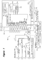
- Figure 1 is a block diagram of an implementation of vehicle diagnostic test system.
- Figure 2 shows an isometric view of a first embodiment of the vehicle diagnostic test system where the integrated control means is electrically coupled to a single instrumentation module.
- FIG 3 is a block diagram of an instrumentation modules included in the system shown in Figure 1.
- Figure 4 shows an isometric view of an alternative embodiment of the vehicle diagnostic test system where the integrated control means is electrically coupled to a first and second instrumentation modules.
- FIG. 5 shows an isometric view of the preferred vehicle diagnostic test system where the docking station is mechanically and electrically coupled to the integrated control means.
- Figure 6 shows a block diagram of an alternative embodiment of vehicle diagnostic test system where a removable CD ROM is included in the integrated control module.
- Figure 1 shows a preferred vehicle diagnostic test system 100 which includes: an integrated control means 102 for providing access to a technical database comprised of stored information records, with migration capacity between related records, and further to provide selective access to particular portions of information within the database, the integrated control means 102 including a user interface 106 responsive to operation by a user to provide commands, and a processing means 108 responsive to commands entered through the user interface 106 to access the information; and at least one instrumentation module 110 electrically coupled to the integrated control means 102, the instrumentation module 110 being responsive to commands entered through the user interface 106.
- the integrated control means 102 is electrically coupled to a docking station 111, the docking station 111 including a docking connector means 112 for electrically coupling the integrated control means 102 to the docking station 111.
- the integrated control means 102 combines or integrates the user interface 106 with a computing means 114, which includes a processing means 108 and an integrated controller memory means 116 in a single, easy to carry structure.
- the processing means is typically a microprocessor such as the Pentium processor manufactured by Intel Corporation.
- the integrated control means 102 provides the user with any or all visual, audible, and/or tactile means by which to communicate to the remainder of the system.
- the user interface 106 shown Figure 1 includes only an LCD panel 120, a touch screen 122, and a mouse 124, other user interfaces may be used.
- the integrated control means 102 provides information to and receives commands from the user to process or communicate to the instrumentation modules 110 via the corresponding instrumentation module bus 126.
- the instrumentation module bus 126 for electrically coupling the vehicle instrumentation module 110 to the integrated control means 102 is an IEEE 1394 bus.
- the IEEE 1394 bus is a bus targeted for consumer products, the IEEE 1394 bus provides high throughput performance, low and predictable latency, true plug and play support and hot plug-in connectivity.
- the IEEE 1394 supports both synchronous and asynchronous data transmission at a throughput of up to 400 MB/sec. This high rate of data throughput is critical in systems having multiple vehicle instrumentation modules which have high speed data channels.
- test diagnostic system 100 facilitates the placement and movement of the vehicle instrumentation modules by the technician during testing. Compared to cables used in previous test diagnostic systems, the cable which supports the IEEE 1394 bus is much thinner, providing easier movement for the technician. Separation of the functionality between the vehicle instrumentation module and the integrated control means by the IEEE 1394 bus allows the vehicle instrumentation module to be placed in close proximity to the component being tested. In addition, the physical separation of the vehicle instrumentation module and the integrated control means by a cable allows the vehicle instrumentation module to be more easily connected to the vehicle battery. Connecting the vehicle instrumentation module directly to the vehicle battery results in a smaller power supply for the integrated control means, a decreased power drain from the J1962 vehicle connector and a smaller, lighter and cooler integrated control means.
- the bus to the removable CD ROM is an IEEE 1394 bus
- the bus for the modem is a RS232 bus
- the bus for the keyboard and printer is a USB bus.
- these buses and the components to which they are connected to may change.
- the IEEE 1394 bus is connected to a CD ROM
- the type of device the IEEE 1394 bus is connected to may change.
- the IEEE 1394 interface on the docking station could be used for other digital devices such as digital cameras, scanners and printers. These devices could be used for reporting of a mechanical defect, parts failure, capturing engine noise, documenting mechanical wear, or adding pictures to customer reports.
- a wider selection of peripheral is available for use in combination with the test diagnostic system 100.
- the test diagnostic system comprises at least one instrumentation module for performing measurements.
- Figure 2 shows an isometric view of a first embodiment of the vehicle diagnostic test system where the integrated control means 102 is electrically coupled to a single instrumentation module 110.
- Figure 3 is a block diagram of an instrumentation module 110, such as may be included in the system shown in Figures 1 and 2.
- the instrumentation module 110 is comprised of a common layer 130 and a customized layer 132.
- the common layer 130 typically includes a bus interface 134, a dedicated microcontroller 136 and a power supply 138.
- the custom layer 130 is customized dependent on the function of the module. Examples of instrumentation modules typically found in automotive diagnostic test systems: include a vehicle communication interface (VCI), a digital volt-ohm meter (DVOM ), and an engine analyzer I/F.
- VCI vehicle communication interface
- DVOM digital volt-ohm meter
- I/F engine analyzer I/F.
- the instrumentation module 110 is connected to the vehicle part or system 140 to be tested and provides a bi-directional data path between the integrated control means 102 and the vehicle part being tested 140.
- the vehicle instrumentation module 110 will have an isolated analog/digital input stage to isolate the vehicle communication interface of the integrated controller memory means 116 from the electrical system of the motor vehicle.
- Each instrumentation module 110 further includes its own power supply 136. As shown in Figure 1, the instrumentation module 110 may additionally be electrically coupled to the battery supply 142 of the motor vehicle under test.
- the vehicle diagnostic test system is designed to be scaleable, allowing the customer to determine how many instrumentation modules (how much functionality) are needed for each system. For example, a customer may start with a base unit which includes an integrated control means 102 and a single instrumentation module 110. At a later date, further instrumentation modules 110 may be purchased.
- the vehicle instrumentation module 110 Separating the vehicle instrumentation module from the integrated control means 102 allows the vehicle instrumentation module 110 to be placed directly in the engine compartment. Placing the vehicle instrumentation module directly in the engine compartment allows enhanced cable management since all cables and transducers will be connected directly to the vehicle instrumentation module 110 without weighing down the integrated control means 102. Furthermore, the cables and transducers have shorter lengths, hence making integrated control means 102 lighter to transport. Further, because the instrumentation modules 110 are separate from the integrated control means 102, the instrumentation modules 110 can be built to allow more ruggedness for the harsh environmental conditions (such as high temperature) in the proximity of the component of the vehicle being tested.
- harsh environmental conditions such as high temperature
- the vehicle instrumentation module 110 when there is a need to use the functionality supported by the vehicle instrumentation module 110, a transport device would most likely be used to carry the cables and transducers. Hence, carrying the vehicle instrumentation channel in the transport device would not hinder the technician's mobility.
- a more common configuration of the cables and transducers connected to the module could be left connected, only requiring connection to the vehicle, and a single quick connection to the integrated control means.
- the quick connect and disconnect of the vehicle instrumentation module from the integrated control means enables the technician to use the integrated control means on a second vehicle while the vehicle instrumentation modules is still connected to the first vehicle.
- the vehicle instrumentation module connected to the first vehicle may continue capturing data without being connected to the integrated control means (similar to a flight recorder). This allows for a quick disconnect of the integrated control means from the vehicle under test to be used on a different vehicle and reconnected back to the first vehicle perhaps with new data captured in the module which is ready to be transferred.
- FIG 4 shows an isometric view of an alternative embodiment of the vehicle diagnostic test system where the integrated control means 102 is electrically coupled to a first 150 and a second 154 instrumentation module.
- the VCL instrumentation module includes a microcontroller that is dedicated to communicating with the vehicle on-board computer.
- the VCL circuit module 154 could be incorporated into the integrated control means 102, in the preferred embodiment shown in Figure 1, the VCL instrumentation module is moved outside the integrated control means.
- the configuration shown in Figure 4 will result in a much thinner longer capable between the integrated control means 102 and the VCL instrumentation module 154 and a very short thicker cable positioned between the VCL instrumentation module 154 and the J1962 connector 172.
- the VCL instrumentation module 154 takes its power from the J1962 connector 172 and passes the power lines to the integrated control means 102. Although the net power consumed in this configuration (shown in Figure 4) is slightly higher, the heat generated by the VCL circuit is removed from the integrated control means.
- the integrated control means includes a plurality of ports 156 for communication with peripherals.
- the ports shown in Figure 1 include a port 156a for a display controller, a PCMCIA port 156b, a sound port 156c, an IR port 156d, an RS-232 port 156e, an RS-485 port 156f, a USB port 156g, a LAN port 156h, an Internal RS-233 port 156j, and an IEEE 1394 port 156k.
- the software environment for the test system 100 is preferably a window-based software interface.
- the user operates the integrated control means 102 through the user interface 106 to control the diagnostic test system 100.
- the instrumentation module 110 is connected to a part or system to be tested.
- the instrumentation module 110 may be connected to the electrical system of the vehicle.
- the integrated control means 110 executes diagnostic application programs and commands the instrumentation module 110 to provide status information and/or measurement data.
- the use interface displays 106 the requested information to the user.
- FIG. 1 shows a docking station 111 which can be electrically coupled to the integrated control means 102.
- FIG 5 shows an isometric view of the vehicle diagnostic test system 100 according to the present invention where the docking station 111 is mechanically and electrically coupled to the integrated control means 102.
- the docking station 111 provides access to other peripherals. For example, say the technician switches to test a vehicle whose test diagnostic data is not stored in the integrated control means 102. This will result in an error message, advising technician that the information required to complete his tests is not available. The additional data required to complete testing may be accessed through the docking station 111.
- the docking station 111 provides the following interfaces: an IEEE interface to the CD ROM 160, a parallel interface to a printer or other peripheral, a modem interface, a LAN interface, and a USB interface.
- transfer of the requested information may be easily achieved by transferring information from a technical database memory storage means 166 to the memory of the integrated control means 102.
- the CD ROM 160 is a storage means for the technical database memory storage means 166.
- the technical database memory storage means 166 To transfer vehicle data from the technical database memory storage means, the technical database memory storage means 166 must first be electrically coupled to the integrated controller memory means 116. A command from the user interface will initiate the data transfer.
- the CD ROM 160 is removable and is physically located in the docking station 111. Making the CD ROM 160 removable, allows for easy system upgrades.
- the CD ROM 160 is physically located in the integrated control means 102.
- FIG 6 shows a block diagram of an alternative embodiment of vehicle diagnostic test system 100 where a removable CD ROM 160 is included in the integrated control module 102. This configuration is not preferred, since it reduces the ruggedness of the vehicle diagnostic test system 100.
- placement of the CD ROM 160 in the integrated control means 102 is advantageous as it provides for access to the CD ROM 160 when the system is not electrically connected to the docking station 111 and thus provides an alternative booting device.
- Power can be supplied to the integrated control means 102 from a rechargeable internal battery power source 168 or from an external power source 170 if the internal power supply develops a low battery condition. Power can be supplied or the internal battery power source 168 can be recharged via the docking station 111.
- the integrated control means 102 further includes a battery charging circuit. This minimizes the wiring in the docking connector, eliminating the battery status sensing wires. The charging circuit will be active only when the integrated control means is connected to the docking station or alternatively when the integrated control means powered from the J1962 and the J1962 is in its sleep mode. When connected to the docking station 111, only DC power is supplied to the integrated control means 102.
- modular wireless diagnostic, test and information system is susceptible to being used in various applications, it has been found to be particularly advantageous for use in the maintenance and repair of motor vehicles. Therefore, an embodiment of the modular diagnostic, test and information system will be described in connection with service of a motor vehicle. However, it is to be understood that the invention is not limited to motor vehicle maintenance and repair and may also be applicable to non-motor vehicle applications.
Abstract
Description
Claims (10)
- A diagnostic system for providing information to maintain and repair equipment or provide services, comprising:integrated control means (102) for providing access to a technical database including stored information records with migration capacity between related records, and for providing selective access to particular portions of information within the database, the integrated control means including a user interface (106) responsive to operation by a user to provide commands, and processing means (108) responsive to commands entered through the user interface to access the information; andat least one instrumentation module (110) electrically coupled to the integrated control means, the instrumentation module being responsive to commands entered through the user interface.
- A diagnostic system as in claim 1, wherein the means for electrically coupling the integrated control means to the at least one instrumentation module is a IEEE 1394 bus.
- A diagnostic system as in claim 1 or 2, wherein the integrated control means (102) includes an integrated controller memory means (116), wherein the technical database is transferable to the integrated controller memory means from a technical database memory storage means, the data transfer occurring during a time period when the technical database storage means is electrically coupled to the integrated controller memory means.
- A diagnostic system as in claim 3, wherein the technical database memory storage means is removable.
- A diagnostic system as in claim 3 or 4, wherein the technical database memory storage means is a CD ROM.
- A diagnostic system as in any preceding claim, wherein the integrated control means includes an integrated controller memory means and further wherein an applications program for controlling the vehicle test diagnostic system is stored in the integrated controller memory means.
- A diagnostic system as in any preceding claim, comprising a docking station means electrically coupled to the integrated control means.
- A diagnostic system as in claim 7, wherein the docking station means includes technical database memory storage means and/or means for communicating with a means for storing test vehicle data and/or power supply means.
- A diagnostic system as in any preceding claim, wherein the at least one vehicle instrumentation module is electrically coupled to a battery of a vehicle currently under test.
- A diagnostic system as in any preceding claim, wherein the at least one vehicle instrumentation module includes a vehicle instrumentation power supply.
Applications Claiming Priority (2)
| Application Number | Priority Date | Filing Date | Title |
|---|---|---|---|
| US720390 | 1996-09-30 | ||
| US08/720,390 US5916287A (en) | 1996-09-30 | 1996-09-30 | Modular automotive diagnostic, test and information system |
Publications (2)
| Publication Number | Publication Date |
|---|---|
| EP0833140A2 true EP0833140A2 (en) | 1998-04-01 |
| EP0833140A3 EP0833140A3 (en) | 1999-01-27 |
Family
ID=24893839
Family Applications (1)
| Application Number | Title | Priority Date | Filing Date |
|---|---|---|---|
| EP97307076A Withdrawn EP0833140A3 (en) | 1996-09-30 | 1997-09-12 | Diagnostic system |
Country Status (3)
| Country | Link |
|---|---|
| US (1) | US5916287A (en) |
| EP (1) | EP0833140A3 (en) |
| JP (1) | JPH10109623A (en) |
Cited By (10)
| Publication number | Priority date | Publication date | Assignee | Title |
|---|---|---|---|---|
| WO1999054698A2 (en) * | 1998-04-17 | 1999-10-28 | Siemens Aktiengesellschaft | System and method for configuring and conducting test processes |
| WO2000007013A3 (en) * | 1998-07-31 | 2000-09-28 | Abbott Lab | Analyte test instrument system including data management system |
| EP1195593A1 (en) * | 2000-10-05 | 2002-04-10 | Techspace Aero S.A. | Test installation for testing aircraft engines |
| EP1236120A1 (en) * | 1999-12-07 | 2002-09-04 | Pei ELectronics Inc. | Measurement module and system for monitoring the status of armored vehicle electronic components |
| EP1215086A3 (en) * | 2000-12-13 | 2002-10-16 | Denso Corporation | Controller for vehicle with information providing function and recording medium |
| EP1281948A1 (en) * | 2001-08-03 | 2003-02-05 | Drecq Daniel Technologies D 2 T | Computerprogram for controlling and commanding a test bench |
| EP1376094A2 (en) * | 2002-06-22 | 2004-01-02 | Robert Bosch Gmbh | Method and device for diagnosing components of a vehicle |
| DE102004044881A1 (en) * | 2004-09-14 | 2005-11-17 | Siemens Ag | Vehicle diagnosis interface has housing with computer communications unit and exchangeable multiplexer provided with multipin connector |
| CN104913804A (en) * | 2015-06-26 | 2015-09-16 | 武汉光庭科技有限公司 | Product detection method and information analysis and excitation generation box |
| CN113969844A (en) * | 2020-07-22 | 2022-01-25 | 广州汽车集团股份有限公司 | CAN bus and engine control unit communication data processing method and system |
Families Citing this family (108)
| Publication number | Priority date | Publication date | Assignee | Title |
|---|---|---|---|---|
| US9443358B2 (en) * | 1995-06-07 | 2016-09-13 | Automotive Vehicular Sciences LLC | Vehicle software upgrade techniques |
| US8019501B2 (en) * | 1995-06-07 | 2011-09-13 | Automotive Technologies International, Inc. | Vehicle diagnostic and prognostic methods and systems |
| US8140358B1 (en) | 1996-01-29 | 2012-03-20 | Progressive Casualty Insurance Company | Vehicle monitoring system |
| US8090598B2 (en) * | 1996-01-29 | 2012-01-03 | Progressive Casualty Insurance Company | Monitoring system for determining and communicating a cost of insurance |
| US6115137A (en) | 1996-12-06 | 2000-09-05 | Canon Kabushiki Kaisha | Image processing system, digital camera, and printing apparatus |
| JPH10170311A (en) * | 1996-12-12 | 1998-06-26 | Nippon Seiki Co Ltd | Instrument device for vehicle |
| JPH10228365A (en) * | 1997-02-14 | 1998-08-25 | Canon Inc | Printer, print system, and printing method |
| US6356968B1 (en) * | 1997-09-03 | 2002-03-12 | Cirrus Logic, Inc | Apparatus and method for transparent USB-to-1394 bridging and video delivery between a host computer system and a remote peripheral device |
| US6064721A (en) | 1997-10-22 | 2000-05-16 | Telecommunications Techniques Corporation | Modular test instrument |
| US8958998B2 (en) * | 1997-11-03 | 2015-02-17 | Midtronics, Inc. | Electronic battery tester with network communication |
| US6314422B1 (en) * | 1997-12-09 | 2001-11-06 | Chrysler Corporation | Method for softlinking between documents in a vehicle diagnostic system |
| US6282469B1 (en) * | 1998-07-22 | 2001-08-28 | Snap-On Technologies, Inc. | Computerized automotive service equipment using multipoint serial link data transmission protocols |
| US6311162B1 (en) * | 1998-07-25 | 2001-10-30 | Ernst F. Reichwein | Interactive symptomatic recording system and methods |
| US6097998A (en) * | 1998-09-11 | 2000-08-01 | Alliedsignal Truck Brake Systems Co. | Method and apparatus for graphically monitoring and controlling a vehicle anti-lock braking system |
| US6189057B1 (en) * | 1998-09-14 | 2001-02-13 | Chrysler Corporation | Motor vehicle accessory interface for transferring serial data with and supplying DC power to external accessory device |
| US10240935B2 (en) | 1998-10-22 | 2019-03-26 | American Vehicular Sciences Llc | Vehicle software upgrade techniques |
| US6891803B1 (en) | 1998-12-18 | 2005-05-10 | Sunrise Telecom, Inc. | Telecommunications transmission test set |
| GB2351884B (en) * | 1999-04-10 | 2002-07-31 | Peter Strong | Data transmission method |
| USD421962S (en) * | 1999-04-21 | 2000-03-28 | Acco Brands, Inc. | USB hub |
| DE19928681A1 (en) * | 1999-06-23 | 2000-12-28 | Wuerth Adolf Gmbh & Co Kg | Arrangement for measuring and evaluating maintenance values |
| US6567876B1 (en) * | 1999-12-03 | 2003-05-20 | Hewlett-Packard Development Company, L.P. | Docking PCI to PCI bridge using IEEE 1394 link |
| US6236917B1 (en) * | 1999-12-21 | 2001-05-22 | Spx Corporation | Open architecture diagnostic tool |
| US6526340B1 (en) * | 1999-12-21 | 2003-02-25 | Spx Corporation | Multi-vehicle communication interface |
| US7446536B2 (en) | 2000-03-27 | 2008-11-04 | Midtronics, Inc. | Scan tool for electronic battery tester |
| US6629029B1 (en) * | 2000-03-28 | 2003-09-30 | Jacqueline A Giles | Multi-purpose plug-in monitor for vehicles |
| AU2001259611A1 (en) * | 2000-05-08 | 2001-11-20 | Pradeep R Triphathi | Monitoring of vehicle health based on historical information |
| DE10049743A1 (en) * | 2000-09-29 | 2002-04-11 | Wtw Weilheim | Modular measuring system for a water treatment plant, comprises a housing with sensors, shared contacts and a unique identification unit |
| EP1229450A1 (en) | 2001-01-31 | 2002-08-07 | Sony International (Europe) GmbH | Diagnostic method and system |
| US6892216B2 (en) | 2001-02-13 | 2005-05-10 | Snap-On Incorporated | Common platform for use in automotive services |
| US6732028B2 (en) * | 2001-02-15 | 2004-05-04 | Joe Auto, Inc. | Network based automotive service monitoring system |
| US20020111844A1 (en) * | 2001-02-15 | 2002-08-15 | Randy Vanstory | Network based automotive service event scheduling and monitoring system |
| US6625504B2 (en) | 2001-03-22 | 2003-09-23 | Honeywell International Inc. | Auxiliary power unit engine monitoring system |
| DE10119270A1 (en) * | 2001-04-20 | 2002-10-24 | Zahnradfabrik Friedrichshafen | Measurement arrangement for motor vehicle data has measurement sensors and electronics for recording and processing measurement data and characteristic values for the vehicle and a control box that automates the whole process |
| US6617857B1 (en) | 2001-06-29 | 2003-09-09 | Spx Corporation | DIS ignition signal processing for automotive engine analyzer |
| US20030130774A1 (en) | 2002-01-03 | 2003-07-10 | Tripathi Pradeep R. | Vehicle inspection enforcement system and method offering multiple data transmissions on the road |
| US7778750B2 (en) * | 2002-02-25 | 2010-08-17 | Cummins Inc. | Vehicle communications network adapter |
| US20030167345A1 (en) * | 2002-02-25 | 2003-09-04 | Knight Alexander N. | Communications bridge between a vehicle information network and a remote system |
| US7337255B2 (en) * | 2002-06-12 | 2008-02-26 | The Boeing Company | Distributed data handling and processing resources system |
| US10817937B1 (en) | 2003-02-28 | 2020-10-27 | Trading Technologies International, Inc. | Method and system for internal matching |
| US7516244B2 (en) * | 2003-07-02 | 2009-04-07 | Caterpillar Inc. | Systems and methods for providing server operations in a work machine |
| US7532640B2 (en) | 2003-07-02 | 2009-05-12 | Caterpillar Inc. | Systems and methods for performing protocol conversions in a machine |
| US7983820B2 (en) | 2003-07-02 | 2011-07-19 | Caterpillar Inc. | Systems and methods for providing proxy control functions in a work machine |
| US9018958B2 (en) * | 2003-09-05 | 2015-04-28 | Midtronics, Inc. | Method and apparatus for measuring a parameter of a vehicle electrical system |
| US9255955B2 (en) | 2003-09-05 | 2016-02-09 | Midtronics, Inc. | Method and apparatus for measuring a parameter of a vehicle electrical system |
| US7584029B2 (en) * | 2003-12-31 | 2009-09-01 | Teradyne, Inc. | Telematics-based vehicle data acquisition architecture |
| US20050257038A1 (en) * | 2004-05-11 | 2005-11-17 | Jason Miller | Automotive electronic control unit and a method for storing configuration data in the same |
| US7222053B2 (en) | 2004-07-12 | 2007-05-22 | Mack Trucks, Inc. | Event-driven portable data bus message logger |
| US20060036355A1 (en) * | 2004-08-10 | 2006-02-16 | Schaar David L | Connector with back-up power via data link connector |
| US7805228B2 (en) * | 2004-08-19 | 2010-09-28 | Spx Corporation | Vehicle diagnostic device |
| US8344685B2 (en) | 2004-08-20 | 2013-01-01 | Midtronics, Inc. | System for automatically gathering battery information |
| US9496720B2 (en) | 2004-08-20 | 2016-11-15 | Midtronics, Inc. | System for automatically gathering battery information |
| US7248954B2 (en) * | 2005-03-23 | 2007-07-24 | Spx Corporation | Integrated circuit vehicle diagnostics interface adapter apparatus and method |
| US20060229777A1 (en) * | 2005-04-12 | 2006-10-12 | Hudson Michael D | System and methods of performing real-time on-board automotive telemetry analysis and reporting |
| US7990155B2 (en) | 2005-04-28 | 2011-08-02 | Auto Meter Products, Inc. | Heavy duty battery system tester and method |
| US20060244423A1 (en) * | 2005-04-28 | 2006-11-02 | Auto Meter Products, Inc. | Heavy duty battery system testor and method |
| US7596435B1 (en) | 2005-08-03 | 2009-09-29 | Systech International, Llc | Vehicle communication system and method with mobile data collection |
| JP2007055508A (en) | 2005-08-25 | 2007-03-08 | Sony Corp | On-vehicle equipment |
| US7596636B2 (en) * | 2005-09-23 | 2009-09-29 | Joseph Gormley | Systems and methods for implementing a vehicle control and interconnection system |
| US7590768B2 (en) * | 2005-09-23 | 2009-09-15 | Joseph Gormley | Control and interconnection system |
| US7571035B2 (en) * | 2006-03-31 | 2009-08-04 | Spx Corporation | Simultaneous vehicle protocol communication apparatus and method |
| US20080071440A1 (en) * | 2006-09-15 | 2008-03-20 | Kam Patel | Method and System of Power Management for a Vehicle Communication Interface |
| US20080133308A1 (en) * | 2006-11-27 | 2008-06-05 | Harris James E | Leakage location methods |
| US8694328B1 (en) | 2006-12-14 | 2014-04-08 | Joseph Gormley | Vehicle customization and personalization activities |
| US7751956B2 (en) * | 2006-12-29 | 2010-07-06 | Detroit Diesel Corporation | Distributed automotive diagnostic system with a single diagnostic protocol server and multiple data source modules for internal combustion engines |
| BRPI0700713A (en) * | 2007-02-01 | 2008-09-16 | Marcelo Campi Lima | automotive vehicle maintenance control system and computer |
| DE102007032627A1 (en) * | 2007-07-11 | 2009-01-15 | Vector Informatik Gmbh | test device |
| DE112008001881B4 (en) | 2007-07-17 | 2024-04-11 | Midtronics, Inc. | Battery tester for electric vehicles |
| US9274157B2 (en) | 2007-07-17 | 2016-03-01 | Midtronics, Inc. | Battery tester for electric vehicle |
| TW200922821A (en) * | 2007-11-29 | 2009-06-01 | Kwang Yang Motor Co | Handheld diagnostic device for vehicle |
| US8340855B2 (en) | 2008-04-22 | 2012-12-25 | Spx Corporation | USB isolation for vehicle communication interface |
| US7936261B2 (en) * | 2008-09-26 | 2011-05-03 | Caterpillar Inc. | System and method for testing a machine using an interactive test script |
| US8977526B1 (en) * | 2009-02-06 | 2015-03-10 | Exelon Generation Company, Llc | Nuclear power plant control room simulator |
| US8184437B2 (en) * | 2009-02-17 | 2012-05-22 | Pallas Systems, Llc | Modular test systems for severe environments |
| US20100217479A1 (en) * | 2009-02-23 | 2010-08-26 | Bae Systems Information And Electronic Systems Integration, Inc. | Diagnostic connector assembly (DCA) interface unit (DIU) |
| EP2221790B1 (en) * | 2009-02-24 | 2020-11-18 | Panasonic Intellectual Property Management Co., Ltd. | Wireless communications system for tool |
| US9916625B2 (en) | 2012-02-02 | 2018-03-13 | Progressive Casualty Insurance Company | Mobile insurance platform system |
| US9588185B2 (en) | 2010-02-25 | 2017-03-07 | Keith S. Champlin | Method and apparatus for detecting cell deterioration in an electrochemical cell or battery |
| CN102804478B (en) | 2010-03-03 | 2015-12-16 | 密特电子公司 | For the watch-dog of front terminals battery |
| US9229062B2 (en) | 2010-05-27 | 2016-01-05 | Midtronics, Inc. | Electronic storage battery diagnostic system |
| KR20130030766A (en) | 2010-06-03 | 2013-03-27 | 미드트로닉스, 인크. | Battery pack maintenance for electric vehicles |
| US10046649B2 (en) | 2012-06-28 | 2018-08-14 | Midtronics, Inc. | Hybrid and electric vehicle battery pack maintenance device |
| US11740294B2 (en) | 2010-06-03 | 2023-08-29 | Midtronics, Inc. | High use battery pack maintenance |
| US9419311B2 (en) | 2010-06-18 | 2016-08-16 | Midtronics, Inc. | Battery maintenance device with thermal buffer |
| US8747148B2 (en) | 2010-08-03 | 2014-06-10 | Bosch Automotive Service Solutions Llc | Diagnostic tool with recessed connector |
| US9201120B2 (en) | 2010-08-12 | 2015-12-01 | Midtronics, Inc. | Electronic battery tester for testing storage battery |
| WO2013070850A2 (en) | 2011-11-10 | 2013-05-16 | Midtronics, Inc. | Battery pack tester |
| EP2820303A1 (en) | 2012-02-03 | 2015-01-07 | Carter Fuel Systems, LLC | Electrical diagnostic tool |
| US9851411B2 (en) | 2012-06-28 | 2017-12-26 | Keith S. Champlin | Suppressing HF cable oscillations during dynamic measurements of cells and batteries |
| US11325479B2 (en) | 2012-06-28 | 2022-05-10 | Midtronics, Inc. | Hybrid and electric vehicle battery maintenance device |
| US9208525B2 (en) | 2013-03-10 | 2015-12-08 | State Farm Mutual Automobile Insurance Company | System and method for determining and monitoring auto insurance incentives |
| US9244100B2 (en) | 2013-03-15 | 2016-01-26 | Midtronics, Inc. | Current clamp with jaw closure detection |
| US10698577B2 (en) * | 2013-03-18 | 2020-06-30 | Dennis Bushmitch | Integrated mobile device |
| US9312575B2 (en) | 2013-05-16 | 2016-04-12 | Midtronics, Inc. | Battery testing system and method |
| CN103353754B (en) * | 2013-06-28 | 2016-05-25 | 惠州市德赛西威汽车电子股份有限公司 | A kind of production method of automobile instrument |
| US10843574B2 (en) | 2013-12-12 | 2020-11-24 | Midtronics, Inc. | Calibration and programming of in-vehicle battery sensors |
| EP2897229A1 (en) | 2014-01-16 | 2015-07-22 | Midtronics, Inc. | Battery clamp with endoskeleton design |
| US10473555B2 (en) | 2014-07-14 | 2019-11-12 | Midtronics, Inc. | Automotive maintenance system |
| US10222397B2 (en) | 2014-09-26 | 2019-03-05 | Midtronics, Inc. | Cable connector for electronic battery tester |
| WO2016123075A1 (en) | 2015-01-26 | 2016-08-04 | Midtronics, Inc. | Alternator tester |
| US9966676B2 (en) | 2015-09-28 | 2018-05-08 | Midtronics, Inc. | Kelvin connector adapter for storage battery |
| US10608353B2 (en) | 2016-06-28 | 2020-03-31 | Midtronics, Inc. | Battery clamp |
| US11054480B2 (en) | 2016-10-25 | 2021-07-06 | Midtronics, Inc. | Electrical load for electronic battery tester and electronic battery tester including such electrical load |
| US11513160B2 (en) | 2018-11-29 | 2022-11-29 | Midtronics, Inc. | Vehicle battery maintenance device |
| US11566972B2 (en) | 2019-07-31 | 2023-01-31 | Midtronics, Inc. | Tire tread gauge using visual indicator |
| US11545839B2 (en) | 2019-11-05 | 2023-01-03 | Midtronics, Inc. | System for charging a series of connected batteries |
| US11668779B2 (en) | 2019-11-11 | 2023-06-06 | Midtronics, Inc. | Hybrid and electric vehicle battery pack maintenance device |
| US11474153B2 (en) | 2019-11-12 | 2022-10-18 | Midtronics, Inc. | Battery pack maintenance system |
| US11486930B2 (en) | 2020-01-23 | 2022-11-01 | Midtronics, Inc. | Electronic battery tester with battery clamp storage holsters |
Citations (3)
| Publication number | Priority date | Publication date | Assignee | Title |
|---|---|---|---|---|
| US5318449A (en) * | 1989-06-07 | 1994-06-07 | Electra International Pty. Ltd. | Method and apparatus for computer-aided diagnosis of engines |
| US5347425A (en) * | 1992-10-15 | 1994-09-13 | Apple Computer, Inc. | Docking station for a portable computer |
| GB2290631A (en) * | 1994-06-24 | 1996-01-03 | Fuji Heavy Ind Ltd | Diagnosis system for motor vehicle |
Family Cites Families (9)
| Publication number | Priority date | Publication date | Assignee | Title |
|---|---|---|---|---|
| US4113980A (en) * | 1974-12-19 | 1978-09-12 | United Technologies Corporation | Vehicle diagnostic hand control |
| US4694408A (en) * | 1986-01-15 | 1987-09-15 | Zaleski James V | Apparatus for testing auto electronics systems |
| GB2210999B (en) * | 1987-10-09 | 1992-04-29 | Fuji Heavy Ind Ltd | Diagnostic system for a motor vehicle |
| JPH0830672B2 (en) * | 1987-12-11 | 1996-03-27 | 富士重工業株式会社 | Vehicle diagnostic device |
| US5526493A (en) * | 1993-06-03 | 1996-06-11 | Dell Usa | Docking detection and suspend circuit for portable computer/expansion chassis docking system |
| US5541840A (en) * | 1993-06-25 | 1996-07-30 | Chrysler Corporation | Hand held automotive diagnostic service tool |
| US5555498A (en) * | 1994-03-18 | 1996-09-10 | Chrysler Corporation | Circuit and method for interfacing vehicle controller and diagnostic test instrument |
| US5717595A (en) * | 1995-01-12 | 1998-02-10 | Cherrington; John K. | Integrated automated vehicle analysis |
| US5675139A (en) * | 1995-05-18 | 1997-10-07 | Symbol Technologies, Inc. | Interface arrangement for use with consumer devices |
-
1996
- 1996-09-30 US US08/720,390 patent/US5916287A/en not_active Expired - Fee Related
-
1997
- 1997-09-02 JP JP9236818A patent/JPH10109623A/en active Pending
- 1997-09-12 EP EP97307076A patent/EP0833140A3/en not_active Withdrawn
Patent Citations (3)
| Publication number | Priority date | Publication date | Assignee | Title |
|---|---|---|---|---|
| US5318449A (en) * | 1989-06-07 | 1994-06-07 | Electra International Pty. Ltd. | Method and apparatus for computer-aided diagnosis of engines |
| US5347425A (en) * | 1992-10-15 | 1994-09-13 | Apple Computer, Inc. | Docking station for a portable computer |
| GB2290631A (en) * | 1994-06-24 | 1996-01-03 | Fuji Heavy Ind Ltd | Diagnosis system for motor vehicle |
Non-Patent Citations (1)
| Title |
|---|
| BLOKS R H J: "The IEEE-1394 high speed serial bus" PHILIPS JOURNAL OF RESEARCH, vol. 50, no. 1, 1996, page 209-216 XP004008212 * |
Cited By (21)
| Publication number | Priority date | Publication date | Assignee | Title |
|---|---|---|---|---|
| WO1999054698A2 (en) * | 1998-04-17 | 1999-10-28 | Siemens Aktiengesellschaft | System and method for configuring and conducting test processes |
| WO1999054698A3 (en) * | 1998-04-17 | 2000-03-02 | Siemens Ag | System and method for configuring and conducting test processes |
| WO2000007013A3 (en) * | 1998-07-31 | 2000-09-28 | Abbott Lab | Analyte test instrument system including data management system |
| US7077328B2 (en) | 1998-07-31 | 2006-07-18 | Abbott Laboratories | Analyte test instrument system including data management system |
| EP1236120A4 (en) * | 1999-12-07 | 2004-06-16 | Pei Electronics Inc | Measurement module and system for monitoring the status of armored vehicle electronic components |
| EP1241578A3 (en) * | 1999-12-07 | 2004-03-17 | Pei ELectronics Inc. | Measurement module and system for monitoring the status of armored vehicles electronic components |
| EP1246067A2 (en) * | 1999-12-07 | 2002-10-02 | Pei ELectronics Inc. | Measurement module and system for monitoring the status of armored vehicles electronic components |
| EP1236120A1 (en) * | 1999-12-07 | 2002-09-04 | Pei ELectronics Inc. | Measurement module and system for monitoring the status of armored vehicle electronic components |
| EP1241578A2 (en) * | 1999-12-07 | 2002-09-18 | Pei ELectronics Inc. | Measurement module and system for monitoring the status of armored vehicles electronic components |
| EP1246067A3 (en) * | 1999-12-07 | 2004-03-17 | Pei ELectronics Inc. | Measurement module and system for monitoring the status of armored vehicles electronic components |
| EP1195593A1 (en) * | 2000-10-05 | 2002-04-10 | Techspace Aero S.A. | Test installation for testing aircraft engines |
| US6738696B2 (en) | 2000-12-13 | 2004-05-18 | Denso Corporation | Controller for vehicle with information providing function and recording medium |
| EP1215086A3 (en) * | 2000-12-13 | 2002-10-16 | Denso Corporation | Controller for vehicle with information providing function and recording medium |
| WO2003014692A1 (en) * | 2001-08-03 | 2003-02-20 | Drecq Daniel Technologies D 2 T | Computer programme for monitoring and controlling a test stand |
| EP1281948A1 (en) * | 2001-08-03 | 2003-02-05 | Drecq Daniel Technologies D 2 T | Computerprogram for controlling and commanding a test bench |
| EP1376094A2 (en) * | 2002-06-22 | 2004-01-02 | Robert Bosch Gmbh | Method and device for diagnosing components of a vehicle |
| EP1376094A3 (en) * | 2002-06-22 | 2004-06-09 | Robert Bosch Gmbh | Method and device for diagnosing components of a vehicle |
| DE102004044881A1 (en) * | 2004-09-14 | 2005-11-17 | Siemens Ag | Vehicle diagnosis interface has housing with computer communications unit and exchangeable multiplexer provided with multipin connector |
| CN104913804A (en) * | 2015-06-26 | 2015-09-16 | 武汉光庭科技有限公司 | Product detection method and information analysis and excitation generation box |
| CN113969844A (en) * | 2020-07-22 | 2022-01-25 | 广州汽车集团股份有限公司 | CAN bus and engine control unit communication data processing method and system |
| CN113969844B (en) * | 2020-07-22 | 2023-09-12 | 广州汽车集团股份有限公司 | Communication data processing method and system for CAN bus and engine control unit |
Also Published As
| Publication number | Publication date |
|---|---|
| US5916287A (en) | 1999-06-29 |
| EP0833140A3 (en) | 1999-01-27 |
| JPH10109623A (en) | 1998-04-28 |
Similar Documents
| Publication | Publication Date | Title |
|---|---|---|
| US5916287A (en) | Modular automotive diagnostic, test and information system | |
| US6094609A (en) | Modular wireless diagnostic, test, and information | |
| US5850209A (en) | Computer system having remotely operated interactive display | |
| US7212911B2 (en) | Alternator and starter tester apparatus and method | |
| US6874680B1 (en) | Remote updating method and apparatus | |
| US5758300A (en) | Diagnosis system for motor vehicles and the method thereof | |
| US5432705A (en) | Administrative computer and testing apparatus | |
| US8226008B2 (en) | Alternator and starter tester with bar code functionality and method | |
| AU723177B2 (en) | Portable, self-contained data collection systems and methods | |
| USRE39619E1 (en) | Automotive code reader | |
| US8442514B2 (en) | System and method for facilitating diagnosis and maintenance of a mobile conveyance | |
| EP2859454B1 (en) | Modular docking station for enclosing mobile devices | |
| US20040064226A1 (en) | Multi-application data display | |
| US20060041349A1 (en) | Vehicle diagnostic device | |
| US20100256864A1 (en) | System and method for facilitating diagnosis and maintenance of a mobile conveyance | |
| WO2000034838A1 (en) | Modular vehicle diagnostic system | |
| EP1492012B1 (en) | System for collecting operation data of work machine | |
| WO2010019771A1 (en) | Docked/undocked vehicle communication interface module | |
| EP1319556B1 (en) | Control system and method for battery control unit | |
| CN110940532A (en) | Vehicle energy flow testing system and method | |
| US5691926A (en) | Integrated test tools for portable computer | |
| WO1989006839A1 (en) | Interchangeable diagnostic instrument system | |
| JP3345827B2 (en) | Vehicle diagnostic device | |
| CN116184096A (en) | Multifunctional unmanned aerial vehicle data monitoring recorder | |
| CA2357240C (en) | Remote updating method and apparatus |
Legal Events
| Date | Code | Title | Description |
|---|---|---|---|
| PUAI | Public reference made under article 153(3) epc to a published international application that has entered the european phase |
Free format text: ORIGINAL CODE: 0009012 |
|
| AK | Designated contracting states |
Kind code of ref document: A2 Designated state(s): DE FR GB |
|
| PUAL | Search report despatched |
Free format text: ORIGINAL CODE: 0009013 |
|
| AK | Designated contracting states |
Kind code of ref document: A3 Designated state(s): AT BE CH DE DK ES FI FR GB GR IE IT LI LU MC NL PT SE |
|
| 17P | Request for examination filed |
Effective date: 19990419 |
|
| AKX | Designation fees paid |
Free format text: DE FR GB |
|
| RAP1 | Party data changed (applicant data changed or rights of an application transferred) |
Owner name: HEWLETT-PACKARD COMPANY, A DELAWARE CORPORATION |
|
| RAP1 | Party data changed (applicant data changed or rights of an application transferred) |
Owner name: AGILENT TECHNOLOGIES, INC. |
|
| RAP1 | Party data changed (applicant data changed or rights of an application transferred) |
Owner name: AGILENT TECHNOLOGIES INC. |
|
| RAP1 | Party data changed (applicant data changed or rights of an application transferred) |
Owner name: AGILENT TECHNOLOGIES INC. A DELAWARE CORPORATION |
|
| RAP1 | Party data changed (applicant data changed or rights of an application transferred) |
Owner name: AGILENT TECHNOLOGIES, INC. (A DELAWARE CORPORATION |
|
| 17Q | First examination report despatched |
Effective date: 20011001 |
|
| STAA | Information on the status of an ep patent application or granted ep patent |
Free format text: STATUS: THE APPLICATION IS DEEMED TO BE WITHDRAWN |
|
| 18D | Application deemed to be withdrawn |
Effective date: 20040401 |