EP0833280A2 - Modular mailing system - Google Patents

Modular mailing system Download PDF

Info

Publication number
EP0833280A2
EP0833280A2 EP97116466A EP97116466A EP0833280A2 EP 0833280 A2 EP0833280 A2 EP 0833280A2 EP 97116466 A EP97116466 A EP 97116466A EP 97116466 A EP97116466 A EP 97116466A EP 0833280 A2 EP0833280 A2 EP 0833280A2
Authority
EP
European Patent Office
Prior art keywords
printing mechanism
plug
printing
mailing
meter vault
Prior art date
Legal status (The legal status is an assumption and is not a legal conclusion. Google has not performed a legal analysis and makes no representation as to the accuracy of the status listed.)
Withdrawn
Application number
EP97116466A
Other languages
German (de)
French (fr)
Other versions
EP0833280A3 (en
Inventor
Edward P. Cornell
Jerome E. Jackson
Wallace Kirschner
Richard A. Malin
Edward J. Naclerio
Maria P. Parkos
John H. Steinmetz
Current Assignee (The listed assignees may be inaccurate. Google has not performed a legal analysis and makes no representation or warranty as to the accuracy of the list.)
Pitney Bowes Inc
Original Assignee
Pitney Bowes Inc
Priority date (The priority date is an assumption and is not a legal conclusion. Google has not performed a legal analysis and makes no representation as to the accuracy of the date listed.)
Filing date
Publication date
Application filed by Pitney Bowes Inc filed Critical Pitney Bowes Inc
Publication of EP0833280A2 publication Critical patent/EP0833280A2/en
Publication of EP0833280A3 publication Critical patent/EP0833280A3/en
Withdrawn legal-status Critical Current

Links

Images

Classifications

    • GPHYSICS
    • G07CHECKING-DEVICES
    • G07BTICKET-ISSUING APPARATUS; FARE-REGISTERING APPARATUS; FRANKING APPARATUS
    • G07B17/00Franking apparatus
    • G07B17/00733Cryptography or similar special procedures in a franking system
    • GPHYSICS
    • G07CHECKING-DEVICES
    • G07BTICKET-ISSUING APPARATUS; FARE-REGISTERING APPARATUS; FRANKING APPARATUS
    • G07B17/00Franking apparatus
    • G07B17/00185Details internally of apparatus in a franking system, e.g. franking machine at customer or apparatus at post office
    • G07B17/00193Constructional details of apparatus in a franking system
    • GPHYSICS
    • G07CHECKING-DEVICES
    • G07BTICKET-ISSUING APPARATUS; FARE-REGISTERING APPARATUS; FRANKING APPARATUS
    • G07B17/00Franking apparatus
    • G07B17/00459Details relating to mailpieces in a franking system
    • G07B17/00508Printing or attaching on mailpieces
    • GPHYSICS
    • G07CHECKING-DEVICES
    • G07BTICKET-ISSUING APPARATUS; FARE-REGISTERING APPARATUS; FRANKING APPARATUS
    • G07B17/00Franking apparatus
    • G07B17/00185Details internally of apparatus in a franking system, e.g. franking machine at customer or apparatus at post office
    • G07B17/00193Constructional details of apparatus in a franking system
    • G07B2017/00225Vending machine or POS (Point Of Sale) apparatus
    • GPHYSICS
    • G07CHECKING-DEVICES
    • G07BTICKET-ISSUING APPARATUS; FARE-REGISTERING APPARATUS; FRANKING APPARATUS
    • G07B17/00Franking apparatus
    • G07B17/00185Details internally of apparatus in a franking system, e.g. franking machine at customer or apparatus at post office
    • G07B17/00193Constructional details of apparatus in a franking system
    • G07B2017/00233Housing, e.g. lock or hardened casing
    • GPHYSICS
    • G07CHECKING-DEVICES
    • G07BTICKET-ISSUING APPARATUS; FARE-REGISTERING APPARATUS; FRANKING APPARATUS
    • G07B17/00Franking apparatus
    • G07B17/00185Details internally of apparatus in a franking system, e.g. franking machine at customer or apparatus at post office
    • G07B17/00193Constructional details of apparatus in a franking system
    • G07B2017/00241Modular design
    • GPHYSICS
    • G07CHECKING-DEVICES
    • G07BTICKET-ISSUING APPARATUS; FARE-REGISTERING APPARATUS; FRANKING APPARATUS
    • G07B17/00Franking apparatus
    • G07B17/00459Details relating to mailpieces in a franking system
    • G07B17/00508Printing or attaching on mailpieces
    • G07B2017/00516Details of printing apparatus
    • G07B2017/00524Printheads
    • G07B2017/00532Inkjet
    • GPHYSICS
    • G07CHECKING-DEVICES
    • G07BTICKET-ISSUING APPARATUS; FARE-REGISTERING APPARATUS; FRANKING APPARATUS
    • G07B17/00Franking apparatus
    • G07B17/00733Cryptography or similar special procedures in a franking system
    • G07B2017/00741Cryptography or similar special procedures in a franking system using specific cryptographic algorithms or functions
    • G07B2017/0075Symmetric, secret-key algorithms, e.g. DES, RC2, RC4, IDEA, Skipjack, CAST, AES
    • GPHYSICS
    • G07CHECKING-DEVICES
    • G07BTICKET-ISSUING APPARATUS; FARE-REGISTERING APPARATUS; FRANKING APPARATUS
    • G07B17/00Franking apparatus
    • G07B17/00733Cryptography or similar special procedures in a franking system
    • G07B2017/00959Cryptographic modules, e.g. a PC encryption board
    • G07B2017/00967PSD [Postal Security Device] as defined by the USPS [US Postal Service]

Definitions

  • This invention relates to mailing apparatus and mailing systems.
  • the invention is applicable to a digital mailing system incorporating a modular design.
  • Value dispensing systems are devices which dispense an indication of value. Examples of such value dispensing systems are postage meters, tax stamp machines, lottery vending machines, and admission ticket dispensing machines.
  • postage meters the indication of value printed, on a mailpiece or mailing label, is a postal indicia.
  • the postage meter can be a stand-alone type postage meter containing, within a single securely sealed housing, accounting structure to account for the value of the postage dispensed by the meter and the total amount of postage funds added to the meter.
  • the accounting structure is mechanically coupled to the printing mechanism which prints the postal indicia.
  • both the accounting structure and the printing mechanism are contained in the securely sealed housing except for that portion of the printing mechanism which necessarily extends out of the housing to print the postal indicia.
  • the sealed secure housing has conventional mechanical security devices, such as sealed screws, which permit a visual indication that tampering of the postage meter has occurred if the seals are broken. Accordingly, the maintenance and repair of the conventional postage meter had to be done by a certified technician to ensure that once the securely sealed housing of the postage meter was opened up and the maintenance and/or repair completed, the housing was resecured with the appropriate mechanical security devices. This complex procedure added to the downtime and repair cost of a faulty meter.
  • mailing systems which are a combination of a postage meter removably mounted on a mailing machine (also referred to as a base).
  • the mailing machine provides the necessary structure for moving the recording medium (such as envelopes and tapes) upon which the postal indicia is to be printed, from a feeding position to the postage meter printing device.
  • the recording medium such as envelopes and tapes
  • a recording medium feeding mechanism is included.
  • known structure is provided along the mailpiece feed path to accomplish additional functions such as singulating individual envelopes, moistening envelope flaps, and opening envelope flaps, all of which typically occur prior to the envelopes being fed and presented to the postage meter printing mechanism for printing of the postal indicia.
  • the accounting structure of the postage meter is mechanically coupled to the postage meter printing mechanism and both are contained in a securely sealed postage meter housing.
  • new ink jet printing technology has, for example, permitted the use of smart cards as the structure for securely housing the accounting circuitry of the postage meter, which cards are referred to as smart card meter vaults.
  • the smart card vault is removably placed into a conventional smart card receptacle mounted in a secure postage meter housing.
  • the secure housing contains the postage meter printer together with other circuitry for performing additional meter functions such as communicating through a postage meter display and keyboard with a postage meter operator and controlling the printer motor or motors which move the printer as desired.
  • This particular smart card structure is described in U.S. Patent No. 4,900,903 issued to Wright, et al. on February 13, 1990.
  • the printing mechanism includes a microprocessor unit which controls the printing mechanism.
  • security becomes an issue in that it is possible to drive the printing mechanism to print an indicia without accounting for the postage dispensed by tapping into the unsecure communications link.
  • the Wright structure ensures that the microprocessor unit for the printing mechanism will not operate the printing mechanism to print the postal indicia until a mutual authentication handshake has occurred between the smart card vault and the printing mechanism microprocessor unit.
  • the microprocessor unit is formed integrally with the printing mechanism and is embedded in epoxy or the like so that it cannot be physically accessed without destroying the microprocessor unit and also the printing mechanism. Accordingly, the Wright postage meter, like the previously discussed devices, requires some type of secure mechanical protection for the printing mechanism of the postage meter. Accordingly, if the printhead microprocessor unit in the Wright apparatus is not operating properly the whole printing mechanism must be changed at a significant cost to the user.
  • a mailing system including accounting and printing modules which are mechanically decoupled from each other but which communicate in a secure manner.
  • the overall mailing system design should be modular to include individual removably mounted functional modules which can be readily accessed and removed for repair.
  • a mailing system including a mailing machine having a printing mechanism for printing an indication of postage value on a mailpiece and structure for controlling relative movement between the printing mechanism and the mailpiece to ensure the mailpiece is properly positioned relative to the printing mechanism during printing of the indication of postage value; a meter vault having a securely sealed housing, and apparatus, within the securely sealed housing, for accounting for the printed indication of postage value, wherein the meter vault is removably mounted in the mailing machine for easy removal via a plug-in connector; and a printing mechanism control module for securely controlling printing by the printing mechanism based on data received from the meter vault, the printing mechanism control module being removably mounted in the mailing machine for easy removal via a quick disconnect connector; wherein the meter vault and the printing mechanism control module are in electrical communication via the mailing machine.
  • a mailing apparatus having a printing mechanism for printing an indication of postage value on a mailpiece; a postage meter vault having a securely sealed housing, structure mounted in the securely sealed housing for accounting for the printed indication of postage value, and an image generator which is mounted in the securely sealed housing and which generates image data corresponding to the indication of postage value to be printed; and structure for controlling the printing mechanism to print the indication of postage value utilizing the image data generated by the image generator.
  • the meter vault preferably further includes within the securely sealed housing structure for ciphering the image data generated by the image generator and for sending the ciphered image data to the controlling structure, and the controlling structure preferably includes apparatus for deciphering the ciphered image data and for utilizing the deciphered image data to control printing of the indication of postage value by the printing mechanism.
  • a mailing system comprising a base having a printing mechanism mounted therein, means for feeding a mailpiece to the printing mechanism, and a microcontroller for controlling the feeding means, wherein the printing mechanism is operable to print an indication of postage value on the mailpiece; a plug-in meter vault module having a securely sealed housing, accounting circuitry mounted in the securely sealed housing, and a first plug-in connector; and a plug-in printing mechanism controller and security module for securely controlling printing operation of the printing mechanism based on data received from the plug-in meter vault module, the plug-in printing mechanism controller and security module including a second plug-in connector; wherein the first and second plug-in connectors are removably mounted in the base in respective third and fourth complementary plug-in connectors to permit electrical communication between the plug-in meter vault module, the microcontroller, and the plug-in printing mechanism controller and security module while allowing for easy removal of the plug-in meter vault module and the plug-in printing mechanism controller and security module from the
  • FIGS 1 and 2 set forth the electronic architecture for a mail processing system 1.
  • Mail processing system 1 includes a meter vault 3, a mailing machine 5 (shown schematically in block form), a printhead control and security module 7, a printer junction board 9, and a plurality of printheads 11 which are ganged together, in the preferred embodiment, to form a single printing unit.
  • the plurality of ganged printheads 11 are used to improve printing speed and thereby increase the mailpiece throughput.
  • the invention is equally applicable to a single printhead structure.
  • mailing machine 5 is a structure which is well known in the art and includes for the purposes of this specification any type of mail handling structure which transports and feeds an item of mail to printheads 11 for printing of a postal indicia. Examples of known mail handling machines can be found in United States Patent Numbers 5,467,709 and 5,544,579 which are each incorporated herein by reference.
  • a mailpiece feeder is shown schematically at 10.
  • printheads 11 they are movably mounted within mail handling machine 5 to be movable between a fixed printing position, a tape printing position, and a maintenance station position where servicing of printheads 11 is accomplished in a known manner.
  • An example of the structure for moving printheads 11 is set forth in the aforementioned United States Patent No. 5,467,709. Accordingly, in operation, when printheads 11 have been moved to the printing position, mailing machine 5 feeds individual mailpieces, via feeder 10, beneath printheads 11 which are energized in synchronization with mailpiece movement to print the postal indicia on the mailpiece.
  • printheads 11 are ink jet printheads and can either be of the bubble jet type or the piezo actuated type.
  • Postage meter vault 3 includes a securely sealed housing 12 within which a conventional meter vault accounting circuit 13 is contained. Additionally, the secure meter vault module 3 includes a keyboard/display device 15 mounted in an exterior surface of the sealed housing 12 for use as will be discussed in more detail below.
  • the sealed housing 12 also has a first external connector 17 to permit electronic interface between meter vault 3 and an external interface unit (EIU)19, and a second external connector 21 to permit connection to a complementary connector 23 extending from printer junction board 9.
  • EIU external interface unit
  • meter vault 3 communicates with and receives d.c. power from mailing machine 5 via mailing machine microcontroller 25.
  • printer junction board 9 meter vault 3 communicates with printhead controller and security module 7 for driving printheads 11.
  • a linear voltage regulator 29 conditions the d.c. power coming from mailing machine 5 to provide the required logic power for meter vault 3.
  • a battery 31 and a battery regulator circuit 33 provide the logic power required by meter vault 3 to support meter inspections and refill operations. The same inspections and refill operations can also be accomplished, in a conventional manner, when meter vault 3 is installed in mailing machine 5 utilizing a modem 27 in communication with meter vault 3 via a connector 28, microcontroller 25, printer junction board 9 and connectors 21, 23.
  • Meter vault keyboard/display 15 is used to permit communication between an operator and meter vault 3 for the purpose of inspections and refills when meter vault 3 is not connected in mailing machine 5. Furthermore, power for printheads 11 can either be provided by mailing machine 5 via printer junction board 9 or from a separate power supply 30.
  • Mailing machine 5 includes its own keyboard/display 41 through which a mailing system operator communicates with mailing machine microcontroller 25 to initiate desired postage transactions and inspection operations. Accordingly, when meter vault 3 is removably mounted in mailing machine 5 to printer junction board 9, operator input and output of meter vault 3 is handled by keyboard/display 41 and not via the meter vault keyboard/display 15. Messages received by meter vault 3 from mailing machine 5 are received by a central processing unit (CPU) 51. CPU 51, utilizing programs stored in associated non-volatile memory (NVM) 52, responds to the message received from mailing machine 5 after having taken the appropriate action requested by mailing machine 5.
  • CPU central processing unit
  • NVM non-volatile memory
  • CPU 51 checks a descending register within accounting circuit 13. If the desired postage is available, CPU 51 initiates a security protocol with printhead controller/security module 7, reduces the descending register by the desired postage amount and generates and sends the postal indicia image data to printhead controller/security module 7.
  • Meter vault 3 also includes a Digital Encryption Standard (DES) engine 64 to support the encrypted communications between the printer controller/security module 7 and meter vault 3 as well as to generate digital tokens in the indicia which are used by the postal service and the meter vendor to authenticate the printed indicia.
  • NVM 52 additionally has a printer controller/security module master key stored therein which is used by CPU 51 as part of a security protocol, as discussed in more detail below, to verify that the printer controller/security module 7 is an authorized device prior to dispensing postage.
  • the printer controller/security module master key is not stored in the clear but is stored in encrypted form for additional security.
  • the encrypted printer controller/security module master key is encrypted utilizing a second key stored in NVM 52, which second key is different for each meter vault 3 thereby minimizing the security impact to a family of meters if the second key of a particular meter is compromised.
  • printer controller/security module key for each meter vault and printer controller/security module combination is loaded into meter vault 3 by remotely interfacing through modem 27 with a remote key management data center.
  • printer controller/security module 7 were integrally formed as part of printheads 11, a call to the data center would have to be made each time the printheads 11 were changed.
  • printer/controller module 7 By making printer/controller module 7 a separate removable unit which is mounted in mailing machine 5 via connectors 59, 65 to printer junction board 9 and to print heads 11 via a flexible cable 66 to accommodate for the previously discussed movement of printheads 11, printheads 11 can be replaced without requiring a call to the data center.
  • printer controller/security module 7 can be releasably directly connected via connectors 67 to printheads 11 while being connected to printer junction board 9 via a flexible cable 68.
  • printheads 11 plug into printer controller/security module 7 which itself is mounted to a printhead carriage 69 which carriage 69 is moved between the printing, tape, and maintenance positions.
  • the printer controller/security module 7 and connector 67 can be physically secured by being embedded in epoxy such that once printheads 11 are plugged into connectors 67, access to printer controller/security module 7 is essentially prevented.
  • any of the flexible cable connections discussed above can be a quick disconnect type of connector which allows for the easy replacement of the following individual functional modules: vault meter 3, printer junction board 9, printer controller/security module 7, and printheads 11.
  • Communication between meter vault 3 and a graphics interface box 71 permits the graphics resident in a vault flash memory 73 to be updated in the field. That is, image data for any fixed portions of an inscription, a slogan, and the postal indicia are stored in flash memory 73 together with fonts for variable data that may be required in each of these images.
  • a draw on the fly bit map image generator 75 which is more fully described in United States Patent No. 5,651,103 entitled MAIL HANDLING APPARATUS AND PROCESS FOR PRINTING AN IMAGE COLUMN-BY-COLUMN IN REAL TIME, receives from CPU 51 authorization to print the desired postage together with any required variable data.
  • Image generator 75 accesses flash memory 73 and builds the data image as a column-by-column bit stream which is ultimately provided to the driver circuits 77 of printheads 11 to produce the desired image in synchronization with relative movement between the mailpiece and printheads 11.
  • additional slogans, inscriptions, or indicia graphics for a different vendor-supplied printhead are desired, they can be downloaded from graphics interface box 71 to flash memory 73.
  • all of the graphics in graphics interface box 71 are either signed or encrypted in a known manner.
  • a memory decoder circuit 71 decrypts the graphics data prior to its download into flash memory 73.
  • the bit map image data generated by image generator 75 is ciphered at data stream circuitry 79 rather than being sent in the clear to printer controller/security module 7.
  • This provides a second level of security in addition to the security protocol which takes place between meter vault 3 and printer controller/security module 7.
  • a session key negotiated by meter vault 3 and printer controller/security module 7 as part of the security protocol is used as part of the ciphering of the bit map image data.
  • Printer controller/security module 7 receives and deciphers the bit map data and reformats the data for the specific drivers 77.
  • connector 17 is utilized to connect meter vault 3 to external interface unit 19 when meter vault 3 is operated off of mailing machine 5 to paramatize meter vault 3 for manufacturing and service diagnostics.
  • printer junction board 9 routes the EIU connection to a connector 81 on a back portion of mailing machine 5 to support an external interface unit 83 which is connected to connector 81.
  • EIU 83 will receive power regulated by printer junction board 9.
  • EIU 19 must supply its own power.
  • Printer controller/security module 7 includes a microcontroller 85 which sends to and receives from meter vault 3 encrypted information.
  • Meter CPU 51 and microcontroller 85 each have the required keys stored therein to permit decrypting and utilization of the encrypted information passed therebetween.
  • Software in microcontoller 85 supports DES encryption and decryption operations and a small amount of EEPROM 87 in microcontroller 85 is required to compute random numbers needed for executing a successful security protocol with meter vault 3. That is, when a postage transaction is requested by an operator via mailing machine keyboard 41, and CPU 51 has determined that the desired postage is available in the meter, a security protocol occurs between CPU 51 and microcontroller 85 prior to authorizing printing of the indicia.
  • the security protocol between CPU 51 and microcontroller 85 can be done in a conventional manner and typically involves the exchange of encrypted data as a way of authenticating both meter vault 3 and printer controller/security module 7.
  • One such security protocol is set forth in the previously mentioned U.S. Patent No. 4,900,903.
  • printer controller/security module 7 Upon successful completion of the security protocol, printer controller/security module 7 generates and sends to CPU 51 data, which may be ciphered or not ciphered. The data is then used at image data stream cipher block circuitry 79 to cipher the bit map image data generated by bit map image generator 75.
  • the ciphered data could be encrypted or scrambled or a combination of both.
  • the important point is that the bit map image data is not sent in the clear from meter vault 3 to printer controller/security module 7.
  • the ciphered bit map image data is sent via printer junction board 9 to shift register 89 of printer controller/security module 7.
  • the ciphered bit map data is then transferred in parallel to decipher circuitry 91.
  • Decipher circuitry 91 was previously downloaded with a decipher unit and additional data from microcontroller 85 after the successful completion of the security protocol in order to permit deciphering of the ciphered bit map image data in printer controller/security module 7.
  • the ciphered bit map image data is deciphered at decipher circuitry 91 and passed via print buffer 93 to printhead format conversion circuitry 95.
  • Printhead format conversion circuitry 95 reformats the deciphered image data to interface directly with printhead driver circuits 77.
  • a mail position decoder 97 provides signals to printhead conversion circuitry 95 which are indicative of the relative position of the mailpiece to the printheads 11 so that synchronized energizing of printheads 11 occurs to produce the desired postal image.
  • the modular design of postage meter 1 set forth above permits the easy removal of meter vault 3 and printhead control and security module 7 from mailing machine 5.
  • Each of the connectors 17, 21, 23, 59, 65, and 67 can be standard quick disconnect electrical pin type connectors which facilitate module removal and replacement.

Abstract

A mailing system (1) includes a mailing machine (5) having a printing mechanism (11) for printing an indication of postage value on a mailpiece and structure for controlling relative movement between the printing mechanism and the mailpiece to ensure the mailpiece is properly positioned relative to the printing mechanism (11) during printing of the indication of postage value; a meter vault (3) having a securely sealed housing (12), and apparatus (51), within the securely sealed housing (12), for accounting for the printed indication of postage value, wherein the meter vault (3) is removably mounted in the mailing machine (5) for easy removal via a plug-in connector (21); and a printing mechanism control module (7) for securely controlling printing by the printing mechanism (11) based on data received from the meter vault (3), the printing mechanism control module (7) being removably mounted in the mailing machine (5) for easy removal via a quick disconnect connector (65); wherein the meter vault (3) and the printing mechanism control module (7) are in electrical communication via the mailing machine (5). The mailing system can also provide ciphered communications between the vault (3) and the printing mechanism (11).

Description

This invention relates to mailing apparatus and mailing systems. The invention is applicable to a digital mailing system incorporating a modular design.
Value dispensing systems are devices which dispense an indication of value. Examples of such value dispensing systems are postage meters, tax stamp machines, lottery vending machines, and admission ticket dispensing machines. With regard to postage meters, the indication of value printed, on a mailpiece or mailing label, is a postal indicia. The postage meter can be a stand-alone type postage meter containing, within a single securely sealed housing, accounting structure to account for the value of the postage dispensed by the meter and the total amount of postage funds added to the meter. In conventional stand-alone postage meters, the accounting structure is mechanically coupled to the printing mechanism which prints the postal indicia. Moreover, both the accounting structure and the printing mechanism are contained in the securely sealed housing except for that portion of the printing mechanism which necessarily extends out of the housing to print the postal indicia. The sealed secure housing has conventional mechanical security devices, such as sealed screws, which permit a visual indication that tampering of the postage meter has occurred if the seals are broken. Accordingly, the maintenance and repair of the conventional postage meter had to be done by a certified technician to ensure that once the securely sealed housing of the postage meter was opened up and the maintenance and/or repair completed, the housing was resecured with the appropriate mechanical security devices. This complex procedure added to the downtime and repair cost of a faulty meter.
In addition to stand-alone postage meters, mailing systems exist which are a combination of a postage meter removably mounted on a mailing machine (also referred to as a base). The mailing machine provides the necessary structure for moving the recording medium (such as envelopes and tapes) upon which the postal indicia is to be printed, from a feeding position to the postage meter printing device. In the simplest mailing machine, only a recording medium feeding mechanism is included. In more sophisticated mailing machines, known structure is provided along the mailpiece feed path to accomplish additional functions such as singulating individual envelopes, moistening envelope flaps, and opening envelope flaps, all of which typically occur prior to the envelopes being fed and presented to the postage meter printing mechanism for printing of the postal indicia. In these conventional mailing systems (mailing machines in combination with postage meter), the accounting structure of the postage meter is mechanically coupled to the postage meter printing mechanism and both are contained in a securely sealed postage meter housing.
With the advent of new printing technologies, such as ink jet printing, it has been proposed to provide postage meters with ink jet printers. Additionally, since the ink jet printers are electronically rather than mechanically driven, the postage meter accounting circuitry can be mechanically decoupled from the printing mechanism since only an electrical communication between the two is required. Moreover, new ink jet printing technology has, for example, permitted the use of smart cards as the structure for securely housing the accounting circuitry of the postage meter, which cards are referred to as smart card meter vaults. The smart card vault is removably placed into a conventional smart card receptacle mounted in a secure postage meter housing. The secure housing contains the postage meter printer together with other circuitry for performing additional meter functions such as communicating through a postage meter display and keyboard with a postage meter operator and controlling the printer motor or motors which move the printer as desired. This particular smart card structure is described in U.S. Patent No. 4,900,903 issued to Wright, et al. on February 13, 1990. In the aforementioned Wright patent, the printing mechanism includes a microprocessor unit which controls the printing mechanism. However, because the printing mechanism and the smart card vault communicate via an unsecure communications link, security becomes an issue in that it is possible to drive the printing mechanism to print an indicia without accounting for the postage dispensed by tapping into the unsecure communications link. In an attempt to solve the security problem, the Wright structure ensures that the microprocessor unit for the printing mechanism will not operate the printing mechanism to print the postal indicia until a mutual authentication handshake has occurred between the smart card vault and the printing mechanism microprocessor unit. Moreover, in order to provide additional security, the microprocessor unit is formed integrally with the printing mechanism and is embedded in epoxy or the like so that it cannot be physically accessed without destroying the microprocessor unit and also the printing mechanism. Accordingly, the Wright postage meter, like the previously discussed devices, requires some type of secure mechanical protection for the printing mechanism of the postage meter. Accordingly, if the printhead microprocessor unit in the Wright apparatus is not operating properly the whole printing mechanism must be changed at a significant cost to the user.
Due to the strict security requirements of postage meters, conventional mailing systems have included the postal indicia printing mechanism as part of the secure postage meter and not as part of the mailing machine. In the United States, where postage meters can only be rented, a customer can buy a mailing machine but must still rent a postage meter to have a complete mailing system. In order to potentially reduce postage meter rental costs, it is desirable to include the printing mechanism as part of the mailing machine so that only a meter vault needs to be rented versus a meter vault/printer combination.
Accordingly, what is needed is a mailing system including accounting and printing modules which are mechanically decoupled from each other but which communicate in a secure manner. Moreover, the overall mailing system design should be modular to include individual removably mounted functional modules which can be readily accessed and removed for repair.
It is an object of the present invention to provide a modular mailing system in which key functional components are designed as removable modules in order to improve maintenance downtime.
It is also an object of the present invention to provide a mailing system wherein the accounting and printing structures are mechanically decoupled from each other to provide flexibility in system design and modification.
According to the invention, there is provided in one aspect a mailing system including a mailing machine having a printing mechanism for printing an indication of postage value on a mailpiece and structure for controlling relative movement between the printing mechanism and the mailpiece to ensure the mailpiece is properly positioned relative to the printing mechanism during printing of the indication of postage value; a meter vault having a securely sealed housing, and apparatus, within the securely sealed housing, for accounting for the printed indication of postage value, wherein the meter vault is removably mounted in the mailing machine for easy removal via a plug-in connector; and a printing mechanism control module for securely controlling printing by the printing mechanism based on data received from the meter vault, the printing mechanism control module being removably mounted in the mailing machine for easy removal via a quick disconnect connector; wherein the meter vault and the printing mechanism control module are in electrical communication via the mailing machine.
It is a further object of the invention to provide a mailing system wherein an image generator is part of the meter vault and the image data generated by the image generator is ciphered prior to being sent to the printhead.
According to another aspect of the invention, there is provided a mailing apparatus having a printing mechanism for printing an indication of postage value on a mailpiece; a postage meter vault having a securely sealed housing, structure mounted in the securely sealed housing for accounting for the printed indication of postage value, and an image generator which is mounted in the securely sealed housing and which generates image data corresponding to the indication of postage value to be printed; and structure for controlling the printing mechanism to print the indication of postage value utilizing the image data generated by the image generator. The meter vault preferably further includes within the securely sealed housing structure for ciphering the image data generated by the image generator and for sending the ciphered image data to the controlling structure, and the controlling structure preferably includes apparatus for deciphering the ciphered image data and for utilizing the deciphered image data to control printing of the indication of postage value by the printing mechanism.
According to a further aspect of the invention, there is provided a mailing system comprising a base having a printing mechanism mounted therein, means for feeding a mailpiece to the printing mechanism, and a microcontroller for controlling the feeding means, wherein the printing mechanism is operable to print an indication of postage value on the mailpiece; a plug-in meter vault module having a securely sealed housing, accounting circuitry mounted in the securely sealed housing, and a first plug-in connector; and a plug-in printing mechanism controller and security module for securely controlling printing operation of the printing mechanism based on data received from the plug-in meter vault module, the plug-in printing mechanism controller and security module including a second plug-in connector; wherein the first and second plug-in connectors are removably mounted in the base in respective third and fourth complementary plug-in connectors to permit electrical communication between the plug-in meter vault module, the microcontroller, and the plug-in printing mechanism controller and security module while allowing for easy removal of the plug-in meter vault module and the plug-in printing mechanism controller and security module from the base.
Additional objects and advantages of the invention will be set forth in the description which follows, and in part will be obvious from the description, or may be learned by practice of the invention. The objects and advantages of the invention may be realized and obtained by means of the instrumentalities and combinations particularly pointed out in the appended claims.
The accompanying drawings, which are incorporated in and constitute a part of the specification, illustrate a presently preferred embodiment of the invention, and together with the general description given above and the detailed description of the preferred embodiment given below, serve to explain the principles of the invention. In the drawings:
  • Figure 1 is an electrical block diagram of a mailing system according to an embodiment of the invention; and
  • Figure 2 shows a structure for mounting printheads and a printhead control module to a moveable carriage.
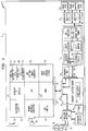
  • Figures 1 and 2 set forth the electronic architecture for a mail processing system 1. Mail processing system 1 includes a meter vault 3, a mailing machine 5 (shown schematically in block form), a printhead control and security module 7, a printer junction board 9, and a plurality of printheads 11 which are ganged together, in the preferred embodiment, to form a single printing unit. The plurality of ganged printheads 11 are used to improve printing speed and thereby increase the mailpiece throughput. However, the invention is equally applicable to a single printhead structure.
    As previously discussed, mailing machine 5 is a structure which is well known in the art and includes for the purposes of this specification any type of mail handling structure which transports and feeds an item of mail to printheads 11 for printing of a postal indicia. Examples of known mail handling machines can be found in United States Patent Numbers 5,467,709 and 5,544,579 which are each incorporated herein by reference. In Figure 1, a mailpiece feeder is shown schematically at 10.
    Regarding printheads 11, they are movably mounted within mail handling machine 5 to be movable between a fixed printing position, a tape printing position, and a maintenance station position where servicing of printheads 11 is accomplished in a known manner. An example of the structure for moving printheads 11 is set forth in the aforementioned United States Patent No. 5,467,709. Accordingly, in operation, when printheads 11 have been moved to the printing position, mailing machine 5 feeds individual mailpieces, via feeder 10, beneath printheads 11 which are energized in synchronization with mailpiece movement to print the postal indicia on the mailpiece. In the preferred embodiment, printheads 11 are ink jet printheads and can either be of the bubble jet type or the piezo actuated type.
    Postage meter vault 3 includes a securely sealed housing 12 within which a conventional meter vault accounting circuit 13 is contained. Additionally, the secure meter vault module 3 includes a keyboard/display device 15 mounted in an exterior surface of the sealed housing 12 for use as will be discussed in more detail below. The sealed housing 12 also has a first external connector 17 to permit electronic interface between meter vault 3 and an external interface unit (EIU)19, and a second external connector 21 to permit connection to a complementary connector 23 extending from printer junction board 9. Thus, by way of the connectors 21, 23 and printer junction board 9, meter vault 3 communicates with and receives d.c. power from mailing machine 5 via mailing machine microcontroller 25. Additionally, by way of printer junction board 9, meter vault 3 communicates with printhead controller and security module 7 for driving printheads 11.
    When meter vault 3 receives d.c. power from mailing machine 5 a linear voltage regulator 29 conditions the d.c. power coming from mailing machine 5 to provide the required logic power for meter vault 3. Alternatively, when meter vault 3 is removed from mailing machine 5, a battery 31 and a battery regulator circuit 33 provide the logic power required by meter vault 3 to support meter inspections and refill operations. The same inspections and refill operations can also be accomplished, in a conventional manner, when meter vault 3 is installed in mailing machine 5 utilizing a modem 27 in communication with meter vault 3 via a connector 28, microcontroller 25, printer junction board 9 and connectors 21, 23. Meter vault keyboard/display 15 is used to permit communication between an operator and meter vault 3 for the purpose of inspections and refills when meter vault 3 is not connected in mailing machine 5. Furthermore, power for printheads 11 can either be provided by mailing machine 5 via printer junction board 9 or from a separate power supply 30.
    Mailing machine 5 includes its own keyboard/display 41 through which a mailing system operator communicates with mailing machine microcontroller 25 to initiate desired postage transactions and inspection operations. Accordingly, when meter vault 3 is removably mounted in mailing machine 5 to printer junction board 9, operator input and output of meter vault 3 is handled by keyboard/display 41 and not via the meter vault keyboard/display 15. Messages received by meter vault 3 from mailing machine 5 are received by a central processing unit (CPU) 51. CPU 51, utilizing programs stored in associated non-volatile memory (NVM) 52, responds to the message received from mailing machine 5 after having taken the appropriate action requested by mailing machine 5. In a basic meter operation, where an operator has requested, via the mailing machine keyboard display 41, that postage be dispensed, CPU 51 checks a descending register within accounting circuit 13. If the desired postage is available, CPU 51 initiates a security protocol with printhead controller/security module 7, reduces the descending register by the desired postage amount and generates and sends the postal indicia image data to printhead controller/security module 7.
    Meter vault 3 also includes a Digital Encryption Standard (DES) engine 64 to support the encrypted communications between the printer controller/security module 7 and meter vault 3 as well as to generate digital tokens in the indicia which are used by the postal service and the meter vendor to authenticate the printed indicia. NVM 52 additionally has a printer controller/security module master key stored therein which is used by CPU 51 as part of a security protocol, as discussed in more detail below, to verify that the printer controller/security module 7 is an authorized device prior to dispensing postage. In a preferred embodiment, the printer controller/security module master key is not stored in the clear but is stored in encrypted form for additional security. The encrypted printer controller/security module master key is encrypted utilizing a second key stored in NVM 52, which second key is different for each meter vault 3 thereby minimizing the security impact to a family of meters if the second key of a particular meter is compromised.
    As an alternative to the dual key structure described above, a unique printer controller/security module key for each meter vault and printer controller/security module combination is loaded into meter vault 3 by remotely interfacing through modem 27 with a remote key management data center. However, in this scenario, if the printer controller/security module 7 were integrally formed as part of printheads 11, a call to the data center would have to be made each time the printheads 11 were changed. By making printer/controller module 7 a separate removable unit which is mounted in mailing machine 5 via connectors 59, 65 to printer junction board 9 and to print heads 11 via a flexible cable 66 to accommodate for the previously discussed movement of printheads 11, printheads 11 can be replaced without requiring a call to the data center. A data center call would only be required when a new meter vault and printer controller/security module combination is encountered. One skilled in the art will recognize that alternatively, as shown in Figure 2, printer controller/security module 7 can be releasably directly connected via connectors 67 to printheads 11 while being connected to printer junction board 9 via a flexible cable 68. In this configuration, printheads 11 plug into printer controller/security module 7 which itself is mounted to a printhead carriage 69 which carriage 69 is moved between the printing, tape, and maintenance positions. For further security, the printer controller/security module 7 and connector 67 can be physically secured by being embedded in epoxy such that once printheads 11 are plugged into connectors 67, access to printer controller/security module 7 is essentially prevented. Thus, in either of the above-discussed embodiments, replacement of printheads 11 becomes a simple operation and precludes requiring a data center call for key management each time a printhead is replaced. It is also to be noted that any of the flexible cable connections discussed above can be a quick disconnect type of connector which allows for the easy replacement of the following individual functional modules: vault meter 3, printer junction board 9, printer controller/security module 7, and printheads 11.
    Communication between meter vault 3 and a graphics interface box 71 permits the graphics resident in a vault flash memory 73 to be updated in the field. That is, image data for any fixed portions of an inscription, a slogan, and the postal indicia are stored in flash memory 73 together with fonts for variable data that may be required in each of these images. A draw on the fly bit map image generator 75, which is more fully described in United States Patent No. 5,651,103 entitled MAIL HANDLING APPARATUS AND PROCESS FOR PRINTING AN IMAGE COLUMN-BY-COLUMN IN REAL TIME, receives from CPU 51 authorization to print the desired postage together with any required variable data. Image generator 75 accesses flash memory 73 and builds the data image as a column-by-column bit stream which is ultimately provided to the driver circuits 77 of printheads 11 to produce the desired image in synchronization with relative movement between the mailpiece and printheads 11. Thus, if additional slogans, inscriptions, or indicia graphics for a different vendor-supplied printhead are desired, they can be downloaded from graphics interface box 71 to flash memory 73. However, in order to prevent the unauthorized downloading of graphics into postage meter 1, all of the graphics in graphics interface box 71 are either signed or encrypted in a known manner. A memory decoder circuit 71 decrypts the graphics data prior to its download into flash memory 73.
    The bit map image data generated by image generator 75 is ciphered at data stream circuitry 79 rather than being sent in the clear to printer controller/security module 7. This provides a second level of security in addition to the security protocol which takes place between meter vault 3 and printer controller/security module 7. In a preferred embodiment, a session key negotiated by meter vault 3 and printer controller/security module 7 as part of the security protocol is used as part of the ciphering of the bit map image data. Printer controller/security module 7 receives and deciphers the bit map data and reformats the data for the specific drivers 77.
    As previously discussed, connector 17 is utilized to connect meter vault 3 to external interface unit 19 when meter vault 3 is operated off of mailing machine 5 to paramatize meter vault 3 for manufacturing and service diagnostics. When meter vault 3 is mounted in mailing machine 5 to printer junction board 9, printer junction board 9 routes the EIU connection to a connector 81 on a back portion of mailing machine 5 to support an external interface unit 83 which is connected to connector 81. EIU 83 will receive power regulated by printer junction board 9. However, EIU 19 must supply its own power.
    Printer controller/security module 7 includes a microcontroller 85 which sends to and receives from meter vault 3 encrypted information. Meter CPU 51 and microcontroller 85 each have the required keys stored therein to permit decrypting and utilization of the encrypted information passed therebetween. Software in microcontoller 85 supports DES encryption and decryption operations and a small amount of EEPROM 87 in microcontroller 85 is required to compute random numbers needed for executing a successful security protocol with meter vault 3. That is, when a postage transaction is requested by an operator via mailing machine keyboard 41, and CPU 51 has determined that the desired postage is available in the meter, a security protocol occurs between CPU 51 and microcontroller 85 prior to authorizing printing of the indicia. The security protocol between CPU 51 and microcontroller 85 can be done in a conventional manner and typically involves the exchange of encrypted data as a way of authenticating both meter vault 3 and printer controller/security module 7. One such security protocol is set forth in the previously mentioned U.S. Patent No. 4,900,903.
    Upon successful completion of the security protocol, printer controller/security module 7 generates and sends to CPU 51 data, which may be ciphered or not ciphered. The data is then used at image data stream cipher block circuitry 79 to cipher the bit map image data generated by bit map image generator 75. The ciphered data could be encrypted or scrambled or a combination of both. The important point is that the bit map image data is not sent in the clear from meter vault 3 to printer controller/security module 7. The ciphered bit map image data is sent via printer junction board 9 to shift register 89 of printer controller/security module 7. The ciphered bit map data is then transferred in parallel to decipher circuitry 91. Decipher circuitry 91 was previously downloaded with a decipher unit and additional data from microcontroller 85 after the successful completion of the security protocol in order to permit deciphering of the ciphered bit map image data in printer controller/security module 7. The ciphered bit map image data is deciphered at decipher circuitry 91 and passed via print buffer 93 to printhead format conversion circuitry 95. Printhead format conversion circuitry 95 reformats the deciphered image data to interface directly with printhead driver circuits 77.
    A mail position decoder 97 provides signals to printhead conversion circuitry 95 which are indicative of the relative position of the mailpiece to the printheads 11 so that synchronized energizing of printheads 11 occurs to produce the desired postal image.
    The modular design of postage meter 1 set forth above permits the easy removal of meter vault 3 and printhead control and security module 7 from mailing machine 5. Each of the connectors 17, 21, 23, 59, 65, and 67 can be standard quick disconnect electrical pin type connectors which facilitate module removal and replacement.
    Additional advantages and modifications will readily occur to those skilled in the art. Therefore, the invention in its broader aspects is not limited to the specific details, and representative devices, shown and described herein. Accordingly, various modifications may be made without departing from the spirit or scope of the general inventive concept as defined by the appended claims.

    Claims (14)

    1. A mailing apparatus comprising:
      a printing mechanism (11) for printing an indication of postage value on a mailpiece;
      a postage meter vault (3) having a securely sealed housing (12), means (51), mounted in the securely sealed housing (12), for accounting for the printed indication of postage value, and an image generator (75) which is mounted in the securely sealed housing (12) and which generates image data corresponding to the indication of postage value to be printed; and
      means (7) for controlling the printing mechanism to print the indication of postage value utilizing the image data generated by the image generator (75).
    2. A mailing apparatus as recited in claim 1, wherein the meter vault (3) further includes within the securely sealed housing (12) means (79) for ciphering the image data generated by the image generator (75) and for sending the ciphered image data to the controlling means (7), and the controlling means includes means (91) for deciphering the ciphered image data and for utilizing the deciphered image data to control printing of the indication of postage value by the printing mechanism (11).
    3. A mailing apparatus as recited in claim 1 or 2, further comprising means (64) for establishing a security protocol between the meter vault (3) and the controlling means (7), and wherein at times when the security protocol has not been established the controlling means (7) will not permit printing of the indication of value.
    4. A mailing apparatus as recited in any one of claims 1 to 3, further comprising a carriage (69) mounted for movement in the apparatus, and wherein the controlling means (7) is mounted on the carriage to be moveable therewith and the printing mechanism (11) is removably mounted on the controlling means (7).
    5. A mailing apparatus as recited in any one of the preceding claims, wherein the printing mechanism (11) is an ink jet printer.
    6. A mailing system comprising:
      a base (5) having a printing mechanism (11) mounted therein, means (10) for feeding a mailpiece to the printing mechanism (11), and a microcontroller (25) for controlling the feeding means (10), wherein the printing mechanism is operable to print an indication of postage value on the mailpiece;
      a plug-in meter vault module (3) having a securely sealed housing (12), accounting circuitry (51,52) mounted in the securely sealed housing, and a first plug-in connector (21); and
      a plug-in printing mechanism controller and security module (7) for securely controlling printing operation of the printing mechanism (11) based on data received from the plug-in meter vault module (3), the plug-in printing mechanism controller and security module (7) including a second plug-in connector (65);
         wherein the first and second plug-in connectors are removably mounted in the base in respective third and fourth complementary plug-in connectors (23,59) to permit electrical communication between the plug-in meter vault module (3), the microcontroller (25), and the plug-in printing mechanism controller and security module (7) while allowing for easy removal of the plug-in meter vault module (3) and the plug-in printing mechanism controller and security module (7) from the base (5).
    7. A mailing system as recited in claim 6, wherein the plug-in meter vault module (3) and the plug-in printing mechanism controller and security module (7) are removably mounted in the base (5) without being directly mechanically coupled to each other.
    8. A mailing system as recited in claim 7, further comprising a printer junction board (9) which is mounted in the base (5) in electrical communication with the microcontroller (25), the printer junction board (9) including the third and fourth complementary plug-in connectors (23,59) such that all electrical communication between the microcontroller (25), the plug-in meter vault (3) and the plug-in printer controller and security module (7) occurs via the printing mechanism junction board (9).
    9. A mailing system as recited in claim 8, wherein the printer junction board (9) is mounted to the base (5) via a plug-in electrical interface.
    10. A mailing system as set forth in claim 9, wherein the printing mechanism (11) has a quick disconnect electrical interface (67) with the plug-in printing mechanism controller and security module (7).
    11. A mailing system comprising:
      a mailing machine (5) having a printing mechanism (11) for printing an indication of postage value on a mailpiece and means for controlling relative movement between the printing mechanism (11) and the mailpiece to ensure the mailpiece is properly positioned relative to the printing mechanism (11) during printing of the indication of postage value;
      a meter vault (3) having a securely sealed housing (12), and means (51), within the securely sealed housing (12), for accounting for the printed indication of postage value, wherein the meter vault (3) is removably mounted in the mailing machine (5) for easy removal via a plug-in connector (21); and
      a printing mechanism control module (7) for securely controlling printing by the printing mechanism (11) based on data received from the meter vault (3), the printing mechanism control module (7) being removably mounted in the mailing machine (5) for easy removal via a quick disconnect connector (65);
         wherein the meter vault (3) and the printing mechanism control module (7) are in electrical communication via the mailing machine (5).
    12. A mailing system as set forth in claim 11, wherein the meter vault (3) further comprises means (75), within the securely sealed housing (12), for creating a bit map image of the indication of value, and wherein the printing mechanism control module (7) is connected to receive the bit map image from the meter vault (3) and is arranged to utilize the bit map image to control the printing mechanism (11) to print the indication of postage value on the mailpiece.
    13. A mailing system as set forth in claim 12, wherein the meter vault (3) and the printing mechanism control module (7) are operable to execute a security protocol therebetween prior to the meter vault (3) sending the bit map image to the printing mechanism control module (7).
    14. A mailing system as set forth in claim 13, wherein the meter vault (3) further includes means (79) for ciphering the bit map image which is sent to the printing mechanism control module (7) based on data received from the printing mechanism control module (7), and the printing mechanism control module (7) has means (91) for deciphering the ciphered bit map image data.
    EP97116466A 1996-09-30 1997-09-22 Modular mailing system Withdrawn EP0833280A3 (en)

    Applications Claiming Priority (2)

    Application Number Priority Date Filing Date Title
    US08/724,131 US5898785A (en) 1996-09-30 1996-09-30 Modular mailing system
    US724131 1996-09-30

    Publications (2)

    Publication Number Publication Date
    EP0833280A2 true EP0833280A2 (en) 1998-04-01
    EP0833280A3 EP0833280A3 (en) 2000-06-28

    Family

    ID=24909147

    Family Applications (1)

    Application Number Title Priority Date Filing Date
    EP97116466A Withdrawn EP0833280A3 (en) 1996-09-30 1997-09-22 Modular mailing system

    Country Status (3)

    Country Link
    US (1) US5898785A (en)
    EP (1) EP0833280A3 (en)
    CA (1) CA2215451C (en)

    Cited By (1)

    * Cited by examiner, † Cited by third party
    Publication number Priority date Publication date Assignee Title
    US6427139B1 (en) * 1999-12-30 2002-07-30 Pitney Bowes Inc. Method for requesting and refunding postage utilizing an indicium printed on a mailpiece

    Families Citing this family (8)

    * Cited by examiner, † Cited by third party
    Publication number Priority date Publication date Assignee Title
    US6144950A (en) * 1998-02-27 2000-11-07 Pitney Bowes Inc. Postage printing system including prevention of tampering with print data sent from a postage meter to a printer
    WO2001084435A1 (en) * 2000-04-28 2001-11-08 Sheldon Margolis Apparatus for converting an envelope feeding machine into an internet connected postage machine
    US20020178130A1 (en) 2001-02-23 2002-11-28 Christian Moy Letter flow control
    US20020133471A1 (en) * 2001-02-23 2002-09-19 Fetneh Eskandari Configuration enablement of franking system
    US20020169728A1 (en) * 2001-02-23 2002-11-14 Christian Moy Modular franking system
    US7769700B1 (en) * 2002-08-15 2010-08-03 Pitney Bowes Inc. Method and apparatus for transferring post meter data
    US6692168B1 (en) * 2003-04-15 2004-02-17 Pitney Bowes Inc Method and system for secure printing of images
    US8019696B2 (en) * 2003-12-23 2011-09-13 Pitney Bowes Inc. Method and system to protect and track data from multiple meters on a removable storage medium

    Citations (6)

    * Cited by examiner, † Cited by third party
    Publication number Priority date Publication date Assignee Title
    US4813912A (en) * 1986-09-02 1989-03-21 Pitney Bowes Inc. Secured printer for a value printing system
    US4858138A (en) * 1986-09-02 1989-08-15 Pitney Bowes, Inc. Secure vault having electronic indicia for a value printing system
    US4864618A (en) * 1986-11-26 1989-09-05 Wright Technologies, L.P. Automated transaction system with modular printhead having print authentication feature
    US5106321A (en) * 1989-12-08 1992-04-21 Alcatel Satman Postage meter having a removable franking head
    EP0717375A2 (en) * 1994-12-15 1996-06-19 Pitney Bowes Inc. Postage accounting system including means for transmitting a bit-mapped image of variable information for driving an externel printer
    EP0718802A2 (en) * 1994-12-22 1996-06-26 Pitney Bowes Inc. Preventing monitoring of data remotely sent from a metering accounting vault to digital printer

    Family Cites Families (17)

    * Cited by examiner, † Cited by third party
    Publication number Priority date Publication date Assignee Title
    US5007083A (en) * 1981-03-17 1991-04-09 Constant James N Secure computer
    US4775246A (en) * 1985-04-17 1988-10-04 Pitney Bowes Inc. System for detecting unaccounted for printing in a value printing system
    US4835713A (en) * 1985-08-06 1989-05-30 Pitney Bowes Inc. Postage meter with coded graphic information in the indicia
    US4802218A (en) * 1986-11-26 1989-01-31 Wright Technologies, L.P. Automated transaction system
    US4900903A (en) * 1986-11-26 1990-02-13 Wright Technologies, L.P. Automated transaction system with insertable cards for transferring account data
    CA1301335C (en) * 1988-02-08 1992-05-19 Robert K.T. Chen Postage meter value card system
    US4908502A (en) * 1988-02-08 1990-03-13 Pitney Bowes Inc. Fault tolerant smart card
    US4949381A (en) * 1988-09-19 1990-08-14 Pitney Bowes Inc. Electronic indicia in bit-mapped form
    GB8908391D0 (en) * 1989-04-13 1989-06-01 Alcatel Business Systems Detachable meter module
    US5189700A (en) * 1989-07-05 1993-02-23 Blandford Robert R Devices to (1) supply authenticated time and (2) time stamp and authenticate digital documents
    WO1993006695A1 (en) * 1991-09-23 1993-04-01 Z-Microsystems Enhanced security system for computing devices
    US5544579A (en) * 1992-12-17 1996-08-13 Pitney Bowes Inc. Mailing machine including overrideable sheet length discriminating structure
    GB9401789D0 (en) * 1994-01-31 1994-03-23 Neopost Ltd Franking machine
    US5467709A (en) * 1994-12-22 1995-11-21 Pitney Bowes Inc. Mailing machine utilizing ink jet printer
    US5583970A (en) * 1995-02-28 1996-12-10 Pitney Bowes Inc. Printer command set for controlling address and postal code printing functions
    US5684949A (en) * 1995-10-13 1997-11-04 Pitney Bowes Inc. Method and system for securing operation of a printing module
    US5696829A (en) * 1995-11-21 1997-12-09 Pitney Bowes, Inc. Digital postage meter system

    Patent Citations (6)

    * Cited by examiner, † Cited by third party
    Publication number Priority date Publication date Assignee Title
    US4813912A (en) * 1986-09-02 1989-03-21 Pitney Bowes Inc. Secured printer for a value printing system
    US4858138A (en) * 1986-09-02 1989-08-15 Pitney Bowes, Inc. Secure vault having electronic indicia for a value printing system
    US4864618A (en) * 1986-11-26 1989-09-05 Wright Technologies, L.P. Automated transaction system with modular printhead having print authentication feature
    US5106321A (en) * 1989-12-08 1992-04-21 Alcatel Satman Postage meter having a removable franking head
    EP0717375A2 (en) * 1994-12-15 1996-06-19 Pitney Bowes Inc. Postage accounting system including means for transmitting a bit-mapped image of variable information for driving an externel printer
    EP0718802A2 (en) * 1994-12-22 1996-06-26 Pitney Bowes Inc. Preventing monitoring of data remotely sent from a metering accounting vault to digital printer

    Cited By (1)

    * Cited by examiner, † Cited by third party
    Publication number Priority date Publication date Assignee Title
    US6427139B1 (en) * 1999-12-30 2002-07-30 Pitney Bowes Inc. Method for requesting and refunding postage utilizing an indicium printed on a mailpiece

    Also Published As

    Publication number Publication date
    EP0833280A3 (en) 2000-06-28
    CA2215451A1 (en) 1998-03-30
    CA2215451C (en) 2003-11-25
    US5898785A (en) 1999-04-27

    Similar Documents

    Publication Publication Date Title
    US4813912A (en) Secured printer for a value printing system
    US5606613A (en) Method for identifying a metering accounting vault to digital printer
    EP0881600B1 (en) Synchronization of cryptographic keys between two modules of a distributed system
    CA1259704A (en) System for detecting unaccounted for printing in a value printing system
    EP0825565B1 (en) Electronic postage meter system separable printer and accounting arrangement incorporating partition of indicia and accounting information
    CA2193028C (en) Method and apparatus for securely authorizing performance of a function in a distributed system such as a postage meter
    EP0825561B1 (en) Electronic postage meter system having internal accounting system and removable external accounting system
    EP0862142B1 (en) Franking machine
    EP1001381B1 (en) Method and apparatus for dynamically determining a printing location in a document for a postage indicia
    EP0825562B1 (en) Method and apparatus for remotely changing security features of a postage meter
    EP0775984A2 (en) Digital postage meter system having a replaceable printing unit with system software upgrade
    CA2215451C (en) Modular mailing system
    US6029137A (en) Updating domains in a postage evidencing system
    US6188997B1 (en) Postage metering system having currency synchronization
    US6456987B1 (en) Personal computer-based mail processing system with security arrangement contained in the personal computer
    US6178412B1 (en) Postage metering system having separable modules with multiple currency capability and synchronization
    US6477511B1 (en) Method and postal apparatus with a chip card write/read unit for reloading change data by chip card
    US6466922B1 (en) Postage meter with removable print head and having means to control access to the print head
    US5655024A (en) Method of tracking postage meter location
    US6692168B1 (en) Method and system for secure printing of images
    AU750360B2 (en) Postage printing system having secure reporting of printer errors

    Legal Events

    Date Code Title Description
    PUAI Public reference made under article 153(3) epc to a published international application that has entered the european phase

    Free format text: ORIGINAL CODE: 0009012

    AK Designated contracting states

    Kind code of ref document: A2

    Designated state(s): DE FR GB

    PUAL Search report despatched

    Free format text: ORIGINAL CODE: 0009013

    AK Designated contracting states

    Kind code of ref document: A3

    Designated state(s): AT BE CH DE DK ES FI FR GB GR IE IT LI LU MC NL PT SE

    17P Request for examination filed

    Effective date: 20001221

    AKX Designation fees paid

    Free format text: DE FR GB

    17Q First examination report despatched

    Effective date: 20070124

    STAA Information on the status of an ep patent application or granted ep patent

    Free format text: STATUS: THE APPLICATION HAS BEEN WITHDRAWN

    18W Application withdrawn

    Effective date: 20100520