EP0836097A2 - Measuring probe - Google Patents
Measuring probe Download PDFInfo
- Publication number
- EP0836097A2 EP0836097A2 EP97117312A EP97117312A EP0836097A2 EP 0836097 A2 EP0836097 A2 EP 0836097A2 EP 97117312 A EP97117312 A EP 97117312A EP 97117312 A EP97117312 A EP 97117312A EP 0836097 A2 EP0836097 A2 EP 0836097A2
- Authority
- EP
- European Patent Office
- Prior art keywords
- tip unit
- measuring tip
- needles
- line
- coplanar line
- Prior art date
- Legal status (The legal status is an assumption and is not a legal conclusion. Google has not performed a legal analysis and makes no representation as to the accuracy of the status listed.)
- Granted
Links
Images

Classifications
-
- G—PHYSICS
- G01—MEASURING; TESTING
- G01R—MEASURING ELECTRIC VARIABLES; MEASURING MAGNETIC VARIABLES
- G01R1/00—Details of instruments or arrangements of the types included in groups G01R5/00 - G01R13/00 and G01R31/00
- G01R1/02—General constructional details
- G01R1/06—Measuring leads; Measuring probes
- G01R1/067—Measuring probes
- G01R1/06772—High frequency probes
Definitions
- the invention relates to a probe unit for contacting planar Microwave circuits.
- measuring tip units for microwave wafer measuring devices known in which the to the measuring device, for example a vectorial Network analyzer, leading coaxial cable passes directly into contact tips (US Patent 4,871,964 or company publication "Pico-Probe” from GGB Industries, Inc.).
- the inner conductor of the coaxial cable is extended beyond the outer conductor to the end pointed and bent down like a claw.
- On the outer conductor of the coaxial cable is at least on one side a claw-shaped downward curve Contact spring attached.
- the actual measuring tip consists of a triangular dielectric substrate the back of which is a coplanar line.
- the one carrying the coplanar line Substrate is relatively sensitive to wear and breakage.
- the Probe unit under the microscope the measuring point is relatively large area by the Substrate covered, only the ends of the coplanar line are visible, the adjustment is therefore very difficult and imprecise.
- the measuring tips Due to the design of the measuring tips as needles made of elastic spring steel material, a The measuring tips are practically impossible to break off, the needles are also essential more durable and do not wear out as quickly and therefore need to be replaced less often.
- the measuring tips only the connection between the needles and the Coplanar line can be solved, and then only the pure wear part be replaced.
- the measuring tips in the form of needles can be viewed under a microscope be placed very precisely on the measuring point of the microwave circuit, since between the needles have a clear view and the microwave circuit also below Needles remains visible.
- the between coaxial line connection and contact tips intermediate coplanar line enables the simple construction of universally applicable measuring tip units with the most diverse properties, which are required for special applications.
- an impedance transformation circuit into the coplanar line of the housing any input impedance between the contact tips can be produced as this for special measuring tasks can be advantageous.
- any passive in the housing in the coplanar line and / or even integrated active microwave circuits are, for example, parts of the measuring tip unit connected measuring devices.
- transition from the coaxial line connection to the Coplanar conduction can be used using conventional known transitions connector designs are preferred used according to the subclaims, which not only are suitable for measuring tip units, but the in this simple and inexpensive version also as Transition plug from coaxial lines to coplanar lines are suitable for other applications.
- coplanar lines are microwave lines understood where all striplines are formed on the same side of the substrate, that is for example one of three arranged side by side
- Stripline existing symmetrical coplanar line (coplanar three-band cable) or symmetrical or unbalanced two-band lines, such as criz Zinke / Brunswig, high frequency technology 1, 5th edition, Page 157, Fig. 4.7 / 1e, f and g are shown.
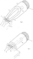
- FIG. 1 shows an enlarged perspective view a measuring tip unit E according to the invention consisting of a flat with the cover removed Metal housing 1 and one formed on one end face Coaxial line connection 2 in the form of a coaxial connector, on which a measuring device, not shown, for example a network analyzer, leading coaxial cable is screwable.
- a Microwave substrate 3 attached, on which a coplanar line 4 is formed, which is different from one Coaxial line connection 2 facing end of the Housing extends to the opposite end.
- this is a coplanar line trained as a three-band line and consists of a central strip line 5 and through slots thereof separate side ground strip conductors 6 and 7.
- the Coaxial line connection 2 merges into three side by side arranged terminal lugs 8, 9, 10, the middle Terminal lug 8 is with the inner conductor and the side Terminal lugs 9 and 10 are connected to the outer conductor of the Coaxial line connection 2 connected.
- These connecting flags 8, 9, 10 protrude through an opening in the front wall of the housing 1 inside and lie flat with pressure the surface of the stripline 5, 6 and 7 of the coplanar line on. If the contact by pressure is not is sufficient, the connection lugs with the strip conductors also electrically by soldering or bond wires be connected.
- the housing 1 In the end face opposite the coaxial connector 2 the housing 1 is formed an opening 11 through which three spaced thin next to each other Protruding needles 12 from the inside of the housing. in the These needles 12 with the three strip conductors are the housing 5, 6, 7 of the coplanar line. Details of this The needle arrangement shows the enlarged sectional view Fig. 2.
- the needles 12 are side by side in one body 13 made of insulating material, which has a retaining ring 14 is releasably attached in the opening 11 of the housing.
- the needles have a rectangular or round cross-section and are slightly conical, their thinner exterior End 16 and their thicker inner end is respectively chiselled.
- the needles 12 are also with their ends 16 converging in the body 13 used so that the tips 16 for contacting with the microwave circuit M to be measured possess a small distance of only a few um while the ends lying in the housing through the stripline 5, 6, 7 of the coplanar line have a predetermined distance.
- the mutual conical distance between the needles 12 and her conical diameter is taking into account the Dielectric constant of the insulating body 13 selected so that between the tips 16 of the needles 12 one for the There is predetermined impedance in each application.
- the chisel-shaped bevel of the tips 16 is also chosen so that at a slope shown in Fig. 2 Put on the measuring tip unit E the needle ends Surface contact with the areas to be contacted Establish microwave circuit M.
- the diameter of the needles at the thicker end lies, for example, between 0.5 and 1 mm and on the outside pointed end between 50 to 100 ⁇ m.
- the probe unit E has an input impedance of 50 ⁇ and is therefore for measurements in 50 ⁇ systems suitable.
- a measuring tip unit E according to FIG. 1 can, however also easily to other input impedances be converted between the measuring tips. It is for that only required in the coplanar line 5, 6, 7 for example in the middle of a corresponding impedance transformation circuit to install and the distances of the Needles 12 according to this desired impedance choose. In this way, for example, between the Probe tips have an input impedance in the range of a few ⁇ to a few k ⁇ can be selected while connecting to the measuring device continues via a 50 ⁇ coaxial cable.
- a coplanar line could also consist of only two strip conductors existing symmetrical or asymmetrical Coplanar line can be provided in the housing, in this case, only two needles 12 are also provided a symmetrical or asymmetrical two-point measurement signal recording enable.
- the housing 1 of the probe unit E can optionally other passive and / or active circuits installed are required for the operation of the measuring tip unit will.
- the substrate 3 Circuits for direct voltage supply via the measuring tips be provided to the test object, which is on the side cables led out on the housing with external arranged Devices are connected.
- FIG. 3 Another possibility, as with an inventive Probe unit E directly circuit parts of a vectorial network analyzer in the probe assembly can be integrated, Fig. 3.
- the Measurement setup for measuring a measurement object 21, for example a voltage amplifier for high frequencies, by means of of a vector network analyzer 22 is shown.
- measuring points m1 integrated up to m4 of the network analyzer.
- These measuring points consist, for example, of frequency-converting components such as mixers, amplifiers, analog / digital converters and the like active and passive components that thus via the coplanar line as close as possible to the measurement object are switched on, which is particularly important for measurements in Maximum frequency range is an advantage.
- additional other assemblies such as generators, noise sources or the like, which are then integrated in the immediate vicinity of the object to be measured with the coplanar line are connected and, if necessary, from the Housing leads leading to the outside with other devices are connected.
- FIG. 3 also shows how by Impedance transformation circuits in the form of resistor networks 23 and 24 in the probe units E1 and E2 are integrated, the most appropriate Input impedances between the probe tips 12 can be selected with which the corresponding inputs and Output connections of the measurement object 21 can be contacted.
- the distance is Contact tips of the probe unit E1 and the impedance transformation circuit 23 dimensioned so that between the needles 12 have an input impedance of less than 100 ⁇ prevails, even though the probe unit E1 has a 50 ⁇ coaxial cable connected to the network analyzer 22 is.
- the probe tips of unit E2 are therefore arranged at a correspondingly greater distance from each other and the impedance transformation network 24 dimensioned so that an input impedance of, for example 10 k ⁇ exists.
- FIG. 4 and 5 show embodiments according to the invention for the transition from a coaxial line connection 2 to a coplanar line.
- Fig. 4 shows the transition to a symmetrical three-strip line coplanar line
- Fig. 5 shows the transition to an asymmetrical two-strip line coplanar line.
- the outer conductor 30 of the coaxial line connection 2 split and runs out in two opposite, gradually tapering triangular Sections 31, 32, the ends 35, 36 also light are turned towards each other.
- the inner conductor 34 is tapered. This shape of the exterior and Inner conductor is achieved that on the coaxial side Gradually end radially symmetrical electromagnetic field passes into the field distribution of a coplanar line, that between the tapered ends 35, 36 of the opposite Outer conductor sections 31, 32 and that in one Flat tapered end 37 of the inner conductor is formed.
- the ends 35, 36, 37 are via connecting lugs 8, 9, 10 directly with those on the substrate 3 trained strip conductors 5, 6, 7 of the coplanar line 4 connected.
Abstract
Description
Die Erfindung betrifft eine Meßspitzeneinheit zum Kontaktieren von planaren Mikrowellenschaltungen.The invention relates to a probe unit for contacting planar Microwave circuits.
Es sind Meßspitzeneinheiten für Mikrowellen-Wafer-Meßeinrichtungen (Wafer-Prober) bekannt, bei denen das zum Meßgerät, beispielsweise einem vektoriellen Netzwerkanalysator, führende Koaxialkabel unmittelbar in Kontaktspitzen übergeht (US Patent 4 871 964 bzw. Firmendruckschrift "Pico-Probe" der Firma GGB Industries, Inc.). Der Innenleiter des Koaxialkabels ist über den Außenleiter hinaus verlängert, zum Ende hin zugespitzt und krallenförmig nach unten gebogen. Am Außenleiter des Koaxialkabels ist mindestens auf einer Seite eine ebenfalls krallenförmig nach unten gebogene Kontaktfeder befestigt. Diese bekannten Meßspitzen verschleißen bei Gebrauch relativ schnell innerhalb von Monaten, es besteht außerdem die Gefahr, daß durch Fehlsteuerungen beim Aufsetzen der Meßspitzen diese brechen. Dann muß die gesamte Meßspitzeneinheit ausgetauscht und erneuert werden.They are measuring tip units for microwave wafer measuring devices (wafer probers) known in which the to the measuring device, for example a vectorial Network analyzer, leading coaxial cable passes directly into contact tips (US Patent 4,871,964 or company publication "Pico-Probe" from GGB Industries, Inc.). The inner conductor of the coaxial cable is extended beyond the outer conductor to the end pointed and bent down like a claw. On the outer conductor of the coaxial cable is at least on one side a claw-shaped downward curve Contact spring attached. These known measuring tips wear out relatively in use quickly within months, there is also a risk that through Incorrect controls when attaching the measuring tips break them. Then the whole Probe tip unit can be replaced and replaced.
Ähnliches gilt für eine andere bekannte Meßspitzeneinheit, bei der die Meßspitzen in koplanarer Leitungstechnik ausgebildet sind (Europäische Patentschrift 0 367 542). Die eigentliche Meßspitze besteht aus einem dreieckförmigen dielektrischen Substrat, auf dessen Rückseite eine Koplanarleitung ausgebildet ist. Das die Koplanarleitung tragende Substrat ist relativ empfindlich gegen Verschleiß und Bruch. Beim Justieren der Meßspitzeneinheit unter dem Mikroskop wird die Meßstelle relativ großflächig durch das Substrat abgedeckt, es sind nur die Enden der Koplanarleitung sichtbar, die Justierung ist daher sehr erschwert und ungenau.The same applies to another known measuring tip unit, in which the measuring tips in coplanar line technology are trained (European Patent Specification 0 367 542). The The actual measuring tip consists of a triangular dielectric substrate the back of which is a coplanar line. The one carrying the coplanar line Substrate is relatively sensitive to wear and breakage. When adjusting the Probe unit under the microscope, the measuring point is relatively large area by the Substrate covered, only the ends of the coplanar line are visible, the adjustment is therefore very difficult and imprecise.
Es ist Aufgabe der Erfindung, eine Meßspitzeneinheit zu schaffen, die einfach und preiswert herstellbar, unempfindlich gegen Beschädigungen und verschleißarm ist und trotzdem einfach handbabbar und universell einsetzbar ist.It is an object of the invention to provide a probe assembly that is simple and is inexpensive to manufacture, insensitive to damage and low-wear and is still easy to handle and can be used universally.
Diese Aufgabe wird ausgehend von einer Meßspitzeneinheit laut Oberbegriff des Hauptanspruches durch dessen kennzeichnende Merkmale gelöst. Vorteilhafte Weiterbildungen ergeben sich aus den Unteransprüchen. This task is based on a probe unit according to the preamble of Main claim solved by its characteristic features. Beneficial Further training results from the subclaims.
Durch die Ausbildung der Meßspitzen als Nadeln aus elastischem Federstahlmaterial ist ein Abbrechen der Meßspitzen praktisch ausgeschlossen, die Nadeln sind auch wesentlich haltbarer und verschleißen nicht so schnell und müssen daher weniger oft ersetzt werden. Beim Auswechseln der Meßspitzen muß nur die Verbindung zwischen den Nadeln und der Koplanarleitung gelöst werden, und es kann dann nur das reine Verschleißteil ausgewechselt werden. Die Meßspitzen in Form von Nadeln können unterm Mikroskop sehr genau auf die Meßstelle der Mikrowellenschaltung aufgesetzt werden, da zwischen den Nadeln freier Durchblick besteht und die Mikrowellenschaltung auch unterhalb der Nadeln sichtbar bleibt. Due to the design of the measuring tips as needles made of elastic spring steel material, a The measuring tips are practically impossible to break off, the needles are also essential more durable and do not wear out as quickly and therefore need to be replaced less often. When changing the measuring tips only the connection between the needles and the Coplanar line can be solved, and then only the pure wear part be replaced. The measuring tips in the form of needles can be viewed under a microscope be placed very precisely on the measuring point of the microwave circuit, since between the needles have a clear view and the microwave circuit also below Needles remains visible.
Die zwischen Koaxialleitungsanschluß und Kontaktspitzen zwischengeschaltete Koplanarleitung ermöglicht den einfachen Aufbau von universell einsetzbaren Meßspitzeneinheiten mit den verschiedenartigsten Eigenschaften, die jeweils für spezielle Anwendungsfälle gewünscht werden. So kann beispielsweise durch Einbau einer Impedanztransformationsschaltung in die Koplanarleitung des Gehäuses eine beliebige Eingangsimpedanz zwischen den Kontaktspitzen hergestellt werden, wie dies für spezielle Meßaufgaben vorteilhaft sein kann. Es besteht sogar die Möglichkeit, daß im Gehäuse in die Koplanarleitung beliebige passive und/oder sogar aktive Mikrowellenschaltungen integriert werden, also beispielsweise Teile der an die Meßspitzeneinheit angeschlossenen Meßgeräte.The between coaxial line connection and contact tips intermediate coplanar line enables the simple construction of universally applicable measuring tip units with the most diverse properties, which are required for special applications. For example, by installing an impedance transformation circuit into the coplanar line of the housing any input impedance between the contact tips can be produced as this for special measuring tasks can be advantageous. There is even the possibility that any passive in the housing in the coplanar line and / or even integrated active microwave circuits are, for example, parts of the measuring tip unit connected measuring devices.
Für den Übergang vom Koaxialleitungsanschluß auf die Koplanarleitung können übliche bekannte Übergänge benutzt werden, vorzugsweise werden hierfür jedoch Steckerkonstruktionen laut den Unteransprüchen benutzt, die nicht nur für Meßspitzeneinheiten geeignet sind, sondern die in dieser einfachen und preiswerten Ausführung auch als Übergangsstecker von Koaxialleitungen auf Koplanarleitungen für andere Anwendungen geeignet sind.For the transition from the coaxial line connection to the Coplanar conduction can be used using conventional known transitions connector designs are preferred used according to the subclaims, which not only are suitable for measuring tip units, but the in this simple and inexpensive version also as Transition plug from coaxial lines to coplanar lines are suitable for other applications.
Unter Koplanarleitung werden gemäß der Erfindung Mikrowellenleitungen
verstanden, bei denen alle Streifenleiter
auf derselben Seite des Substrats ausgebildet sind, also
beispielsweise eine aus drei nebeneinander angeordneten
Streifenleiter bestehende symmetrische Koplanarleitung
(koplanare Dreibandleitung) bzw. symmetrische oder
unsymmetrische Zweibandleitungen, wie sie beispielsweise
bei Zinke/Brunswig, Hochfrequenztechnik 1, 5. Auflage,
Seite 157, Abb. 4.7/1e,f und g dargestellt sind. According to the invention, coplanar lines are microwave lines
understood where all striplines
are formed on the same side of the substrate, that is
for example one of three arranged side by side
Stripline existing symmetrical coplanar line
(coplanar three-band cable) or symmetrical or
unbalanced two-band lines, such as
bei Zinke / Brunswig,
Die Erfindung wird im folgenden anhand schematischer Zeichnungen an Ausführungsbeispielen näher erläutert.The invention will now be described more schematically Drawings explained in more detail using exemplary embodiments.
Fig. 1 zeigt in vergrößerter perspektivischer Ansicht
eine erfindungsgemäße Meßspitzeneinheit E bestehend aus
einem mit abgenommenem Deckel dargestellten flachen
Metallgehäuse 1 und einem an der einen Stirnseite ausgebildeten
Koaxialleitungsanschluß 2 in Form eines Koaxialsteckers,
an dem ein zu einem nicht dargestellten Meßgerät,
beispielweise einen Netzwerkanalysator, führendes Koaxialkabel
anschraubbar ist. Am Boden des Gehäuses 1 ist ein
Mikrowellensubstrat 3 angebracht, auf dem eine Koplanarleitung
4 ausgebildet ist, die sich von der einen dem
Koaxialleitungsanschluß 2 zugewandten Stirnseite des
Gehäuses bis zur gegenüberliegenden Stirnseite erstreckt.
In dem gezeigten Ausführungsbeispiel ist diese Koplanarleitung
als Dreibandleitung ausgebildet und besteht aus
einem Mittel-Streifenleiter 5 und durch Schlitze davon
getrennten seitlichen Masse-Streifenleitern 6 und 7. Der
Koaxialleitungsanschluß 2 geht über in drei nebeneinander
angeordneten Anschlußfahnen 8, 9, 10, die mittlere
Anschlußfahne 8 ist mit dem Innenleiter und die seitlichen
Anschlußfahnen 9 und 10 sind mit dem Außenleiter des
Koaxialleitungsanschlusses 2 verbunden. Diese Anschlußfahnen
8, 9, 10 ragen durch eine Öffnung in der Stirnwand
des Gehäuses 1 nach innen und liegen mit Druck flach auf
der Oberfläche der Streifenleiter 5, 6 und 7 der Koplanarleitung
auf. Falls die Kontaktgabe durch Druck nicht
ausreicht, können die Anschlußfahnen mit den Streifenleitern
auch noch durch Löten oder Bonddrähte elektrisch
verbunden sein.1 shows an enlarged perspective view
a measuring tip unit E according to the invention consisting of
a flat with the cover removed
In der dem Koaxialstecker 2 gegenüberliegenden Stirnseite
des Gehäuses 1 ist eine Öffnung 11 ausgebildet, durch
welche drei im Abstand nebeneinander angeordnete dünne
Nadeln 12 aus dem Gehäuseinneren nach außen ragen. Im
Gehäuse sind diese Nadeln 12 mit den drei Streifenleitern
5, 6, 7 der Koplanarleitung verbunden. Details dieser
Nadelanordnung zeigt das vergrößerte Schnittbild nach
Fig. 2. Die Nadeln 12 sind nebeneinander in einem Körper
13 aus Isoliermaterial eingesetzt, der über einen Haltering
14 in der Öffnung 11 des Gehäuses lösbar befestigt ist.
Die Nadeln besitzen rechteckigen oder runden Querschnitt
und sind leicht konisch ausgebildet, ihr dünneres äußeres
Ende 16 und ihr dickeres innenliegendes Ende ist jeweils
meißelförmig angeschrägt. Die Nadeln 12 sind außerdem
mit ihren Enden 16 aufeinander zulaufend im Körper 13
eingesetzt, so daß die Spitzen 16 den für die Kontaktierung
mit der zu messenden Mikrowellenschaltung M erforderlichen
geringen Abstand von nur einigen um besitzen, während
die im Gehäuse liegenden Enden den durch die Streifenleiter
5, 6, 7 der Koplanarleitung vorgegebenen Abstand besitzen.
Der gegenseitige konische Abstand der Nadeln 12 und ihr
konischer Durchmesser ist unter berücksichtigung der
Dielektrizitätskonstante des Isolierkörpers 13 so gewählt,
daß zwischen den Spitzen 16 der Nadeln 12 eine für den
jeweiligen Anwendungsfall vorbestimmte Impedanz besteht.
Die meißelförmige Anschrägung der Spitzen 16 ist außerdem
so gewählt, daß bei einem in Fig. 2 dargestellten schrägen
Aufsetzen der Meßspitzeneinheit E die Nadelenden einen
Flächenkontakt mit den zu kontaktierenden Bereichen der
Mikrowellenschaltung M herstellen. Auch die inneren
meißelförmig angeschrägten dickeren Enden der konischen
Nadeln 12 liegen mit Flächenkontakt auf den Oberflächen
der Streifenleiter 5, 6, 7 auf und werden wiederum vorzugsweise
nur durch Druck in Kontakt damit gehalten. Bei
Bedarf kann auch hier eine zusätzliche elektrische Verbindung
beispielsweise in Form von Bonddrähten 15 vorgesehen
sein. Der Durchmesser der Nadeln am dickeren Ende
liegt beispielsweise zwischen 0,5 und 1 mm und am äußeren
spitzen Ende zwischen 50 bis 100 µm.In the end face opposite the
Bei Verschleiß oder Beschädigung der Nadeln wird die aus
den drei Nadeln 12 und dem Körper 13 aus Isoliermaterial
bestehende Kontaktspitzeneinheit K nach Lösen des Halterings
14 einfach aus der Gehäuseöffnung 11 herausgenommen
und durch eine neue Kontaktspitzeneinheit ersetzt, damit
kann bei einer Meßspitzeneinheit E sehr preiswert nur
das Verschleißteil erneuert werden und die teueren Teile
wie Gehäuse, Koplanarleitung und Koaxialstecker werden
beibehalten.In the event of wear or damage to the needles, the
the three
In dem gezeigten Ausführungsbeispiel mit durchgehender
Koplanarleitung 4 zwischen beispielsweise 50 Ω-Koaxialleitungsanschluß
2 und den in einem für eine Eingangsimpedanz
von 50 Ω vorgegebenen Abstand angeordneten Nadeln
12 besitzt die Meßspitzeneinheit E eine Eingangsimpedanz
von 50 Ω und ist damit für Messungen in 50 Ω Systemen
geeignet. Eine Meßspitzeneinheit E nach Fig. 1 kann jedoch
auch auf einfache Weise auf andere Eingangsimpedanzen
zwischen den Meßspitzen umgerüstet werden. Dazu ist es
nur erforderlich, in die Koplanarleitung 5, 6, 7 beispielsweise
in deren Mitte eine entsprechende Impedanztransformationsschaltung
einzubauen und die Abstände der
Nadeln 12 entsprechend dieser gewünschten Impedanz zu
wählen. Auf diese Weise kann beispielsweise zwischen den
Meßspitzen eine Eingangsimpedanz im Bereich von einigen
Ω bis einigen kΩ gewählt werden, während die Verbindung
zum Meßgerät weiterhin über ein 50 Ω Koaxialkabel erfolgt.In the embodiment shown with a continuous
Coplanar line 4 between, for example, 50 Ω
Anstelle der aus drei Streifenleitern 5,6, 7 bestehenden
Koplanarleitung könnte auch eine aus nur zwei Streifenleitern
bestehende symmetrische oder unsymmetrische
Koplanarleitung im Gehäuse vorgesehen sein, in diesem
Fall sind dann auch nur zwei Nadeln 12 vorgesehen, die
eine symmetrische bzw. unsymmetrische Zweipunkt-Meßsignalaufnahme
ermöglichen.Instead of the three
Die Ausbildung der Kontaktspitzen als dünne elastische Nadeln aus einem elastischen Federstahlmaterial gewährleistet, daß die Meßspitzen unter dem Mikroskop sehr genau fokusiert und auf den extrem kleinen Kontaktstellen von nur 10 bis 200 µm der zu vermessenden Mikrowellenschaltung aufgesetzt werden können. Da sie nachgiebig elastisch verformbar sind ist auch ihr Verschleiß minimal und auch die Gefahr des Nadelbruches gering.The formation of the contact tips as thin elastic Guaranteed needles made of an elastic spring steel material that the probe tips under the microscope are very accurate focused and on the extremely small contact points of only 10 to 200 µm of the microwave circuit to be measured can be put on. Because they are resiliently elastic their wear is minimal and also deformable the risk of needle breakage is low.
Im Gehäuse 1 der Meßspitzeneinheit E können gegebenenfalls
auch andere passive und/oder aktive Schaltungen eingebaut
werden, die für den Betrieb der Meßspitzeneinheit benötigt
werden. So können beispielsweise auf dem Substrat 3
Schaltungen zur Gleichspannungszuführung über die Meßspitzen
zum Meßobjekt vorgesehen sein, die über seitlich
am Gehäuse herausgeführte Leitungen mit außen angeordneten
Geräten verbunden sind.In the
Eine andere Möglichkeit, wie bei einer erfindungsgemäßen
Meßspitzeneinheit E unmittelbar Schaltungsteile eines
vektoriellen Netzwerkanalysators in die Meßspitzeneinheit
integriert werden können, zeigt Fig. 3. Hier ist der
Meßaufbau zum Messen eines Meßobjekts 21, beispielsweise
eines Spannungsverstärkers für hohe Frequenzen, mittels
eines vektoriellen Netzwerkanalysators 22 gezeigt.Another possibility, as with an inventive
Probe unit E directly circuit parts of a
vectorial network analyzer in the probe assembly
can be integrated, Fig. 3. Here is the
Measurement setup for measuring a
In den Gehäusen 1 der Meßspitzeneinheiten E1 und E2 sind
unmittelbar die schematisch angedeuteten Meßstellen m1
bis m4 des Netzwerkanalysators integriert. Diese Meßstellen
bestehen beispielsweise aus frequenzumsetzenden Bauelementen
wie Mischer, Verstärker, Analog/Digital-Wandler
und dergleichen aktiven und passiven Bauelementen, die
damit über die Koplanarleitung möglichst nahe am Meßobjekt
angeschaltet sind, was insbesondere für Messungen im
Höchstfrequenzbereich von Vorteil ist. In ähnlicher Weise
können in den Gehäusen der Meßspitzeneinheiten auch
zusätzliche andere Baugruppen wie Generatoren, Rauschquellen
oder dergleichen integriert werden, die dann
unmittelbar in der Nähe des Meßobjekts mit der Koplanarleitung
verbunden sind und die gegebenenfalls über vom
Gehäuse nach außen geführte Zuleitungen mit anderen Geräten
verbunden sind.In the
Der Meßaufbau nach Fig. 3 zeigt außerdem, wie durch
Impedanztransformationsschaltungen in Form von Widerstandsnetzwerken
23 und 24, die in den Meßspitzeneinheiten
E1 und E2 integriert sind, die jeweils zweckmäßigsten
Eingangsimpedanzen zwischen den Meßspitzen der Nadeln
12 wählbar sind, mit denen die entsprechenden Ein- und
Ausgangs-Anschlüsse des Meßobjekts 21 kontaktiert werden.
In dem gezeigten Ausführungsbeispiel ist der Abstand der
Kontaktspitzen der Meßspitzeneinheit E1 und die Impedanztransformationsschaltung
23 so dimensioniert, daß zwischen
den Nadeln 12 eine Eingangsimpedanz von kleiner 100 Ω
herrscht, obwohl die Meßspitzeneinheit E1 über ein 50 Ω-Koaxialkabel
mit dem Netzwerkanalysator 22 verbunden
ist. Ausgangsseitig wird beim Messen des Meßobjekts 21
eine hochohmige Eingangsimpedanz der Meßspitzeneinheit
E2 gewünscht, die Meßspitzen der Einheit E2 sind daher
in einem entsprechend größeren Abstand voneinander angeordnet
und das Impedanztransformationsnetzwerk 24 ist
so dimensioniert, daß eine Eingangsimpedanz von beispielsweise
10 kΩ besteht.3 also shows how by
Impedance transformation circuits in the form of
Fig. 4 und 5 zeigen erfindungsgemäße Ausführungsformen
für den Übergang von einem Koaxialleitungsanschluß 2 auf
eine Koplanarleitung. Fig. 4 zeigt dabei den Übergang
auf eine symmetrische Drei-Streifenleiter-Koplanarleitung,
Fig. 5 zeigt den Übergang auf eine unsymmetrische Zwei-Streifenleiter-Koplanarleitung.4 and 5 show embodiments according to the invention
for the transition from a
Gemäß Fig. 4 ist der Außenleiter 30 des Koaxialleitungsanschlusses
2 gespalten und läuft aus in zwei gegenüberliegenden,
sich allmählich verjüngenden dreieckförmigen
Abschnitten 31, 32, deren Enden 35, 36 außerdem leicht
nach innen aufeinander zu abgebogen sind. Der Innenleiter
34 ist konisch verjüngt. Durch diese Formgebung des Außen- und
Innenleiters wird erreicht, daß das am koaxialseitigen
Ende radialsymmetrische elektromagnetische Feld allmählich
übergeht in die Feldverteilung einer Koplanarleitung,
die zwischen den verjüngten Enden 35, 36 der gegenüberliegenden
Außenleiter-Abschnitte 31, 32 und dem in einer
Ebene damit liegenden verjüngten Ende 37 des Innenleiters
gebildet wird. Die Enden 35, 36, 37 sind über Anschlußfahnen
8, 9, 10 unmittelbar mit den auf dem Substrat 3
ausgebildeten Streifenleitern 5, 6, 7 der Koplanarleitung
4 verbunden.4 is the
Bei dem unsymmetrischen Übergang nach Fig. 5 ist der
Innenleiter 41 innerhalb des zylindrischen Außenleiters 30
konisch verjüngt ausgebildet und aus seiner Mittelachse
42 exzentrisch seitlich nach außen bis nahe an die Innenwand
des Außenleiters 30 so abgebogen, daß auch hier das
radial-symmetrische elektromagnetische Feld des Koaxialleitungsanschlusses
2 allmählich in das unsymmetrische
elektromagnetische Feld einer unsymmetrischen Koplanarleitung
übergeht. Das verjüngte Ende 43 des Innenleiters
ist über eine Anschlußfahne 44 mit der schmalen Leiterbahn
45 einer unsymmetrischen Koplanarleitung und der Außenleiter
30 über eine in der gleichen Ebene wie die Fahne
44 angeordnete Anschlußfahne 46 mit dem breiteren Streifenleiter
47 der Koplanarleitung verbunden. Diese in
den Fig. 4 und 5 dargestellten Übergänge von einer
Koaxialleitung auf Koplanarleitungen sind nicht nur für
den erfindungsgemäßen Zweck bei einer Meßspitzeneinheit
E nach Fig. 1 verwendbar, sondern in gleicher Weise
geeignet für Übergangsstecker und dergleichen.5 is the asymmetrical transition
Claims (17)
dadurch gekennzeichnet,
daß die Kontaktspitzen durch dünne, im Abstand nebeneinander angeordnete Nadeln (12) gebildet sind, die eine vom Gehäuse (1) und der Koplanarleitung (4) lösbare Einheit (K) bilden, mit ihren äußeren Enden vom Gehäuse (1) abstehen und mit ihren inneren Enden mit den Streifenleitern (5, 6, 7; 45, 47) der Koplanarleitung (4) elektrisch verbunden sind.Measuring tip unit (E) for contacting planar microwave circuits (M) with a housing (1) and a coplanar line (4; 5, 6, 7; 45, 47) arranged in this housing (1), at one end of which a coaxial line (2 ) and the other end of which at least two contact tips projecting from the housing are connected,
characterized,
that the contact tips are formed by thin, spaced-apart needles (12) which form a unit (K) detachable from the housing (1) and the coplanar line (4), project with their outer ends from the housing (1) and with their inner ends are electrically connected to the strip conductors (5, 6, 7; 45, 47) of the coplanar line (4).
dadurch gekennzeichnet,
daß die Nadeln (12) nebeneinander in einem Körper (13) aus Isoliermaterial eingesetzt sind und dieser Isolierkörper in einer Öffnung (11) des Gehäuses (1) lösbar befestigt ist.Measuring tip unit according to claim 1,
characterized,
that the needles (12) are inserted side by side in a body (13) made of insulating material and this insulating body is detachably fastened in an opening (11) of the housing (1).
dadurch gekennzeichnet,
daß die Nadeln (12) konisch spitz zulaufend ausgebildet und mit ihren äußeren Enden (16) auf einen Brennpunkt zulaufend angeordnet sind.Measuring tip unit according to claim 1 or 2,
characterized,
that the needles (12) are conically tapered and are arranged with their outer ends (16) tapering to a focal point.
dadurch gekennzeichnet,
daß die Nadeln (12) außerhalb des Gehäuses nur durch Luft voneinander getrennt sind.Measuring tip unit according to claim 1, 2 or 3
characterized,
that the needles (12) outside the housing are separated from each other only by air.
dadurch gekennzeichnet,
daß die inneren Enden der Nadeln (12) nur mit Druck auf der Oberflache der Streifenleiter der Koplanarleitung aufliegen.Measuring tip unit according to one of the preceding claims,
characterized,
that the inner ends of the needles (12) rest only with pressure on the surface of the strip line of the coplanar line.
dadurch gekennzeichnet,
daß die Nadeln (12) aus einem elastischen Federstahlmaterial bestehen. Measuring tip unit according to one of the preceding claims,
characterized,
that the needles (12) consist of an elastic spring steel material.
dadurch gekennzeichnet,
daß der Durchmesser und der gegenseitige Abstand der nebeneinander angeordneten Nadeln (12) unter Berücksichtigung der die Elektrizitätskonstante des zwischen den Nadeln vorhandenen Dielektrikums so gewählt ist, daß zwischen den Nadelspitzen eine für den jeweiligen Anwendungsfall vorbestimmte Impedanz besteht.Measuring tip unit according to one of the preceding claims,
characterized,
that the diameter and the mutual spacing of the needles (12) arranged next to one another is selected taking into account the electricity constant of the dielectric present between the needles so that there is a predetermined impedance between the needle tips for the respective application.
dadurch gekennzeichnet,
daß die Spitzen der Nadeln (12) derart meißelförmig angeschrägt sind, daß sie beim Aufsetzen auf eine zu kontaktierende planare Mikrowellenschaltung (M) mit dieser Flächenkontakt herstellen.Measuring tip unit according to one of the preceding claims,
characterized,
that the tips of the needles (12) are chamfered in such a way that they make surface contact with them when they are placed on a planar microwave circuit (M) to be contacted.
dadurch gekennzeichner,
daß die Koplanarleitung (4) als symmetrische Dreibandleitung (5, 6, 7) ausgebildet ist und die Kontaktspitzeneinheit (K) aus drei Kontaktspitzen (12) besteht.Measuring tip unit according to one of the preceding claims,
by qualifier,
that the coplanar line (4) is designed as a symmetrical three-band line (5, 6, 7) and the contact tip unit (K) consists of three contact tips (12).
dadurch gekennzeichnet,
daß die Koplanarleitung (4) als symmetrische Zweibandleitung ausgebildet ist und die Kontaktspitzeneinheit (K) aus zwei Kontaktsptizen (12) besteht.Measuring tip unit according to one of the preceding claims,
characterized,
that the coplanar line (4) is designed as a symmetrical two-band line and the contact tip unit (K) consists of two contact faces (12).
dadurch gekennzeichnet,
daß die Koplanarleitung (4) als unsymmetrische Koplanarleitung (45, 47) ausgebildet ist und die Kontaktspitzeneinheit (K) aus zwei Kontaktspitzen (12) besteht.Measuring tip unit according to one of the preceding claims,
characterized,
that the coplanar line (4) is designed as an asymmetrical coplanar line (45, 47) and the contact tip unit (K) consists of two contact tips (12).
dadurch gekennzeichnet,
daß auf dem Substrat (3) zusätzliche mit der Koplanarleitung (4) verbundene passive und/oder aktive Schaltungen (m1 bis m4; 23, 24) ausgebildet sind. Measuring tip unit according to one of the preceding claims,
characterized,
that additional passive and / or active circuits (m 1 to m 4 ; 23, 24) connected to the coplanar line (4) are formed on the substrate (3).
dadurch gekennzeichnet,
daß in der Koplanarleitung (4) eine Impedanztransformationsschaltung angeordnet ist.Measuring tip unit according to claim 12,
characterized,
that an impedance transformation circuit is arranged in the coplanar line (4).
dadurch gekennzeichnet,
daß ein Teil der Betriebsschaltung des Netzwerkanalysators unmittelbar auf dem Substrat (3) ausgebildet ist.Measuring tip unit according to one of the preceding claims for a vector network analyzer (22),
characterized,
that part of the operating circuit of the network analyzer is formed directly on the substrate (3).
dadurch gekennzeichnet,
daß der zylindrische Außenleiter (30) der Koaxialleitung sich aufspaltet und in zwei gegenüberliegenden sich allmählich verjüngenden und aufeinander zu gebogenen dreieckförmigen Seitenabschnitten (31, 32) ausläuft, der zylindrische Innenleiter (34) sich kegelförmig verjüngt und die verjüngten Enden (35, 36, 37) der Außenleiter-Seitenabschnitte (31, 32) und des Innenleiters (37) in einer Ebene nach Art einer Dreileiter-Koplanarleitung nebeneinander angeordnet sind (Fig. 4).Coaxial line connection for the transition from a coaxial line to a coplanar line (4) consisting of three strip conductors (5, 6, 7) arranged next to one another, in particular for a measuring tip unit (E) according to one of the preceding claims,
characterized,
that the cylindrical outer conductor (30) of the coaxial line splits and ends in two opposite, gradually tapering and mutually curved triangular side sections (31, 32), the cylindrical inner conductor (34) tapers conically and the tapered ends (35, 36, 37 ) of the outer conductor side sections (31, 32) and the inner conductor (37) are arranged next to one another in a plane in the manner of a three-conductor coplanar line (FIG. 4).
dadurch gekennzeichnet,
daß an den verjüngten Enden (35, 36, 37) in einer Ebene liegende Anschlußfahnen (8, 9, 10) zum Anschluß an eine Koplanarleitung (4; 5, 6, 7) ausgebildet sind.Coaxial line connection after connection 15,
characterized,
that at the tapered ends (35, 36, 37) in one plane connecting lugs (8, 9, 10) are formed for connection to a coplanar line (4; 5, 6, 7).
dadurch gekennzeichnet,
daß der Innenleiter (41) der Koaxialleitung sich konisch verjüngt, aus seiner Mittelachse (42) allmählich seitlich in Richtung Außenleiter (30) abgebogen ist und am verjüngten Ende (43) des Innenleiters und in einer Ebene damit am Rand des zylindrischen Außenleiters (30) jeweils eine Anschlußfahne (44, 46) ausgebildet ist (Fig. 5).Coaxial line connection for the transition from a coaxial line to a coplanar line consisting of two strip conductors (45, 47) arranged next to one another, in particular for a measuring tip unit (E) according to one of the preceding claims 1 to 14,
characterized,
that the inner conductor (41) of the coaxial line tapers conically, is gradually bent laterally from its central axis (42) towards the outer conductor (30) and at the tapered end (43) of the inner conductor and in one plane with it at the edge of the cylindrical outer conductor (30) in each case a connecting lug (44, 46) is formed (Fig. 5).
Applications Claiming Priority (2)
| Application Number | Priority Date | Filing Date | Title |
|---|---|---|---|
| DE19641880 | 1996-10-10 | ||
| DE19641880A DE19641880A1 (en) | 1996-10-10 | 1996-10-10 | Probe unit for contacting planar microwave circuits |
Publications (3)
| Publication Number | Publication Date |
|---|---|
| EP0836097A2 true EP0836097A2 (en) | 1998-04-15 |
| EP0836097A3 EP0836097A3 (en) | 1999-05-12 |
| EP0836097B1 EP0836097B1 (en) | 2005-07-20 |
Family
ID=7808415
Family Applications (1)
| Application Number | Title | Priority Date | Filing Date |
|---|---|---|---|
| EP97117312A Expired - Lifetime EP0836097B1 (en) | 1996-10-10 | 1997-10-07 | Measuring probe |
Country Status (3)
| Country | Link |
|---|---|
| US (1) | US6078184A (en) |
| EP (1) | EP0836097B1 (en) |
| DE (2) | DE19641880A1 (en) |
Cited By (1)
| Publication number | Priority date | Publication date | Assignee | Title |
|---|---|---|---|---|
| WO2010041188A1 (en) * | 2008-10-08 | 2010-04-15 | Nxp B.V. | Wafer probe |
Families Citing this family (11)
| Publication number | Priority date | Publication date | Assignee | Title |
|---|---|---|---|---|
| DE19832021C2 (en) * | 1998-07-16 | 2000-05-11 | Bosch Gmbh Robert | Probe |
| DE19945178C2 (en) * | 1999-09-21 | 2003-05-28 | Rosenberger Hochfrequenztech | Measuring tip for high-frequency measurement and method for its production |
| DE19945176B4 (en) * | 1999-09-21 | 2005-07-28 | Rosenberger Hochfrequenztechnik Gmbh & Co. | Arrangement of spring contacts in a predetermined grid |
| US6366104B2 (en) * | 2000-02-15 | 2002-04-02 | Hughes Electronics Corp. | Microwave probe for surface mount and hybrid assemblies |
| US6597185B1 (en) * | 2000-09-20 | 2003-07-22 | Neocera, Inc. | Apparatus for localized measurements of complex permittivity of a material |
| DE102006021569A1 (en) * | 2006-02-09 | 2007-08-16 | Rohde & Schwarz Gmbh & Co. Kg | Test system for a circuit carrier |
| US8903675B2 (en) * | 2011-10-14 | 2014-12-02 | Vibrant Corporation | Acoustic systems and methods for nondestructive testing of a part through frequency sweeps |
| WO2021069566A1 (en) | 2019-10-09 | 2021-04-15 | Federal Institute Of Metrology Metas | Coaxial wafer probe and corresponding manufacturing method |
| US20210263073A1 (en) * | 2020-02-26 | 2021-08-26 | Raytheon Company | Test Probe Adapter |
| JP7230089B2 (en) * | 2021-03-26 | 2023-02-28 | アンリツ株式会社 | Connection structure and connection method between coplanar line and connector, and sampling oscilloscope using the same |
| WO2023132034A1 (en) * | 2022-01-06 | 2023-07-13 | 日本電信電話株式会社 | Dielectric spectroscopic sensor |
Citations (6)
| Publication number | Priority date | Publication date | Assignee | Title |
|---|---|---|---|---|
| DE1516121A1 (en) * | 1966-02-23 | 1969-09-25 | Eugen Lehmann Elektronische Me | Probe head for electrical measuring devices |
| US4871964A (en) * | 1988-04-12 | 1989-10-03 | G. G. B. Industries, Inc. | Integrated circuit probing apparatus |
| US4894612A (en) * | 1987-08-13 | 1990-01-16 | Hypres, Incorporated | Soft probe for providing high speed on-wafer connections to a circuit |
| EP0367542A2 (en) * | 1988-11-04 | 1990-05-09 | CASCADE MICROTECH, INC. (an Oregon corporation) | Microwave wafer probe having replaceable probe tip |
| US5045781A (en) * | 1989-06-08 | 1991-09-03 | Cascade Microtech, Inc. | High-frequency active probe having replaceable contact needles |
| US5506515A (en) * | 1994-07-20 | 1996-04-09 | Cascade Microtech, Inc. | High-frequency probe tip assembly |
Family Cites Families (10)
| Publication number | Priority date | Publication date | Assignee | Title |
|---|---|---|---|---|
| DE1591413B2 (en) * | 1967-08-23 | 1970-04-02 | Rohde & Schwarz, 8OOO München | Arrangement for the transition from a coaxial line to at least two symmetrical ribbon lines running in a plane transversely to the coaxial line axis in different directions |
| US3622915A (en) * | 1970-03-16 | 1971-11-23 | Meca Electronics Inc | Electrical coupler |
| DD153439A1 (en) * | 1980-10-09 | 1982-01-06 | Wolfram Senf | ARRANGEMENT FOR MEASURING IMPEDANCES ON HIGHEST FREQUENCY FLOOR STRUCTURES |
| US4593243A (en) * | 1984-08-29 | 1986-06-03 | Magnavox Government And Industrial Electronics Company | Coplanar and stripline probe card apparatus |
| DE3530925C2 (en) * | 1985-08-29 | 1994-04-14 | Siemens Ag | Test device for coaxial HF connectors |
| US4783625A (en) * | 1986-08-21 | 1988-11-08 | Tektronix, Inc. | Wideband high impedance card mountable probe |
| GB9100815D0 (en) * | 1991-01-15 | 1991-02-27 | British Telecomm | Coplanar waveguide ribbon |
| US5221895A (en) * | 1991-12-23 | 1993-06-22 | Tektronix, Inc. | Probe with microstrip transmission lines |
| US5488313A (en) * | 1993-07-16 | 1996-01-30 | Litton Systems, Inc. | Test probe and circuit board arrangement for the circuit under test for microstrip circuitry |
| US5565788A (en) * | 1994-07-20 | 1996-10-15 | Cascade Microtech, Inc. | Coaxial wafer probe with tip shielding |
-
1996
- 1996-10-10 DE DE19641880A patent/DE19641880A1/en not_active Withdrawn
-
1997
- 1997-10-07 EP EP97117312A patent/EP0836097B1/en not_active Expired - Lifetime
- 1997-10-07 DE DE59712366T patent/DE59712366D1/en not_active Expired - Lifetime
- 1997-10-10 US US08/948,805 patent/US6078184A/en not_active Expired - Lifetime
Patent Citations (6)
| Publication number | Priority date | Publication date | Assignee | Title |
|---|---|---|---|---|
| DE1516121A1 (en) * | 1966-02-23 | 1969-09-25 | Eugen Lehmann Elektronische Me | Probe head for electrical measuring devices |
| US4894612A (en) * | 1987-08-13 | 1990-01-16 | Hypres, Incorporated | Soft probe for providing high speed on-wafer connections to a circuit |
| US4871964A (en) * | 1988-04-12 | 1989-10-03 | G. G. B. Industries, Inc. | Integrated circuit probing apparatus |
| EP0367542A2 (en) * | 1988-11-04 | 1990-05-09 | CASCADE MICROTECH, INC. (an Oregon corporation) | Microwave wafer probe having replaceable probe tip |
| US5045781A (en) * | 1989-06-08 | 1991-09-03 | Cascade Microtech, Inc. | High-frequency active probe having replaceable contact needles |
| US5506515A (en) * | 1994-07-20 | 1996-04-09 | Cascade Microtech, Inc. | High-frequency probe tip assembly |
Cited By (1)
| Publication number | Priority date | Publication date | Assignee | Title |
|---|---|---|---|---|
| WO2010041188A1 (en) * | 2008-10-08 | 2010-04-15 | Nxp B.V. | Wafer probe |
Also Published As
| Publication number | Publication date |
|---|---|
| EP0836097A3 (en) | 1999-05-12 |
| US6078184A (en) | 2000-06-20 |
| EP0836097B1 (en) | 2005-07-20 |
| DE59712366D1 (en) | 2005-08-25 |
| DE19641880A1 (en) | 1998-04-16 |
Similar Documents
| Publication | Publication Date | Title |
|---|---|---|
| DE19614506B4 (en) | Structure and method for evaluating signal states in a probe measuring network | |
| DE602005001895T2 (en) | Removable probing tip for a Messondiersystem | |
| DE3716240A1 (en) | Test adaptor, especially for an integrated circuit | |
| DE60314824T2 (en) | Test head for RF device, and test probe installed in the test head | |
| EP0915342B1 (en) | Test head for microstructures with interface | |
| EP0836097B1 (en) | Measuring probe | |
| DE10143173A1 (en) | Wafer probe has contact finger array with impedance matching network suitable for wide band | |
| DE10028381A1 (en) | Probe tip termination device for an easily changeable feedthrough termination | |
| DE2608430B2 (en) | Holder for programmable probes for connection to a component being tested | |
| DE102005053146A1 (en) | Test prod for e.g. electrical characteristics measurement, during electrical circuitry testing, has support unit with U-shaped section, where all or part of contact units of support unit overlap on sides facing high frequency wave guides | |
| DE102007013312A1 (en) | High bandwidth probe system | |
| DE3535926A1 (en) | MICRO CIRCUIT BUTTON WITH ADAPTED IMPEDANCE | |
| DE19945176B4 (en) | Arrangement of spring contacts in a predetermined grid | |
| EP0772253B1 (en) | Angled connector | |
| DE102009008156B4 (en) | High frequency electrical test pin device and use of such | |
| DE102004044975A1 (en) | Coaxial connection part | |
| DE3620111C2 (en) | High frequency coaxial socket | |
| DE3611865C2 (en) | ||
| DD153439A1 (en) | ARRANGEMENT FOR MEASURING IMPEDANCES ON HIGHEST FREQUENCY FLOOR STRUCTURES | |
| DE19847244A1 (en) | Test head for microstructures with interface and contact device for contacting closely spaced test points of electrical equipment | |
| DE3009236C2 (en) | Arrangement with contact sockets for electrical connections | |
| EP1476938B1 (en) | Device generating oscillations in the high-frequency range | |
| DE10117914B4 (en) | High frequency switch for microstrip line structures | |
| DE19736564B4 (en) | contact device | |
| DE8619005U1 (en) | Capacitive proximity sensor |
Legal Events
| Date | Code | Title | Description |
|---|---|---|---|
| PUAI | Public reference made under article 153(3) epc to a published international application that has entered the european phase |
Free format text: ORIGINAL CODE: 0009012 |
|
| AK | Designated contracting states |
Kind code of ref document: A2 Designated state(s): DE FR GB |
|
| PUAL | Search report despatched |
Free format text: ORIGINAL CODE: 0009013 |
|
| AK | Designated contracting states |
Kind code of ref document: A3 Designated state(s): AT BE CH DE DK ES FI FR GB GR IE IT LI LU MC NL PT SE |
|
| 17P | Request for examination filed |
Effective date: 19990426 |
|
| AKX | Designation fees paid |
Free format text: DE FR GB |
|
| 17Q | First examination report despatched |
Effective date: 20041119 |
|
| GRAP | Despatch of communication of intention to grant a patent |
Free format text: ORIGINAL CODE: EPIDOSNIGR1 |
|
| GRAS | Grant fee paid |
Free format text: ORIGINAL CODE: EPIDOSNIGR3 |
|
| GRAA | (expected) grant |
Free format text: ORIGINAL CODE: 0009210 |
|
| AK | Designated contracting states |
Kind code of ref document: B1 Designated state(s): DE FR GB |
|
| REG | Reference to a national code |
Ref country code: GB Ref legal event code: FG4D Free format text: NOT ENGLISH |
|
| GBT | Gb: translation of ep patent filed (gb section 77(6)(a)/1977) |
Effective date: 20050720 |
|
| REF | Corresponds to: |
Ref document number: 59712366 Country of ref document: DE Date of ref document: 20050825 Kind code of ref document: P |
|
| ET | Fr: translation filed | ||
| PLBE | No opposition filed within time limit |
Free format text: ORIGINAL CODE: 0009261 |
|
| STAA | Information on the status of an ep patent application or granted ep patent |
Free format text: STATUS: NO OPPOSITION FILED WITHIN TIME LIMIT |
|
| 26N | No opposition filed |
Effective date: 20060421 |
|
| REG | Reference to a national code |
Ref country code: FR Ref legal event code: PLFP Year of fee payment: 19 |
|
| REG | Reference to a national code |
Ref country code: FR Ref legal event code: PLFP Year of fee payment: 20 |
|
| PGFP | Annual fee paid to national office [announced via postgrant information from national office to epo] |
Ref country code: DE Payment date: 20161028 Year of fee payment: 20 Ref country code: FR Payment date: 20161025 Year of fee payment: 20 Ref country code: GB Payment date: 20161025 Year of fee payment: 20 |
|
| REG | Reference to a national code |
Ref country code: DE Ref legal event code: R071 Ref document number: 59712366 Country of ref document: DE |
|
| REG | Reference to a national code |
Ref country code: GB Ref legal event code: PE20 Expiry date: 20171006 |
|
| PG25 | Lapsed in a contracting state [announced via postgrant information from national office to epo] |
Ref country code: GB Free format text: LAPSE BECAUSE OF EXPIRATION OF PROTECTION Effective date: 20171006 |