EP0836305A2 - TCM scheme with fractional bit rates, framing signals and constellation shaping - Google Patents
TCM scheme with fractional bit rates, framing signals and constellation shaping Download PDFInfo
- Publication number
- EP0836305A2 EP0836305A2 EP98200056A EP98200056A EP0836305A2 EP 0836305 A2 EP0836305 A2 EP 0836305A2 EP 98200056 A EP98200056 A EP 98200056A EP 98200056 A EP98200056 A EP 98200056A EP 0836305 A2 EP0836305 A2 EP 0836305A2
- Authority
- EP
- European Patent Office
- Prior art keywords
- power
- points
- bits
- constellation
- symbol
- Prior art date
- Legal status (The legal status is an assumption and is not a legal conclusion. Google has not performed a legal analysis and makes no representation as to the accuracy of the status listed.)
- Granted
Links
Images


Classifications
-
- H—ELECTRICITY
- H04—ELECTRIC COMMUNICATION TECHNIQUE
- H04L—TRANSMISSION OF DIGITAL INFORMATION, e.g. TELEGRAPHIC COMMUNICATION
- H04L27/00—Modulated-carrier systems
- H04L27/32—Carrier systems characterised by combinations of two or more of the types covered by groups H04L27/02, H04L27/10, H04L27/18 or H04L27/26
- H04L27/34—Amplitude- and phase-modulated carrier systems, e.g. quadrature-amplitude modulated carrier systems
- H04L27/345—Modifications of the signal space to allow the transmission of additional information
- H04L27/3461—Modifications of the signal space to allow the transmission of additional information in order to transmit a subchannel
- H04L27/3477—Modifications of the signal space to allow the transmission of additional information in order to transmit a subchannel by using the outer points of the constellation or of the constituent two-dimensional constellations
-
- H—ELECTRICITY
- H04—ELECTRIC COMMUNICATION TECHNIQUE
- H04L—TRANSMISSION OF DIGITAL INFORMATION, e.g. TELEGRAPHIC COMMUNICATION
- H04L27/00—Modulated-carrier systems
- H04L27/32—Carrier systems characterised by combinations of two or more of the types covered by groups H04L27/02, H04L27/10, H04L27/18 or H04L27/26
- H04L27/34—Amplitude- and phase-modulated carrier systems, e.g. quadrature-amplitude modulated carrier systems
- H04L27/3405—Modifications of the signal space to increase the efficiency of transmission, e.g. reduction of the bit error rate, bandwidth, or average power
- H04L27/3411—Modifications of the signal space to increase the efficiency of transmission, e.g. reduction of the bit error rate, bandwidth, or average power reducing the peak to average power ratio or the mean power of the constellation; Arrangements for increasing the shape gain of a signal set
-
- H—ELECTRICITY
- H04—ELECTRIC COMMUNICATION TECHNIQUE
- H04L—TRANSMISSION OF DIGITAL INFORMATION, e.g. TELEGRAPHIC COMMUNICATION
- H04L27/00—Modulated-carrier systems
- H04L27/32—Carrier systems characterised by combinations of two or more of the types covered by groups H04L27/02, H04L27/10, H04L27/18 or H04L27/26
- H04L27/34—Amplitude- and phase-modulated carrier systems, e.g. quadrature-amplitude modulated carrier systems
- H04L27/3405—Modifications of the signal space to increase the efficiency of transmission, e.g. reduction of the bit error rate, bandwidth, or average power
- H04L27/3416—Modifications of the signal space to increase the efficiency of transmission, e.g. reduction of the bit error rate, bandwidth, or average power in which the information is carried by both the individual signal points and the subset to which the individual points belong, e.g. using coset coding, lattice coding, or related schemes
Definitions
- the present invention relates to data transmission in which a sequence of symbols, viz. signals of selectable phase and amplitude are selected from a range of discrete phase/amplitude combinations.
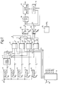
- Figure 1 shows a modulator for digital signals, using quadrature amplitude modulation (QAM). It is switchable between a number of different data rates each of which is a multiple of some base rate; a base rate of 2400 bit/s is assumed, though the actual choice does not affect the principles involved. Thus, at any time, data is received at an input 1 at a rate of i.2400 bits/second. Typically the values of i at which the modulator is capable of operating are in the range 1 ⁇ i ⁇ 10 though in principle there is no limit to i.
- QAM quadrature amplitude modulation
- a common method of improving the error performance of such digital signals is to make available a larger choice of QAM symbols than is necessary to carry the data. For example if a 2 m+1 -point QAM constellation is available for transmitting m data bits per symbol then the latter can be coded using an error-correcting code (e.g. by means of a convolutional coder) and a decoder can make use of the fact that not all symbol sequences are allowable by recognising non-allowable sequences as indicative of transmission errors and hence correcting at least some of the errors by finding the nearest allowable sequence.
- a coding overhead i.e. redundancy
- the symbols can be assembled into groups of c symbols which together carry one coding bit (or, more generally, j coding bits), so that the number of possible symbol sequences in a period cT is 2 cm+j .
- groups are commonly referred to as multidimensional symbols but, for clarity, in this description the term "symbol" is used to refer to a single QAM symbol.
- each QAM symbol carries 2 signal dimensions
- PAM (baseband) systems can be included if we reinterpret each 'QAM symbol' as a pair of PAM symbols at amplitudes equal to the two 'QAM symbol' co-ordinates.
- this is not an integer so we consider intervals AT containing A symbols, where A is the lowest common multiple of a and c.
- the code rate (ratio of the number of data bits to total bits is ibA/a(ibA/a + jA/c).
- the task of the coder is to:
- the input bits are of equal status it does not matter which 21 bits are chosen - hence the description of the manner in which the input bits are distributed is merely a convenient example. However, these 21 bits must be used correctly in the QAM process to ensure that a coding gain is achieved.
- the 120 bits of data during the period AT are used to generate 13 "small" symbols and 15 large ones, as follows: 3 bits convolutional coding 4 bits 1st, 2nd & 3rd groups of 4 symbols (small) 4 bits to choose signal sets 4 bits 8 bits uncoded 8 bits 3x16 bits 3 bits convolutional coding 4 bits 4th group 1 small symbol @ 4 bits 3 large symbols @ 5 bits 4 bits to choose signal sets 4 bits 11 bits uncoded 11 bits 3 bits convolutional coding 4 bits 5th-7th groups 4 large symbols @ 5 bits 4 bits to choose signal sets 4 bits 12 bits uncoded 12 bits 3x20 bits
- data bits received at an input 1 are distributed to selected ones of five serial-in/parallel-out registers 4-8, so as to assemble data bits for constructing a single symbol group.
- Each has a length of 7 bits.
- the registers are clocked by i.2400Hz clock pulses ⁇ 1 ... ⁇ 5 from a pulse generator 9 whose operation depends on the currently selected data rate.
- This generator operates in regular cycles of duration AT, within which it runs through seven sub-cycles of different lengths.
- the first to third sub-cycles each consist (as shown in Figure 2) of, in succession, 7 pulses ⁇ 1 and 2 pulses each ⁇ 2 ... ⁇ 5.
- the fourth sub-cycle has 7 pulses ⁇ 1 , 2 pulses ⁇ 2 , and 3 pulses each ⁇ 2 - ⁇ 5 .
- the fifth to seventh sub-cycles have 7 pulses ⁇ 1 and groups of 3 pulses ⁇ 2 - ⁇ 5 in each case.
- the total number of pulses is, of course, 120.
- each sub-cycle corresponds to a group of four QAM symbols and contains three ⁇ 1 pulses to select 3 data bits for the convolutional coder, (giving 4 bits) plus four ⁇ 1 pulses to give a total of 8 bits selecting the signal sets.
- the pulses ⁇ 3 - ⁇ 5 are k-2 or k-1 in number, or a mixture of k-2 and k-1 according to whether the symbols in that group are to be chosen from the 2 k or 2 k+1 constellations or a combination thereof.
- the pulse generator 9 has an input 10 to indicate the data rate, and thereby select the required pulse sequences.
- the total number of pulses in a complete cycle is 24 x i.
- the 7 bits output from the register 4 feeds a convolutional coder 2 which produces an output of eight coded bits. These bits are derived from the seven input bits and one other. This other bit is determined by the state of the convolutional coder and three of the input bits. All eight bits are here referred to as "coded bits", irrespective of the operation of the convolutional coder 2, to distinguish them from the uncoded bits in registers 5 to 8.
- the eight coded bits from the convolutional coder are appended in pairs to the k-2 bit or k-1 bit word stored in a respective one of the registers 5 to 8; the composite word is transferred to respective holding registers 11 to 14 by pulses ⁇ ' 2 ... ⁇ ' 5 occurring after pulses ⁇ 2 , ⁇ 3 etc.. Those pulses also reset the registers 5 to 8 to ensure that whenever fewer than 7 bits are clocked into a register, the remaining (rightmost) bits are always zero.
- the contents of the holding registers are selected in turn by a multiplexer 15 controlled by a symbol clock 16 producing regular pulses ⁇ s . These are not in general synchronous with the data clock; a cycle AT contains 24i clock pules and 28 symbol pulses.
- the 9 bit words serve to control a QAM modulator 17.
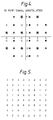
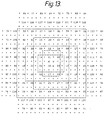
- Suitable 16 and 32 point constellations for use at 12000 bit/s are shown in Figures 3 and 4.
- the relative mapping of the 4 and 5 bit words from the multiplexer 15 is determined by a pair of read-only memories 18, 19 each of which receives the word as the memory address and produces an output I, Q indicating to the modulator 17 the phase and quadrature components of the required point.
- the pair of coded bits must select one of the four subsets of the 16-point constellation distinguished by different shading in Figure 3.
- the assignment of the four combinations of the remaining two bits is arbitrary.
- the sixteen point constellation is contained in the 32-point constellation, then if the fifth bit is employed to select between the outer 16 or inner 16 points, then the same read-only memories can be used for both constellations; i.e. the modulator does not need to know whether, if the first bit is zero, this is because it is to transmit a point from the smaller constellation or because it is to transmit an inner point of the larger.
- the memories will need to be supplied with an additional three bits to indicate the constellation and mapping in use and enable switching to a different 'table' within the memory.
- the pulse generator 9 is shown as supplying four such words (simultaneously) during each sub-cycle which are loaded into registers 11' etc. alongside the registers 11-14 and passing via a multiplexer 15'.
- the embodiment described with reference to Figure 1 is arranged to accommodate a range of symbol rates by switching between a larger and a smaller signal point constellation each having a number of points equal to a power of two.
- constellations having other numbers of points with a resulting improvement in power.
- each group of A symbols consists of A-d symbols chosen from the smaller constellation and d chosen from the larger one.
- the constellations have respectively 2 m points and 2 m+1/h points, where h is an integer power of two and m is either an integer or an integer divided by h.
- a second information bit selects which symbol of the pair it is to be.
- the two symbols are chosen from the outer 2 m-1 and inner 2 m points and carry m-1 and m bits respectively; again the total rate per pair is 2m + 1 bits.
- m is non-integer
- m + 1/2 is an integer.
- the d symbols from the larger constellation carry m + 1/2 bits each.
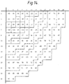
- the constellations may be chosen from Figure 14.
- the solid lines denote the boundaries of 2 k point constellations whilst the shaded/unshaded boundaries show the boundaries of 2 k+1/2 - point constellations.
- the sequence [(3,3) (3,3), (3,3), (3,3)] has an average power of 18. If, every time this sequence would have occurred, the sequence [(5,1), (1,1) (1,1) (1,1)] - the mean power of which is 8 - is sent instead then the overall mean power is slightly reduced. By making a number of such substitutions, it is possible to transmit 16 bits with four signals from Figure 4 with an average power of 9.18. Thus the constellation could be expanded to have a minimum distance between points of 2.09 and still have an average transmitted power of 10. The resulting increase in noise immunity (the shaping gain) is 0.37dB.
- H T [1 +D 2 , 1 +D+D 2 ] ; it has two outputs E 1 , E 0 and one output DR5 and is shown in the figure as a decoder circuit 101.
- the important property of G and H is that if the output of G is fed into the input of H then the output from H is zero.
- the state of the coder 100 i.e. the contents of its delay stages at any time
- s s 1 s 0 .
- s 1 refers to the contents of the leftmost stage in the figure.
- the outputs of the two convolutional coders are combined componentwise by exclusive OR circuits 103, 104 and fed to the input of the decoder circuit 101.
- e 1 cp 1 ⁇ cd 1
- e 0 cp 0 ⁇ cd 0 . Because of the linearity of these circuits the output dr5 of the decoder circuit 101 is always equal to the input d5 of the coder 102, irrespective of the value of bp.
- the signal e is used to select one of the four regions at a transmitter and the decoder circuit 101 is located at a receiver where it can extract from the signals e, recovered from the received symbols, the first (received) data bit dr5 which (in the absence of transmission errors) will be the same as the fifth (transmitted) data bit d5 supplied to the convolutional coder 102.
- the remaining task is to determine the sequence of bits b6 to be supplied to the convolutional coder 100.
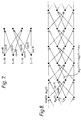
- Figure 7 shows the basic trellis diagram for the coder circuit 100. This shows the ways in which the circuit may proceed from a state s(t) at time t, shown on the left, to a state s(t + T) shown on the right.
- the output cp is shown in each case.
- Selection of the sequence of bp amounts to a selection of a particular path of successive stages of the trellis, namely the one resulting in the lowest power: a longer trellis diagram is shown in Figure 8.
- a longer trellis diagram is shown in Figure 8.
- this decoding takes place over a finite window.
- the window extends from time to time t to time t + 3T (although in practice the window would be larger than this), and the state of the coder at time t has already been determined.
- the state at time t + 3T having smallest p cd (t + 3T) can be identified; the path at time t corresponding to this path is then known, and hence the corresponding cp.
- This, with cd determines the required region and a symbol can be transmitted.
- the state at time t + T is also now fixed and the window can now be shifted one place (i.e. T) to the right and the process repeated.
- This procedure as described, is not optimum in terms of computational complexity (as will be seen below) but serves to illustrate the principle.
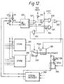
- Figure 9 shows a practical embodiment employing trellis shaping, which receives the signals output from the selector 15 of Figure 1.
- Groups of 6 bits d 5 ??d 0 are received once every symbol period T, from the selector 15, do being a coded bit from the convolutional coder 11 and the remainder being uncoded bits.
- One bit ts from the selector 15' indicates if 1 that there are six data bits and if 0 that there are five (in which case d 5 is to be ignored).
- the most significant valid data bit d 5 or d 4 is selected by a selector 205 controlled by the bit ts and is supplied to a convolutional coder 202 identical to the coder 102 of Figure 6 to produce two coded bits cd 0 , cd 1 which are combined in exclusive OR circuits 203, 204 with trial bits cpt 0 , cpt 1 from a Viterbi decoder 206 to produce a trial region number et 0 , et 1 .
- a store 207 contains a look-up table with 64 entries each representing the power of one of the points of the constellation of Figure 5. It is accessible by means of a 6 bit address, namely et 1 , et 0 from the exclusive OR gates 204, 203 representing the region and databits d 3 ....d 0 identifying the point allocated to it within that region.
- a store 208 has 128 entries representing the powers of the points of Figure 10. There the 7 address inputs are et 1 , et 0 and data bits d 4 ....d 0 .
- the output of one or other store is chosen by a selector 209 controlled by ts.
- the use of a look-up table is preferred in terms of speed and implementation. If however the labeling of the points is systematic, then the powers could be calculated, in which case the store 207 (and 208) would be replaced by a calculation unit in which was stored a sequence of program instructions defining the point mapping.
- the Viterbi decoder 206 supplies to the exclusive OR gates four successive values cp, and thus receives from the selector 209 four power values which indicate the powers of the four points (one in each region of the relevant constellation) which correspond to those values of cp, taking into account the values of d 0 ....d 5 , cd 1 , cd 0 and ts.
- the operation of the Viterbi decoder is the same as for a Viterbi decoder decoding data coded using a convolutional code, except that it receives the path metrics (i.e. the powers) instead of having to compute them by forming the distances between input data and the data associated with the paths.
- the trellis diagram of Figure 7 is inherent in the operation of the Viterbi decoder which now has sufficient information to decide on regions.
- the mode of operation described earlier for illustrative purposes (where metrics were added over the trellis afresh for each window position) is not the usual one: though it works, it is less computationally onerous to simply update the result from the previous window position.
- the problem with this is that it is possible thereby to choose a path within the current window which is inconsistent with earlier decisions (now outside the window) about the path. This can have serious consequences and is therefore necessary to ensure that the survivor path chosen at the end of the window is in fact a path which started at the (now fixed) state at the beginning of the window. This can be done by eliminating, before the next update, any paths that do not converge with the chosen survivor path within the decoding window.
- a typical window length would be in the range 16 to 30. Assuming a window length of 20, this means that there is a delay of 21T between receipt of the data and the Viterbi decoder 206 producing as an output the bits cp 0 , cp 1 for that symbol. Bits d 0 - d 4 and cd 1 , cd 0 are thus delayed by 21T in a delay unit 210.
- the delayed convolutionally coded bits cd 1 , cd 0 are combined with the bits cp 1 , cp 0 from the Viterbi decoder in exclusive OR gates 203', 204' to produce region bits e 1, e 0 .
- the minimum number of regions is three rather than four envisaged by Figure 9. If it were desired to operate the arrangement of Figure 9 with only three regions - e.g. avoiding transmission of points in region 3 of Figures 5 and 10 - then this can readily be accomplished by setting the power levels stored in the tables 207, 208 for the points of region 3 to a very large number, thereby ensuring that the Viterbi decoder 206 never chooses a trellis path resulting in transmission of a signal corresponding to a point in the fourth region. Should it be desired to employ shaping in the case discussed earlier where a constellation having a number of points which is not a power of two is in use, then this may be done in similar fashion.
- a 48-bit constellation is required.
- shaping we define a constellation having three (or more) regions of 24 bits each, each region having 16 "inner” points and 8 "outer” points. Coding of 41 ⁇ 2 bits onto a region can be performed (without at this stage choosing which region is to be used) as before by taking a pair of symbols and processing them jointly in the manner described earlier. This can be done whether or not the two symbols are carrying the same number of bits, as long as they are both carrying an extra half-bit. Once this is done, then one point in each region has been identified and the remaining 1 bit per symbol is used in the shaping process, exactly as described with reference to Figure 9, to choose the regions.
- trellis shaping is restricted to regions 0, 1 and 2, then synchronisation can readily be provided for by allowing the synchronising symbol to use region 3, the region of highest average power.
- One possible method proceeds as follows. Trellis shaping operates without modification. When a point in region 1 or 2 is chosen for the synchronisation symbol, this is transmitted as before. If however a point in region 0 is chosen, then a symbol from region 3 is transmitted instead (in principle regions 1 or 2 could be selected for this substitution but region 0 is preferred since it is statistically likely to be chosen more often).
- Use of a synchronising symbol may be combined with the transmission of a low-speed side channel, the conversion from region 0 to region 3 then being made dependent on a side-channel data bit. This may necessitate a shorter block (a smaller multiple of AT) in order to ensure enough synchronisation (region 3) conditions and to give a required side channel data rate.
- the available side channel data rate will depend somewhat on the data rate in the main channel.
- another symbol i.e. other than the one used for synchronisation
- a substitution of a region 3 symbol can take place, or not, depending on the value of a bit to be transmitted. If region 0 has not been chosen then transmission of the side channel bit is delayed to the next symbol in the block (or to the next designated symbol) for which region 0 has been selected.
- Confusion between synchronisation symbols and "side-channel" symbols may be avoided either by designating for the side channel a symbol chosen from the smaller constellation or by ensuring that a decoder distinguish between the two on the basis that a synchronisation symbol never occupies region 0 whilst a "side-channel” symbol sometimes does.
- a slightly different version of the synchronisation arrangements operates as follows.
- This modified version also involves the "falsification" of the power figures to achieve a desired result, but now the nature of the falsification is time-variant, being, for the symbols designated for synchronisation, different from that for other symbols, In the latter case, the power signal is set to a large number for region 3 and inhibits transmission of points in that region; for the synchronisation symbol however, the correct figures are supplied for region 3 thereby permitting transmissions of a symbol from outer region for this symbol.
- an and-gate 305 is enabled and causes a changeover switch 306 to bring multiplier 306a into circuit to multiply the power signal by a factor equal to the ratio of the mean region 3 power to the mean region 2 power.
- a secondary channel is also to be carried on this symbol then this can be accommodated by using the secondary channel bit to invert (using an exclusive-or gate 309) the output of the and-gate 307 so that the symbol choice is forced to regions 0 and 1 instead of 2 and 3.
- An inverter 310 inverts the secondary data (assuming that the idle state of the latter is logic 1) so that synchronisation is unaffected when the second channel is idle.
- this effect may be enhanced by artificially increasing the power signals (for all three regions) supplied in respect of the adjacent points. Typically this increase might be say x 1.5 for the immediately adjacent symbol and x 1.25 for the next nearest symbol, though in practice the factors would be chosen to suit the tap weights of the filter actually used. This could be achieved by the use of arrangements similar to the switch 306 and multiplier 306a.
- the embodiment described in Figure 9 employed the two constellations shown in Figures 5 and 10. These are 'nested' in the sense that the signal points in Figure 5 are all present in the constellation of Figure 10. It is not essential that the two constellations be related in this way but it is convenient; a small economy of storage in the look-up tables in Figures 1 and 9 is possible if the addressing is arranged so that a single location is used to store the co-ordinates (or power) of a point common to both constellations but the greater advantage is that the front end of a receiver for receiving the transmitted signals has to deal with effectively only one constellation rather than two.
- the mapping of the uncoded bits to the subset of a region is arbitrary: however, the relationship between the mapping in one region to that in another region is of crucial significance to the effectiveness of the shaping process.
- the Viterbi decoder has a choice of four values of cpt and thus a choice among four signal points, one in each of the four regions. It is obvious that, if the mapping is such that, for all values of the input, these four candidate points all have the same power, then no improvement in average power will be obtained by making any particular choice. More generally, it is apparent that some mapping will provide more scope than others for such improvements.
- the objective may be thought of, qualitatively, as offering the Viterbi decoder a wide choice of different powers over the four candidate points.
- the region number is obtained by an exclusive-OR (203', 204') with cd determined by the data but this still results in a 00/11 choice or a 01/10 choice i.e. the convolutional code G implies a pairing of the regions (the actual pairing depending on the code chosen). This property probably holds true for all linear convolutional codes, but not always in the case of a non-linear code.
- the labelling in region 3 (the "other choice" from region 0) follows the reverse sequence from region 0 - viz. descending order of power; thus one has a choice between a point in region 0 having a low power (for that region) and a point in region 3 having a high power (for that region); or vice versa.
- regions 1 and 2 relative to one another.
- the objective of this aspect of the invention is to apply a single labeling system to a set of nested constellations.
- Region 0 of the new constellation (R0') is obtained by combining regions 0 and 1 of the first; and new region (R1') from old regions 2 and 3.
- R0' the points from R0 have a leading 0 added to the label, and those from R1 a leading 1.
- the leading bits for the points of R2 and R3 are 1 and 0 respectively, in order to preserve the "ascending/descending" property discussed above for the new regions.
- a constellation has 16M points. If each region is represented by M points (in one subset) the 4M points are ordered as follows:
- each region is now represented by 2M points.
- R0 and R1 combine to form a region as do R2 and R3.
- the ordering of the points in the first two regions can be exactly the same as above. That is points 0 to 2M-1 come from R0 and R1 and points 2M to 4M-1 of R1' come from R2 and R3. These are the two lowest power regions in the new constellation. Let R2' and R3' be the other two regions with the power of R2' less than the power of R3'.
- the points in R3' are labelled 4M to 6M-1 and are in an order that follows the reverse order of the points 0 to 2M-1. As the power of the points 0 to 2M-1 ascends so the power of the points 4M to 6M-1 descends.
- the points of regions R3' are labelled 6M to 8M-1 and their power ascends as the power of the points 0 to 2M-1 ascends.
- the constellation (or two constellations) used at each rate may be selected from Figure 13.
- the point labelling used enables a good shaping gain at all rates. This is a direct improvement over designing and labeling a new constellation for each data rate.
- the mapping shown in Figure 14 may be used. This shows the point labelling (in hexadecimal) for the lower right quadrant of the phase diagram, and is closer to the (ideal) nesting of concentric circles where the points of each successive region all have higher powers than the points of all previous regions.
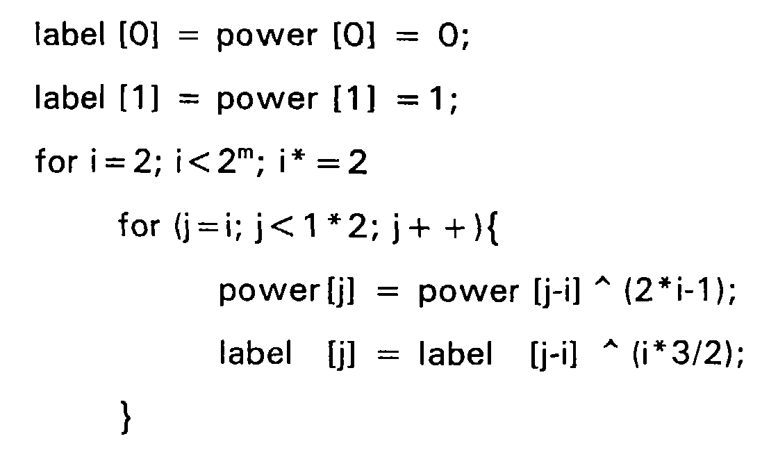
- the labelling shown is obtained by the algorithm below (written in 'C') (for points of equal power, the tie-break used was to take the points having the smallest modulus of the y-coordinate first).
- the indices of label [] are the numbers of the points when ordered in ascending order of power, so that the label for the lowest power point is label [0] and that for the second lowest power point is label [1] and so on. Where trellis shaping is used, this labeling gives comparable shaping gains to the labeling of Figure 13.
Abstract
Description
Then for i = 1, 2, 3, 4, 5, 6, 7, 8, 9, 10
- We have
- B = 31, 55, 79, 103, 127, 151, 175, 199, 223, 247
k = 1, 1, 2, 3, 4, 5, 6, 7, 7, 8
d = 3, 27, 23, 19, 15, 11, 7, 3, 27, 23
| 0000 | 0022 | 0202 | 0220 |
| 1111 | 1133 | 1313 | 1331 |
| 2222 | 2200 | 2020 | 2002 |
| 3333 | 3311 | 3131 | 3113 |
| 3 bits | convolutional coding | 4 bits | 1st, 2nd & 3rd groups of 4 symbols (small) |
| 4 bits | to choose signal sets | 4 bits | |
| 8 bits | uncoded | 8 bits | |
| 3x16 bits | |||
| 3 bits | convolutional coding | 4 bits | 4th group 1 small symbol @ 4 bits 3 large symbols @ 5 bits |
| 4 bits | to choose signal sets | 4 bits | |
| 11 bits | uncoded | 11 bits | |
| 3 bits | convolutional coding | 4 bits | 5th-7th groups 4 large symbols @ 5 bits |
| 4 bits | to choose signal sets | 4 bits | |
| 12 bits | uncoded | 12 bits | |
| 3x20 bits |
- the points 0 to M-1 are the points of R0;
- the points M to 2M-1 are the points of R1 in reverse order of power from those of R0;
- the points 2M to 3M- 1 are the points of R3 in reverse order of power from those of R0; and
- the points 3M to 4M-1 are the points of R2 in the same order of power as those of R0.
RO = (-1,-1); R1 = (-1,3); R2 = (3,-1); R3 = (3,3).
0 (-1,-1) 1 (-1,3) 2 (3,3) 3 (3,-1).
0 (-1,-1) 2 (3,3) 4 (-5,3) 6 (-5,-1)
1 (-1,3) 3 (3,-1) 5 (3,-5) 7 (-1,-5)
Claims (9)
- A method of transmitting data using quadrature amplitude modulation, whereinthe number of transmitted bits per symbol is a rational non-integer greater than unity which when expressed as a ratio B/A of two integers having no common factor the denominator A is not a power of two, and whereineach group of B bits is transmitted by means of A - d symbols, where d is an integer less than A and greater than or equal to 1, each chosen from a first signal point constellation and d symbols each chosen from a second, larger, signal point constellation.
- A method according to Claim 1 whereinone signal constellation has a number of signal points equal to a power of two and the other signal constellation consists of a first plurality of points a power of two in number and a second plurality of points, in number half as many as the first plurality and having a higher average power than the first plurality, and whereinthe signal points chosen from the said other constellation are coded in pairs such that each pair contains at most one symbol from the second plurality of points.
- A method of transmitting data using quadrature amplitude modulation, comprisingassembling groups of q bits,coding one or more of the bits of each group by means of a convolutional or block code to produce an augmented group having at least q + 1 bits, andselecting for each group a symbol for transmission from a signal point constellation having more than 2q points using a variable mapping, the mappings being controlled bygenerating for each augmented group power signals representing the signal power corresponding to each of a plurality of alternative mappings of the group, and decoding the power signals by means of a Viterbi decoder to determine a mapping for that group so as to substantially minimise the time averaged power of the transmitted symbols,in which the constellation comprises a plurality of subgroups of points,in which the transmission has a framing structure,
and in whicha first variable mapping is employed for a symbol at a predetermined position within each frame of the framing structureand a second variable mapping is employed for the remaining symbols,the first variable mapping permitting selection of a symbol from a subgroup having a larger mean power than the remaining subgroupsand the second mapping not permitting selection of a symbol from that subgroup. - A method according to Claim 3 in which the constellation has four, namely first, second, third and fourth such subgroups having progressively larger mean powers, and in which the first variable mapping does not permit selection of a symbol from the first and second subgroups.
- A method according to Claim 4 in which switching between the two variable mappings is achieved by supplying, in respect of candidate points belonging to the fourth subgroup, to the Viterbi decoder,(a) for the symbol at the predetermined position, power signals representing the power of those points and(b)for other symbols, power signals having a high value such as to suppress selection of those candidate points.
- A method according to Claim 5 including supplying to the Viterbi decoder in respect of candidate points belonging to the first and second subgroups, (a) for the symbol at the predetermined position, power signals having a high value such as to suppress selection of those candidate points and
(b) for the other symbols, power signals representing the power of those points. - A method according to Claim 6 including supplying to the Viterbi decoder in respect of a candidate point belonging to the third subgroup,(a) for the symbol at the predetermined position, power signals representing in each case a power larger than the actual power such that the mean power thereby represented for all the points in the subgroup is substantially equal to the mean power of the points in the fourth subgroup; and(b) for the other symbols, power signals representing the power of those points.
- A method of transmitting data using quadrature amplitude modulation, comprisingassembling groups of q bits,coding one or more of the bits of each group by means of a convolutional or block code to produce an augmented group having at least q + 1 bits, andselecting for each group a symbol for transmission from a signal point constellation having more than 2q points using a variable mapping, the mappings being controlled bygenerating for each augmented group power signals representing the signal power corresponding to each of plurality of alternative mappings of the group, anddecoding the power signals by means of a Viterbi decoder to determine a mapping for that group so as to substantially minimise the time averaged power of the transmitted symbols,in which the constellation comprises a plurality of subgroups of points,in which the transmission has a framing structure,in which the constellation has additional signal points forming an additional subgroup thereof not included in the said mapping, andin which, at a predetermined position within each frame of the framing structure, whenever one predetermined subgroup is selected for that position a signal from the additional subgroup is transmitted in lieu thereof.
- An apparatus for transmitting data using quadrature amplitude modulation, comprising:to select a first variable mapping to be employed for a symbol, chosen from a constellation comprising a plurality of subgroups of points, at a predetermined position within each frame of the framing structure and a second variable mapping to be employed for other symbols chosen from the said constellation, the first variable mapping permitting selection of a symbol from a subgroup having a larger mean power than the remaining subgroups and the second mapping not permitting selection of a symbol from that subgroup, and(a) means (4-15) for assembling successive groups of q bits;(b) means (202) for coding one or more bits of each group by means of a convolutional or block code to produce an augmented group having at least q + 1 bits;(c) means (203', 204', 218, 219, 217) for selecting for each group a symbol for transmission from a signal point constellation having more than 2q points using a variable mapping;(d) means (207,208) to generate for each augmented group power signals representing the signal power corresponding to each of a plurality of alternative mappings of the group;(e) means for receiving power signals and in dependence on the power signals for a plurality of groups to determine mappings for that group so as to substantially minimise the time averaged power of the groups;(f) switching means (303) operable in response to timing signals determining a framing structure for the transmission
so to control the power signal generating means as to produce power signals corresponding to the selected mappings.
Applications Claiming Priority (7)
| Application Number | Priority Date | Filing Date | Title |
|---|---|---|---|
| GB9106658 | 1991-03-28 | ||
| GB919106658A GB9106658D0 (en) | 1991-03-28 | 1991-03-28 | Data transmission |
| GB9109006 | 1991-04-26 | ||
| GB919109006A GB9109006D0 (en) | 1991-04-26 | 1991-04-26 | Data transmission |
| GB919112316A GB9112316D0 (en) | 1991-06-07 | 1991-06-07 | Data transmission |
| GB9112316 | 1991-06-07 | ||
| EP92907333A EP0577672B1 (en) | 1991-03-28 | 1992-03-27 | Tcm scheme with fractional bit rates, framing signals and constellation shaping |
Related Parent Applications (1)
| Application Number | Title | Priority Date | Filing Date |
|---|---|---|---|
| EP92907333A Division EP0577672B1 (en) | 1991-03-28 | 1992-03-27 | Tcm scheme with fractional bit rates, framing signals and constellation shaping |
Publications (3)
| Publication Number | Publication Date |
|---|---|
| EP0836305A2 true EP0836305A2 (en) | 1998-04-15 |
| EP0836305A3 EP0836305A3 (en) | 1998-08-26 |
| EP0836305B1 EP0836305B1 (en) | 2004-06-23 |
Family
ID=27265575
Family Applications (2)
| Application Number | Title | Priority Date | Filing Date |
|---|---|---|---|
| EP92907333A Expired - Lifetime EP0577672B1 (en) | 1991-03-28 | 1992-03-27 | Tcm scheme with fractional bit rates, framing signals and constellation shaping |
| EP98200056A Expired - Lifetime EP0836305B1 (en) | 1991-03-28 | 1992-03-27 | TCM scheme with fractional bit rates, framing signals and constellation shaping |
Family Applications Before (1)
| Application Number | Title | Priority Date | Filing Date |
|---|---|---|---|
| EP92907333A Expired - Lifetime EP0577672B1 (en) | 1991-03-28 | 1992-03-27 | Tcm scheme with fractional bit rates, framing signals and constellation shaping |
Country Status (8)
| Country | Link |
|---|---|
| US (1) | US5493586A (en) |
| EP (2) | EP0577672B1 (en) |
| JP (1) | JP3253958B2 (en) |
| CA (1) | CA2106844C (en) |
| DE (2) | DE69233373T2 (en) |
| DK (1) | DK0577672T3 (en) |
| HK (1) | HK1013548A1 (en) |
| WO (1) | WO1992017971A1 (en) |
Cited By (6)
| Publication number | Priority date | Publication date | Assignee | Title |
|---|---|---|---|---|
| EP1487115A1 (en) * | 2003-06-13 | 2004-12-15 | Broadcom Corporation | LDPC (low density parity check) coded modulation symbol decoding |
| EP1494359A2 (en) * | 2003-06-13 | 2005-01-05 | Broadcom Corporation | Multi-dimensional space Gray code maps for mulit-dimensional phase modulation as applied to LDPC (low density parity check coded modulation |
| US7185270B2 (en) | 2003-07-29 | 2007-02-27 | Broadcom Corporation | LDPC (low density parity check) coded modulation hybrid decoding |
| US7322005B2 (en) | 2003-06-13 | 2008-01-22 | Broadcom Corporation | LDPC (Low Density Parity Check) coded modulation symbol decoding using non-Gray code maps for improved performance |
| US7383493B2 (en) | 2003-06-13 | 2008-06-03 | Broadcom Corporation | LDPC (Low Density Parity Check) coded modulation hybrid decoding using non-Gray code maps for improved performance |
| US7436902B2 (en) | 2003-06-13 | 2008-10-14 | Broadcom Corporation | Multi-dimensional space Gray code maps for multi-dimensional phase modulation as applied to LDPC (Low Density Parity Check) coded modulation |
Families Citing this family (33)
| Publication number | Priority date | Publication date | Assignee | Title |
|---|---|---|---|---|
| US5185763A (en) * | 1991-04-09 | 1993-02-09 | Racal-Datacom, Inc. | Data bit to constellation symbol mapper |
| IT1259012B (en) * | 1992-07-27 | 1996-03-11 | Alcatel Italia | METHOD AND CIRCUITS FOR REDUCING THE PEAK POWER OF THE FILTERED SIGNAL TRANSMITTED IN A NUMERIC TYPE CONNECTION |
| US5508748A (en) * | 1993-02-08 | 1996-04-16 | Zenith Electronics Corporation | Data level selection for multilevel VSB transmission system |
| US5684834A (en) * | 1993-06-14 | 1997-11-04 | Paradyne Corporation | Simultaneous analog and digital communication using fractional rate encoding |
| US5521942A (en) * | 1993-06-14 | 1996-05-28 | At&T Corp. | Method for increasing the dynamic range of a signal in a simultaneous voice and data system by the use of overlapping signal point regions and trellis coding |
| US5475713A (en) * | 1993-06-14 | 1995-12-12 | At&T Corp. | Shaped signal spaces in a simultaneous voice and data system |
| US5598435A (en) * | 1993-12-23 | 1997-01-28 | British Telecommunications Public Limited Company | Digital modulation using QAM with multiple signal point constellations not equal to a power of two |
| IT1273695B (en) * | 1994-07-28 | 1997-07-09 | Alcatel Italia | METHOD AND CIRCUITS FOR THE TRANSMISSION AND RECEPTION OF NUMERICAL SIGNALS IN WHICH THE PEAK POWER OF THE FILTERED SIGNAL TRANSMITTED IS REDUCED COMPATIBLE WITH CODING TECHNIQUES NOTES |
| US5774500A (en) * | 1995-12-08 | 1998-06-30 | Board Of Trustees, The Leland Stanford Jr., University | Multi-channel trellis shaper |
| US5878098A (en) * | 1996-06-27 | 1999-03-02 | Motorola, Inc. | Method and apparatus for rate determination in a communication system |
| US5953376A (en) * | 1996-09-26 | 1999-09-14 | Lucent Technologies Inc. | Probabilistic trellis coded modulation with PCM-derived constellations |
| US5862179A (en) * | 1997-02-14 | 1999-01-19 | General Datacomm, Inc. | Mapper for high data rate signalling |
| US5822371A (en) * | 1997-02-14 | 1998-10-13 | General Datacomm Inc. | Mapper for high data rate signalling |
| US5862184A (en) * | 1997-02-14 | 1999-01-19 | General Datacomm, Inc. | Mapper for high data rate transmission through channels subject to robbed bit signalling |
| US6549242B1 (en) * | 1997-04-04 | 2003-04-15 | Harris Corporation | Combining adjacent TV channels for transmission by a common antenna |
| DE19748880C1 (en) | 1997-11-06 | 1999-05-12 | Deutsche Telekom Ag | Method and circuit arrangement for improved data transmission |
| US6163570A (en) | 1998-05-11 | 2000-12-19 | Conexant Systems, Inc. | Methods and apparatus for verifying transmit power levels in a signal point limited transmission system |
| GB2339514A (en) * | 1998-07-11 | 2000-01-26 | Motorola Ltd | Cellular communication system with reduced power variation |
| US6732315B2 (en) * | 2000-01-31 | 2004-05-04 | Texas Instruments Incorporated | Home networking over phone lines |
| US7251270B2 (en) * | 2000-06-20 | 2007-07-31 | Paradyne Corporation | Systems and methods for fractional bit rate encoding in a communication system |
| US6651210B1 (en) * | 2000-12-21 | 2003-11-18 | Arraycomm, Inc. | Flexible multi-bit per symbol rate encoding |
| US6574285B2 (en) * | 2001-07-16 | 2003-06-03 | Northrop Grumman Corporation | 128-ary signal constellations suitable for non-linear amplification |
| WO2003019792A1 (en) * | 2001-08-23 | 2003-03-06 | Nortel Networks Limited | System and method performing quadrature amplitude modulation by combining co-sets and strongly coded co-set identifiers |
| US7161991B2 (en) * | 2002-05-10 | 2007-01-09 | The Boeing Company | Multi-dimensional fractional number of bits modulation scheme |
| US7237074B2 (en) * | 2003-06-13 | 2007-06-26 | Sandisk Corporation | Tracking cells for a memory system |
| US7535975B1 (en) * | 2003-11-07 | 2009-05-19 | Wionics Technologies, Inc. | QAM mapping and bit labeling or bit-interleaved coded modulation |
| US20060092050A1 (en) * | 2004-10-05 | 2006-05-04 | Djokovic Igor S | Trellis constellation shaping |
| CN101094031A (en) * | 2006-06-21 | 2007-12-26 | 株式会社Ntt都科摩 | Data transmission method and device thereof |
| KR20100063797A (en) | 2007-09-17 | 2010-06-11 | 레르 리키드 쏘시에떼 아노님 뿌르 레드 에렉스뿔라따시옹 데 프로세데 조르즈 클로드 | Neutral ligand containing precursors and methods for deposition of a metal containing film |
| CN102404072B (en) * | 2010-09-08 | 2013-03-20 | 华为技术有限公司 | Method for sending information bits, device thereof and system thereof |
| KR101612294B1 (en) * | 2011-02-15 | 2016-04-15 | 삼성전자주식회사 | Apparatus and method for decoding in communication system |
| JP6350921B2 (en) * | 2013-04-12 | 2018-07-04 | サン パテント トラスト | Sending method |
| US11736320B2 (en) * | 2022-02-14 | 2023-08-22 | Ultralogic 6G, Llc | Multiplexed amplitude-phase modulation for 5G/6G noise mitigation |
Citations (5)
| Publication number | Priority date | Publication date | Assignee | Title |
|---|---|---|---|---|
| US4941154A (en) * | 1989-05-30 | 1990-07-10 | At&T Bell Laboratories | Trellis coding method and arrangement for fractional bit rates |
| EP0392723A2 (en) * | 1989-04-10 | 1990-10-17 | AT&T Corp. | Data communications apparatus and method |
| EP0406507A1 (en) * | 1989-07-07 | 1991-01-09 | International Business Machines Corporation | Block coding scheme for fractional-bit transmission |
| US5103227A (en) * | 1990-09-26 | 1992-04-07 | At&T Bell Laboratories | Modulus converter for fractional rate encoding |
| US5119403A (en) * | 1991-04-09 | 1992-06-02 | Racal Data Communications Inc. | Superframes |
Family Cites Families (7)
| Publication number | Priority date | Publication date | Assignee | Title |
|---|---|---|---|---|
| US4597090A (en) * | 1983-04-14 | 1986-06-24 | Codex Corporation | Block coded modulation system |
| EP0122305A1 (en) * | 1983-04-15 | 1984-10-24 | General Electric Company | Polyetherimide-polyamide blends |
| US4713817A (en) * | 1985-04-25 | 1987-12-15 | Codex Corporation | Multidimensional, convolutionally coded communication systems |
| JPH0691520B2 (en) * | 1986-03-24 | 1994-11-14 | 日本電気株式会社 | Out-of-frame detection method |
| US5150381A (en) * | 1989-02-16 | 1992-09-22 | Codex Corporation | Trellis shaping for modulation systems |
| AU630417B2 (en) * | 1989-02-16 | 1992-10-29 | Codex Corporation | Trellis shaping for modulation systems |
| US5214672A (en) * | 1990-04-06 | 1993-05-25 | Codex Corporation | Trellis precoding for fractional bits/baud |
-
1992
- 1992-03-27 DE DE69233373T patent/DE69233373T2/en not_active Expired - Lifetime
- 1992-03-27 DE DE69226361T patent/DE69226361T2/en not_active Expired - Fee Related
- 1992-03-27 JP JP50693792A patent/JP3253958B2/en not_active Expired - Fee Related
- 1992-03-27 EP EP92907333A patent/EP0577672B1/en not_active Expired - Lifetime
- 1992-03-27 WO PCT/GB1992/000562 patent/WO1992017971A1/en active IP Right Grant
- 1992-03-27 EP EP98200056A patent/EP0836305B1/en not_active Expired - Lifetime
- 1992-03-27 US US08/122,524 patent/US5493586A/en not_active Expired - Lifetime
- 1992-03-27 DK DK92907333T patent/DK0577672T3/en active
- 1992-03-27 CA CA002106844A patent/CA2106844C/en not_active Expired - Fee Related
-
1998
- 1998-12-22 HK HK98114846A patent/HK1013548A1/en not_active IP Right Cessation
Patent Citations (5)
| Publication number | Priority date | Publication date | Assignee | Title |
|---|---|---|---|---|
| EP0392723A2 (en) * | 1989-04-10 | 1990-10-17 | AT&T Corp. | Data communications apparatus and method |
| US4941154A (en) * | 1989-05-30 | 1990-07-10 | At&T Bell Laboratories | Trellis coding method and arrangement for fractional bit rates |
| EP0406507A1 (en) * | 1989-07-07 | 1991-01-09 | International Business Machines Corporation | Block coding scheme for fractional-bit transmission |
| US5103227A (en) * | 1990-09-26 | 1992-04-07 | At&T Bell Laboratories | Modulus converter for fractional rate encoding |
| US5119403A (en) * | 1991-04-09 | 1992-06-02 | Racal Data Communications Inc. | Superframes |
Non-Patent Citations (2)
| Title |
|---|
| CALDERBANK, OZAROW: "Nonequiprobable signaling on the Gaussian channel" IEEE TRANSACTIONS ON INFORMATION THEORY., vol. 36, no. 4, July 1990, NEW YORK, US, pages 726-740, XP000133768 * |
| FORNEY ET AL.: "Efficient modulation for band-limited channels" IEEE JOURNAL ON SELECTED AREAS IN COMMUNICATIONS., vol. 2, no. 5, September 1984, NEW YORK, US, pages 632-647, XP002058648 * |
Cited By (9)
| Publication number | Priority date | Publication date | Assignee | Title |
|---|---|---|---|---|
| EP1487115A1 (en) * | 2003-06-13 | 2004-12-15 | Broadcom Corporation | LDPC (low density parity check) coded modulation symbol decoding |
| EP1494359A2 (en) * | 2003-06-13 | 2005-01-05 | Broadcom Corporation | Multi-dimensional space Gray code maps for mulit-dimensional phase modulation as applied to LDPC (low density parity check coded modulation |
| EP1523099A1 (en) * | 2003-06-13 | 2005-04-13 | Broadcom Corporation | Multi-dimensional space gray maps for multi-dimensional phase modulation as applied to LDPC (low density parity check) coded modulation |
| EP1494359A3 (en) * | 2003-06-13 | 2005-08-17 | Broadcom Corporation | Multi-dimensional space Gray code maps for mulit-dimensional phase modulation as applied to LDPC (low density parity check coded modulation |
| US7159170B2 (en) | 2003-06-13 | 2007-01-02 | Broadcom Corporation | LDPC (low density parity check) coded modulation symbol decoding |
| US7322005B2 (en) | 2003-06-13 | 2008-01-22 | Broadcom Corporation | LDPC (Low Density Parity Check) coded modulation symbol decoding using non-Gray code maps for improved performance |
| US7383493B2 (en) | 2003-06-13 | 2008-06-03 | Broadcom Corporation | LDPC (Low Density Parity Check) coded modulation hybrid decoding using non-Gray code maps for improved performance |
| US7436902B2 (en) | 2003-06-13 | 2008-10-14 | Broadcom Corporation | Multi-dimensional space Gray code maps for multi-dimensional phase modulation as applied to LDPC (Low Density Parity Check) coded modulation |
| US7185270B2 (en) | 2003-07-29 | 2007-02-27 | Broadcom Corporation | LDPC (low density parity check) coded modulation hybrid decoding |
Also Published As
| Publication number | Publication date |
|---|---|
| HK1013548A1 (en) | 1999-08-27 |
| DE69233373T2 (en) | 2005-06-30 |
| EP0836305A3 (en) | 1998-08-26 |
| DK0577672T3 (en) | 1999-04-26 |
| DE69226361T2 (en) | 1998-12-24 |
| CA2106844C (en) | 1998-12-01 |
| DE69233373D1 (en) | 2004-07-29 |
| WO1992017971A1 (en) | 1992-10-15 |
| JP3253958B2 (en) | 2002-02-04 |
| EP0836305B1 (en) | 2004-06-23 |
| US5493586A (en) | 1996-02-20 |
| DE69226361D1 (en) | 1998-08-27 |
| EP0577672B1 (en) | 1998-07-22 |
| CA2106844A1 (en) | 1992-09-29 |
| EP0577672A1 (en) | 1994-01-12 |
| JPH06506328A (en) | 1994-07-14 |
Similar Documents
| Publication | Publication Date | Title |
|---|---|---|
| EP0836305B1 (en) | TCM scheme with fractional bit rates, framing signals and constellation shaping | |
| Calderbank | Multilevel codes and multistage decoding | |
| CN1158822C (en) | Slice predictor for signal receiver | |
| CA2157958C (en) | Trellis coded modulation employing lower dimensionality convolutional encoder | |
| CA2013158C (en) | Error correction method and apparatus | |
| US6578173B2 (en) | Cyclic trellis-coded modulation | |
| EP0523816B1 (en) | Apparatus for transmitting streams of information bits and methods for estimating the most likely sequence sent | |
| EP0406507B1 (en) | Block coding scheme for fractional-bit transmission | |
| EP0677966B1 (en) | Concatenated coded vestigial sideband modulation for high definition television | |
| US5418798A (en) | Multidimensional trellis-coded communication system | |
| US5651032A (en) | Apparatus and method for trellis decoder | |
| US5448592A (en) | Coded QAM system | |
| JPH04264852A (en) | Device and method of transferring data | |
| US4939555A (en) | Trellis coding arrangement | |
| CN101686345A (en) | Digital broadcast transmitter/receiver having an improved receiving performance and signal processing method thereof | |
| US4807230A (en) | Frame synchronization | |
| US20070011593A1 (en) | Apparatus and method for receiving signal in a communication system | |
| US5054036A (en) | Digital signal coding | |
| AU665316B2 (en) | Device and method for utilizing zero-padding constellation switching with frame mapping | |
| US6889356B1 (en) | Cyclic trellis coded modulation | |
| US4831635A (en) | Trellis codes with spectral nulls | |
| KR100195746B1 (en) | An apparatus for synchronizing in viterbi decoder | |
| Lin et al. | Fully phase transparent multidimensional trellis-coded MPSK | |
| JP2723002B2 (en) | Uncoded level signal judgment circuit | |
| GB2334862A (en) | Mapping symbol points in a quadrature amplitude modulation |
Legal Events
| Date | Code | Title | Description |
|---|---|---|---|
| PUAI | Public reference made under article 153(3) epc to a published international application that has entered the european phase |
Free format text: ORIGINAL CODE: 0009012 |
|
| AC | Divisional application: reference to earlier application |
Ref document number: 577672 Country of ref document: EP |
|
| AK | Designated contracting states |
Kind code of ref document: A2 Designated state(s): DE DK FR GB IT SE |
|
| PUAL | Search report despatched |
Free format text: ORIGINAL CODE: 0009013 |
|
| AK | Designated contracting states |
Kind code of ref document: A3 Designated state(s): DE DK FR GB IT SE |
|
| 17P | Request for examination filed |
Effective date: 19990226 |
|
| 17Q | First examination report despatched |
Effective date: 19990923 |
|
| GRAP | Despatch of communication of intention to grant a patent |
Free format text: ORIGINAL CODE: EPIDOSNIGR1 |
|
| RIN1 | Information on inventor provided before grant (corrected) |
Inventor name: WILLIAMS, RICHARD GUY CARRINGTON Inventor name: BROWNLIE, JOHN DAVID |
|
| GRAS | Grant fee paid |
Free format text: ORIGINAL CODE: EPIDOSNIGR3 |
|
| GRAA | (expected) grant |
Free format text: ORIGINAL CODE: 0009210 |
|
| AC | Divisional application: reference to earlier application |
Ref document number: 0577672 Country of ref document: EP Kind code of ref document: P |
|
| AK | Designated contracting states |
Kind code of ref document: B1 Designated state(s): DE DK FR GB IT SE |
|
| PG25 | Lapsed in a contracting state [announced via postgrant information from national office to epo] |
Ref country code: IT Free format text: LAPSE BECAUSE OF FAILURE TO SUBMIT A TRANSLATION OF THE DESCRIPTION OR TO PAY THE FEE WITHIN THE PRE;WARNING: LAPSES OF ITALIAN PATENTS WITH EFFECTIVE DATE BEFORE 2007 MAY HAVE OCCURRED AT ANY TIME BEFORE 2007. THE CORRECT EFFECTIVE DATE MAY BE DIFFERENT FROM THE ONE RECORDED.SCRIBED TIME-LIMIT Effective date: 20040623 |
|
| REG | Reference to a national code |
Ref country code: GB Ref legal event code: FG4D |
|
| REF | Corresponds to: |
Ref document number: 69233373 Country of ref document: DE Date of ref document: 20040729 Kind code of ref document: P |
|
| PG25 | Lapsed in a contracting state [announced via postgrant information from national office to epo] |
Ref country code: SE Free format text: LAPSE BECAUSE OF FAILURE TO SUBMIT A TRANSLATION OF THE DESCRIPTION OR TO PAY THE FEE WITHIN THE PRESCRIBED TIME-LIMIT Effective date: 20040923 Ref country code: DK Free format text: LAPSE BECAUSE OF FAILURE TO SUBMIT A TRANSLATION OF THE DESCRIPTION OR TO PAY THE FEE WITHIN THE PRESCRIBED TIME-LIMIT Effective date: 20040923 |
|
| ET | Fr: translation filed | ||
| PLBE | No opposition filed within time limit |
Free format text: ORIGINAL CODE: 0009261 |
|
| STAA | Information on the status of an ep patent application or granted ep patent |
Free format text: STATUS: NO OPPOSITION FILED WITHIN TIME LIMIT |
|
| 26N | No opposition filed |
Effective date: 20050324 |
|
| PGFP | Annual fee paid to national office [announced via postgrant information from national office to epo] |
Ref country code: FR Payment date: 20100402 Year of fee payment: 19 |
|
| PGFP | Annual fee paid to national office [announced via postgrant information from national office to epo] |
Ref country code: GB Payment date: 20100322 Year of fee payment: 19 |
|
| PGFP | Annual fee paid to national office [announced via postgrant information from national office to epo] |
Ref country code: DE Payment date: 20100419 Year of fee payment: 19 |
|
| GBPC | Gb: european patent ceased through non-payment of renewal fee |
Effective date: 20110327 |
|
| REG | Reference to a national code |
Ref country code: FR Ref legal event code: ST Effective date: 20111130 |
|
| PG25 | Lapsed in a contracting state [announced via postgrant information from national office to epo] |
Ref country code: DE Free format text: LAPSE BECAUSE OF NON-PAYMENT OF DUE FEES Effective date: 20111001 Ref country code: FR Free format text: LAPSE BECAUSE OF NON-PAYMENT OF DUE FEES Effective date: 20110331 |
|
| REG | Reference to a national code |
Ref country code: DE Ref legal event code: R119 Ref document number: 69233373 Country of ref document: DE Effective date: 20111001 |
|
| PG25 | Lapsed in a contracting state [announced via postgrant information from national office to epo] |
Ref country code: GB Free format text: LAPSE BECAUSE OF NON-PAYMENT OF DUE FEES Effective date: 20110327 |