BACKGROUND OF THE INVENTION
Field of the Invention
The invention relates to improvements in data
retrieval.
Description of the Related Art
Various readers and optical scanning systems have
been developed for reading printed indicia such as bar
code symbols appearing on a label or the surface of an
article and providing information concerning the article
such as the price or nature of the article. The bar code
symbol itself is a coded pattern of indicia comprised of,
for example, a series of bars of various widths spaced
apart from one another to form spaces of various widths,
the bars and spaces having different light reflecting
characteristics. The readers electro-optically transform
the graphic indicia into electrical signals which are
decoded into alpha-numeric characters that are intended
to be descriptive of the article or a characteristic
thereof. Such characters typically are represented in
digital form, and utilized as an input to a data
processing system for applications in point of sale
processing, inventory control and the like.
Known scanning systems comprise a light source for
generating a light beam incident on a bar code symbol and
a light receiver for receiving the reflected light and
decoding the information contained in the bar code symbol
accordingly. The readers may comprise a flying spot
scanning system wherein the light beam is scanned rapidly
across a bar code symbol to be read or a fixed field of
view reading system wherein the bar code symbol to be
read is illuminated as a whole and a CCD (Charge Coupled
Device) array is provided for detecting the light
reflected from the bar code symbol.
Known hand-held optical readers are often in the
shape of a gun having a handle portion and a barrel
portion. The reading window through which the light beam
passes is generally located at the end face of the barrel
portion, and the reader is aimed at the indicia to be
read by the operator holding the handle portion. A
trigger is situated in the region of the junction between
the handle portion and the barrel portion for operation
by the user to actuate the optical reader.
In addition there are known portable hand-held
computers for collecting data and down-loading the data
to a central or peripheral device. The down-loaded data
may be raw data or data that has been processed within
the hand-held computer. Data collection can be carried
out by entering information to the hand-held computer via
a keypad, or by incorporating in the computer an optical
reader for example for reading bar code symbols, or
incorporating a reader for reading a magnetic card strip.
For example when information about various products is
required during inventorying, those products may bear bar
code symbols or magnetic strips, or have associated
magnetic strip cards which are read by the hand-held
computer. The data collected can be transferred from the
hand-held computer to a central or peripheral device by
known means such as radio frequency radio links, wired
connections, infra-red communications or other known
transmission arrangements.
Often, more than one data capture system is required
for a given application. The manufacture of a customized
system for a specific application is expensive and
difficult to modify if it is subsequently desired to
incorporate further data capture options than those
originally provided in the customized device.
In addition, traditional electronic mail or message
delivery services provided on conventional operating
environments (for example BSD Unix, SCO Unix) have
employed a simple mail box scheme where each user
receives messages in a specific mail box or directory.
Each machine or host runs its own copy of the mail
delivery service and each user therefore receives
messages on a particular machine as a result of which
each machine is required to provide local storage and
data duplications occur frequently. To mitigate this
problem a proposed solution within computer networks
having a static configuration has been to offer network
file systems providing a unified access mechanism to
storage space across the network regardless of a
particular machine. Because the relevant files are
retained at a single location, the system provides users
a unified access to mail boxes and prevents user data
duplication on individual machines.
With the advent of portable hand-held computer
devices which communicate with a central computer, or
host by wireless communication a problem has arisen.
Generally the device communicates with an access point
which is in direct communication with the host. As the
device is physically moved, it must re-associate with
access points to the host as it moves outside the range
of one access point and into the range of another. The
problem is further exacerbated when the device is moved
from one basic service area to another in which case a
permanent network mail system cannot be guaranteed either
physically or logically.
Currently known electronic mail delivery services
include at most two independent "tasks": mail user agent
and mail transfer agent. Mail user agent provides user
interface to the service and mail transfer agent deals
with the reception and storage of messages in user mail
boxes. The tasks generally operate independently, mail
user agent being unaware of mail transfer agent status
and simply having access to information about mail box
details for each user. As discussed above, although the
scheme is appropriate when mail boxes are permanently
placed or mounted in a file system and accessible by all
machines of a network, when a portable wireless hand-held
system roams the local area and moves from one basic
service area (file system) to another basic service area,
the scheme does not operate reliably.
Typical examples of known mail delivery systems are
discussed in, for example Sunexpert Magazine of April
1994 in an article entitled "Sendmail" by Peter
Collinson. A message is input to mail user agent and
dealt with by mail transfer agent. On large networks the
various tasks are carried out by a mail hub machine to
which all mail on a network is sent for processing. The
system can be enhanced by introducing the possibility of
expanding mailing lists, running mail through programs
and automatic transfer of mail between certain users. A
system becomes progressively more complex as it moves
from local mail to mail on the Internet to mail between
networks.
Further limitations are imposed because of the
limited storage capability of hand-held computers (often
known as personal digital assistants) as a result of
which simple-store-and-forward, multi-user electronic
message systems are generally impractical.
To operate on a wireless network, mobile units (MUs)
must have a domain in order for them to associate with
the access points (APs) in an access point group (APG).
An APG is a group of one or more access points connected
on the same router on the same network. All access
points in the same APG are identified by the same domain.
This allows the access points in one APG to communicate
over the network without conflicting with other APGs on
the same network.
The disadvantage of prior art domain assignment
protocols is that some MUs may be used on multiple APGs,
and possibly on multiple networks. Use of a mobile unit
on multiple APGs would require changing the domain of the
MU to allow it to communicate via the appropriate APG at
the appropriate time. Use of a mobile unit on multiple
networks might also require changing the domain, since
the APGs on the new network might be in a different
domain.
Further, when a TCP/IP stack is used (transmission
control protocol/internet protocol), each network node
must have a unique IP address for that network. The set
of TCP/IP protocols typically encompasses media access,
packet transport, session communications, file transfer,
electronic mail, and terminal emulation. IP addresses
for different networks need not be unique. If multiple
networks are connected and nodes communicate across all
networks, then the nodes require IP addresses that are
unique across the expanded network.
In summary, each access point on a network must have
a unique IP address for that network. Each mobile unit
on a network, despite the domain it is using, must have
a unique IP address for that network. Mobile units can
be used on multiple networks. Use on multiple networks
generally requires changing the IP address of the MU
since the IP address currently in use by the MU might be
in use by another MU on the new network or might not
conform to the IP address conventions used by the new
network.
Consequently, a system is required for assigning
domains and IP addresses to mobile units to cover a
variety of configurations and many different types of
mobile units. Specifically, a system is required to
allow for the assignment of domains and IP addresses to
mobile units in ways that are sufficiently flexible to
support installations where MUs are fixed to specific
APGs on specific networks and where MUs travel among
different APGs, and possibly among different networks,
such as Spectrum One and Spectrum24 (Trademarks of Symbol
Technologies Inc.) networks.
According to another aspect it has previously been
proposed to implement a bar code scanner resident on a
control machine running a COMPONENT OBJECT MODEL (COM)
object. It is desired to increase the scope of such
applications to be compatible with a wide range of models
and in particular to introduce a bar code scanner remote
from the machine and controlled through a wireless
interface.
Pending European patent application 485,996
discloses, inter alia, a system for the replacement of
depleted inventory using a system in which the
replacement inventory items are labelled with bar coded
ultimate-destination information, and packed into a
container for shipment to a receiving/distribution
centre.
It is known in general to make use of a two-dimensional
bar code symbol, on the exterior of a
container, to indicate what is inside: see Material
Handling Engineering, October 1992, article entitled "New
Dense Code Symbology Transports Data File".
The Internet computer network is gaining ever
increasing significance in the world of science,
technology, information and commerce amongst many others.
The Internet will be well known to the skilled reader
but, in brief summary, comprises a network of computers
practically worldwide and accessible from any access
point suitably linked to retrieve information contained
in the Internet. Various sub-networks exist within the
Internet, one of the best known of which is the worldwide
web.
Information is commonly stored on the Internet in
the form of "pages" often comprising a "home page"
relating to a general site and providing guidance and
access to the contents at that site, the contents being
contained in "sub-pages". A site includes a unique
Internet Protocol address or Universe Resource Locator
(URL). The site can thus be accessed from any access
point to the Internet by entering the relevant address
and displaying the site held at that address. The user
accesses the Internet via a client computer, for example
a PC linked to the Internet. The link will typically be
via a modem and telephone line and a service provider or
server acts as intermediary, the client accessing the
Internet via the server. In addition, the server allows
the user to set up an Internet site. It will be
appreciated that the server generally comprises a fixed
station. Such an arrangement can give rise to an
unnecessary level of inflexibility. In particular it is
often time consuming and unnecessarily complex to have to
access the fixed station server to set up or access an
Internet site.
Various developments to Internet related systems
have been disclosed in US patents. For example US
5,550,984 relates to a security system for connecting
computer networks, US 5,544,162 relates to a bridge for
connecting parallel processors to the external
environment, US 5,517,494 relates to a routing protocol
for multicast messages across the Internet, US 5,416,842
relates to message transmission between firewall servers,
US 5,410,754 relates to an interface between a wire line
carrier and a remote host on a Local Area Network (LAN),
US 5,400,335 relates to an Integrated Services Digital
Network (ISDN) - LAN connection terminal, US 5,353,283
relates to packet transmission across a series of modes
in a network, US 5,351,237 relates to a network of LAN's
connected to an ISDN including a plurality of routers/
sub-routers. US 5,309,437 relates to a bridge-type
device for coupling segments of an extended LAN, US
5,289,468 relates to a terminal adapter for connecting a
LAN and a Wide Area Network (WAN) using an Internet
Standard Protocol, US 5,276,789 relates to graphically
displaying computer network topology, US 5,229,988
relates to a system for classifying duplicate source
address replies, US 5,185,860 relates to a system for
determining the nodes connected to a computer network and
US 5,166,931 relates to a system for an inter-network
arranged to simplify the network addressing system. US
5,442,633 relates to a method for routing a data packet
between a mobile host and a destination host via a
wireless link between the mobile host and a base station.
The base station acts as a physical location of the
mobile host and is linked to the network via a LAN subnetwork.
The mechanism of file name translation across a
distributed network are known, for example, from US
5,483,652, incorporated herewith by reference.
A range of products have been developed by Spyglass
Inc. enhancing the Internet connectivity of existing
devices. In particular these products are designed to
connect electronic products to the worldwide web such as
cellular phones, cable T.V. set-top boxes, televisions,
personal digital assistants and pagers, providing the
infrastructure, applications and services to allow these
devices browsing capability across the Internet. One
such product is available under the trade mark REMOTE
MOSAIC which converts browsing into a client service
operation in which lightweight "viewers" are custom-integrated
into devices which connect to a "proxy
browser" on a remote server. The proxy browser handles
applications demanding excessive process or memory
capabilities such as caching and connects the device to
other servers.
In another aspect there are numerous situations in
which an instantaneous image of a scene or object is of
considerable use and importance, for example in insurance
claims documentation where it is vital to document as
accurately and completely as possible the circumstances
against which the insurance claim is made.
Conventionally details are documented either in writing
or by taking photographs using a film camera. This
information is then subsequently entered with all other
information relating to the insurance claim. Such a
system is time consuming and error-prone, in particular
because of the subsequent re-entry of information and
transfer of the physical photograph to the relevant file.
Similar problems arise, for example, in news coverage of
an incident, police or other authorities' incident
reports and so forth.
US 5,583,994 relates to a multimedia information
delivery network system. A wide area transmitter
transmits the multimedia programs which are received by
a plurality of network servers for re-transmission to
downstream network servers or a user. The programs are
cached at the network servers as determined by a
scheduler for efficient delivery of the multimedia
program to each user.
In another aspect, data terminals connected to the
Internet are conventionally required to download applets
in an appropriate agent implementation language from a
host which is a complex and slow process.
There are several different types of bar code
readers. A first type, a wand 8, contains an emitter 10
and a detector 12, and the user manually moves the wand
across the bar code. The detector 12 senses the light
reflected from a spot scanned by the wand 8 across the
bar code 2, and produces an electrical signal
representing the encoded information to processor means
14. Wands have been disclosed, for example in U.S.
Patent Nos. 4,654,482, 4, 907,264 and 4,937,853.
A document of particular relevance is US Patent No.
4,471,218 which discloses a data wand and a data well,
and is incorporated herein by reference. According to
the specification a wand-type data entry terminal is
entirely self-contained and cordless, and includes
reading and storage circuitry. The terminal further
allows down-loading of the interface using an optically
coupled link. Preferably the stored data is output using
a pulsed beam from the reading beam light source. The
output beam is detected by an optical detector and
decoded appropriately.
The discloses of the above mentioned references are
incorporated herein by reference. The general features
of construction and operation of a wand type reader will
be apparent to the skilled reader.
According to another system described in US
Application Serial No. 08/691,263, filed August 2, 1996,
commonly assigned herewith, a hand-held optical reader
terminal is provided having an ergonomic design.
According to that system there is provided, inter alia,
a hand-held optical reader arranged to fit in the hand of
a user and including a reader component and a down-loading
component. The device can include a display
screen and a display screen for displaying control
messages or video images, a keypad for inputting control
or other data and a wireless communication link for down-loading
data read by the reader component to an external
device. The system can further include a plurality of
interchangeable data collection modules connectable to
the main body of the device, each module fulfilling a
different function such as image/video capture, audio
capture and so forth. As a result a simple multi-media
module is provided.
It is desired, however, to arrive at a light weight
hand-held data reader having a yet wider range of
capabilities.
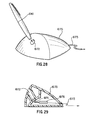
In view of the relative simplicity, availability and
adaptability of information systems including bar code
symbol data storage capability, it is desirable to
develop systems particularly suitable for consumer
applications. A wand-type optical reader which has many
consumer applications is shown in Fig. 21. The
arrangement, generally designated as 680 comprises a pen-shaped
main body 681 having at its writing end an optical
scanner element light emitter and detector 682 for
reading a bar code symbol illustrated schematically as
683. The pen may also include actual writing capability,
for example by having the writing nib adjacent the
optical element 682 or, indeed, having the writing
element and the optical element 682 at opposing ends. It
is desired to increase the range of applications for such
a product. The data processing capabilities of such a
system 680 are limited by its physical size and power
supply potential consequently limiting the range of
applications of the arrangement. In addition various
problems arise in actual operation of such a system, in
particular in regulating the varying speeds at which
consumers scan a given bar code symbol 683.
Conventional portable data terminals comprise a data
display, data input means such as a keyboard and data
storage and processing means. A wide range of
applications are now available on such terminals
including word-processing, spread-sheeting, data base
applications and so forth. Much of the development work
in known portable data terminals is centred on increasing
the data storage and processing capabilities. This has
led to increases in cost and size/weight (and the
corresponding need to subsequently miniaturise
components) together with increased complexity leading to
increased potential for defect or breakdown.
In another aspect, US 5410326 relates to a
programmable remote control device for interacting with
a plurality of remotely controlled devices. The remote
control device is configured to control a variety of
devices and carries pictorial icons representing the
different functions for selection by the user. The
device is further configured to receive and display
advertising messages, and operate various other functions
such as electronic mail and order-out meal delivery. The
system is, however, complex and cumbersome and of limited
adaptability.
US 5,521,370 relates to a hand-held portable data
capture terminal for example for warehousing, which is
mountable in a terminal mount for data communication with
a host computer and/or battery recharging. The
specification is directed to a data interface between the
terminal and the terminal mount comprising abutting
electrical contact pads. The terminal is arranged only
to communicate with the terminal mount when it is docked
therein. The terminal carries a processor and memory
system serving as a communication controller and can be
arranged to act as network controllers when docked. A
difficulty with such a system is that a considerable
processing and memory capability is included in the hand-held
terminal and that data is only downloaded when the
terminal is docked in terminal mount.
US 5,280,621 relates to a control system for a
personal computer. In conventional personal computers a
system control processor provided an interface between
the host processor and peripheral such as a keyboard.
System performance was limited because of the slow
communication rate between the system control processor
and the keyboard, and was further degraded when the
system control processor handled additional control
burdens such as battery power management, external bus
expansion control and so forth. According to US
5,280,621 it is proposed to introduce microcontrollers to
provide communication between respective peripheral
devices and the system control processor, freeing the
system control processor to do other tasks improving the
overall system performance.
The question of power management in portable devices
has been addressed in various manners conventionally. US
5,027,294 relates to monitoring the voltage discharge of
a battery power supply in which the user is issued
warnings at various depletion levels allowing memory
back-up, avoidance of over-depletion and so forth. US
5,504,413 recites a battery charging system including
feedback input allowing minimisation of overhead voltage
levels, and connection of a recharging device to a
peripheral device via a port at the recharger. US
5,487,181 refers to power minimisation providing a main
processor and a lower power processor which allows the
main processor to "sleep" except when required. The
lower power processor carries out various minor functions
allowing the main processor to sleep as far as possible
whilst being awoken as soon as required. US 5,511,205
relates power management in a portable pen-based notebook
computer. The system has a plurality of independently
controllable power planes selectively powerable to ensure
that a particular task is performed with minimum power
consumption. In addition separate CPU's operate
synchronously in relation to one another reducing the
amount of processing time the main CPU is required to
dedicate to the power management function.
SUMMARY OF THE INVENTION
Objects of the Invention
It is an object of the present invention to provide
an arrangement comprising a further improvement over the
prior art.
Features of the Present Invention
In one aspect a reader is provided having a housing
and an information display may be situated on the upper
face of the housing.
A keypad may be provided on the upper face of the
housing, allowing information concerning the operator's
identity, mode of operation and so forth to be entered.
An acoustic modem may be provided for up-loading and/or
down-loading information read by the reader, and/or
an interface connector may be provided for connecting the
reader to a central computer for up-loading or down-loading
information, and/or a radio transmitter may be
provided for transmitting information to a remote
receiver, and/or a radio receiver may be provided for
receiving information from a remote transmitter. In any
case, information may be transferred to a central storage
device allowing space reductions on the reader itself.
The reading arrangement may be a "flying spot"
optical scanner or a "field of view" optical reader.
The reader may be configured for connection with the
Internet. In particular, the reader may be arranged to
read and decode a bar code symbol representing a network
site address, for example a worldwide web URL. Access to
such sites is thus simplified for the user.
According to the invention there is further provided
a portable computer device comprising a main body and at
least one data collection/communications module
connectable to the main body, the main body including an
interface for connection with the module, a processor for
processing information received from the module and a
communication link for exchanging information with a
host. Because of the modular arrangement the device may
be easily adapted to different applications without the
requirement to manufacture costly customized systems or
to modify such systems which would prove expensive and
complex.
The main body may include a visual display, for
example an LCD display. The main body may also comprise
a keypad. The modules may comprise an image capture
module, a laser scanner module and/or a multi-media
module. The modules preferably include digital signal
processing sub-systems which may be of a single design
and programmable as appropriate. The modules may
comprise pre-processors for pre-processing information
prior to transfer to the main body to reduce the burden
on the processor in the main body. The module may be
movably mounted on or relative to the main body, and in
particular to the display on the main body - for example
it may be hinged pivotally or rotatably mounted.
The device may be configured for connection with the
Internet.
According to the invention there is further provided
an electronic mail delivery system comprising a server
portion and a client portion, the client portion
comprising at least one user interface terminal wherein
the client portion is arranged, on receipt of a query by
a specific user, to interrogate the server portion for
messages stored by the user portion addressed to the
specific user. The system is thus suitable for use even
in systems where the client portion is moved physically
between basic service areas.
The client portion and the server portion may
communicate by wireless communication. The client
portion may comprise one or more portable computer
devices.
The client portion may be arranged to receive
messages input by a specific user and to communicate
those messages to the server portion for storage at the
server portion.
The client portion may be arranged to play-back a
message and to determine whether the message is a visual
message or an audio message and to play back the message
accordingly. The system may form part of, or be
configured for connection with the Internet.
Preferably the server portion and the client portion
are provided on a local network arranged to communicate
with other local networks including a server portion and
a client portion via server-server communication, the
mail delivery system being distributed between the local
networks.
According to the invention there is further provided
a method of operation of an electronic mail delivery
system including a server portion and a client portion,
the client portion and server portion being in
communication, in which a user inputs a query to the
client portion, the client portion interrogates the
server portion, the server portion transmits to the
client portion any messages stored in the server portion
specific to the user and the client portion plays back
the messages.
The user may input a message to the client portion
for storage by the server portion, the client portion may
communicate the message to the server portion and the
server portion may store the message.
The client portion may display user options for
selection by the user including the options of storing a
message, retrieving a message, selecting the manner of
display of the options and selecting the manner of
playback. The options may be retrieved from the server
portion by the client portion upon initialization of the
client portion.
According to the invention there is provided a
communication system for a bar code scanner comprising a
control host, a scanning control object working therein
and a remote client associated with the bar code scanner
wherein the scanning control object communicates with the
remote client to control the bar code scanner and the
scanning control object is implemented as an OLE control.
Accordingly there is provided a system capable of
seamless communication between the scanning control and
the remote client.
The host and the scanning object control may
communicate and integrate via interfaces. The scanning
control object may create separate threads of execution
for controlling communication with the remote client.
The separate threads of execution may include send,
receive and synchronize bar code scanner transaction
commands.
The scanning control object may be arranged to
communicate with the remote client over an Internet or
Intranet link and/or by wireless communication.
According to the invention there is further
provided:
According to the present invention there is
provided a data terminal connectable to, and remote from,
the Internet comprising a data input and an internal
server for creating an Internet site representing the
input data and having an Internet Protocol address, the
terminal further comprising a network link cooperating
with the server to provide access to the site to users
elsewhere on the Internet. The system thus provides
substantial benefits as regards speed, efficiency and
accessibility.
The Internet site may be a web site. The data input
may comprise one or more of the group of image recordal
means, sound recording means, or text recordal means.
The network link may be a wireless network link
comprising one of the group of a radio frequency link, an
infrared IRDA standard link or a microwave link over a
private wireless local area network, or a cellular
telephone network.
According to the present invention there is provided
a data terminal connectable to, and remote from, a data
network comprising a data input, means for creating a
user accessible data site representing the input data and
having a site address and a network link arranged to
receive access requests from users elsewhere on the
network addressed to the site, and provide access to the
addressed site.
The network may comprise one of the group of the
Internet, an Intranet or a Local Area Network (LAN), for
example the network comprising the Internet and the site
address comprising an Internet Protocol address. The
site may comprise a Web site.
The data input may comprise one of the group of
image recordal means, sound recordal means or text
recordal means, or even a chemical "sniffer" which
detects the presence of certain chemicals in the air
(e.g. natural gas, or other combustible or hazardous
fumes). The data site creation and access means may
comprise a server internal to the terminal. The network
link may be a wireless link comprising one of the group
of a radio frequency link, an infrared IRDA standard link
or a microwave link.
According to the invention there is provided a
mobile image recording unit connectable to the Internet
via a wireless link comprising image recordal means, a
server for creating an Internet site having an Internet
Protocol address and representing the recorded image and
a wireless link arranged to provide site access to
requests directed to the site address.
The server may create respective sub-pages for
respective recorded images and includes a menu setting
out the sub-pages on a home page at the site address.
According to the invention there is provided an
Internet site creation and access system comprising a
mobile unit including a server arranged to record images
at a given geographical location and create a site
representing the image internal to the terminal, wherein
the mobile unit communicates with the Internet via a
wireless link and users access the site at the mobile
unit via the Internet.
According to the invention there is provided a
method of creating a web site in which a mobile unit
records data relating to its immediate environment, a
server within the mobile unit creates a web site page
representing the data and having an Internet Protocol
address, and Internet users access the web site at the
Internet Protocol address via a wireless link between the
mobile unit and the Internet.
According to the invention there is provided an
image capture and relay system comprising a remote still
image capture device including an encoder for encoding
the captured image as an image data signal and a
transmitter for transmitting the image data signal, the
system further comprising a base station for receiving
the image data signal and providing access to the image
data. As a result, prompt access to the image is allowed
at the base station.
The image capture device may comprise a digital
camera and many further include a bar code reader and/or
a microphone and/or a user data input device and/or
include a printer, preferably arranged to print bar code
symbols or a hard copy version of the captured image.
The image capture device may include a visual
display screen and, advantageously means for altering an
image displayed on the visual display screen.
The invention further relates to in preferred form:
According to the invention there is further provided
a still image capture device comprising a digital camera,
an encoder for encoding the still image as an image data
signal, and a transmitter for transmitting the image data
signal by wireless transmission to a remote base station.
According to the invention there is further provided
a method of capturing and relaying an image comprising
the steps of capturing the image using a remote image
capture device, encoding the captured image as an image
data signal and transmitting the image data signal, the
encoder and transmitter being provided in the remote
image capture device, and receiving the transmitted image
data signal in a base station for distributing the image.
The image captured may relate to a given incident and the
base station may transfer the received image to an
insurance database relating to the incident.
The image captured may relate to the condition of
goods prior to delivery and the received image may be
transferred from the base station to a delivery point for
comparison with the received goods.
The image captured may relate to the condition of
goods to be delivered, the image data signal may be
encoded as a bar code symbol applied to the goods to be
delivered, and the bar code symbol may be decoded at the
point of delivery for comparison of the captured image
with the condition of the goods as received.
According to the invention there is provided a
product information retrieval system for use in
conjunction with the Internet computer network, wherein
product information relating to a selected product is
accessible at an Internet site having an Internet
Protocol site address, wherein the site address is
directly or indirectly represented by a machine-readable
printed indicia, and wherein a hand-held reader is
provided for reading the indicia, storing the site
address represented thereby and down-loading the site
address to a client processor for accessing the product
information at the site address. The product may
comprise a commercial product. The commercial product
may be displayed on printed matter, the machine-readable
indicia being printed in association therewith.
Alternatively the commercial product may be displayed at
a retail outlet and the machine readable indicia may be
printed on the product or product packaging.
The machine-readable printed indicia may comprise a
bar code symbol. The hand-held reader may comprise a bar
code reader, for example a field of view optical reader,
such as a "wand" type optical reader.
The bar code symbol may be printed in one of the
group of formats comprising: UPC, EAN.
The data in the bar code symbol may represent the a
site address, or may simply be a product code which can
be utilized to look up a corresponding site address in a
table, and the site address may be converted into a URL
at the client processor.
According to the invention there is further provided
a "wand" type hand-held optical reader comprising reading
means for reading a printed indicia and data storage
means for storing the data represented by the printed
indicia, arranged to read the printed indicia associated
with a selected product, the reader further having a
down-loading port for down-loading the stored data to a
client processor to retrieve additional data relating to
the product.
In its preferred form the invention further
includes:
The client processor may be linked to the Internet
computer network and the printed indicia may contain an
Internet Protocol site address corresponding to an site
containing additional information relating to the
product. Accordingly the system requires no more than
standard address protocols. The reader may comprise a
bar code reader.
According to the invention there is further provided
a method of retrieving product information wherein the
product information is stored at an Internet computer
network site having an Internet Protocol site address,
and the site address is represented in the form of a
machine-readable printed indicia, comprising the steps of
reading the printed indicia using a hand-held reader,
storing the site address data represented by the indicia
in the storage means in the hand-held reader, down-loading
the site address data from the hand-held reader
to a client processor linked to the Internet and
accessing the Internet site identified by the site
address.
The product may be a commercial product. The
printed indicia may accompany a representation of the
product in printed matter or the product may be displayed
at a retail outlet, the indicia being printed on the
product or its packaging.
According to the invention there is further provided
a product information retrieval system for use in
conjunction with a closed computer network whereby
product information relating to a selected product is
accessible at a site on the network having a site
address, wherein the site address is represented by a
printed indicia, a hand-held reader is provided for
reading the indicia, storing the address data represented
thereby and down-loading the address data to a client
processor on the network for accessing the product
information at the site address. The network may
comprise an LAN. The network may comprise an Intranet
system. The client processor may comprise a network
computer.
According to the invention there is further provided
a product information retrieval system for use in
conjunction with a computer network, whereby product
information relating to a selected product is accessible
at a network site having a site address, wherein the site
address is represented as a printed indicia, a hand-held
reader is provided for reading the indicia, storing the
site address data represented thereby and down-loading
the site address data to a terminal linked to the
network, wherein the terminal comprises data input,
output and display means and outputs to the site address
data to a host computer, and the host computer accesses
the network site for input to and display at the
terminal.
The terminal may comprise a network computer. The
network may comprise the Internet or the network may
comprise an Intranet or the network may comprise an LAN.
According to the invention there is further provided
a method of retrieving product information stored at a
site on a computer network having a site address, wherein
the site address is represented as a printed indicia, the
printed indicia is read by a hand-held reader, the site
address data represented thereby is stored in the hand-held
reader and down-loaded to a terminal linked to the
computer network, the terminal comprising data input,
output and display means, and wherein the site address
data is output from the terminal to a host computer, and
the host computer accesses and inputs to the terminal the
corresponding network site, the terminal displaying the
product information contained at the site address.
The data terminal may comprise only a display means,
data input/output means and data transfer means. The
network may comprise an Intranet network. The network
may comprise a local area network.
According to the invention there is further provided
a method of retrieving data comprising reading
identification information stored as printed indicia
using a stand-alone reader, storing the identification
information in a data storage device provided in the
reader, transferring the stored identification
information from the data storage device to an access
point to a data storage and retrieval system, and
retrieving stored data from the system identified by the
identification information.
In the preferred embodiments the identification
information is used to access an Internet site relating
to the product. In that case, for example, a product in
a magazine carries an accompanying bar code symbol, the
bar code symbol containing the Internet Protocol site
address at which further information concerning the
product can be found. The Internet site can be a web
site. The user stores the site address and down-loads it
to a PC or other access point subsequently, allowing the
Internet site home page or sub-page to be called up and
additional product information accessed. In addition, as
discussed in more detail below, the product can be
purchased, or the user can be directed to related
products.
As a result, information can be stored when the user
does not have access to the data storage and retrieval
system itself. The stored data can act as a reminder or
prompt to the user. A particular application is where
the identification information relates to a product
represented in printed matter in which case further
details can be retrieved subsequently and in many cases
a direct transaction carried out interacting only with
the data storage and retrieval system.
The stand-alone reader may be a hand-held reader.
The printed indicia may comprise a bar code symbol and
the stand-alone reader may comprise a wand-type bar code
reader. The identification information may relate to a
selected product and the retrieved data may comprise
additional information concerning the product. The
access point may comprise an interface to a personal
computer or a dedicated down-loading port. The latter
allows use of the invention even where the user does not
have access to a PC.
The identification information may be transferred
via a touch memory interface. The data storage and
retrieval system may comprise the , the identification
information may comprise a web site address and the
retrieved data may be held at the web site.
Alternatively the data storage and retrieval system may
comprise a closed computer network such as an Intranet or
LAN. In that case the identification information may
comprise an appropriate site or database location address
conforming with the protocol adopted by the Intranet or
LAN. The reader data storage device may store data
relating to the reader user, and the reader user
information may be transferred together with the stored
identification information to the data storage and
retrieval system. This assists in further transactions
such as purchase and allows a customer profile to be
assembled.
According to the one aspect the invention relates to
a data processing system comprising a portable terminal
and a terminal mount wherein the mount includes a
terminal interface and processor capability for
processing data received from the terminal and the
terminal includes a user interface, a mount interface and
processor capability sufficient only to relay user input
to the mount for processing and data from the mount to
the user interface. Thus an ultra thin client is
provided at the terminal, the mount carrying out the
majority of the computing functions.
In another aspect the invention relates to a data
processing system comprising a stand-alone data terminal,
docking means for docking the terminal and a host
network, the terminal including a user input and docking
means interface arranged to relay user input to the mount
and the mount including a terminal interface and a host
interface arranged to relay the user input to the host,
for processing and a method of relaying data between a
portable terminal and a base station comprising the steps
of inputting data to the terminal, relaying the data to
the base station with minimal processing and processing
the data at the base station. Optionally, therefore, the
majority of the processing power can be maintained at the
host, allowing a thin docking means or cradle.
Preferred features further comprise:
According to another aspect the invention provides
a product information retrieval system comprising a
portable terminal arranged to receive data from one or
more data output points in a product access zone in which
the terminal is arranged to display an image of a product
to be accessed in response to data received from the data
output point and a method of retrieving product
information in which a portable terminal is provided in
a product access zone and receives data from one or more
data output points, and in which the terminal displays an
image of a product to be accessed in response to data
received from a data output point, and a portable data
terminal for operation in an operation zone having one or
more physical items located at predetermined positions in
the zone wherein the data terminal comprises a
communications receiver and/or transmitter and a display
arranged to display icon's representative of the physical
item and/or its position in the operation zone. This
icon based system allows a highly user-friendly,
efficient and human-error free file system to be
implemented.
Yet further preferred features comprise:
According to another aspect there is provided a
terminal mount for mounting a portable data terminal, the
mount being adapted for wireless communication with the
data terminal, wherein the mount is arranged to receive
or derive display format information for a terminal to be
mounted thereon and configure data to be displayed at the
terminal according to the display format.
Further preferred features comprise:
According to another aspect there is provided a data
communications system comprising a portable data
communication device and a device mount arranged to
releasably receive the device, in which the device mount
includes a user identification information input and a
device lock arranged to release the device on input of
approved user identification information and a method of
monitoring access to a portable data communication device
wherein the portable data communication device is
releasably received in a device mount, a user inputs user
identification information to the mount, the mount
releases the device if the identification information is
approved and, simultaneously, commences the timer, the
timer is stopped when the terminal is reinserted on the
mount and the identified user is billed for the timed
period between release and reinsertion of the device.
This arrangement is particularly suitable for rental in
a public place such as an airport or retail outlet ("self
shopper").
Further preferred features include:
The invention further relates to a data
communication device including wireless communication
means for communicating with one or more access points to
a local computer network, the device further comprising
cellular telephone means for conventional telephone
communication when the device is out of range of the
access points to local computer network, a goods
transport tracking system comprising a communication
device for a transport vehicle arranged to log receipt
and/or delivery of goods and including means for wireless
communication with a communication network and means for
creating a data file accessible via the communication
network to provide receipt/delivery information, a goods
transport tracking network comprising a physical network
of transfer points comprising transport vehicles and
intermediate stations and a communications network, in
which an interface to the communications network is
provided at each transfer point and in which the passage
of goods is logged at each transfer point allowing
transport information to be accessed at the
communications network, a rechargeable battery pack for
an electrically powered device arranged to be received in
a battery charger for recharging, in which the battery
pack has predetermined recharging requirements and
includes recharging control circuitry for controlling the
recharge operation to meet the predetermined requirements
and a battery recharger for receiving and recharging a
rechargeable battery pack having predetermined recharging
requirements and responsive to recharging control means
on the battery pack to control recharge operation to meet
the predetermined recharging requirements.
Further preferred features include:
The invention further provides a data device
arranged to communicate with a communication network
including an adapter module interface and an adapter
module in which the adapter module carries network
communication capability and an adapter module for a data
device communicating with a communication network in
which the adapter module carries network communication
capability for the device. As a result transparent
network file access is achieved.
Further preferred features include:
BRIEF DESCRIPTION OF THE DRAWINGS
The foregoing objects and advantages of the present
invention may be more readily understood by one skilled
in the art with reference being had to the following
detailed description of several preferred embodiments
thereof, taken in conjunction with the accompanying
drawings wherein like elements are designated by
identical reference numerals throughout several views,
and in which:
Detailed Description of the Preferred Embodiments
Throughout the description of the optical reader the
terms "front", "rear", "upper", "above", "lower" and
"below" are used consistently. Referring, for example,
to Fig. 1 an optical reader has a rear end 4 and a
generally planar front end 5, an upper face 2a and
opposed to that a lower face 2b.
Referring to Fig. 1 in more detail the optical
reader includes a generally bar-shaped elongate housing
indicated generally by the reference numeral 1, having
two generally opposed long broad upper and lower faces
2a, 2b, two generally opposed long, shallow side faces 3,
a rear end 4 and a front end 5.
A reading arrangement is mounted within the housing.
The reading arrangement may be any known conventional
arrangement, for example a "flying spot" optical scanner
or a "field of view" optical reader. Generally the
arrangement will include a light generating source such
as a laser diode, a beam focusing or directing
arrangement and a light receiving device. Where the
reading arrangement is an optical scanner a rapidly
oscillatable scan component, such as a mirror is provided
to scan the light beam across an indicia to be read.
Alternatively, the laser diode itself can be oscillated.
Where the reader is a field of view optical reader a
charge coupled device (CCD) array, or a photodetector
arrangement is provided to detect the reflected light
beam.
In order to actuate the reading arrangement a scan
trigger 9 is provided on the upper surface 2a of the
housing 1. The trigger 9 is activated by depression and
is positioned along the housing 1 such that it is easily
actuable by the operator when the reader is held in the
operator's hand. The trigger mechanism itself may be of
any known arrangement; for example the trigger may be
spring-loaded and have contacts which form a circuit with
contacts within the housing when the trigger is depressed
to actuate the reading arrangement.
A scanning window 10 is positioned on the front face
5 of the reader. Light generated by the reading
arrangement passes through the window 10 and is reflected
and scattered back through the window 10 by a bar code
symbol 11. Accordingly the reader can be easily and
accurately aimed at a bar code symbol 11 to be read.
Also provided on the upper face of the reader are a
keypad 14 and a display 15. The keypad 14 may be used to
initialize the reading arrangement such that
identification information concerning the user is entered
into the system. Alternatively, the keypad 14 may be
used to enter predetermined codes or information
concerning modes of operation of the reader or to carry
out cancellation or manipulation operations on
information provided by the reader. The display 15 may
display information relating to the mode of operation of
the reader, or display check information relating to the
item carrying the bar code symbol being read together
with background information such as the time, date, and
confirmation of the operator's identity. Preferably the
display 15 is a liquid crystal display (LCD).
The reading arrangement can process information
derived from the bar code symbols directly or can send
raw data to an external processing device which can then
process the information accordingly. In addition,
information derived by the reader from bar code symbols
can be transferred to a memory device in order that a
database of information can be built up. For example
where the reader is used at a point of sale, buying
patterns can be stored and analyzed. Alternatively, if
the reader is being used for inventorying purposes then
the inventory information can be stored. The optical
reader can transmit information in a variety of manners.
In the embodiments shown various different transmitting
devices are provided; in practice only one or more of the
devices need be provided depending on the particular use
to which the reader is to be put. For example the
information may be transmitted by an acoustic modem 16.
In that case, information can be stored in a buffer
memory within the reader and then down-loaded by the
acoustic modem 16 at predetermined intervals. The
display 15 could indicate when information was to be
down-loaded. Alteratively an interface connector, for
example an RS41 connector is designated by reference
numeral 6 and provided at the rear of the reader.
Suitable cabling can be inserted into the connector 6 to
down-load information or alternatively to load data into
the reader for example relating to the mode of operation.
Once again, the display 15 could provide an indication of
the functioning of the connector. The cable could be
permanently connected to the reader as the connector 6 is
provided at the rear of the reader and hence would not be
obscured by the user's hand. Alternatively, the
connector 6 could be connected to a cable for loading or
down-loading of information when required and, for
example, when indicated by display 15. In addition, a
radio 17 or other transmitting device can be provided
within the housing 1 to allow real time data
communication. An advantage of that arrangement is that
the operator may use the reader in a "cordless" or
"wireless" configuration allowing increased mobility.
Once again the radio 17 could comprise a transmitter and
a receiver in order that information can be sent to and
from a remote processor. The radio link could be
replaced by an infra-red communication link or other
wireless link of known type. Because the reader is of
ergonomic design, the transfer of information is easily
carried out while the reader is actually in use, if
required.
As a further option the reader may be configured for
connection to a telecommunications network or computer
network, for example the "Internet".
One example of where the reader may be of particular
use is in relation to the worldwide web. When it is
desired to access a web site it is necessary to enter the
address of the site, known as the universal resource
locater (URL). Often those URL's are long and complex,
and are time consuming to enter and check manually.
Furthermore the URL can, despite many checks, still give
rise to error. The problem is exacerbated in the case of
computer illiterate users. The proposed manner of
overcoming this problem is to encode the URL address in
a bar code symbol and read the bar code symbol with the
reader for automatic access to the corresponding web
site, which will be quick and accurate, giving rise
to far less margin for error. The reader may be used to
interface with a terminal for entry of the URL address or
could be used independently.
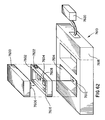
According to another aspect there is shown in Fig.
9 a data collection device comprising an improvement over
known arrangements. The device comprises a portable
hand-held computer for collecting data and down-loading
the raw processed data to a central or peripheral device.
The device, designated generally as 20 comprises a main
body 21 and interchangeable data collection modules 22a,
22b, 22c.
The main body 21 is provided internally with data
processing means (not shown) and also comprises a display
screen 23, for example an LCD display screen capable of
displaying video images, a data collection module
interface 24, an optional input information keypad 25 and
a communication link 26 which may comprise radio
frequency or infra-red transmitting means or an interface
for down-loading information to a central or peripheral
device via a physical cable. It will be appreciated that
the LCD display 23 and input keypad 25 are optional
features. Advantageously, however, they allow the user
to configure operation of the device as a whole quickly
and simply and monitor the operation. The main body is
shown schematically in Fig. 9; in practice it could
assume an ergonomic shape such as that shown in Fig. 1
suitable interfaces etc. being positioned as appropriate,
for example at respective ends of the module.
It will be appreciated that the device may transfer
information to a host via any electronic data transfer
scheme - for example the system could also use cellular-based
telephone channels.
Alternatively the device could be configured for
connection to a telecommunications network or computer
network, for example the "Internet".
The data collection modules are interchangeable with
one another and may be, for example, CCD (Charge Coupled
Device) based image, video and bar code symbol data
capture modules, audio transducers for collecting and
receiving sound information, laser image scanners or
combined multi-media data collection modules.
An image capture module using a CCD could be used
for capturing images of objects for storage or use by a
processor application carried out by the main body or by
a host, such images including for example people,
landscapes, homes and vehicles for reference
applications. In addition the imager could be used for
one dimensional or two dimensional bar code symbols for
decoding data capture. A laser optical reader scanning
module and decoder would be used generally for bar code
data capture and decoding only.
A multi-media module 22 is shown in Fig. 11 and
discussed in more detail with reference to that figure
below. Such a module could contain a circuitry for
image/video capture, audio capture and playback and a
cellular telephony sub-system. Such a module would be of
particular use in tele-conferencing and live video
communications over cellular networks from the portable
unit.
The desired data collection module 22a,b,c is
connected to the main body 21 by the interface 24 on the
main body which mates with an interface 27 on the module.
Any suitable known interface components can be used but
the components should be strong, relatively inflexible,
durable and suitable for frequent disconnection and
reconnection.
The modules are powered by a power supply within the
main body of the portable computing device and may be
partially or totally controlled by software drivers
within the main body. In order to reduce the burden on
the central processing unit of the main body, dedicated
signal processing electronics within the modules can be
arranged to perform up-front data processing as a result
of which a common bus architecture to the main body is
shared by all of the modules. As a result their
interchangeability is enhanced.
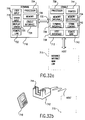
A suitable architecture for an optical media capture
module 28 (for example containing a CCD imager or laser
scanner) is shown in Fig. 10. Each module may contain
only the media capture electronics without any pre-processing
capability or, as discussed above, preferably
contains dedicated or programmable analog components 32
and digital signal processing (DSP) components 33 to ease
the processing load placed on the central processing unit
of the main body 21. The digital signal processing sub-system
32,33 in the module may be of a single electronic
design common to different modules, and which is either
programmed in the factory or customized on purchase or
programmable by the user to perform the functions in
processors if required by the particular media module.
This function programmability is expected to be mainly
through software, since the module processing electronics
are flexible, and these software components may be one-time
or dynamically loaded to the module via the main
body central processing unit. Accordingly the range of
components that require manufacture is decreased,
appropriate dedicated parts of the components being
selectable for a desired use, or a portion of the mode of
operation being borne by software.
In operation, the module 28 collects information via
the CCD imager or laser scanner in analog form which is
transferred either serially or by conversion into a
parallel format. The analog signal is then processed by
the digital signal processing sub-system 32,33 and
forwarded to an interface bus 34 from which the
information is transferred to the main body of the
portable computing device. As mentioned above, the
signal processing electronics preferably perform up-front
data processing such that a common bus architecture to
the portable computing device 21 can be achieved.
Referring now to Fig. 11 the multi-media module 22
includes circuitry for image/video capture, audio capture
and playback and a cellular telephony sub-system.
The module is arranged to receive and transmit video
information independently of the main body of the
portable computing device (although the video information
may also be accessed by the main body of the portable
computing device in order to monitor or review the
information). Accordingly a radio frequency antenna 41
is provided in the module for reception and transmission
of radio frequency information. A radio frequency front
end processor 42 and codec 43 cooperate to perform
digital to radio frequency/radio frequency to digital
format conversions. Video information received via radio
frequency is decompressed by an optional digital signal
processing sub-system 44 for presentation, where
appropriate, to the CPU of the main body 21 of the
portable computing device. A further digital signal
processing sub-system 45 is provided for other purposes
(discussed in more detail below) and preferably performs
partial video processing, the CPU of the personal
computing device completing the process for displaying
the results. The second digital signal processing sub-system
44 may also be required for the interface to the
radio frequency codec 43 of the cellular sub-system; this
depends on the amount of processing required for each
function. Video information transferred to the main body
21 of the portable computing device is displayed on the
LCD display 23. The radio frequency receiving,
transmitting and processing apparatus 41,42,43,44
discussed above can optionally reside in a separate
component such as a PCMCIA or other type plug-in card for
example of the type manufactured by Symbol Technologies,
Inc. Preferably, however, the circuit forms an integral
part of the multi-media module to provide a full wireless
multi-media solution for the hand-held computing system.
As will be appreciated, the wireless link may conform to
any desired cellular standard (for example CDMA, GSM,
AMPS) that is preferably selected to allow the widest
application of the invention.
The multi-media module 22 further includes a
microphone/speaker component 50 which receives and
transfers input analog information to an analog to
digital converter 51,45 comprising an up-front voice-band
converter 51 which transfers information either serially
or in parallel to the digital signal processing sub-system
45. Similarly, information may be transmitted in
the other direction, for example digital information from
the main body of the portable computer device is
converted to an analog audio signal at converter 45,51
and converted to sound by the speaker component 50.
Base-band digital audio data is processed by the digital
signal processing sub-system 45 which can be reprogrammed
as appropriate to perform appropriate audio codec
processing. Voice-band (VB) signals are converted by the
converter 45,51 as discussed above.
Video data is captured by a CCD imager 52 compressed
by a digital signal processing sub-system 53 and
forwarded to the radio frequency codec 43. Once again
the main body of the portable computing device need not
be involved in this data transfer unless the user decides
to monitor the transfer. In that case, a software
controlled process may be initiated whereby the video
data is sent to the CPU of the main body 21 of the
portable computing device for display before compression
as well as to the radio frequency codec 43 for
transmission allowing the captured image to be viewed
while or before transmitting.
The multi-media module 22 is preferably mounted so
as to be rotatable through at least 180° when connected
with the main body of the portable computing device.
This may be achieved by hinging or pivoting or otherwise
arranging a portion of the main body or by similarly
arranging a portion of the module. This positioning
allows capture of the user's image while the user can
simultaneously view the LCD screen display for received
video data or images. The rotation of the image capture
portion of the module permits capture of images of
objects in front of the user while the user is looking at
the screen.
The microphone and speaker combination may be
arranged to face the user in a preferred, standard
configuration of the device as a whole. The microphone
may further be configured to swing or swivel away from
the main body of the portable computer device and from
the user holding the device if the desired audio data to
be captured emanates from another direction.
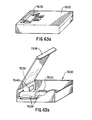
An appropriate arrangement including a pivotable
module head 22 and a swingable microphone boom 30 is
shown in Fig. 12. In the embodiment shown an upper
portion 21a of the main body 21 is hinged to the
remainder of the main body and rotatable around an axis
A as shown by arrow A'. The multi-media module 22 is
connected to the upper portion and the upper portion has
been swivelled such that a CCD image capture device 29
faces the user. The pivotable microphone boom 30 also
extends from the multi-media module 22. It will be
appreciated that a number of pivoting orientating
arrangements can be provided, for example a hinge or
pivot could be provided within the structure of the
module 22, and the module could also be arranged to
rotate through 180° about an axis transverse to axis A.
Similarly, the microphone boom 30 can be pivotally
mounted to the module 22 in any known manner.
Accordingly it will be seen that the invention can
be used to provide modular programmable multi-media
facilities in the hand-held form factor by portable
computing devices such as hand-held terminals or
"portable digital assistants". The invention can be used
for CCD based bar code decoding (in one or two dimensions
at least) by industrial and commercial users, for example
for point of sale processing or inventorying; portable,
cellular video conferences by travelling business users;
and digital photography/image capture for insurance
assessors, sales professionals among many other
applications that will be apparent to those skilled in
the art. It will be appreciated that the portable
modules discussed above may be used in cordless scanning
implementations for example in point of sale
applications. Problems arise where such portable devices
are not tethered in some manner as it is possible that
they will be lost, removed from the store, or otherwise
misappropriated.
To overcome this, it is possible to put surveillance
tags of a known type into the scanner such that if the
scanner is accidently taken by a customer an alarm will
sound at the front of the store as it would if any other
product carrying such a surveillance tag was carried out
of the store.
Alternatively the scanner can have some form of
internal alarm which sounds if the scanner is taken more
than a predetermined distance from the base. Where the
scanner communicates with the base by wireless
communications such as radio communication, the software
protocol managing the radio session could control the
range finder and alarm.
In order to locate portable scanners that have been
misplaced an alarm or "beeper" can be placed in the
scanner and triggered by a signal from the base
controlled by, for example, a button on the base pressed
by the user. Accordingly when the user pressed a button
the scanner could be located by following the noise of
the sound.
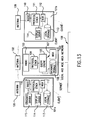
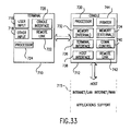
A further use for portable computer devices is the
electronic mail box or mail delivery service application.
Referring to Figs. 13 to 15 the invention provides an
improved architecture for electronic mail box systems
including portable computer devices. The improved system
uses a distributed message delivery service architecture,
based on cooperating processes. Within a network a
particular machine is designated as a server and its
address becomes public on the local network. The server
is responsible for delivery of mail and reception of mail
and also provides other machines on the local network
with information regarding user message status, for
example whether a message has been received for an
identified user, in which case the message can be
forwarded to the user. The remaining machines on the
network are designated the client and carry out a
corresponding process, in particular providing a user
interface to the distributed mail delivery service. For
example the client portion can present various options to
the user for example the options of hearing audio
messages or viewing text or still images. The options
presented will, of course, be based on the resources
available to a particular machine, for example whether it
has a sound card and/or graphics capabilities.
Referring specifically to Fig. 13 there is provided
a server 100 and a plurality (shown as 2 in the figure)
of clients 101a,101b. The server 100 includes an antenna
102 for communicating with remote clients 101a,101b (for
example portable computer devices), a transmission and
reception module 103, a message coder and decoder 104
(protocol stack) and a processing module 105 (query
engine) for handling queries from clients 101, for
example regarding a particular user message status,
accessing any such messages etc. Information is accessed
from a memory 106 which may be a data base storage
module. The processor 105 also communicates with a mail
user agent (MUA) module 107 allowing user interface with
the server 100. The server 100 is further in
communication via the mail user agent 107 with a local
and/or wide area network designated generally as 108.
The service may form part of, or be configured for
connection with a telecommunications network or a
computer network, for example the "Internet".
Each client 101a,101b includes various modules
common with the server together with further modules
specific to the needs of the client. The client 101
includes an antenna 109 for communication with the server
and a transmitting/receiving module 110 communicating
with a message coder and decoder 111. The module 110
will include the hardware necessary for carrying out the
transmitting/receiving steps but it will be recognized
that at least some of the functions provided by the
module will be capable of being provided in software.
Indeed, generally, reference to modules need not be to
dedicated hardware but extends to programmed or
programmable software arranged to emulate hardware
performance. The message coder and decoder 111 interacts
with the mail user agent 112 providing user interface.
In addition the mail user agent 112 communicates with a
local data storage device 113 and with optional modules
such as a display driver 114 and/or a sound driver 115
(see client 101a) .
Operation of the distributed mail delivery system
may best be understood with reference to Figs. 14 and 15.
Fig. 14 displays the steps carried out by the user in a
typical "client process". On commencement of operation
the client auto-configures itself based on the resources
(for example sound or graphics) available on the machine
[step 120]. The user logs in and enters a password [121]
and a connection is established between the client and
the server [122] at which stage information entered
during the log-in and password process is sent to the
server for verification [123]. If, however, the server
is not ready for communication then the procedure is
exited [124] and must be recommenced at step 120 or step
121. After the user status is queried [123], if the user
or password is unknown to the server the process returns
to step [121] and the log-in and password procedure is
re-initiated. Otherwise the options available to the
user are retrieved [125] in steps discussed in more
detail with reference to Fig. 15 and displayed as headers
to the user [126]. The user then enters his selection
[127] and the selection type is determined [128].
The client assesses whether the user wishes to view
a message [129] and if so retrieves the selected message
from the server [130] in a series of steps described in
more detail below with reference to Fig. 15. The client
then determines the message type, for example audio or
visual [131] and dependent on the message type either
displays the text [132] or plays the sound [133]. The
client then returns to step [127] and awaits a further
user selection.
If at step [129] the user indicates that it is not
desired to view a message then a message is created
[134], recorded [135], the data of the message is
packaged appropriately for transport [136], for example
by the protocol stack 111 shown in Fig. 13, and is sent
to the server [137] by the transmitter 110 and antenna
109. The client then returns to step [127] and awaits a
further user selection.
The client machine includes suitable input means,
for example a keypad and display means for example an LCD
display for the entry of user selection choices, message
information and for the display of messages. In addition
a speaker and microphone may be provided for the recordal
and playback of audio messages. A portable computer
device such as that shown in Fig. 9 may, for example, be
used as the client 101. In that case, auto-configuration
of the client is carried out partially in dependence on
the type of module 22 inserted into the main body 21 of
the portable computer device 20.
Referring now to Fig. 15 the steps of a typical
"server process" are shown. The server operates as a
continuous process but, in order to save system resources
is mostly in a stand-by mode where it simply listens to
the local network. Accordingly in step [140], on
initiation, an open end connection is established and the
server monitors the connection [141]. If any queries are
received [142] the server proceeds to the subsequent
steps but otherwise continues to monitor the connection
[141]. On reception of a query the server "wakes-up",
interprets the query to establish which of the internal
modules of the server is designated [143] (for example
data base storage 106 or mail user agent 107) and if the
request is valid [144] the request type is determined
[145]. The request may be a HEADER which is sent to the
client to present user message headers (corresponding to
steps [125] and [126] shown in Fig. 14); accordingly at
the request for a header [146] appropriate information is
retrieved [147], is packaged for transport [148] for
example at modules 104,103 of the server and is sent to
the client [149]. The server then returns to monitoring
mode [141] listening to the connection with the remainder
of the network.
If at step [146] the request is not for HEADER
information then the server retrieves any user messages
[147] that are stored in respect of the identified user
(for example on the basis of the log-in or password
information entered at the client) and the data is
packaged and sent as described above in relation to steps
[148,149]. The system then returns to monitoring mode
[141].
It will be seen that steps [142-147] are carried out
by the query engine 105 of the server, user message data
being retrieved from the memory device 106 of the server.
Where, at step [144] the request is not valid then
the user and request are logged and an error message is
sent back to the client [151]. The system then returns
to monitoring mode [141].
The system described above requires far less data
storage on the client terminal/computer and thus is
particularly (although not exclusively) suitable for
hand-held computers with basic network capabilities. The
system thus resolves the problem of mail box locations as
well as releasing the hand-held host and the data storage
and retrieval responsibility by treating the mail
delivery service as two cooperative and independent
processors that communicate with each other using basic
network protocols.
In effect, unlike conventional mail delivery service
systems, the distributed mail delivery service uses the
underlying network to actively present enquiries to the
server regarding the message status relating to a
particular user, rather than using a directory structure
and relying on a file system. Because all enquiries are
directed to one server, multiple connections for a single
user can be identified and refused, the server is the
only point of connection to external entities, offering
a more secure delivery system and the server offers a
view of the mail delivery service to the end user which
is independent of the actual matter stored by the server.
In addition clients are relieved of the
responsibility of storing or directly retrieving any of
the actual data. Messages are delivered via the network
on a demand basis, that is when required by the user, and
the client portion of the distributed mail delivery
service simply translates user requests into a series of
commands which are forwarded to the server in the form of
queries. If the queries are validated the server returns
the necessary data to a client in response to the
queries. By virtue of the separation of tasks the system
designer gains the freedom to modify components of the
system independently. For example it may be initially
decided that the server should store messages using a
simple mail box scheme, but if the capacity or speed or
efficiency of the system subsequently needs to be
enhanced as a result of the increased burden placed on it
by an increasing number of users and messages, the server
can revert to using a complete database management
system. Any such modifications will, however, remain
hidden from the client portion and the client portion can
effectively remain unaware of the underlying structures
of the server indefinitely.
Similarly, the client portion may be modified for
example to move from a character-based user interface to
a graphical-type interface in which case the server may
remain unaware of the modifications as the basic data
query and exchange mechanism is unchanged, the server
remaining unconcerned about the manner of data
presentation at the client portion.
Accordingly a voice mail delivery system is
implemented. The client portion may run on a PC
compatible platform although it could be ported very
simply to other platforms. The server can operate on
UNIX or DOS platforms. The client requires less than
256kbytes of local storage.
It will be seen, therefore, that the proposed
delivery system offers multiple advantages over current
mail box schemes, providing flexible and independent
modules which are simpler to maintain and modify and
which offers a generic mechanism by which data transfers
can be implemented over data networks. As it is a
distributed system it does not require the presence of a
network file system and simply relies on local storage.
In particular, because a server is provided on each
local network for dealing with the clients within a local
network and also for communicating with other servers on
other local networks the roaming capabilities of the
system are enhanced. The distribution of mail processing
between the various local networks is in contrast to the
centralized hub system in conventional mail delivery
systems and allows simplified and accelerated mail
processing and transfer in combination with a roaming
portable computer.
Further aspects of the present invention will be
discussed in conjunction with Symbol Technologies Inc.
spread spectrum wireless networks: Spectrum One
(operating at a frequency range of 902 to 928 MHz) and
Spectrum24 (operating at a frequency range of 2.4 to
2.5GHz). However, the embodiments discussed are
applicable to other wireless communications systems.
Part 1: "symbol" Terminal Emulator Program (STEP) and
pen-based mobile units/terminals.
The "symbol" (a Trade Mark) terminal emulator
program (STEP) is a tool used to format applications for
pen-based mobile units such as the mobile unit 21 shown
in Fig. 9.
An example of the Spectrum24 system is shown in Fig.
16. The STEP resides in the mobile units 21 and works
with an enabler development system 160 on a host computer
162 to execute a predefined set of commands sent from the
host computer 162. The enabler development system 160
includes an enabler server 164, an enabler application
program interface 166 and a timer 168. The enabler
development system 160 receives input from the Spectrum24
access point unit 170. The host computer 162 is
controlled by a terminal 172 to run host applications
174.
The STEP provides the mobile units 21 with the
interface and logic functions necessary to communicate
over the radio network, and controls all input, output
and display functions at the mobile unit level, including
keyboards, displays, scanners and peripherals, and
printer support.
The STEP provides commands that allow the
administrator to create a selection of data entry fields
fro the mobile unit operator. For example, these
commands would permit the operator to: (a) enter data
from a keyboard and scan bar codes; (b) send multiple
messages to the host in the same transaction; and (c)
control the type of data entered and validate entered
data. Further, for display purposes STEP allows the
administrator to (a) display data at any location on the
mobile unit screen; (b) clear the entire mobile unit
screen or clear a single line; (c) save and restore the
mobile unit screen; and (d) control the backlighting
feature to view the screen in the dark.
The STEP acts as a power manager to reduce demands
on the batteries in the mobile units 21, enabling them to
operate longer between charges and extending their
overall life.
By installing STEP on the mobile units 21 forms can
be created and displayed on the display screen 23 (shown
in Fig. 9). Forms can include messages, prompts and data
entry fields. This permits an operator to recall a
stored form for execution on the mobile unit 21; repeat
the execution of a stored form for on-line batch
processing; and erase all stored forms and determine the
date and time of the last form definition.
The STEP enabled mobile units 21 allow the host
computer 162 to read data files stored in the unit 21;
sound the mobile unit's 21 alarm; interrupt mobile unit
21 input activity; and log off the mobile unit 21 from
the host computer 162. This allows the operator to use
the mobile unit 21 to collect data without being logged
on to the host computer 162; set and save system
parameters; download files from the host computer 162 to
the memory in the mobile unit 21; and perform other
maintenance tasks.
Fig. 17 illustrates a typical conventional flow
chart of the actions taken by the access point 170 when
it receives a packet of data from he mobile unit 21 on
the wireless network. If the packet is a registration
packet, determined at step 200, then the access point 170
processes the information carried by the packet at step
214. The type of association is determined by examining
the IP address of the mobile unit's 21 home access point
and does the control message exchanges accordingly at
steps 216 and 226. If the packet is not a registration
packet, as determined by step 200, then the packet is
decapsulated at step 202.
If the short term address mapping tables (ST-AMT) of
the access point 170 has an entry for the packet's source
MAC address, determined at step 204, then the packet has
originated from the mobile unit 21 that is away from its
home stationary data link (SDL) network and processing
passes to step 218. At step 218 the access point 170
encapsulates the packet within a UDP packet with the IP
destination address set to that of the mobile unit's 21
home access point.
If the long term address mapping tables (LT-AMT) of
the access point 170 has an entry for the packet's
destination MAC address, determined at step 206 then the
packet is meant for a mobile unit that is currently
outside its home access point group (APG) and processing
proceeds to step 220. At step 220 the access point 170
encapsulates the packet within an UDP packet with the IP
destination address set to the destination mobile unit's
local access point.
If the packet's destination MAC address is a
broadcast address, determined at step 208, then the
packet if forwarded at step 222 on its wired and wireless
interfaces. If the destination MAC address in the packet
appears in the access point's mobile host table (MHT),
determined at step 210, then the packet is encapsulated
within a wireless link layer packet and forwarded on the
wireless interface at step 224. Otherwise, the packet is
forwarded on its wired interface at step 212.
Part 2: Assigning domains and IP addresses to said pen-based
mobile units 21.
The following embodiments of the present invention
deal with assigning domains and IP addresses to the
mobile units 21 to operate in a wireless LAN technology,
such as the previously discussed Spectrum One and
Spectrum24 systems.
According to an embodiment of the present invention
the domains and IP addresses are hard coded. The hard
coded embodiment involves setting the domain and IP
address of the mobile unit 21 in the configuration files
associated with the Spectrum24 drivers and protocol
stacks.
The hard coded embodiment provides a relatively
simple implementation of domain and IP address assignment
for Spectrum24 network installations when only a few
mobile units 21 are used that always use the same APG on
the same network. In addition, a high degree of security
is provided since the ability to detect and assign domain
and IP addresses are available only in the configuration
area, not in the operational area.
The hard coded configuration of each mobile unit 21
ensures that the domain and IP address information are
non-volatile. This insures that even cold booting the
mobile unit 21 will not require reconfiguration. All the
access points 170 in the target APG can be configured to
use the hard coded domain. The server can be set up to
reserve permanently (without any timeout) the hard coded
IP addresses for use by each hard coded mobile unit 21.
Another embodiment of the present invention involves
the application-selection of domains and IP addresses.
This embodiment is suitable for situations where a system
administrator manually configures the mobile units 21
before their use by operators by setting the domain and
IP address. In particular, when mobile units 21 are the
only nodes on the network or when the system
administrator set domains and IP addresses by referring
to a master list maintained on a network server the
application-selection system is advantageous.
For situations where the operator must identify the
selections as he moves between APGs or networks a more
sophisticated application is provided to allow the system
administrator to establish logical names for domains and
IP addresses so that operators can pick the appropriate
settings by choosing a meaningful name such as truck,
warehouse, depot, etc.
The application-selection method allows for the
dynamic adjustment of domain and IP addresses under
application control across APGs and networks.
A further embodiment of the present invention
involves the access points-assignment of domains and
server-assignment of IP addresses. This method is
suitable when the manual assignment of domains and IP
addresses is impractical due to many mobile units 21 or
due to the complexity of the network.
AP-assignment of domains requires configuring access
points 170 to allow for an automatic configuration.
Using the access point 170 access control list (ACL)
features, security can be enhanced by giving the access
points 170 a list of the MAC-layer addresses of all the
mobile units 21 allowed. This list can be larger than
the number of mobile units 21 actually being serviced at
any given time, allowing the timesharing of the capacity
of the access point 170 among a large set of intermittent
use mobile units 21.
Server-assignment of IP addresses requires the
existence of a mechanism within the protocol stack,
supported by services and utilities in both the server
and the mobile unit 21, to allow dynamic allocation of IP
addresses. BOOTP and DHCP are two common mechanisms for
dynamic allocation.
BOOTP works by having a file on the server for each
possible mobile unit 21, selected by the mobile unit's 21
unique MAC-layer address, that provides the IP address to
be used for that mobile unit 21.
DHCP works by having a database on the server that
records the IP addresses that are in use (by MAC-layer
address) and the IP addresses that are available for
dynamic assignment. When a mobile unit 21 requests an IP
address, the database is searched for the MAC-layer
address. If an IP address is already allocated to this
mobile unit 21, the it is simply returned. If no IP
address is allocated to the mobile unit 21, and one is
available for dynamic assignment, it is allocated to the
mobile unit 21, recorded in the database and assigned to
the mobile unit's MAC-layer address, and returned to the
mobile unit 21. The DHCP server can set to timeout when
a dynamically assigned IP address has not been used for
some time and return it to the available list or to keep
IP addresses permanently assigned once allocated to a
mobile unit 21.
The domains and IP addresses can be stored in
volatile storage, but would need to be reentered
following a reboot. However, the necessary address
information can be stored onboard the flash of the mobile
unit 21, or on the Spectrum24 adapter card, or on RAM
disks or PCMCIA storage cards.
The AP/server-assignment methods provide the ability
to program ACL information via a personal computer
attached to the same hardwired router as the access point
170. Further, the AP/server-assignment methods allow for
automatic assignment of complying domain and IP addresses
as needed, and allow mobility across APGs and networks.
According to another aspect the invention addresses
the problem of the necessity of a specialized program for
parsing and interpreting high density data records
embedded in bar code labels. In accordance with the
invention it is proposed to distribute not only the bar
code data on a high density label, but also information
describing how to create an interface capable of reading
the data from the data record label.
Implementation of the invention will be familiar to
the skilled man in the operation of the Internet Web
Browser suitable for reading, for example, Hyper-Text-Markup-Language
(HTML) files. Those files are used to
describe an interface to be built by Web Browser. In the
present invention the mobile unit includes a reader or
Browser for scanning a high density bar code label that
contains a program script such as HTML, VB script or a
specialized compressed version of either. The script is
parsed and interpreted by Browser which constructs a user
interface at run time and presents it to the user. The
user interacts with the interface by scanning data labels
and interacting with any of the program's controls
presented to the user to properly process the data.
According to one aspect a new data or interface level may
be printed by the user that can be applied to the object
being processed. It will be appreciated that, as bar
code label densities increase, the capability of storing
the actual interface and the data record in a single bar
code label will appear.
Fig. 18 shows the system of the invention in more
detail. The system includes a Browser 300 to which bar
code information 301 is input. An interface 302 is
constructed at run time and an interface control 303 is
provided. The Browser 300 further includes a bar code
acquisition engine 304, a parsing engine 305, a printing
engine 306 with a printed data interface 307 and a
communications engine 308 with a communications
input/output interface 309. The user interacts with the
interface via a further interface 310.
It will be appreciated that the manner in which the
information is encoded in the bar code label will be
familiar to the skilled man, and that the software and
hardware required will also be familiar to the skilled
man.
This system is particularly advantageous with
respect to transportation and identification of goods.
The shipper of the goods can distribute a program script
label with the goods that is read by the receiver's
Browser. The program script label shipped with the goods
contains the information required to allow the Browser to
create an interface at run-time to read and process the
data for the container of goods shipped.
Logistical systems benefit greatly from a system
such as this, because unidentified materials in the field
can quickly be identified and processed by any unit
containing the Browser.
The administration of the hardware and software
contained in these systems is greatly reduced, because
the Browser contained in the Mobile Unit (MU) stays
static. Only when new Browser features need to be
distributed do the MUs need to be updated. All
interfaces are distributed on high density barcode
labels. This system of application program distribution
truly makes the computer system general purpose. An
infinite number of different interfaces can be read in
and executed by the Browser. No longer are users limited
by secondary storage on their MUs for storing application
programs.
Using this new system, any computer system equipped
with a general purpose interface reader application
(Browser) can create an interface "on-the-fly" that is
capable of reading processing information on the
accompanying data record labels.
Systems deployed in the field no longer need their
application programs updated when changes to the program
file is required. Only the program script label need be
replaced. The number of different data formats that can
be processed by a particular computer system is limited
only to the number of program script labels available to
the user.
Different users of such a system can freely exchange
information because the interface information needed to
process the data files is distributed on a label along
with the data files themselves. Each user no longer
needs a copy of the specialized application program that
was previously required to read the data label.
According to another aspect of the invention there
is provided a bar code scanning OLE (Object Linking and
Embedding) COM (Component Object Model) object for
communicating commands and bar code data over a wireless
link. As discussed in more detail below the object uses
OLE automation to be a "plug-in" development OLE control
extension. It thus becomes an in-process OLE automation
object. The in-process OLE automation object controls a
bar code scanning device over a wireless link on a remote
client. The remote device enables a bar code reader and
collects the bar code information, returning the data
over the wireless link to the OLE automation object.
The general principles of OLE architecture will be
well known to the skilled man. In the present
embodiment, a scanning object is implemented as an OLE
control. OLE controls are re-useable software components
designed to work in containers that support OLE 2.0. OLE
controls are more powerful and more flexible than
previous systems such as VBX Custom Controls in
particular as, unlike the VBX Custom Controls that they
are replacing OLE controls support 32 bit environments
and are not limited to Microsoft Visual Basic (Trade
Marks) .
OLE controls are designed to work in any container
that supports OLE 2.0 including not only Visual Basic 4.0
and beyond but also OLE-enabled container applications
such as Microsoft Office (Trade Mark). Additionally OLE
controls work in third-party OLE-enabled applications in
development tools.
OLE architecture enables different software objects
to communicate to each other using a binary interface
mechanism. This allows software objects to be developed
separate from each other and bind very late at run time.
The software interface is a contract between the
container and the control on how the two software objects
will interact and exchange information.
Under the OLE architecture, the scanning object can
be placed and activated in any of a variety of containers
that support the OLE container interface. Fig. 19 shows
the general mechanism between a control 401 and its
container 402. As can be seen the mechanism includes
standard compound document interfaces 403 and additional
control interfaces 404, each comprising multiple
interfaces.
In such a system the scanning control appears to
become a seamless part of the container's environment.
Through the exposed interfaces the two objects
communicate and integrate with each other.
In addition, as shown in Fig. 20, the scanning
control 401 communicates over a wireless link 410 with a
remote computing client 411 to control the bar code
reading device 412. The scanning control 401 sends
commands over the wireless link 410 by creating separate
threads of execution 413a to 413d that send, receive and
synchronize bar code reader transactions over the
wireless link. As shown in Fig. 20, the OLE container
402 and control 401 communicate via lines 414a to 414f.
The OLE control includes a main control thread 415 which
communicates with the OLE container 401 via lines
414a,414b and with a first transaction thread A 413a via
a line 416. Each of the transaction threads 413a to 413d
communicate along a respective line 414c to 414f with the
OLE container 402. Each of the threads also outputs
through a respective first line 417a to 417d to a
transaction start dispatch function 418 and receives an
input via a respective second line 419a to 419d from a
transaction complete dispatch function 420. The
transaction start dispatch function 418 communicates with
a transport layer 421 in the remote client 411 via a line
422 and a transaction complete dispatch function 420
receives input from the transport layer 421 via a line
423. The remote client 411 includes a corresponding
transport layer 424 which outputs via a line 425 to a
data arrival handler 426 and receives an input via line
427 from a command complete handler 428. The data
arrival handler 426 outputs via line 429 to a bar code
device driver 430 and the command complete handler
receives an input 431 from the bar code device driver
430. The bar code device driver 430 communicates with
the scanning hardware such as a bar code reader 412 via
a line 432.
As a result users can develop applications using
OLE-enabled development tools like Visual Basic 4.0. The
user simply inserts a new scanning object into their
project, sets required properties, writes necessary code
for event notification and the scanning control
seamlessly talks to the remote client bar code scanning
device over the wireless link. To the application
program it appears as if the scanning device is resident
on its local hardware. The invention comprises a
significant development over previous architectures
comprising implementation of a local bar code scanner
resident on a machine running a COM object. In
particular the architecture of the invention allows
control of the scanner through the wireless interface.
By virtue of the present invention there is in
addition the capability of supporting future versions to
be distributed via the distributed component object model
architecture (DCOM). The interfaces between the control
container and the control itself are binary and can be
implemented by the operating system as Remote Procedure
Calls (RPC's). Accordingly the OLE control can be
implemented as an Active-X control to control devices
over an Internet or Intranet link. This technology
allows Web authors and developers to create a new
generation of interactive Web pager and applications, for
example Microsoft Internet Explorer 3.0 (Trade Mark).
This implementation is of particular benefit in proposed
systems whereby users will wish to integrate bar code
scanning capabilities into their Intranet/Internet-enabled
applications.
The Intranet arises from the application of Internet
technology to provide industrial strength mission
critical applications to users within an organisation on
an isolated LAN (Local Area Network) rather than for
external connection to the global internet. Single
function handheld computing terminals can then be built
that connects to the LAN and execute predetermined
applications to reduce significantly the cost per client
when installing a network system. In an Intranet system,
mission critical applications reside on the server,
eliminating the cost of application deployment and
lowering the cost of terminal configuration. The data
collected is transmitted and saved on the server so
little or no local data storage is needed on the handheld
terminal. It will be seen, therefore, that such a system
provides an ideal forum for the OLE scanning control
object discussed above.
A conventional Internet link is shown referring to
the schematic diagram at Fig. 2a, and block diagram of
Fig. 2b and includes a remote terminal data device 501
comprising, for example, a lap-top computer, a PC or a
mobile unit as discussed in more detail below linked to
a server 502 via a suitable link 503 which can be a
telephone link, incorporating a suitable modem, a
wireless link or a cellular telephone link amongst other
possibilities which will be evident to the skilled
person. The server 502 is in turn interconnected via
line 504 to the Internet shown schematically at 505.
When the user wishes to access a web site the web site
address is entered at terminal 501 and server 502 brings
up the web site 506 at the given address from the
Internet 505. Similarly when the user wishes to create
a site, the relevant information is entered at terminal
501 and the site is created via server 502.
Whilst the system shown in Fig. 2a allows
centralised site access and creation, it will be
appreciated in certain circumstances the system is
cumbersome, for example where it is desired to create a
site very quickly. In addition, whereas in some
circumstances a user will simply know what information is
sought, and will "browse" through the Internet to find a
site containing that information, in some circumstances
the user may be entirely aware of the exact site which he
wishes to access irrespective of the information
contained at the site. In that case the centralised
system shown in Fig. 2a can give rise to unnecessary
delays.
An improved system according to the present
invention is shown as a block diagram in Fig. 2c.
Briefly within the client terminal 501 itself suitable
server software 502 is retained. Accordingly the client
is able to create an Internet site directly, the Internet
site 506 being stored at the server again directly at the
terminal 501. The client/server then accesses the
Internet 505 via a line or wireless link 504. As is well
known, the Internet can be accessed generally by access
points AP1 to APN.
As a result the invention allows a Internet site
such as a web site to be set up at the terminal without
the requirement of accessing a dedicated server, as
appropriate server software is included at the client
terminal. When a third party wishes to access the site,
they will have or be able to obtain details of the client
server address and can thus access the client server via
the Internet.
A particular implementation of the invention arises
in relation to client/servers provided in remote, mobile
terminals communicating with the Internet via an access
point with which it is in wireless communication. In
that case data is entered at the mobile unit, generally
relating to the physical environment at which the mobile
unit is presently located such as an image of the
surrounding scene. Users wishing to access that data
merely need the client/server address. The address is
entered at the relevant access point to the Internet and
the site is pulled up directly from the client/server.
It will be seen that the client/server can include a home
page which is actually pulled by the user, the specific
sub-pages at the site being accessible via the home page,
once the home page has been accessed.
The system can use a data terminal of the type
designated generally 510 in Fig. 3a. The central
elements to the data terminal 510 comprises a digital
camera having a lens 512 and a wireless Internet link
518.
Digital cameras are well known and the detailed
structure will be apparent to the skilled man such that
a detailed description is not required here. Briefly,
however, the digital camera includes a lens system 512
for focusing an image onto a CCD (charge coupled device)
array. The image is thus pixelised and encoded, for
example as a bit stream. The encoded signal is decoded
and displayed on a visual display screen 514 or output as
hard copy. A "still" image is obtained in the same
manner but by recording an instantaneous image. The
majority of the components of the digital camera are not
shown in Fig. 3a for the purposes of clarity. A CCD
camera is preferable over, say, a laser camera as images
can be recorded from a greater distance.
The data terminal 510 further comprises a keyboard
516. In order to record an image the lens 512 of the
data terminal 510 is directed at the scene to be
recorded. This is preferably displayed on the visual
display screen 514. When a desired image is isolated a
button, for example on the keyboard 516, is pressed and
a still image recorded.
In the embodiment shown, the data terminal 510
further includes various optional and required
components. The principal required component is a
wireless signal transmitter 518 which, as discussed in
more detail below, relays the recorded image to a remote
access point for distribution from that point.
Optionally the data terminal 510 further includes a
microphone 520 for recording, for example, a verbal
description of the recorded scene, a bar code reader 522
allowing alternative or complementary operation of the
data terminal 510, a physical interface 524 for
downloading of information stored in the data terminal
510 to a terminal to which it is connected by cable or
other link and a printer output slot for outputting a
hard copy of the image, additional information, or as
discussed in more detail below, a bar code symbol
representative of the stored image. In addition, as
discussed above, the terminal further includes server
software allowing creation of a web site at the terminal.
The web site can contain, for example, recorded images or
sounds from the environment of the terminal together with
text input at the keyboard and/or the user's recorded
verbal commentary. A further feature that can be
incorporated into the terminal is a global positioning
system (GPS) of a known type. The GPS communicates with
GPS satellites via a suitable antenna (not shown). As a
result the specific geographical location of the mobile
device can be immediately ascertained. This can be
provided as additional information broadcast by the
device and can also be used by a central tracking system
to ascertain where all the devices are at a given time.
Once again specific details of the various
individual components will be well known to the skilled
reader and, for the purposes of clarity, are not repeated
here.
In order to minimise costs the network architecture
is designed to minimise the amount of data traffic over
the highest cost communication links. This can be done
for example by selecting a communication route which
utilises the cheapest available lines. Where this can
lead to delay a prioritisation system can be introduced
ensuring that communications in respect of which delay is
unimportant can be sent on a cost optimised basis whereas
those signals for which the speed of transmission is
important are sent on a urgency basis. For example where
wireless communication gives rise to high costs as
against physical interface communication, low priority
information can be downloaded physically from the
terminal to a cradle to reduce the power and processing
burden and general cost burden.
An alternative terminal configuration can be based
on the arrangement disclosed in US Application Serial No.
08/691,263, filed August 2 1996, assigned herewith. That
specification describes a modular type terminal having
interchangeable data collection modules, together with a
detailed discussion of communications between mobile
units and the Internet.
The system can be used for coverage of news events.
A journalist holding the terminal can store images of a
news event, and record a report on the event. A web site
can be instantaneously set up at the terminal via the
internal server holding the report and other data.
Accordingly a user wishing to find out about the news
event merely needs to access the site via the network.
The address could be known to the user or could be
available from a central site on the Internet disclosing
where various mobile units are located, and providing
their site addresses. It will be seen that the
technology could further incorporate a pay-per-view type
system whereby the user is automatically billed for
accessing the site. It will be seen that many other
applications can be envisaged. For example a police
report of the scene of an incident, or an insurance
operative report can be accessed actually on location at
the incident rather than relying on transfer to a stand-alone
server for creation of a web site at that level.
According to the embodiment any suitable form of
wireless communication between the client/server and the
Internet can be utilised. Such systems are well known
for roaming units, whereby access points to the Internet
arranged to receive communications from mobile units are
located at various geographical points. Known algorithms
can be used for selecting which access point is the most
suitable. The communication can itself be by radio waves
or an optical link such as an IRDA Standard Protocol. It
will be seen that another of the advantages of the system
is that the site is stored at the terminal and need only
be down-loaded on demand via the wireless link thus
reducing the cost that would be incurred by transferring
data continuously. Data that is never requested can be
transferred over a less costly connection at a later
time.
Referring to Fig. 2d a flow chart of the operation
of the terminal 501 is shown. At step 5110 the desired
data, for example an image or an audio recording is
captured. The data is then encoded at step 5112 into a
suitable format to be rendered as a web page, for example
by creating a bit map. At step 5114 the encoded data is
processed to create a suitable web page according to the
desired format, as determined by the server software and
any user input. The process can then branch to step 5116
where the page is stored at the terminal. When a page
access request is received at 5118 by a remote user
called up the known address for the terminal the page is
displayed at the terminal web site. According to an
enhanced system, the process branches at 5114 also
allowing a specific page address to be created for the
particular data stored in the given process, at step
5120. The address and details of the page stored at the
address are displayed on a home page at step 5122. This
allows a menu to be created for the terminal such that
more than one page is available. Accordingly when the
site is accessed at 5124 by a remote user the remote user
has the option of selecting the relevant sub-page
displayed at the home page at step 5126, allowing display
of any desired page, returning to step 5120. The system
thus allows quick and easy operation with no programming
required and in particular no HTML requirement. An
instantaneous web page can be set up using the server
software, the image to be displayed being stored simply
by pointing the terminal at it and "clicking". Once
again, the system can be designed with cost optimization
in mind, ensuring that a minimum amount of data traffic
occupies high-cost communication links.
Referring to Fig. 3b one possible implementation of
an alternative embodiment of the present invention is
shown. Where, for example, the police or other
authorities, or an insurance operative wish to record
details of a scene shown generally at 530, the image is
captured as a still digital camera image by the data
terminal 510 in the manner discussed above. The stored
image is encoded, for example as a bit stream and the bit
stream is transmitted or relayed via the transmitter 518
to a remote point.
In the embodiment shown the image information is
relayed from transmitter 518 to an intermediate booster
transmitter 532. This can either be one of a network
spread across an area or can, for example, be carried in
the data terminal user's vehicle or a carrying case. The
use of a booster transmitter 532 reduces the broadcast
power requirements of the data terminal 510 allowing more
space to be dedicated to data storage/processing means or
accessories, and increasing the battery life. It will be
appreciated that the booster transmitter is, however,
optional and in many cases will not be required.
Transmission can take place via a RF wireless link
microwave or other suitable wireless communication
method. Where the vehicle is part of a larger GPS
monitored tracking system the arrangement of the present
invention can be a module incorporated into the system.
Either the transmitter 518 in the data terminal 510
or the booster transmitter 532 relays the image
information to an access point 534 including a receiver
for receiving the relayed information signal. The
received signal is input to a processor/data
storage/decoder device 536. The image can then be
transferred to any desired device, for example a central
data storage device for the user to access on return to
his premises (for example an Intranet or LAN), or a news
and information network (such as the Internet) where it
is desired to broadcast the image, or to a police or
other authorities' information database where it is
desired to record and document the image. The
transmitted signal from the data terminal 510 may also
include information such as the desired destination of
the image, additional information relating to the
circumstances, encoded information representative of
recordings of any verbal messages or recordings of sound
messages further explaining the circumstances as recorded
by the microphone 520. Information relating to the
circumstances, or the destination of the image can be
input via keyboard 516.
Where the web page is created on site at the
terminal using a internal server, the transmission system
described above can equally be used for third party
access to the web page.
A block diagram showing the components of the data
terminal 510 is illustrated in Fig. 4. The data terminal
includes various inputs comprising suitable transducers
for converting the input signals to electronic signals.
The inputs include the digital camera input 544 including
a CCD array transducer, an audio signal input 546
including a microphone transducer and a bar code symbol
signal input including, for example, a CCD array. Each
of the signals is input to an encoding or digitising sub-processor
respectively 550,552,554, and the processed
signal from each sub-processor is transferred to a data
storage and processing device 556. The data is stored,
processed and relayed as appropriate to various outputs.
Data relating to the image captured by the digital camera
544 and, as appropriate, any bar code data or audio data
is transferred to a transmitter module 558 and is
transmitted as described above at output 560. A hard
copy of the still image, or, as discussed below, a bar
code symbol representative thereof is output via printer
drive module 562 and output 564. Where it is desired to
download stored information via a physical interface this
is done at output 566. In addition the data
store/processor 556 receives information input to the
keyboard 516 via a line 568 and sends the image from the
digital camera input 544 to the visual display screen 514
via line 570. The system as a whole is powered by power
supply 572, for example a battery. Where the terminal is
configured to create a web page on site, a server can be
incorporated in hardware (or software or a combination of
hardware and software) as shown at 557.
Accordingly it will be seen that in one aspect the
image data can be captured automatically and transmitted
to a common database accessible to authorised users. The
images could be transported and/or accessed via video
servers, collaborative work group software and
distributed multimedia, and implemented by desktop video
teleconferencing. Processing of the image can be carried
out on the raw data once it has been transmitted to the
main network, allowing a further reduction in the
processing requirements and hence the power and space
requirements for the data terminal itself.
A particular advantage of using a digital camera is
that the image can be stored at high to medium resolution
and transmitted electronically with a minimum of
intermediate processing.
It will be seen that a wide range of applications
are available, in particular relating to industries
generally in which photographic (digital) images are
regularly taken in the field. An alternative to the
insurance claims documentation application discussed
above, where bids/estimates were involved the item in
respect of which the bid/estimate is provided,
documenting for example the work required on the basis of
which the bid or estimate was based could be recorded.
Similarly where repair work or improvement work was
contemplated, an appraisal could be made taking into
account stored images. The system could be used as a
general aid to documentation of items or circumstances.
As discussed above, the system could be implemented in
law enforcement. For example the scene of a crime or an
accident could be stored and relayed or accessed. Indeed
felons could be photographed and the image compared
against a suitable database for identification purposes
using known image comparison techniques. The system can
also be used as a preliminary aid to more exhaustive
documentation of circumstances such as proofing and/or
test shots. The data is preferably relayed as determined
by a network architecture designed to reduce transmission
costs by minimising transmissions over high-cost
communication links.
As will be seen for all of the above possible
applications and all other applications the system
includes particular and significant advantages, in
particular providing immediate access to images for third
parties privy to the image distribution network,
providing access to all users simultaneously as desired,
expediting processing time (as a result of immediate
accessing), improving accuracy and/or efficiency, as a
result of the availability of more precise information in
particular in high resolution implementations, and
associated cost savings in particular resulting from
decreased processing time and improved accuracy.
Yet a further possible implementation of the
arrangement would be as a remote fire alarm or smoke
detector. A terminal including the basic components of
a digital camera or other image recordal means and
network connectivity can be permanently or detachably
mounted at a zone where it is desired to monitor for
fire, smoke, poisonous gases or any other such hazard.
The terminal further includes a hazard detector of any
suitable type such as a smoke detector, a heat detector,
a noxious substance detector or other. All these
detectors are well known to the skilled man and do not
require further description here. In the case, for
example, of a fire alarm terminal, when a heat detector
detects that the ambient temperature has risen over a
preset limit the terminal is activated to capture a still
or moving image of the scene. At the same time the
terminal notifies the relevant authorities such as the
fire services and the image is transmitted in a manner
discussed above to an access point at the fire station.
Accordingly the scene can be reviewed and it can be
assessed whether a true fire risk exists or whether other
activity to which the increase in temperature is
attributable can be detected such as cooking activity.
As a result false alarms can be to a large extent
avoided. It will be seen that a similar approach can be
adopted for other hazard detectors, where an image of the
scene is transmitted to suitable authorities when a
potential risk is first detected for further assessment
before full mobilisation.
A further implementation for which the system of the
present invention according to a further aspect would be
particularly suited and which would benefit from the
advantages discussed above is in the field of goods
transfer, for example parcel delivery. When a damaged
parcel is received there is no way to know immediately
the condition of the parcel when shipped. The system of
the present invention would, however, be able to acquire
the image and transmit it to a remote location or create
a suitable web page on site. The image could then be
accessed at the receiving depot and compared with the
actual received parcel to establish whether the condition
had changed in any way. An alternative option would be
to print the image information in a bar code format, the
bar code itself being attached to the parcel itself. The
bar code symbol could be decoded at the receiving depot,
once again to compare the image with the received parcel.
Evidently a high resolution bar code symbol will be
required, for example under protocol PDF 417. The reader
shown in Fig. 3a includes the capability for such an
arrangement including a printer and printer slot 526.
It will be appreciated that the embodiments
described above relate to specific possible
implementation of the invention, and that the invention
embraces a number of alternatives. For example, as shown
in Fig. 5 the data terminal 510 is configured with
ergonomic considerations in mind, fitting comfortably
into the palm of the user's hand. As a result the data
terminal 510 can be quickly and accurately directed
towards an image to be recorded, using the visual display
screen to ensure that the image is as desired. At the
same time the keyboard can be manipulated comfortably
using the user's other hand to capture the image, input
additional information and so forth. Alternatively the
terminal may be in the form of a conventional camera, or
a video camera, or any other appropriate configuration
allowing image capture, and, preferably, data input.
The digital camera preferably includes auto focus
capabilities and manual zoom capabilities with a separate
button/trigger for zooming, which button/trigger may form
part of the keyboard or may be provided separately. The
manual zoom feature will assist in taking close-ups of
the subject to be imaged. As mentioned above, a printer,
for example a low density, low quality printer can be
included in the data terminal, or provided as an add-on,
so that a hard copy of the image is available in the
field. As also discussed above, the image could be
printed in PDF 417 format for subsequent decoding.
Fig. 8 shows an alternative configuration for a data
terminal. The terminal 510 contains generally all of the
components discussed in relation to the other embodiments
herein. However the terminal 510 is configured in a
"point and shoot" design and includes a grip portion 5120
and a barrel portion 5122. The grip portion is
configured to sit comfortably and easily, with optimum
balance, in the user's hand and further carries a trigger
5124 and a thumb wheel 5126. A display 5128 and optional
keypad 5130 are provided on the upper face of the barrel
portion 5122 to allow easy viewing and input access to
the user. The camera lens or other image recordal means
are provided on the front face of the barrel portion 5122
(not shown) allowing the user simply to point the
terminal 510 in the direction it is desired to record in.
When the desired scene is viewed on a display 5128
capture is effected by activation of the trigger 5124.
Zoom can be controlled by the thumb wheel 5126 which is
preferably located for optimum ease of use by the user's
thumb when the grip portion 5120 is held by the user.
The processing speed and storage capabilities of the
components of the data terminal can of course be
determined according to the eventual cost of the system,
for example a slower and hence cheaper microprocessor can
be incorporated. For more high-end applications the data
terminal could additionally include an SRAM card to store
the still images. In addition the visual display screen
514 can, as shown in Fig. 6 include LCD (liquid crystal
display) capabilities. Accordingly using a suitable pen
100, the image can be altered for example by ringing or
otherwise highlighting areas of interest, the alterations
being represented on the LCD display as 5102 in Fig. 6.
The alterations can be deleted or revised additionally
using the keyboard as appropriate.
The range of implementations, and the speed and
efficiency of the system can be further enhanced by also
incorporating bar code reader capabilities into, or in
conjunction with, the data terminal. The construction
and applications of bar code readers will be well known
to the skilled man and do not require a detailed
description here. Briefly, however, a bar code symbol
comprises one or more rows of light and dark regions,
typically in the form of rectangles or, for the case of
two-dimensional codes, in the form of a two-dimensional
array of light and dark spaces. The dimensions of the
dark and light regions indicate encoded information to be
read. A bar code symbol reader illuminates the symbol
using reading beam generating means and senses light
reflective on the coded regions using reading beam
detecting means to detect the dimensions of the coded
regions. A decoder decodes the detected encoded
information. Known symbols which include, for example,
UPC/EAN, Coder 128, Codabar and Interleaved 2 of 5.
One known type of bar code reader comprises a data
wand as disclosed in US Patent No. 4,471,218,
incorporated herein by reference.
Fig. 7 shows a data terminal 510 of the type
described herein above further incorporating an optical
reader 5110 incorporated in the data terminal 510. The
reader 5110 includes reading beam generating and
detecting means and the data terminal 510 includes
processing means for decoding the detected encoded
information. The reader 5110 may comprise either a
"flying-spot" laser scanner including means for scanning
the reading beam or a "field of view" optical reader
including a CCD array as detector. Both types of reader
will be well known to the skilled reader and a full
description of the components and operation is not
provided here.
It will be appreciated that a wide range of
implementations can be envisaged for the data terminal
510 shown in Fig. 7. In particular it may be useful in
many circumstances to be able to read information encoded
in bar codes to adduce additional information to that
retrieved by the data terminal from the external
environment.
A particularly advantageous embodiment is shown in
Fig. 7. In particular a book or other printer matter
5114 is provided which can be carried by the user
including printed bar codes 5116 which are read by the
reader 5110 and the information contained therein
utilised by the data terminal 510. As discussed in more
detail below, the data terminal 510 in fact comprises an
Internet server capable of creating a web site at the
data terminal carrying, for example, information relating
to the external environment around the data terminal for
access by users elsewhere on the Internet. In such
circumstances the terminal might conventionally wish to
download executable code from a host machine using an
agent implementation language such as Java (a trade
mark). This system can be cumbersome and time consuming
in view of the level of communications required between
the client and the host. The present invention solves
this problem by storing the executable code (applets) in
the form of two-dimensional high density bar codes 5116
in the book 5114. Each bar code symbol 5116 is
identified by a suitable short title or other identifying
information in the book. When it is required to access
an applet the user is merely required to read the two-dimensional
bar code using the bar code reader 5110, and
the executable code is immediately downloaded to the data
terminal 510 for the data terminal 510 to use it as
appropriate.
The invention allows the user to carry a
conventional book - for example having five hundred pages
of 2-D applet codes. Such a book would not be cumbersome
and would indeed be attractive to many users. The system
allows greatly accelerated downloading of applets in as
little as fifteen seconds. Conventional downloading
systems would still be waiting for connection to the host
in that range of time scale.
It will be appreciated that any suitable executable
code could be stored in a desired language in the two-dimensional
bar codes 5116. A wide range of different
applets could of course be stored according to this
system and indexed appropriately. Indeed the system
could be used for fixed or dedicated clients as well as
the remote, mobile client data terminal shown in Fig. 7.
It will be seen that the data terminal can
communicate with any suitable data network, for example
an access point to the Internet, or to a closed dedicated
system relating to the user or to which the user
subscribes together with other users. Communication can
be by way of RF communication or, if appropriate,
infrared or microwave communication, or any other
suitable wireless communication method.
It will be appreciated that any of the features
discussed in relation to one embodiment can, as
appropriate, be incorporated in any other embodiment
without departing from the teaching of the present
specification.
As used in this specification and in the appended
claims, the term "indicia" broadly encompasses not only
symbol patterns composed of alternating bars and spaces
of various widths commonly referred to as bar code
symbols, but also another one or two dimensional graphic
patterns, as well as alphanumeric characters. In
general, the term "indicia" may apply to any type of
pattern or information which may be recognized or
identified by scanning a light beam and detecting
reflected or scattered light as a representation of
variations in light reflectivity at various points of the
pattern or information. A bar code symbol is one example
of an "indicia" which the present invention can scan.
An embodiment of an optical reader to be used in
conjunction with the present invention is shown in Fig.
22. Although a pen-type optical reader (often known as
a "data wand") is shown it will be appreciated that any
other hand-held configuration would be appropriate for
use in conjunction with the present invention. Although
specific constructional details are also discussed in
more detail below, it will be appreciated that data
storage/processing elements and optical reader elements
of known type can replace the specific components
discussed in a manner that would be well known to the
skilled man. A discussion of pen-type readers is found
in US 5,506,392, commonly assigned herewith and
incorporated herein by reference.
The pen-type optical reader (henceforth referred to
as a "wand reader") is generally referenced 690 in Fig.
22. It will be appreciated that the exact shape of the
wand reader as illustrated 690 may be exaggerated, for
example in width, in order to show more clearly each of
the principal components and how they interact. In the
embodiment shown, the wand reader 690 comprises a ball-point
pen 691,692 together with the optical reader 693
itself. The wand reader need not actually have writing
capability, or may be in the form of any suitable writing
implement such as a pencil, a fountain pen, a marker pen
and so forth. Indeed the optical reader sub-system
discussed in more detail below can be in a modular form
insertable into a suitably configured writing implement
housing of any desired type.
The writing element of the wand reader 690 is shown
schematically as a ball-point pen cartridge 691 together
with a projection/retraction mechanism generally
designated 692 and of any suitable known type. Evidently
it is desirable to reduce the size of those elements
691,692 as far as possible to allow maximum space for the
reader module.
The reader module is generally designated 693. The
components and construction of the module 693 will be
generally well known to the skilled man and are described
only briefly hereafter for the purposes of completeness.
The reader module 693 includes a light source 694, for
example, a laser or LED and a reflector 695. A reading
beam generated by the light source 694 is reflected by
the reflector 695 out of a reading window 696. The
reading beam is reflected by a bar code symbol generally
designated as 697, passes once more through the reading
window 696 and is received by a detector 698. Preferably
the reader module 693 is a field of view reader in which
case the mirror 695 is a fixed mirror and the detector
698 comprises a CCD (charge coupled device) array. Of
course in certain implementations a scanning system may
be used in which case reflector 695 is driven by a motor
schematically shown at 699 for scanning motion. The
light source 694, detector 695 and, if appropriate, motor
699 are connected to a processor, control and data
storage element 6100 in conjunction with a power source
6101. The processor element 6100 controls operation of
the various components and also acts as a data storage
and processing device for bar code information read by
the module 693. As discussed in more detail below, it is
desired to down-load the information stored in processor
element 6100 at a later stage to an external device.
Accordingly a data output port 6103 is provided fed by
line 6102, preferably adjacent to or in conjunction with
the reading window 696. The wand reader 690 may also be
used as a laser pointer in one embodiment, wherein the
output reading beam is used to highlight desired elements
during a presentation.
A particular implementation proposed according to
the present invention for the wand reader 690 occurs in
relation to consumer information access as shown in Fig.
23a. For example where a consumer 6120 carries a wand
reader 690 and is in a retail outlet selling products
6121, each of those products may carry a bar code symbol
6122 for example in UPC format. The consumer 6120 may be
interested in purchasing the product 6121 but may not be
willing to commit until further information is available.
There exists, therefore, a risk that the consumer will
forget about the product or, as previously, it may be
necessary to rely on a consumer 6120 chancing upon the
product or additional information relating to the
product, and his memory being jogged accordingly.
According to the present invention, however, the
consumer 6120 can read the bar code symbol 6122 using
wand reader 690. The bar code information is stored in
the processing element 6100 and, to the extent desired,
processed. In particular, information contained in the
bar code symbol 6122 relating to the product 6121 is
stored. As a result the consumer has an automatic
reminder of the product he wishes to purchase as well as
information relating to the product. Evidently, where
the consumer 6120 sees more than one product of interest,
the relevant information can also be stored, the storage
capabilities of the wand reader 690 being limited only by
the storage space in the processor element 6100.
A particular implementation of the present invention
allows the consumer to subsequently down-load the
information stored in the wand reader 690 in a manner
described in more detail below. In particular the
information can be down-loaded to a personal computer or
other access point to a computer or data network. The
down-loaded information can then be used in various
different manners. For example the product can be
ordered or additional information concerning the product
can be accessed. A particular implementation proposed
under the present invention is that the bar code symbol
accompanying the product contains sufficient information
for the personal computer or access point to the computer
network to access a site on the ad (or comparable data
storage system) . This site can contain additional
information concerning the product, information
concerning related products, price information, cross-references
to further related sites, and the capability
of ordering and paying for the product. This greatly
simplifies the purchasing process, allowing for example
a price check and also ensures that the consumer does not
forget a product which has caught his attention.
In addition, further information can be derived
according to the present invention. For example the
popularity of the product can be assessed for future
marketing purposes. Preferably the reader wand 690 has
a dedicated user and carries user identification
information such as credit card number, or other
identification carried under an approved system. As a
result, during purchase of the product details of the
transaction can be based on that information. In
addition a customer profile can be built up based on the
consumer's buying patterns.
The access point can be located within the retail
outlet allowing the consumer 6120 to access the
information on site and make a purchase decision before
leaving the retail outlet. Suitable access points are
discussed in more detail below. It will be seen that the
bar code symbol can be carried on the product, or as
shown at 6123 on the shelf adjacent the product.
Alternatively the products could be displayed graphically
on a chart and the bar code symbol shown on or adjacent
the product on the chart.
It will be seen that the system can be extended to
other applications. For example where an abstract of
text is printed together with a bar code symbol, the bar
code symbol can contain information which, when down-loaded,
can provide access to additional or related text.
Assuming high enough resolution, the bar code symbol can
even be read off a VDU or other visual display system in
a closed system in order to access additional information
on the Internet. The bar code symbol can follow any
appropriate protocol, for example UPC or EAN and is
translatable into the Internet Universal Resource Locator
(URL).
A further application for the system is described
with reference to Fig. 23b. A catalog 6278 which shows
a product 6294 and also includes various data relating to
the item number 6282, the quantity 6284, the color 6286,
the size 6288 and other information 6290. In addition
bar coded shipping information is stored at 6292 and
payment method at 6293. Such a catalog is of use, for
example in home shopping applications. The catalog can
also carry a bar code identifying the caller at 6280
which information can be used for consumer identification
at the purchasing stage. The particular implementation
according to the present invention requires suitable
down-loadable product information to be stored in the bar
code symbols. In particular, the item number 6282 can in
fact be in the form of a suitable computer network site
address. Alternatively the computer network site address
can be stored at the other information field 6290. The
remaining bar code symbols may not be required, as the
information can be stored at the site address, but the
embodiment shown allows alternative implementations
dependent upon the hardware available to the user.
The user scans the wand reader across the site
address field and, if necessary, across the user identity
field 6280 and down-loads the stored information to an
Internet (or other computer network) access point. The
remaining product information is available at the
Internet site and the options such as quantity, color,
size, shipping method and payment method can be input at
that stage. Accordingly a simple catalog-based home
shopping system can be set up. It will be appreciated
that such a system can be introduced in various
environments, for example when a passenger is in an
aeroplane a suitable catalog can be provided. Once again
the system allows the consumer to consider carefully what
products they should buy on the basis of all available
information, and also provides a useful prompt or
reminder concerning products which have caught the
consumer's eye to which the consumer is not yet
committed.
Where the bar code symbol is for use in conjunction
with the a or parallel system, the information contained
in the bar code symbol effectively comprises an a
address. When that information is down-loaded to a
personal computer the personal computer communicates with
a dedicated server which captures the a address and user
identification information and re-routes to the relevant
product information site, for example a web site for
information retrieval and delivery to the consumer's
personal computer. Accordingly, the down-loaded
information would enable the PC to go directly to a
relevant home page or a relevant sub-page. A resolution
server on the system could be used to collect information
from all users, not only for information purposes but
also for billing and routing purposes.
It will be recognised that alternative systems to
the Internet, and alternative access methods are
envisaged. For example the Internet could be replaced by
an Intranet or a local area network (LAN), accessible by
a limited number of users restricted either
geographically or by some form of access authorisation.
Instead of being down-loadable to a PC which processes
the site address information, pulls up the authorization
site and displays the product information, alternative
access points are envisaged. For example, following a
system such as the Citrix (TM) system, the down-loading
could be merely an access point or terminal with minimum
processing capabilities itself. The terminal transfers
the site address information to a host computer which
carries out the principal conversion to a URL, accesses
the web site and transfers the information back to the
terminal for display. In that case the terminal acts as
little more than a display and input/output device. It
is envisaged, therefore, that the system could embrace
the new generation "network computers" working on this
principal. The effect of such a system is a considerable
change in the architecture of the system allowing reduced
costs to the consumer who need only buy the low level
terminal for connection with a host computer linked into
the main network. As a result the proposed invention is
yet further desirable and accessible to the consumer.
Various alternative wand reader configurations are
shown in Figs. 24 to 26. Referring firstly to Figs. 24a
and 24b a reader wand 6130 includes a pen assembly 6132
including a ball pen cartridge for example of the type
sold under the trade mark Zebra F-refill and an actuating
mechanism 6134 of a known type rotatable to extend and
retract the ball pen cartridge. The wand reader 6130
further includes a trigger 6136 manually actuable to
enable a scan together with a cooperating internal switch
6138 under, for example, code ITT KSC 421. The reader
wand 6130 includes a wand tip 6140 for reading a bar code
symbol. A data output point is also provided at 6137.
The system is powered by a battery 6142 of any suitable
compact type. Also included is a beeper 6144 or other
audible device which can sound to indicate to the user
that a bar code symbol has been successfully read, that
the battery power is low, that there is little memory
space left and so forth. Different audible tones or
sequences of audible tones can represent different
warning signals. In addition the wand reader 6130 can
include a screen (not shown) carrying information as to
the status of the wand reader and any instructions for
use thereof.
Figs. 25a to 25c show a slight variant in which,
where appropriate, the same reference numerals have been
used as for Fig. 24. It will be seen that the exit
window for the reader (here shown as a laser scanner at
6131) is in an inclined face relative to the longitudinal
axis of the reader wand 6130, allowing improved
ergonomics in reading a bar code symbol. The reader
further includes a grip 6133, for example made of
leather, around a portion of its length allowing improved
user grip and comfort.
Fig. 26a and 26b show a further alternative
configuration schematically once again using the same
reference numerals where appropriate as in Figs. 24 and
25. Various methods of down-loading the information
are contemplated. Two approaches are shown in Figs. 27a
and 27b. In a preferred configuration shown in Fig. 27a
a personal computer is shown at 6150 being of the
portable type although a fixed type PC will also of
course suffice. The personal computer 6150 includes a
keyboard 6152 and a screen 6154 and can generally be of
conventional type. The personal computer 6150 includes
a data input port 6156 arranged to communicate with the
wand reader data output port 6103. In the embodiment
shown, the output port 6103 of the wand reader 690 is
touched against the data input port 6158 on the personal
computer 6150. Touching the input port 6156 firstly
commences the down-loading sequence and secondly allows
accurate and rapid communication between the wand reader
690 and the personal computer 6150. The interface
between the wand reader 690 output point 6103 and the
data input port 6156 can, for example, be of the "memory
button" or "touch memory" type for example as sold by
Dallas Semiconductors. The actual interface is of well
known type and in effect the information stored in the
wand reader 690 is communicated to a memory button 6103
provided at an appropriate point on the wand reader 690.
The information is converted to a suitable form for
transmission at the memory button 6103 and, on contact
with the data input port 6156 of the personal computer
6150 the transmission is activated. The data input port
6156 is configured to receive and convert into a suitable
form information transferred from the memory button 103.
In particular the information can be transferred in the
form of a series of electronic pulses representing bits.
Such a system gives rise to a simple and substantially
error-free interface allowing a user to down-load
information stored in a reader wand 690 to a personal
computer 6160 quickly and accurately.
As will be appreciated, various other down-loading
methods are contemplated within the ambit of the present
invention. For example as shown in Fig. 27b a fixed-type
personal computer 6160 including a keyboard 6162, a
display screen 6163 and a mouse 6164 includes a
microphone 6166 which receives an audio signal from a
corresponding speaker data output 6168 on a reader wand
690. A button (not shown) or other switch can be
included on the reader wand 690 to activate transition by
the speaker 6168. The information stored in the reader
wand 690 is converted to a high frequency audio signal at
the speaker 6168 which is received by the microphone 6166
and decoded. Of course the transmitter can transmit
other forms of radiation, for example it can be an
optical or microwave transmitter with a suitable receiver
being provided on the personal computer.
Where the transmitter is optically based it can
utilise IRDA (infrared) standard communications
implementation as will be known to the skilled person and
as currently available on many "laptop" computers. The
optical transmission can be at the "blink" (repetition)
frequency of the pen illumination source.
Yet a further down-loading system is shown in Fig.
28. A dedicated data down-loading port 6170 includes an
orifice 6172 for receiving a reader wand 690. The port
6170 communicates information down-loaded from the wand
reader 690 via a line 6174. Referring to the sectional
view shown in Fig. 29, it will be seen that the port 6170
includes a data receiving interface 6174 of any of the
types described above which communicates with the reader
wand 690 for down-loading of information. Down-loading
can be contact activated by contact between the wand
reader 690 and the interface 6174 or activated by pushing
a button or other switch (not shown) on the wand reader.
The interface 6174 communicates with a processor 6176 for
converting the down-loaded information if necessary into
a format appropriate for a computer network, and the
information is communicated to the computer network via
line 6173.
It will be appreciated that line 6173 can comprise
a wireless link or a telephone line,in which case an
appropriate modem can form part of the port 6170.
It will be seen that all of these methods comprise
a user-friendly system for down-loading scanned
information from a wand reader. Use of a data well-type
port of the type shown in Figs. 28 and 29 is particularly
suitable where it is not desired to rely on the consumer
having a PC or other home access to a suitable computer
network. The port can for example be provided at a
retail outlet or other point of sale. It should be noted
that the wand reader can also be writable via the data
port, personal computer or other means (even a bar code
symbol itself) to input user information of the type
discussed above. This would facilitate short term usage
of a wand reader allowing a given user to input
information temporarily for the duration of his or her
use of the wand reader.
In an alternative ergonomic embodiment the reader
includes the components discussed generally above but is
in a slightly different configuration. Referring to Fig.
30a and 30b the reader 6200 is approximately the size of
a conventional pen but, in cross-section to its
longitudinal axis, is substantially square. Furthermore
a scanning window 6202 is provided substantially at the
top of one of the side faces rather than at the end
itself. Referring to Fig. 30b it will be seen that an
alternative reading configuration is thus achieved
whereby the reader 6200 is held substantially parallel
to, rather than substantially perpendicular to a page
6204 to be read. Preferably in its embodiment, a display
window 6206 and on/off trigger 6208 are provided
substantially at the top of the opposing side face. As
a result the trigger 6208 can be controlled, for example
by the user's thumb, with optimum ease for ergonomic
reading. Similarly the display 6206 can be easily read
by the user. Of course a more complex keyboard and/or
display layout can be incorporated as appropriate.
Fig. 30c shows impartial cross-section internal
details of a reader such as the one shown in Fig. 30a and
30b. It will be seen that the arrangement shown in Fig.
31 includes a rounded front end. In practice this
arrangement can in fact be circular in cross-section or
square in cross-section as shown in Fig. 30a and 30b. It
will be appreciated that the arrangement shown is not
necessarily to scale. At the rear end 6210 of the reader
6200 one or more power cells 6212 are provided and
retained in place by suitable means such as a threaded
cap 6214. Mounted on a board 6216 for ease of assembly
are the principal reader components including a laser
diode 6218 and a reading mirror 6220. The reading mirror
can be scanningly driven by a scanner driver 6222
controlled by appropriate circuitry 6224 also mounted on
the board. Alternatively, of course, the system can be
arranged as a static, field of view reading device.
Mounted over the scanner window 6202 is preferably a
sheet of transparent material 6226 of any suitable type.
Also provided at the scanner window 6202 is a
photodetector 6228 which receives the light beam
reflected from the printed indicia. The reflector 6228
is connected to suitable processing circuitry at 6224
suitable to decode the information.
In yet a further embodiment, a wand or pen-type
reader of the type discussed generally above can be used
in the detecting of counterfeit money. Devices are known
for detecting counterfeit money based on various
parameters such as colour, print quality and so forth.
It is proposed to incorporate such a device into the
arrangements shown allowing yet a further option for
operation. There are currently proposals to include bar
codes on high denomination bills in which case the reader
could be used for the purposes both of reading the bar
code and detecting whether the bill scanned is
counterfeit. In countries where there are currency
restrictions, bills can be scanned upon distribution and
information retained in the reader. Upon downloading of
the reader using, for example, a data well, information
concerning the notes in circulation can be maintained,
yet further allowing prevention of counterfeiting.
The range of applications of the system as a whole
is evidently very wide. For example a consumer could use
the wand reader whilst on an aeroplane or in other areas
where access to the Internet or appropriate computer
network was not immediately available. In addition to
the applications described above, the system could be
used to store and access information concerning items in
many other applications, for example in warehouse storage
systems.
It will be seen that the above teachings relate to
any scanner type suitable for hand-held scanning and
being essentially portable, capable of reading a bar code
symbol or similar information carrying symbol. The
information can be down-loaded from memory in the hand-held
scanner by means of any suitable interface to a
personal computer or other access point or computer
network, and corresponding information called up from an
web site or corresponding main memory location.
Figs. 31, 32a and 32b show the basic components of
the system according to the present invention. A
portable terminal 710, for example a hand-held computer
of the personal digital assistant type which can
optionally carry scanning/barcode reading capabilities is
arranged to interface with a cradle 712 via a physical
connection. For example the terminal 710 is inserted
into a suitable recess 714 in the cradle 712. The cradle
712 is itself connected with a host system 715 which can
be a stand-alone computer, or part of an Intranet/LAN or
Internet/WAN.
The basic components of the terminal 710,712 cradle
and host 715 are standard and interconnected in standard
ways using known interfaces and communication protocols
except where otherwise indicated below. Accordingly full
hardware details of the components are not discussed in
detail here as they will be well known to the skilled
reader. A brief discussion of the various components and
their uses and interconnections is provided below,
however.
As shown in Fig. 32a the terminal conventionally
comprises a user input 716, an "other input" 718, a
display driver 720, a remote link 722, a processor 724,
a memory 726, and a cradle interface 728.
The user input 716 can comprise, for example, a
keyboard with which the user can input information to the
terminal. The user input is transferred to the processor
and further processed as discussed below.
The "other input" 718 can comprise, for example, a
barcode scanner or other reader, video camera input,
audio input or any other appropriate data input. Fig. 31
shows a terminal 710 including a swivel mounted barcode
reader head 718. The input information is transferred to
the processor 724 for further processing as discussed
below.
The terminal 710 preferably includes a display 719
for displaying information to the user. For example the
display may represent input data for checking purposes,
or carry instruction or error messages for the user, or
even communication messages transmitted from remote
points. The display driver drives the display and
receives display instructions from the processor.
The terminal can be a CRT type television display,
a flat panel LCD type display or any other suitable
display. The advantage of flat panel displays is of
course the low bulk complementary to the compactness of
the terminal as a whole.
A remote link 722 is provided allowing communication
between terminal 710 and the cradle 712 (or indeed any
other access point as defined by the operational
parameters of the system) by remote, wireless
communication such as infrared IRDA, microwave, RF or any
other suitable method. Data to and from the remote link
is processed by the processor 724.
The processor 724 can comprise any standard
processing system such as a CPU. The processor allows
centralised control of the other components as discussed
above and below, together with general operational
conditions of the terminal, data and power checks,
compatibility checks and so forth as appropriate.
Shown separate from the processor 724 is a memory
726, although this may be incorporated in the same unit
as the processor 724. The memory 726 allows long or
short term data storage for example of data received at
the user or other input 716,718, via the remote link 722
or, as discussed in more detail below, via the cradle
interface. Memory control, management and transfer can
be controlled by the processor 724.
The cradle interface 728 allows downloading of data
stored in the terminal 710 to the cradle 712 as well as
transfer of control or other data from the cradle 712 to
the terminal 710. Information to and from the cradle
interface 728 is processed by the processor 724 as
appropriate. As discussed in more detail below, the
cradle/terminal interface is a physical interface which
operates during, and can be enabled by, insertion of the
terminal 710 into the recess 714 of the cradle 712.
The cradle 712 also includes various components
shown in block form in Fig. 32a, both arranged to deal
with control and communication with the terminal 710 as
well as communication with the host and other peripheral
functions.
The cradle 712 includes a processor 730 for
controlling the remaining components as discussed below
as well as operational conditions of the cradle 712 and
general communication needs between the cradle 712 and
the terminal 710, between the cradle 710 and the host 715
and, where the cradle acts transparently, between the
terminal 710 and the host 715.
The cradle further comprises internal memory 732 and
external memory 734. Both of these are for storage of
information received from the host 715 and/or terminal
710 for transfer between the two, as controlled by the
processor 730. The internal memory can, for example,
comprise part of the processor unit 730. The external
memory 734 preferably makes use of external storage
devices such as disks etc.
The cradle 712 communicates with the terminal 710 by
virtue of a terminal interface 736 communicating with the
cradle interface 728. The terminal and cradle interfaces
are preferably physical interfaces as discussed above.
Information to and from the terminal 710 can be
controlled via a processor 730. The cradle 712 further
comprises a host interface 738 for communicating with the
host 715. The interface can be a wired interface or a
wireless interface of known type as appropriate. A
communication controller 740 can also be provided
additionally to control the various communication
protocols between the terminal 710, the cradle 712 and
the host 715.
A remote link 742 is provided in the cradle 712 for
communication with the remote link 722 in the terminal
710. The communication can, as discussed above, be any
wireless means of communication such as infrared IRDA,
radio or microwave.
The cradle 712 can also include various peripherals
of standard types found with computers generally such as
a printer 744 or other component such as an enlarged
display, a modem link to a remote host, additional
storage or processing capacity and so forth.
The cradle 712 communicates via the host interface
738 with the host 715. The host 715 can be a stand-alone
computer or part of a local area network such as the
Intranet. The Intranet can itself be part of the
Internet or another wide area network, and if appropriate
suitable security measures such as a "fire wall" can be
put in place.
Numerous applications and advantages are provided by
the system shown in Figs. 31, 32a and 32b. In
particular, all of the advantages of a hand-held terminal
are available, such as portability, ease of use, and
suitability for mobile uses. Particular applications
include inventorying, monitoring of transported goods,
point of sale use, stock exchange formulations, auctions
and so forth. Because the cradle includes a data
interface, information input to the terminal, for example
as keyboard input or barcode input can be stored short-term
in the terminal and transferred at regular intervals
to the cradle when it is inserted in the cradle. Once
the information is downloaded the memory in the terminal
can be cleared. At the same time control or application
data can be transferred from the cradle to the terminal
such that the terminal application can be changed or
updated as desired. The cradle further preferably
includes a battery charging module which connects with
the terminal when it is inserted into the cradle to allow
simultaneous battery recharging. This option is
discussed in more detail below.
The cradle then communicates the downloaded
information to the host, and allows communication of
update/application information from the host to the
terminal.
Accordingly the system allows rapid updating of the
host data base with information from the terminal whilst
requiring reduced memory capacity in the terminal. At
the same time the cradle allows significant time-efficiency
benefits, both in reducing user involvement in
data transfer to a minimum and in allowing the
utilisation of user down-time to download information.
The remote link further allows immediate update
capability where necessary, at the same time allowing
this capacity to be kept to a minimum (by virtue of the
regular downloading sessions) giving rise to a
corresponding reduction in power drain.
As discussed in more detail below, particular
benefits of the invention lie in a system in which the
basic system described with reference to Figs. 31, 32a
and 32b is enhanced, and memory/computing tasks
distributed so as to allow maximum flexibility and
minimum demand on the terminal 710. Known hand-held
computers are continually being updated and redesigned to
allow maximum memory capacity, data storage and
application availability. Generally this involves
increasing the cost and complexity of the system, and
will lead to increases in weight and bulk which is of
course undesirable in a portable system. In addition the
overheads on the system are very high - updating of the
computer is costly and must be done on an individual
basis, and based on added peripherals or software that
will carry a considerable cost burden. This tendency to
increased, internal capacity and capability leads to a
greater risk of defect or error and the attendant
disadvantages. Such systems are currently known by the
term "fat clients".
The present invention, on the other hand, allows an
"ultra-thin client". In principle, this is achieved by
reducing the computing and memory burden in the terminal
to the greatest possible extent and incorporating that
burden instead within the cradle or, if possible, in the
host itself. This also allows the cradle 712 to operate
as a "thin client". As a result the terminal includes
the minimum capacity for user interface, including the
display capacity, user or other input capacity, minimal
memory and processing capacity and the communications
capacity discussed above. The cradle/host thus acts as
the true computer, carrying a majority of the processing
and memory capacity, including disk drives, communication
interface and so forth. Because the cradle acts as a
thin client, its simplicity and adaptability can be
maintained by ensuring that as much processing as
possible is carried out at the host.
A basic architecture allowing an ultra-thin client
is shown in Fig. 33. Similar reference numerals are used
to depict similar features throughout the specification
and explanation of the various features will not be
repeated in detail except as appropriate.
It will be seen that the terminal 710 still supports
various basic capabilities to the same extent as the
version shown in Fig. 31, in particular the user and
other inputs 716, 718 and the cradle interface and remote
link 728, 722 must retain many of their features in order
that the terminal 710 can perform its basic front-end
functions adequately. However, the processor, memory and
display driver are all consolidated into a single, lower
specification unit, once again sufficient to drive the
required front-end functions adequately. Management of
the transferred functions is therefore handled by the
cradle and/or host. For example, processing of the data
input to the terminal can be carried out by the cradle
after the information has been downloaded, such that the
terminal needs to carry and store only raw data,
requiring less memory space and processing power. The
cradle also operates as the client in terms of external
data storage and peripheral applications such as printing
and display. The cradle 712 then communicates with the
host 714. Significantly, however, the host itself
provides applications support as discussed in more detail
below. In addition the host can take on more of the
cradle functions as appropriate if it is desired to
reduce the cradle specifications, as long as the cradle
retains it basic downloading and intermediary functions.
Returning once again to conventional "fat clients",
applications to be run by the terminal such as business
applications for objects to be accessed, data base, file,
mail, printing and directory services and other dedicated
functions are provided internal to the terminal itself.
This necessitates considerable memory and processing
requirements, added complexity and bulk and the need for
regular updating and quite possibly servicing.
The present invention, however, operates according
to a different system, the applications discussed above
such as data bases, mail delivery or further alternatives
such as inventorying systems, pricing/coding systems,
spread-sheeting and word-processing applications are
stored neither on the terminal, nor on the cradle, but on
the host to which the cradle has access. These
applications are provided and maintained by a central
server or distributed servers on the host network as
appropriate, allowing central control updating and
maintenance. In addition multiple copies of the
application software are not required for permanent
storage on a large number of independent terminals which
would give rise to yet further software License cost
burdens and maintenance and updating difficulties.
When it is desired to make use of a specific
application, that application can be called up at the
cradle and cached for dynamic use, and deleted when it is
no longer needed. As a result the amount of memory
required is considerably reduced. For example, where it
is desired to process data input to the terminal
following a specified application, the application can be
called up from the host and processed at the cradle 712,
and the results stored in the internal or external
memory, printed out, displayed in a suitable display or
downloaded to the host for further processing. In a
further alternative the data from the terminal can be
transferred from the cradle to the host as raw data with
instructions to the means of processing and processing
carried out at the host, reducing the memory and
processing burden on the terminal and cradle yet further.
As discussed above, there are numerous applications
for the system of the present invention, for example in
transportation and logistics fields, warehouse
facilities, public safety, retail and any other
enterprise relying on fast and efficient data flow and
requiring portable data collection and transmission. As
will be discussed in more detail below, one possible
cradle implementation comprises a vehicle based, wireless
cradle communicating with access points via wireless
communication. This allows vehicle based use, yet more
suitable for transportation in courier companies,
utilities, public safety organisations, field sales and
service and any other mobile operations.
One possible embodiment of the terminal according to
the present invention is shown in more detail in Fig.
34a. The terminal 710 is preferably shaped with
ergonomic considerations in mind allowing easy use,
carrying and storage by the user. A significant feature
of the terminal is the display 750. This may be an LCD
or video display, for example. It is preferably of high
resolution, sufficient to show detailed icons and,
preferably, detailed video images as discussed in more
detail below. The terminal 710 carries functions
suitable for laser scanning and/or pen-based data
collection. For example the terminal 710 can include a
reader component 752 which can be integral as shown or
modular. The reader 752 is arranged for laser scanning
of graphic indicia such as barcodes and includes the
basic component features of a reader, namely a reading
beam emitting means such as a laser diode, a reflected
reading beam detecting means and means for scanning the
beam if that is desired, for example an oscillating
mirror (in the case of a "flying spot" optical scanner).
If the scanner is a "field of view" scanner, on the other
hand, no scanning means is required, and the detector
comprises a CCD (charge coupled device) array. Data
collected by the reader 752 is treated as "other input"
shown in block 718 of Figs. 32a and 33 in relation to the
terminal, and the data is processed accordingly.
In addition the terminal 710 can include a data pen
754. Such features are known in the art. In particular
the data pen 754 can be used to write directly onto the
display 750 of the terminal 710, either for data entry,
for signature capture and verification or other
appropriate data collection and verification purposes.
The terminal 710 also includes an audio speaker 756
allowing alarm signals and/or other audio messages such
as voice synthesised speech or human voice to be output
by the terminal to the user, as well as an audio input
such as a microphone for example for two-way voice
communication.
Figs. 34b to 34f show an alternative terminal
implementation 745. The terminal 745 includes a display
746, controls 747a,747b and a speaker 748. The terminal
is arranged for wireless communication with, for example,
a local Intranet network. Messages to the terminal 745
are displayed on the display 746. Simple messages can
also be relayed from the terminal 745, alternatively the
terminal 745 can relay basic information as to location
or user identification. Preferably the display 746 is an
ICON based display in which, for example, the user is
able to select messages to be relayed to the network by
scrolling between suitable icons using control buttons
747a,747b. The terminal 745 can also include audio
capability either emitting a short "beep" type signal
when a message is received or, in more sophisticated
versions, incorporating a voice synthesizer which can
notify the user that a message has been received or
indeed speak the message. The terminal 745 can also
include a microphone (not shown) allowing audio messages
to be relayed to the network via the terminal 745. For
ease of use the terminal preferably also includes a clip
749 allowing it to be releasably attached to a user's
clothing.
The system preferably incorporates power
management/distributed power management to ensure that,
for the portable components at least the power supply is
as efficiently used as possible ensuring that the full
life of a power supply is obtained. In particular where
the terminal is capable of performing different tasks
using different components, the power usage for each
component is preferably distributed by individual
adjustment in relation to each component to optimise
power demand to meet the necessary power requirements.
A retail application of the invention is shown in
Fig. 35. A customer 760 enters a retail outlet such as
a supermarket (as shown), or any other suitable store
selling merchandise or products. The retail outlet
automatically provides a plurality of portable terminals
710 stored at a convenient location in their respective
cradles 712. The customer 760 selects a terminal 710
from a cradle 712. As shown the retail outlet sells a
variety of products for example at shelves 762 or
counters 764. Also provided in the retail outlet are a
plurality of radio or other suitable wireless
transmitters or access points 66, at appropriate
locations.
As the customer 760 moves about the retail outlet
the access points 766 broadcast to the terminal 710. The
terminal 710 uses known prioritising systems and/or
algorithms to accept signals only from the nearest access
point 766. The access point 766 transmits information
concerning products available in the locality of the
terminal 710 for display on the display 750. The
terminal 710 receives the signals via the remote link 722
shown in Fig. 32a.
The information transmitted by the access point 766
to the terminal 710 can take various forms, and in one
preferred embodiment the terminal displays graphic icons
representing products available in the locality, as shown
in Fig. 36. For example where the consumer is in the
vicinity of the laundry section and the terminal 710
selects the broadcast signal from the nearest access
point 766, products available in the laundry section can
appear on the terminal display 750 such as dishwashing or
normal washing up liquid, 770, 772 respectively. Actual
pictorial representations of the products can appear for
the customer's ease of reference. Accompanying
information such as price, location and any special
offers can also be provided at 774. Accordingly, the
retail environment can be tailored for optimum
efficiency.
Either a dedicated access point 766 or each of the
plurality of access points 766 can also provide, for
example, a map of the retail outlets and the products
found as shown in Fig. 37. Optionally the map could
include a marker 776 indicating the current location of
the user - this could be approximated by establishing
which access point was currently in communication with
the terminal, or a simple geometric positioning system
could be used. Indeed such a positioning system would
further allow broadcasts to the terminal to be dependent
upon the customer's position as established by the
positioning system rather than as determined by the
location of the closest access point.
The terminal can include a preliminary option
screen, as shown in Fig. 38a, which is displayed to the
customer when the terminal is first accessed. Various
icons are shown depending on what functions the customer
wishes to utilise. The icons can be accessed and
processed by the customer in various known ways, for
example by using an integral "mouse" type roller on the
scanner, by having a touch-sensitive screen, by having a
"digital pen" arranged to interact with the screen or by
using a keyboard on the terminal. The icons can include
the following: personal identification information entry
780, map 782, product information 784, current offers
786, products in the user's vicinity 788, terminal
parameters 790, depiction of a local shelf 792 and help
794. It will be appreciated that many other icons and
functions can be incorporated as will become apparent
from the following discussion.
Operation of the initial screen and the subsequent
screens is represented by the flow chart shown in Fig.
38b. At step 7100 the terminal is removed from the
cradle which automatically initiates presentation of the
option screen. The terminal then awaits selection of a
given option at 7102. The system then moves to the submenu
required by the icon 780 to 794.
If the personal identification information entry
icon 780 is selected then the terminal awaits entry of
the relevant information. This can be, for example, by
entering a credit card or other identification number, by
swiping a suitable magnetic swipe card through a slot in
the terminal, or by using barcode capabilities on the
terminal to read barcoded personal ID information. This
is shown generally at 7104. Once the information is
entered automatic crediting or debiting of items scanned
and purchased by the customer can be initiated, or
additional information concerning the customer's buying
patterns and preferences can be utilised to target the
customer with selected product advertisements. The
information can be relayed from the terminal to the
access points via wireless communication. Alternatively,
the user identification information can be entered while
the terminal is in the cradle, for example via a swipe
slot on the cradle. Indeed this can be used to release
and initiate the terminal as an additional security
measure. Once the information has been entered and
processed as appropriate at step 7106 the system returns
to the menus screen at 7102.
If the map option is selected then, optionally, the
user's current location is identified at 7110 and the map
is displayed showing this information at 7112. The
customer then has the option to return to the initial
menu at step 7108.
Where product information is required at 784, the
required product can either be typed in or can be
selected using a series of menus descending in scope -
7114 to 7116. Once the product is identified then the
customer can be presented with various options as to what
information is required - price, brands available, offers
available, location and so forth at 7118. The user can
also return to the main screen 7102 at step 108.
If the customer wishes to view current offers, at
786, then the offer type of interest can be selected at
7118. For example all current offers can be scrolled
past the user, offers linked into purchases that the user
has already made can be shown, offers relating to a
particular class of goods can be shown, or offers in the
vicinity can be shown as selected by an appropriate icon
or data entry. The user can then return to the main
screen 7102 at step 7120.
If the user wishes to find out what products are
available in the vicinity then the user location is
established at 7122 and broadcast signals from the
relevant access points 766 received and displayed at
7124. This option may be maintained in default to
present suitable information to the customer as the
customer proceeds around the retail outlet. Once again
the customer has the option of returning to the main
screen 7102 at step 7126.
If the customer wishes to select terminal parameters
at step 790, the various parameters available are
displayed at step 7128. Those parameters can be, for
example, display brightness, display size, language,
volume (where a voice synthesizer is incorporated) and so
forth. The parameter is adjusted as appropriate at step
7130 and the user can then return to the main menu 7102
at step 7126.
Where the "local shelf" icon 792 is selected, the
closest shelf can be selected depending on the customer's
location, and the shelf displayed pictorially. For
example where the customer is trying to find a specific
product, the product can be highlighted. This option can
be used in conjunction with the map system to identify a
given shelf as shown by the flashing sign 7134 in Fig.
37. Alternatively, the shelf representation could
highlight products with offers on or any other relevant
information, at step 7132.
If the help icon 794 is selected then the customer
is then invited to select which of the icons he requires
further explanation on at step 7136. The appropriate
help message 7138 is then displayed accordingly. For
each of the options, the customer has the option to
return to the main screen 7102.
It will be seen that the system offers a very user-friendly
layout allowing the customer to identify
products, find out where the products are in relation to
the customer, become aware of special offers and so
forth. Where customer identification information is
stored then the customer can be targeted with
marketing/advertising information tailored to his
specific stored preferences. The system can be yet
further improved by incorporating a voice synthesizer or
other audio message means in the terminal such that the
terminal can "speak" to the customer to pass on
information concerning various products of interest and
any other relevant information.
The system can also have application in inventorying
and stocking of the outlet (or indeed for warehousing and
so forth although the following discussion is limited to
the retail outlet discussed above). For example, where
it is desired to re-stack the shelves a shelf in its
current form can be shown on the screen and rearrangement
could be carried out virtually first by
dragging and dropping the relevant graphics to show the
movement of the actual goods on the shelves. The
physical moves could follow. This would allow both a
guide as to how the re-stacked shelves will look and also
a very helpful check to ensure that shelf stackers were
able to compare the steps they had taken with those that
were required. Alternatively, for a given product or
brand name or class of products, by highlighting the
representation of that product on screen, relevant data
such as inventory, delivery, sales history and so forth
could be presented to the user. A similar system of
icons and steps could be used to those discussed with
reference to Figs. 38a and 38b. Dedicated terminals
could be provided for these purposes in the retail outlet
discussed above. Alternatively, the shelf stacker,
inventory officer or other relevant personnel could enter
their user identification information to the cradle prior
to removing the terminal such that the terminal is
initialised appropriately. It will be appreciated that
the same system could be used for inventorying in
warehouses or general product tracking, using graphic
icons to represent the products and allow quick, user-friendly
accessing of background, ordering or destination
information.
It will be seen that a variety of other peripheral
features can be envisaged for the system. For example
the system can include a range alarm such that if a
terminal is taken outside the store, or outside the
designated area within the store, an alarm will sound.
For example if the customer carrying the terminal strays
into an area where no access points are available or
where access is generally restricted to staff then the
alarm can sound. The alarm is provided within the
terminal and can operate, for example, on the basis of
range signals from the closest access point to establish
whether it has exceeded that range in which case the
alarm will sound.
The terminal can be used in conjunction with a
"self-scanning" system by the user whereby the user scans
those products purchased personally, removing the need
for check-out personnel and generally accelerating the
shopping process. In that case the terminal can store
the purchasing details against the user identification
information - where appropriate - to update data bases on
the particular customer's marketing profile. The scanner
can also be used to read codes directly from products in
order that additional information can be called up at the
terminal.
The system described above is particularly useful
for "ultra thin" clients in the form of portable
terminals. The basic capabilities that must be carried
on the terminal itself are the display driver, minimal
memory and processing requirements and communications
capabilities and protocols for communication both with
the access points and the cradle. Information concerning
products, maps and other relevant aspects can be accessed
on demand via the access points from a host. Data stored
concerning a given customer's buying patterns and, as
appropriate, queries and other transactions can be
downloaded to the cradle after each use, reducing the
memory requirements considerably. Similarly, the exact
functions required for the terminal e.g. customer use,
inventory use, re-stacking use and so forth can be loaded
from the cradle once the use has been identified whilst
the terminal is still stored in the cradle. As a result
the memory and processing burden on the terminal itself
can be kept to a minimum, allowing simplicity and
reduction in costs, as well as ease of updating
applications and so forth.
In an alternative arrangement each terminal can
communicate with its respective cradle if the store is of
suitable size. Accordingly the ultra-thin client-thin
cradle implementation can be achieved.
The system can be yet further enhanced in various
manners. For example the terminal could incorporate a
detachable scanner portion, such that the scanner and/or
terminal are each autonomous and independently
accessible. In some circumstances the capabilities of
the terminal itself or the scanner itself will only be
required and the additional burden of the other
components would not be desired. This would be the case
for example where a portable digital assistant was
required.
A further possibility would be that of adapting the
display format of the terminal. This would preferably be
incorporated as a software facility in the cradle, rather
than burdening the terminal with the capability. The
display format - i.e. the number of characters in the
horizontal direction - could be adapted to the horizontal
length of the screen of the terminal. To make the system
as user-friendly as possible it would preferably be the
case that the terminal communicates the display
dimensions to the cradle such that the server/cradle
could automatically format the display page to fit the
screen without the requirement for "wrap-around", that
is, an intended single line of text being split into two
or more lines. As an alternative to automatic
formatting, a predetermined selection of available
predefined format options could be accessed, and the
suitable option adopted. An alternative method of
avoiding wrap-around for text lines would be to scale the
text down to create a smaller typeface size allowing a
single line accommodated without wrap-around.
In addition to its downloading/uploading/
initialising, security and storage capabilities, another
important function fulfilled by the cradle is a battery
recharging function. Whenever the cradle receives a
terminal, a battery level check is carried out and if the
batteries are below full power, or a predetermined
threshold power level then recharging will automatically
take place during the down time of the terminal. The
terminal carries suitable contacts arranged to mate with
charging contacts on the cradle itself in a known manner.
Battery recharging technology will be well known to the
skilled person and is not described in any detail here.
A charging configuration is shown in Fig. 39.
According to this configuration the terminal 710 includes
a rechargeable battery pack 7010 which is removably
insertable into the terminal and includes suitable
powering contacts 7012,7014 to cooperate with
corresponding contacts in the terminal 710. The battery
pack 7010 includes a plurality of power cells 7016 which
are either permanently retained in the battery pack 7010
or replaceable to prolong the life of the battery pack as
a whole. The battery pack 7010 is received in a charger
7020 which has one or preferably a plurality of battery
pack receiving slots 7022,7024,7026. The charger 7020 is
powered from a suitable power source shown schematically
at 7028. This system allows multiple battery packs to be
recharged at the same time, such that a plurality of
terminals can operate on a fully charged battery pack
whilst a replacement battery pack is being charged. This
decreases the down time of the portable terminals to an
extent limited only by the availability of battery packs
and chargers.
The charger 7020 can be incorporated in a cradle or
provided separately as appropriate.
It is necessary in any such arrangement to introduce
adapter circuitry which determines the charging rate and
other parameters dependent on the nature both of the
battery pack and the charger. Conventionally such adapter
circuitry is provided in the charger itself, reducing the
weight and complexity of the portable battery packs
accordingly. According to an aspect of the present
invention, however, the adapter circuitry is provided on
the battery pack itself for example on a bottom face as
shown schematically at 7030. According to this system
charging operation and charger 7020 design are greatly
simplified. In particular the battery pack 7010 can be
inserted into in the appropriately configured charger and
the adapter circuitry 7030 provided on the battery pack
7010 adapts operation accordingly. The user therefore
does not have to spend time ensuring that the correct
charger 7020 has been selected. Yet further enhancements
of the terminal are discussed in the following
paragraphs.
In a further revised variant shown in Fig. 62 each
battery pack 7600 is provided with an adapter 7602 which
receives in a suitable recess such as that shown at 7604
all or a portion of the battery pack 7600. In the
embodiment shown the battery pack 7600 includes a
projecting connecting portion 7606 which is received in
the recess 7604 of the adapter 7602. The connecting
portion 7606 and recess 7604 have complementary contacts
shown generally at 7608 for power supply and so forth.
The adapter 7602 is received in a base unit 7610 and
provides a suitable interface between the battery pack
7600 and the base unit 7610. Complementary contacts
shown generally at 7612 are provided on the adapter 7602
and an adapter receiving recess 7614 on the base unit
7610 for power transmission and so forth.
The adapter 7602 carries all charging electronics
except the power lines themselves. Accordingly control
of the charging process is achieved as discussed in more
detail above. The adapter 7602 can carry indicators such
as LED's shown generally at 7616 to indicate charging
completed, error, charging in progress and so forth.
It will be seen that the base unit 7610 is a multi-slot
unit allowing the charging of a plurality of battery
packs via respective adapters simultaneously. The base
unit 7610 can work off an internal power supply 618 or an
external power supply 7620 as appropriate.
If it is desired to charge only a single battery
pack then the adapter can further carry a power supply
connector for connection directly to a power supply. As
a result, in those circumstances, the base unit 7610 is
not required at all.
According to yet a further variant, it is known to
provide "smart" batteries including complex electronics
such as EEPROMS, input/output and so forth. These smart
batteries communicate with the charger or other host to
provide various parameters including gas gaging, status
of charge, cycle number and so forth. The smart
batteries, however, add considerably to the cost of a
pack and at the end of the limited life cycle of the
cells (usually a few hundred cycles) the whole "smart"
battery pack must be disposed of.
This can be overcome by using a battery pack 7010 of
the type shown in Fig. 39. In this case the cells 7016
are replaceable, the smart electronics being kept in the
battery pack 7010. For example the cells can be accessed
through a door or cover as appropriate. As a result the
expensive electronics and costly battery pack housing can
be saved and used repeatedly.
Figs. 63a and 63b illustrate yet further variants to
battery pack/charger arrangements. In known systems,
battery packs are charged by miniature chargers which are
either incorporated into the large outlet plug-type of a
housing or in a plastic module which is externally
attached to the battery pack. Both solutions require,
external to the battery pack, either cord or module
parts. In the arrangements shown in Figs. 63a, 63b, any
such external charging device to charge the batteries is
eliminated by providing a battery pack 7630 including, as
shown generally at 7632 in Fig. 63b, a charger component
such as an AC/DC convertor, charge electronics, gas gage,
all incorporated as permanent components. Two
alternative types of battery package 7630 are proposed.
In Fig. 63a the pack is disposable after the individual
cells (not shown) reach their lifetime limit. In Fig.
63b it will be seen that the battery pack 7630 includes,
for example, a hinged cover 7634 (on which the
retractable plug 7636 is optionally mounted) allowing the
cells 7638 to be replaced after they reach their life
limit. It will be seen that the battery pack 7630 as
shown in Fig. 63b includes suitable contacts 7640 against
which the cells 7638 can be mounted for operation of the
battery pack 7630.
In one embodiment it may be desired to allow
"renting" of the terminals - for example where use of the
terminals is at a premium and optional. The cradle
carries a physical lock on the terminal and/or some form
of power/access lock such that, without authorisation,
the user cannot release the terminal from the cradle, or
cannot use the terminal. Authorisation can be obtained
by suitable user identification, for example swiping a
credit card or other user identifying means through the
cradle. If authorisation is given the lock is released
and the user can remove and use the terminal. At the
same time the release time is clocked so that the user
will be billed for the rental time until the terminal is
returned to the cradle at which time the timing clock
will cease to increment. Billing can be carried out
autcmatically, where appropriate, to the user's credit
card. One capability that the terminal could incorporate
would be as a portable telephone or "cellphone" in which
case the terminal/cradle would be a marketing tool for
renting cellphones for a period of time. Whatever the
desired use, operational checks can be carried out by the
cradle when the terminal is returned to it to ensure that
it is operative and has not been damaged during the
rental period. If damage has occurred then the user will
be identified by the identification information and can
be billed appropriately. In addition information can be
stored such that, in future, the user is not authorised
to use the terminal or only at a premium rate.
In cases where the terminal is, or incorporates a
cellular telephone an automatic facility can be provided
in which the terminal/telephone operates over a wireless
LAN as a preferred default option, but if the terminal is
out of range of the access point (as defined by a
predetermined level of communications reliability) the
system uses the cellular telephone capability.
Accordingly, the user can connect to the desired
destination even if he moves outside the wireless LAN
area, making the calling network transparent to the user
whose only concern is that guaranteed communications are
provided.
It is further desired to allow individual portable
terminals to network with one another. This networking
can be carried out using any suitable protocol, for
example the system set out in the article "Routing in Ad-hoc
Networks of Mobile Hosts", David B. Johnson, 1995
IEEE Pages 158-163. In particular a protocol specific to
the network of mobile hosts is required taking into
account the mobility of the hosts and the limited
transmission range. A source host finds a route to a
target host via intermediate hosts by broadcasting a
query packet which records its route to the target host.
The request pack carries a request identifier so that
intermediate hosts ignore all but the first copy of the
request packet. The total number of steps is limited.
As a result the shortest path can generally be found with
a minimum of communication overhead. Although the routes
are discovered this way, the route may also be maintained
and problems can arise where one of the intermediate
hosts in the selected route moves out of transmission
range. To overcome this route maintenance is carried out
using a hop-by-hop acknowledgement system such that if
there is a transmission problem this is reported back to
the original sender and the route discovery system
recommenced.
It is also desirable, in a mobile computer network,
to ensure that the current location of the mobile
terminal is known, not least for the reasons discussed
above in relation to message routing. One method of
doing this is to ensure that the current location of each
mobile terminal is periodically communicated to a network
centre. As a result a dynamically updated map of the
location of all of the mobile terminals can be maintained
which can be further used to determine routing of
messages. Similar systems are known, for example, in
relation to cellular telephone networks and systems. A
suitable system is disclosed, for example, in US
5,612,703 which relates to a cellular communication
system in which the position of a selected user unit can
be determined by issuing a timing signal from a node,
analysing a timing response signal from the user unit and
determining the position of the user unit based on the
round trip transmission and receipt time.
US Patent Application Serial No. 08/614,068 commonly
assigned herewith and incorporated herein by reference
relates to a portable terminal including a data input and
data display and a motion detector. When movement is
detected a controller activates relevant circuitry. For
example where the terminal is sensed to be in a first
positional orientation a first function can be performed
whereas when it is sensed to be in a second positional
orientation a second function is performed. It will be
seen that this capability can be incorporated in the
terminals of the present invention. For example it can
be used to activate the terminal and deactivate it when
it is removed and reinserted into the cradle.
Yet another preferred variant of the invention is
shown in Fig. 40. In this case the terminal 710 is an
ultra thin client relying on the cradle for the majority
of the computing and processing burden. In fact the
terminal 710 can be represented by two basic components,
a notepad facility 7140 and a wireless communications
component 7142. The exact details of these components
are not shown in detail as they will be well known to the
skilled man. Effectively the notepad facility allows the
input of data to the terminal and display of relevant
information at the terminal. The processing burden at
the terminal is largely restricted to this basic
input/output capability together with control of the
wireless communications component 7142. The wireless
communications component communicates with a
corresponding component 7144 in the cradle 712. As a
result raw data input to the terminal 710 is transmitted
straight to the cradle 712 without the need for
processing (other than for communications reasons) in the
terminal, leading to a concomitant reduction in the
processing and memory capabilities and thus power
consumption of the terminal 710. Instead the bulk of the
computing capability is held at the cradle, including a
data processor 7146 incorporating memory space as
appropriate, additional memory space in the form of for
example disks, a printer peripheral 7150, and ethernet
communications capabilities 7152 allowing the cradle to
form part of a larger wireless network connected, for
example, to a host itself part of an Intranet or having
access to the Internet. In effect, therefore, the
portable terminal 710 is no more than a display for a
computer held in the cradle, communications being carried
out via the wireless communications link using for
example RF or infrared protocols or any other suitable
link. Rather than communicating directly with the cradle
the terminal can communicate with one or more nearest
access points, each themselves communicating with the
cradle, allowing a greater range for the terminal.
Such a system is particularly useful, for example,
for dealers at a stock exchange or comparable
implementations. The dealers can carry out their
transactions using the hand-held displays, for example
buying/selling stocks, keeping up to date with their
current holdings and all other suitable transactions
without the need for major processing, memory or power
requirements in the terminal. When the terminal is not
required it can be returned to the cradle for downloading
of any further information that is required, for updating
of its internal applications by the cradle and for
battery recharging. As a result a useful, lightweight
and highly mobile terminal is provided with the
background applications expected from a full scale
personal computer or equivalent.
Yet further implementations envisaged for the
terminal include the provision of an AM/FM radio and/or
broadcast television receiver incorporated into the
terminal. As a result the user may use the unit for
entertainment as well as computer-related tasks. Such a
terminal is shown in Fig. 41. The terminal includes a
display 7154 which is adapted not only for presentation
of text and icons, but also video images. The terminal
then further incorporates a keyboard, for example a full
alphanumeric keyboard 7156 allowing operation of the
terminal either as a personal digital assistant or, in
conjunction with a wireless link, as a low level personal
computer. The terminal 710 further includes additional
controls 7158 allowing the selection and/or control of a
T.V. or radio facility - for example
volume/brightness/channel and so forth. As a result a
portable computer is provided which makes additional use
of its display functions by allowing a T.V. receiver to
be incorporated, as well as optionally a radio facility.
In an alternative configuration which can be used as
an enhancement or adaptation of the above embodiments, or
as a stand-alone product, the portable terminal can
comprise an Internet "browser". This allows operation in
conjunction with the "ultra thin" client facility. In
effect, the client, apart from basic processing
displaying communication facilities, carries browser
software allowing the user, via the wireless link to the
cradle, to browse the Internet for relevant applications
and information. Using this basic facility, applications
and/or data can be called up on demand and stored in a
lower level short term memory for as long as they are
required. As dedicated software and applications are not
required on the terminal itself the storage and
processing requirements are correspondingly reduced. An
icon-based display can be incorporated on the terminal
allowing user-friendly access to the Internet or Internet
access as one of various possible options on a selection
menu. Such a system can, for example, be implemented
using as a basis the computer language Java (a trade
mark) and supporting software available from Sun
Microsystems (a trade mark).
These points are of particular relevance now that
Internet Web "pagers" have moved on from being static
entities viewable using a browser to true applications or
"applets". Systems have been developed on existing local
networks in which browser capability is introduced to
existing hardware, forming a "web top". In many
applications this comprises the first step to a move
towards a true "thin client" - it is envisaged that
conventional "fat clients" are generally truly required
only for dedicated use high volume processing
applications. Introduction of such browsers allows the
user to access the Internet via the Intranet for
downloading of applications and information together with
corresponding broadcasting of information. In addition
to browsing services the system can support mail
services, administration services and so forth as is well
known.
As discussed to a certain extent elsewhere, the
advantages of this system include security, update at run
time and virus/tampering monitoring. Applications are
developed more quickly because of the level of use to
which they are subjected and hence testing. Because
applications are stored at the server, administration can
be centralised and users can obtain the most recent
update consistently across the system. The system can
support multimedia applications largely irrespective of
the client platform - for example a telephone-type system
including a display, personal digital assistants, set-top
boxes, point of sale devices/kiosks, entertainment
facilities and so forth.
Systems incorporating the terminal/cradle facility
discussed above are of benefit, for example in mobile
operations such as packaging, tracking systems and
courier systems. Such a system is shown schematically in
Fig. 42. The user 7160 carries a portable terminal 710,
preferably having laser scanning and pen-based data
capabilities as discussed above. The terminal is
rechargeable at a cradle 712 mounted in the user's
vehicle 7162 and can also download information.
In the embodiment shown the cradle is installed on
the dashboard although it can also be installed on the
seat or floor. The cradle 712 is connected to the
vehicle battery 7164 or if required an auxiliary power
supply. This connection provides the basic power from
the vehicle to the terminal for battery charging and
communications functions. Battery charging begins
automatically when the terminal is inserted into the
cradle. The cradle preferably carries a display
indicating when the battery is being charged, and when
the battery is fully charged, and a cut-off facility is
included such that power is no longer drawn from the
vehicle once the battery is fully charged. The terminal
can of course use modular battery packs allowing a first
battery pack to be in use while a second battery pack is
being charged.
The cradle incorporates or cooperates with a vehicle
mounted wireless wide area network modem allowing
transmission to and from an access point 7166,
itself communicating with a host 7168. As a result, via
the host, two-way wireless data transmission is achieved
between remote operation sensors and mobile field
personnel. For example, pick up and delivery times, work
orders, activity reports, transaction records and all
other relevant information can be communicated between
the user 7160 and the host 7168 quickly and efficiently.
In particular the user 7160 can input information to the
terminal 710 via the keyboard or via a scanner or pen
reader or other suitable input interface and await
downloading information each time the terminal 710 is
placed in the cradle 712. Alternatively the terminal 710
can communicate via a wireless link with the cradle 712
for instantaneous data transmission at an appropriate
level.
Preferably the system incorporates an automatic
"return receipt requested" facility, where the terminal
710 is an Intranet server terminal. A server terminal of
this type is described in more detail in co-pending U.S.
Application Serial No. ............... filed 28th March
1997 commonly assigned herewith, which is incorporated
herein by reference. In essence the server terminal
includes the server software within the terminal itself
allowing direct creation of Internet files/"websites"
without the need for complex communications with a remote
server. In such an implementation, the cradle 712 is
provided in the vehicle 7162 as shown in Fig. 42 and the
user 7160 takes the terminal 710 to the package recipient
to sign for the package, noting the time of delivery. As
the terminal/cradle is a server (in an alternative
implementation the server software can be incorporated in
the cradle with no loss in efficiency and a reduction in
the processing burden on the terminal), and the server
can communicate over a wide area network to the host or
depot, an interface can be provided to the Internet
allowing the sender of the package to determine at any
time if the package has been delivered yet, or whether a
delivery has been attempted but the package has not been
received. Accordingly, the delivery company can set up
an additional facility to attract and satisfy customers,
giving instantaneous information, via the Internet, on
the status of any delivery.
The detailed implementation of this can be carried
out in various ways. For example the sender of the
package can access the delivery company's website and
then trace the progress of the particular package of
interest using, for example, a code number assigned at
the time of ordering the delivery. At the same time the
progress of the package can be logged by the user, or
delivery agent by entering the delivery or attempted
delivery times against the code. The code can, for
example, be read by a scanner provided in the terminal
from the barcode provided on the package, if appropriate.
Logging of the progress of the package can be
improved yet further by logging transfer of the package
at intermediate stages between the sender and recipient,
for example, at each stage of the depot chain. The
development of a routing table is of particular
importance in the general case where the exact route to
be taken by the package via the depot chain is not
decided at the time that delivery is ordered. This can
facilitate double checking of the progress of the
package. It is preferred that the routing table features
details of the ultimate delivery truck as this will be
easier to trace than individual packages. Preferably the
sender pays a premium for this system of "instantaneous
return receipt" so that the burden of transmitting the
status of every package is reduced and need not be
accessible on a real time basis except where paid for.
Referring to Figs. 43a and 43b a particularly useful
implementation of a portable terminal is shown for use
with the delivery implementation discussed above. In
such implementations it is desirable for the user to have
both hands free for delivery of packages. Accordingly a
"pendant" type scanner 7170 is used, hanging around the
user's neck. The terminal includes a scanner window 7172
angled so as to point in the direction of a package held
at waist height by the user. Such a package is shown as
7174. The terminal 7172 is thus able to scan the package
and any barcodes held on it with optimum ease. For
simplified manipulation the terminal further includes
controls 7176 and a display 7178 on an upwardly facing
surface such that the user can manipulate the controls
and read the display without having to remove the pendant
scanner. The terminal 7170 can in addition communicate
with, or interface with, the cradle 712 in the manner
discussed above.
As discussed above any uses can be envisaged for the
terminals of the type discussed above, including
warehousing and generally logistics-type arrangements.
The "thin client" system as described above is
particularly suitable for incorporation with existing
infrastructures including the hardware - PC's systems,
networks and data tools, and software - databases and so
forth which are already in place. This applies
throughout the relevant areas of the market for example
retail, distribution or manufacturing. Such a system
will preferably incorporate a central server carrying a
suitable database together with appropriate clients - for
example wireless terminals of the type described above
incorporating a graphical user interface to the user.
The system introduces the benefits of real time operation
which shortens the lead time on instructions and provides
optimum implementation of both staff and hardware, at the
same time allowing checking to take place on an
immediate, continuing basis. Inventory information can
be dated and processed in real time. Levels can be
tailored accordingly and optimized/minimized. The user
will automatically know where items are stored and be
able to locate them promptly. At the same time the
administrative burden is decreased. All of this is
achieved without costly across the board changes to the
existing hardware infrastructure.
The use of an icon based user terminal means that
the system can be introduced quickly and with simple
training only, but the system can also be extended to
more complex systems including wave planning, resource
scheduling, productivity measurement and real time
assessment and ordering of jobs. As the inventory is
continually updated there is no down time for physical
inventorying. Management, data, inventory, stock and
other relevant reports can be obtained at any time again
decreasing the administrative burden.
A central server can run both client-types
instantaneously. In addition to wireless terminals run
via some form of radio network controller, PC's or other
fixed terminals can also be wired to the system either at
the base station or remote. Standard interfacing
communications protocols can be incorporated together
with standard network architectures to achieve a
reliable, interchangeable and adaptable system preferably
linked into other business systems as required.
Terminal/cradle arrangements of the type discussed
above provide compact base stations allowing high speed
data networking at the same time as battery charging for
the terminals. The systems are appropriate for
transportation and logistics companies, warehouse
facilities, public safety, retail and other appropriate
organisations. Preferably upon initiation, the cradle
powers on and performs self-diagnosis to ensure proper
system operation. Battery charging preferably begins
automatically when the terminal is seated in the cradle
and indicators such as LED's can be provided on the
cradle to indicate when power is on and when charging is
taking place. Data transmission can be quickly and
efficiently achieved with a host for example by modem
using standard communications protocols. Master cradles
can be linked to, for example, a host PC or another
cradle chain. Preferably standard interfaces such as
RS232 and RS485 are provided for use with a variety of
portable printers and peripherals.
The system can also be mounted in a vehicle where
appropriate, for transportation and courier companies,
utilities, public safety organisations, field sales and
service and other appropriate operations. The cradle
includes the capability for in-vehicle battery charging
in two-way wireless communication. It can be installed
for example on the dashboard, seat or floor of the
vehicle and can take power from the vehicle battery. The
system can allow two-way wireless data transmission
between remote operation centres and mobile field
personnel, allowing rapid transmission of pick-ups and
deliveries, work orders, activity reports and transaction
records.
In either case it will be seen that the provision of
an ultra-thin client reduces the weight and power
requirements of the hand-held terminal making it yet more
suitable for the portable uses envisaged.
Many of the components forming the detailed
embodiments discussed above, are individually known to
the skilled person and do not require detailed discussion
here.
It will be seen that it is highly desirable to
create clients that are "web enabled", that is,
configured for connectivity to the Internet. In many
cases it is desirable to remove previous operating system
based terminals using, for example, DOS and move instead
to, for example, HTML (hypertext mark-up language).
Referring to Fig. 58 the hardware and software design for
a web optimised terminal is shown. The hardware model
presents the major subsystems. The software model
describes how the radio and HTML software coexist.
The digital portion of the design is fairly simple.
The primary CPU 7400 can be, for example, a National 486
SXF or SXL (Trade Mark). It is a highly integrated CPU
that includes a variety of peripherals including LCD 7402
controller, DRAM 7404 controller, timers, serial ports,
etc. It also has an onchip code cache and extensive
facilities for low power operation. It executes 32 bit
protected mode 386 instructions however it cannot run DOS
or Windows (Trade Marks).
There is a single 128KB flash memory chip 7406
containing compressed object code. When the unit starts
up the code is decompressed into the DRAM 7404 and
executed from there. The 128KB should contain about
256KB of 86 object code. This code contains the radio
firmware, setup routines, and sufficient Web Client code
to download the actual runtime code from a server.
There will be a single 1M x 16 DRAM 7404 on the
unit, providing 2MB of DRAM. This will be capable of low
power and self refresh.
The scanner interface 7408 will be, for example, the
pre-programmed 8052 used on the currently available
SE1222 decoder board. The decoder board itself will not
be used, just the components from it. The 486 will
communicate with it via its integrated serial port. A
scanner 7412, for example the SE1200, is also
incorporated.
The interface to the radio 7414 will be preferably
a simple 8 bit parallel port, although a PCMCIA can be
used. The radio module will be a pure radio capability
only or "dumb "kappa"" unit that does not have its own
CPU, flash, RAM, etc.
There are two options for LCD support. The 486SXF
processor 7400 supports up to 320x200 display. Use of
the 486SXF allows a "dumb" LCD unit without built-in
controller. If the SXL version is used, the LCD
controller must have its own controller.
The keyboard 7416 is just basic switches.
Debouncing is done by the 486 processor 7400.
The entire system runs off a single 5 volt supply.
The radio 7414 requires 5 volts and so does the 486
processor 7400. This costs some power but eliminates the
need for a separate 3.3v supply thereby reducing the
associated costs.
The most cost effective model is a two board setup,
the motherboard and the "Kappa" radio module. On one
side of the motherboard are the "keys" 7416, LCD 7402,
and whatever parts can be assembled thereon. On the
other side is the radio module 7414 (attached directly to
the motherboard) and the rest of the parts. The whole
thing can be ½" to ¾" high, ~ 2¼" wide, and 4-6" long.
The scanner 7402 also mounts on it. The goal is to
eliminate all the flex cables, further reducing costs.
The software on the design shown in Fig. 58 is built
around a small, non-preemptive multitasking kernel that
currently runs on known radio cards such as the Spectrum
24 card (Trade Mark) (available from the assignees' radio
card). There are tasks for handling the user interface,
Crux or Cetus 418, sending and receiving, and roaming.
They communicate via shared variables and message
passing. There is an idle task that is the lowest
priority task and it may be preempted. This task forms
the basis for a single, polled loop structure in which
the protocol stack and HTML runtime exists.
In this model there is one task that operates at
"task" level. It performs a series of tests which may
result in some processing taking place. Interrupts are
generally enabled at all times. The structure is shown
in Fig. 59.
It should be noted that the tasks may be quite
complex. For example the test may be whether a packet
has been received on the RF interface. If one has been,
the packet is passed to a network protocol stack that
processes it.
This software model has been used successfully on
known systems for pagers and modems, for example the
Symbol Technologies Spectrum 24 pager and Modem.
Accordingly further detail is not required here. The
pager version includes the radio firmware, UDP/IP
protocol stack, pager protocol interpreter, and pager
user interface all running on a single 80188 CPU. the
HTML runtime code has been designed to fit into this
single task, polling model.
Known cradles have various basic requirements:
- Full hardware signal compatibility at the connect
between the cradle and the host such that the host
does not require modification, and full hardware
signal compatibility with a serial port present on
the terminal.
- Low insertion force connection between the terminal
and cradle allowing frequent and preferably
unlimited removal and re-insertion.
- Full hardware register compatibility within the
terminal with existing communication software, for
example IBM PC compatible communications software.
- Support for "chaining" of multiple cradles to a
single host serial port. In one embodiment a
"master" cradle is provided for connection to the
host, and supports a large number of "slave"
cradles. Two access modes must be supported, single
access mode and multiple access mode. In single
access mode, one terminal at a time receives
exclusive control and the host serial port and all
of the terminals experience results equivalent to
"no cable attached". In multiple access mode, all
terminals are granted receive access to the host
serial port but the right to transmit is granted to
only one terminal at a time. Both modes should
support standard application software without
modification despite the occurrence of multiplexing.
- The terminal/cradle should be implementable in
a vehicle configuration as discussed above.
- It is proposed to use IrDA (Infrared Data
Association) compatible optics for the zero
insertion force interface to allow use of the
terminal with readily available (non-dedicated) IrDA
compliant peripherals and host computers.
Solutions to the various points are discussed below.
Solution 1
Each terminal comprises two pairs of optics (two
transmitters and two receivers) as does each cradle.
Accordingly two full duplex datapaths are provided. Each
cradle contains a microprocessor plus two pairs of optics
per slot (for receiving a terminal). In this four slots
design, a single microprocessor handles all four slots.
The primary optical channel between the cradle and a
terminal carries the data part of a full IBM-PC
compatible 9 wire series interface, for example TXD, RXD
and SG. The auxiliary optical channel between the cradle
and a terminal carries control information (DTR and RTS),
status information, (DSR, DCD, CTS, RI) of a full IBM PC
compatible 9 wire serial interface and bus information
(BREQ and BACK).
The data interface is gated between the optics and
the RS-232 by the cradle. The control and status
information is communicated over the auxiliary optical
channel. Within the terminal itself, control, status,
and bus information are used to produce the effects of
single or multiple access mode as required.
Multiple 4 slot cradles could be chained together (up
to 4 physical cradles, for 16 slots). The bus signals
(BREQ and BACK) are passed as "tokens" from one cradle to
the next to provide inter-cradle multiplexing.
The BIOS of the hand-held computer implements the
cradle protocol and provides both IBM PC-compatible
serial BIOS services and a proprietary extended serial
BIOS service set. Since few, if any, IBM PC-compatible
serial communications program use either set of BIOS
services (instead of going directly to the hardware),
communications via the cradle cannot support standard
communications applications. Since this is also true of
the physical serial port this is not a particular
hardship. A single slot version of these cradles has
all the same functionality of the 4 slot versions except
it does not support chaining. Since only one slot is
present and the chaining logic is not required, the
hardware design is somewhat simpler. The two optical
channels are handled identically, however, and the
terminal BIOS code is the same.
An alternative single slot configuration is
simplified and does not include chainability or an
optical interface. A modular (phone jack) style of
connector can be used to provide either cabled serial
communications (via an adapter cable) or can be used as
the cradle "docking" connector, which provides a wired
path for both of the data channels that are normally
optical.
To improve IBM PC-compatibility an alternative
approach can be used to emulate the IBM PC serial
communications interface. This involves "bridging" the
control and status information (conditioned as
appropriate based on bus information) between the
auxiliary optical channel and the "emulated" UART
registers. This bridging is done using a special "Super-State"
mode of the Chips and Technologies F8680
microprocessor in the terminal. Since all software in
this device runs in real-mode, most "well-behaved" IBM
PC-compatible serial communications programs could be
used.
One solution to reduce the cost of multiple cradle
installations is eliminating the microprocessor in all
but one (the "master") of the cradles in each "chain" of
up to for example 60 cradles.
In order to meet all of the common requirements for
cradles (especially chaining), a method for synchronising
access to the cradle bus from multiple hand-held
computers, without a processor in each cradle, is
required. The mechanism can be a variant of CSMA/CD
(Carrier Sense Multiple Access / Collision Detection).
In this matter, the processors in the hand-held computer
themselves, with the co-operation of the single processor
in the "master" cradle, manage all required bus control.
Unlike the above variants a single data channel is
used, thus freeing up a UART on the terminal and reducing
the number of optic pairs in a terminal + cradle
combination from 4 pairs to 3 pairs (2 transmitters and
a receiver in the cradle and 1 transmitter and a receiver
in the terminal). The third pair (a transmitter in the
cradle and a receiver in the terminal) is required to
allow the Carrier Sense and Collision Detection.
To allow for interchaining with different cradles,
a switch on the "master" cradle is used to select which
type of emulation to support. This feature allows a
chain of cradles to be placed at the end (farthest from
the host) of a different free cradle chain.
To provide IBM PC-compatibility, an approach similar
to that discussed above is used to emulate the IBM PC
serial communications interface. Since no direct data
channel is available (since there is only a single data
channel), data, control, and status information must
travel on the same channel. This requires that the
"emulation" be more complete.
The emulation is done using support hardware in the
terminal ASIC interface and control. This involves using
I/O register traps to generate NMI (non-maskable
interrupts) to allow the cradle support software to
emulate the results of application accesses to the UART
registers. Using an open system based on the 486
processor, intended to run protected mode software such
as DOS extenders and Windows (trade mark), the potential
number of interactions with the cradle support software
is effectively infinite.
In a further cradle approach a modular (phone jack)
style of connector is used to attach a serial adapter
cable to attach to the cradle. The cradle, however,
simply passes the signals through to the cradle serial
port connector. Since the serial port is IBM PC-compatible,
the cradle is as well.
Where the device and its cradles do not support
internal battery charging, the cradle is effectively
reduced to a "port replicator" or "cable extended" and a
stand.
As a further development is it proposed to make full
use of IrDA capability, in particular using IrDA for
wireless communication and using the same IrDA optics as
the cradle interface to avoid to unnecessary duplication
of hardware.
Using IrDA 9 wire emulation mode (called IrCOMM) to
the standard protocol stacks designed for this type of
application allows the cradle to be an IrDA+IrCOMM to RS-232
converter with multiplexing. The multiplexing could
be relatively simple (i.e. the "token" passing scheme
discussed above), hence it can be implemented in hardware
as an ASIC. Alternately, the multiplexing could be
performed by the processor needed to run the IrDA
protocol stack and IrCOMM layer.
Adding a processor to each cradle may still be more
efficient than putting different sets of optics on each
hand-held computer. Since the IrDA optics are half
duplex, they cannot easily be used in central constant
cradle schemes. Use of the IrDA+IrCOMM standard protocol
stack layers is the logical method of using these optics.
In the cradle, since these protocol layers must be
converted into RS-232, a processor is mandatory.
Within the terminal, emulation of an IBM PC-compatible
serial port is still required. An approach
similar to that discussed above could be used to "wrap"
the IrDA and IrCOMM interfaces and make them look like a
standard COM port. Alternately, to avoid the software
interactions that the emulation approach experienced, it
is possible to add another microprocessor (such as an
8031) to the hand-held computer itself. This processor
would then emulate the "hardware" interface of the UART
and run the IrDA+IrCOMM layers. This approach would
eliminate any possible software incompatibilities.
It is further desired to develop a subsystem for use
in a terminal that complies both with external standard
such as IrDA and any dedicated internally determined
standards. The subsystem must be capable of
communicating with other internal standard or IrDA
equipped computing devices, with internal standard and/or
IrDA, and must be suitable for use in the implementation
of non-physical connection cradles. These cradles must
be capable of providing emulation of a full RS 232
serial port (with and without cradle chain) A suitable
system covers the functionality of the subsystem, the
hardware and software needed to implement the subsystem
(both at terminal and cradle portions) and the design,
implementation, interface and the characteristics of the
subsystem and identifies the functional hardware and
software requirements for the complete internal
standard/IrDA subsystem (both the terminal and cradle
portions).
Referring to Figs. 44 to 51 the wireless
communications strategy for the system is based on two
fundamental physical communications technologies: IrDA
(Infra-red Data Association) and a dedicated proprietary
internal standard arranged to eliminate peripheral
cables. IrDA is open systems standard. For both the
same communications protocols (IrLAP, IrLMP, TinyTP and
IrCOMM) will be used to allow transparent inter-operation
amongst the two interfaces in a system equipped with
both.
Both technologies can be used in any or all of the
following three operational modes: Point-to-multipoint
"Air Network" mode, Point-to-point "Serial Port
Emulation" mode, and multi-point to point "Chainable
Cradle" mode. The system provides for one or more of the
following configurations as shown in Table 1:
| Configuration Name | Technology Used | Mode Used |
| Vehicle Cradle | Internal Standard and/or IrDA | Serial Port Emulation |
| Depot Cradle | Internal Standard | Chainable Cradle |
| IrDA Peripheral | IrDA | Air Network |
Supporting the combination technologies provides optimal
connectivity and flexibility. IrDA provides fairly high
bandwidth (115.2 K Baud), line-of-sight, short range
(sub-meter), low power communications, plus compatibility
with industry-standard IrDA peripherals. The internal
standard provides a lower bandwidth (19.2 K Baud), omnidirectional,
medium range (3-6 meters), higher power
communications. By providing a single integrated
solution that supports the two technologies and allows
them to be used interchangeably, the system should
maximize the potential for wireless connectivity.
Fig. 44 shows an IrDA "air" network allowing IrDA
wireless communication between a terminal 7180 and each
of an IrDA equipped server 7182 and an IrDA compatible
printer 7184, IrDA communication between IrDA equipped
lap-top or other portable computer 7186 and each of the
server 7182 and printer 7184, as well as IrDA
communication between the terminal 7180 and the lap-top
7186. In Fig. 45 serial port emulation is shown for IrDA
and/or internal standard technology. A terminal 180
communicates with a cradle 7188 by IrLAP, IrLMP, TinyTP
and IrCOMM and either of IrDA or the internal standard
technology. Where IrDA technology is used the cradle
7188 communicates with a host/server gate way 190 via a
RS-232 C interface. Where the system uses the internal
standard technology the cradle 7188 communicates with a
printer 7192 via a RS 232C interface.
The IrDA and/or internal standard technology chained
cradle shown in Fig. 46 includes communication between a
plurality of terminals 7180 and respective cradles 7188
communicating by either of IrDA or internal standard
technologies together with IrLAP, IrLMP, TinyTP and
IrCOMM. The cradles communicate with each other via a
cradle bus and a master cradle communicates with a
host/server 7190 via an RS 232C interface.
In the in-terminal hardware design with IrDA and
internal standard shown in Fig. 47 a CPU 7194
communicates with a multiplexer 7196 directly and via a
UART 7198. The multiplexer 7196 communicates via IrDA
drivers 7200 with the IrDA optics 7202 and via an
internal standard specific unit 7204 with an antenna
7206. The terminal as a whole is designated 208.
Referring to Fig. 48, a cradle 7210 incorporates the
serial port emulation hardware design with IrDA and the
internal standard cooperates with a microprocessor 7212
having RAM memory storage 7214 and ROM memory storage
7216 at its core. The microprocessor 7212 communicates
to the host (shown schematically at 7218) via a UART
7220, an RS 232 driver 7222 and an RS 232 connector 7224.
The microprocessor 7212 communicates with a multiplexer
7226 directly and via a UART 7228. The multiplexer 7226
communicates with IrDA optics 7230 via IrDA drivers 7232.
The multiplexer also communicates with an antenna 7234
via an internal standard unit 7236.
Referring now to Fig. 49 a chainable cradle design
with IrDA and internal standard technologies comprises a
microprocessor carrying RAM memory storage 7240 and ROM
memory storage 7242. The microprocessor 7238
communicates with an arbitration unit 7244 directly and
via a UART 7246. The arbitration unit arbitrates between
the communication to the next cradle away from the host
and communication to the host or the next cradle towards
the host. The arbitration unit 7244 in either case
communicates with a dedicated RS 232C connector
7248a,7248b via a dedicated RS 232 driver 7250a,7250b.
The microprocessor also communicates with a multiplexer
7252 directly or via a UART 7254. The multiplexer allows
communication with an antenna 7256 via an internal
standard unit 7258. The multiplexer 7252 also
communicates with IrDA optics 7260 via an IrDA driver
7262. The cradle is shown generally at 7264.
The software data/control flow within the terminal
is shown schematically in Fig. 50. The IrD applications
7264 flow via TinyTP, IrLMP, IrLAP 7266; Real UART 7268
and the IrDA optics and drivers or internal standard
units in antenna 7270. Legacy applications 7272 flow via
emulated UART 7274; IrCOMM 7276 and then follow the same
path as the IrDA applications.
Fig. 51 shows software data in control flow within
the cradle. Flow from IrDA to RS 232 bridge 7278 - RS
232C connector 7280 is via UART 7282 and RS 232C drivers
7284. Data flow IrDA to RS 232 bridge 7278 - IrDA
drivers and optics/internal standard unit and antenna
7286 is via IrCOMM 7288; TinyTP, IrLMP, IrLAP 7290 and
UART 7292.
Many client devices are configured to receive an
adapter card allowing them to perform network access.
The components of such devices and adapter cards are well
known to the skilled person and will not be described in
detail here. One example of a network adapter is the
system sold under the trade mark SPECTRUM 24 by the
assignees of the present application.
In known systems such as that shown in Fig. 55 it is
often desirable for a Client Device to perform Network
File Access using Network Files System Clients (NFS) via
Network Protocol Stacks on Network Adapters. To
accomplish this, the Client Device 7350 must generally
utilize a PCMCIA slot to hold the Adapter Card 7352.
Additionally, various Software Components, such as a
PCMCIA Card Driver 7354, Protocol Stack 7356, and Network
File System Client 7358, must all be present and
executing on the Client Device.
For small, low cost Client Devices, the secondary
storage needed to hold these Software Components may be
large compared to the total secondary storage capacity of
the device. Additionally, the RAM required to execute
these Software Components may be large compared to the
total RAM capacity of the device. Finally, the
processing power required to execute these Software
Components may be large compared to the total processing
power of the device.
Since many of these Software Components may need to
be Client Device-specific, configuration and deployment
of Network File Access on various Client Devices may be
difficult. Additionally, the secondary storage required
to hold the required Software Components may require the
use of a second PCMCIA slot, which may not be practical
or desirable depending on the capabilities of the Client
Device. Finally, the configuration and maintenance of a
network can be very difficult and time consuming.
The client device and network adapter card interface
via a PCMCIA interface 7362. In the case of the existing
Adapter Card 7352, the software consists of an autonomous
radio control program 7360 with an interface 7352 to the
ODI or NDIS driver 7355 in the Client Device.
The invention as shown in Fig. 56 and 57 incorporates
the functionality of the Network Adapter Card 7370 into
a System which also includes Network Protocol Stack(s)
7372 and the NFS Client(s) 7374. The entire System is
then packaged into a PCMCIA card that emulates a standard
PCMCIA ATA card. This allows any Client Device 7376
which is capable of accessing a PCMCIA ATA card to
transparently access files from a File Server. Since the
only interface between the Client Device and the System
is the ATA/IDE interface 7378, the Client Device need
have only an ATA/IDE driver 7380 NOT a network adapter
driver, Network Protocol Stack(s), and NFS Client(s).
The File Access Card 7370 consists of a Processor,
RAM, Flash and a conventional radio 7388 for example of
the type sold number the trade mark SPECTRUM 24 by the
assignees of the present invention. This is basically
the same design as the existing Adapter Card.
The fundamental difference in the proposed solution
is the software running on Processor 7382. The interface
to the Client Device ODI or NDIS driver is replaced by a
direct interface to an ODI driver 7390, one or more
Protocol Stacks 7372, and one or more NFS Clients 7374,
all within the File Access Card 7370 itself. All of
these Software Components then run on the Processor 7382
in the File Access Card 7370. The software necessary to
emulate an IDE disk drive is present to provide the
interface to the Client Device.
The software further includes a Radio Control Program
7394 unchanged from standard Radio Control Programs
except that instead of interfacing to an ODI driver in
the Client System via the PCMCIA interface 7378, it
interfaces directly to the ODI driver 7390 running in the
same processor within the File Access Card 7370. The
Protocol Stack(s) 7372 and NFS Client(s) 7374 load on top
of the ODI driver 7390 in a similar manner to the way
they would on a Client Device. The ATA/IDE controller
software 7396 must emulate the ATA/IDE interface 7378 and
use the services of the NFS Client(s) 7374 to access the
files on the NFS server in response to Client requests
via the ATA/IDE interface 7378 to access the emulated
disk.
In order to support multiple Protocol Stacks 7372 and
NFS Clients 7374, the File Access Card 7370 must either
have multiple Protocol Stacks and NFS Clients, with a
mechanism to select which one to use, or must provide a
means for loading the desired Protocol Stack and NFS
Client.
The File Access Card 7370 further includes suitable
Radio Hardware 7395.
The Conventional Adapter Card Drivers require certain
parameters (such as Net ID) to be specified. A mechanism
must be provided for specifying these parameters.
Additionally, Protocol Stacks 7372 and NFS Clients 7374
typically require setup parameters (such as IP address,
log on name, password, etc.). A mechanism is provided to
specify this information.
Numerous solutions to the problems of
loading/updating Protocol Stacks 7372 and NFS Clients
7374, and setting parameter information can be devised.
Since the hardware implementation contains Flash Memory
7386, this is the obvious place to store these varying
types of data. One method is to use a portion of the
Flash memory 7386 to emulate a disk (in the same manner
used by a normal ATA Flash Card). This disk contains the
standard Protocol Stack 7372 and NFS Client Files 7374,
as well as the configuration files (NET,CFG, PCTCP.INI,
etc.) used to configure the Protocol Stacks and NFS
Clients. All of these files are located in the root
directory or in subdirectories of the ATA drive, and all
are physically stored in the Flash memory 7386 of the
File Access Card 7370. To reconfigure or reload the
Protocol Stacks 7372 and/or NFS Clients 7374, the Client
Device need only edit or copy files within the Flash
memory via the ATA driver.
In order to allow access to both the local Flash
memory 7386 of the File Access Card 7370 and the files on
the File Server using the same interface, the File Access
Card ATA Controller 7396 must merge the files from the
File Server into the disk it is emulating. The simplest
way to do this is to treat each File System mounted via
the NFS Client 7374 as a subdirectory in the emulated
drive. By limiting the File System names to 8
characters, the name of the File System can also be the
name of the subdirectory (off the root of the emulated
ATA drive) that is used to access that File System.
When accesses are made to the sectors containing the
directory information for a File System, the ATA 7396
controller must obtain the current directory information
from the File System via the corresponding NFS Client
7374, construct the directory sectors accordingly, and
make them available to the Client Device (via the ATA
interface 7378). When accesses are made to the data
sectors referenced by the directory sectors, the ATA
Controller 7396 must obtain the data for the accessed
files via the NFS Client 7374, create the data sectors,
and make them available to the Client Device.
If the File Access Card 7370 has sufficient Flash
memory 7386, it may make sense to cache sectors of
directory or data so that frequent accesses by the Client
Device execute faster. This must be balanced carefully
to trade off quick access with accurate data. Since the
files on the mounted File system may be accessible by
other Clients, they are not guaranteed to remain valid
once they have been cached in the File Access Card 7370.
Adjustments to allow the Client Device to control the
behaviour of the caching logic would be necessary. This
information can be stored in a configuration file along
with the other parameterization information.
Security issues may arise due to the need to store
log on names, passwords, etc. within the Flash memory
7386 of the File Access Card 7370. As this information
now travels with the card and, being portable, may
represent a security breach, it is possible to use
various encryption techniques to secure the configuration
files from unauthorized browsing. The File Access Card
7370 needs to make a temporary, unencrypted copy of this
file for the use of the Protocol Stack(s) 7372 and NFS
Client(s) 7374 whilst it is starting up. Once it is
running, this temporary copy can be removed. So long as
this temporary copy is not accessible to the Client
Device it does not represent a security breach.
Data integrity issues may arise due to the need to
power cycle the File Access Card 7370 when used in
portable Client Devices. Additionally, any time the card
is removed from the Client Device, it loses power. The
design of the ATA controller 7396 must ensure that a
write is completed fully or not at all. This is a
standard design constraint of Flash memory-based ATA
controllers. The File Access Card 7370 must take this
precaution one step further. A write cannot be
considered complete until it has been successfully
propagated to the File Server. Any local caching
performed within the File Access Card 7370 must
synchronize with this all-or-nothing write behaviour.
The File Access Card 7370 must establish/reestablish
connections and mount/remount File Systems automatically
whenever power is applied to the card. This may take a
significant length of time and access to the card may
need to be delayed until this processing is complete.
This is already possible with ATA cards, where the time
needed to "spin up" a hard disk may be significant. The
ATA/IDE 7378 interface provides the mechanism necessary
to delay access to the card until it is ready.
Furthermore, when accesses to card data require NFS
activity to get the data, individual accesses may be
quite slow. The same mechanisms described previously can
be applied to hold off the Client Device until data is
available.
Since the File Access Card 7370 must contain
essentially the same hardware and firmware as a standard
Adapter Card, it could also be designed to operate as
such an Adapter Card. This would, of course, require the
Adapter Card Driver and Protocol Stacks to be present in
the Client Device. This would allow the card to be used
as either a File Access Card or a standard Adapter Card
interchangeably (although not at the same time).
It is also possible to create a custom communication
layer between the Client Device and the File Access Card
7370 that replaces the standard network layers that would
normally be present on the Client Device. Since the File
Access Card 7370 contains the ODI driver 7390 and
Protocol Stack(s) 7372, there is no need to duplicate
these components in the Client Device. The application
interface to the network can be reimplemented to use this
custom communication layer, instead of talking directly
to the Protocol Stack(s) 7372. The end result is that
Client Device applications can utilize network services
without actual Protocol Stacks 7372 executing on the
Client Device. Suitable application interfaces will be
well known to the skilled person and are not described
further here. For example the interfaces available under
the trade marks BERKELEY SOCKETS or WINSOCK would be
appropriate.
Using the above approach it is then possible to
permit direct access to network services (e.g. via
application interfaces) concurrently with access to File
Server files. This would require, of course, that the
File Access Card 7370 possessed sufficient computing
capabilities to support emulation of the ATA/IDE
interface 7378 and support the custom communications
layer at the same time.
The above described arrangement gives rise to a
number of advantages in applications. For example the
invention provides support for wireless access to files
on file servers from any Client Device such as a PCMCIA
slot and supports access to ATA cards. Client Device
specific protocol stacks or NFS Clients are not required.
At the same time simplified configuration for access to
NFS File System is allowed. Once a card has been
configured for use with a given set of protocol stacks,
NFS Clients and File systems it can be freely moved from
Client Device to Client Device with no change in
configuration required. Because no protocol stacks or
NFS Clients need to be present on the Client Device
reduced memory and secondary storage requirements for
Client Devices are achieved, allowing yet thinner
clients. The protocol stacks and NFS Clients run in the
File Access Card processor rather than in the Client
Device providing consistent performance across multiple
Client Devices. There is also potential reduction in the
number of PCMCIA slots required to support a given
application. Since all software components required to
support file server access are present on the same card,
many client devices may avoid the use of additional
PCMCIA storage cards. This may allow Client Devices with
only a single available slot to access file server files
successfully.
According to another aspect there is provided an
embedded storage device for use in an embedded PC-based
system allowing a single standard storage solution
supporting directly executable storage (e.g. BIOS) and
secondary storage (e.g. disk) with field upgrade ability,
suitable for use in all PC-based embedded computing
systems. Hereafter the embedded storage device is simply
called the Device and the embedded PC-based computing
system is simply called the System.
One implementation of the invention is in relation
to a "portable server", that is, a mobile terminal
carrying server capability as described in more detail in
copending US Application Serial No. ......... filed 28th
March 1997 commonly assigned herewith, which is
incorporated herein by reference. As shown in Figs. 60a,
60b, 61a and 61b, web server capability can be
implemented in a plug-in card, for example a PCMCIA card.
A mobile device 7500 which can be any suitable mobile
device such as a terminal of the type discussed above,
personal digital assistant, digital camera and so forth
including a card interface port 7502, for example a
PCMCIA or compact flash slot receives a card 7504 at the
interface. The card 7504 carries server capabilities for
example for the internet or worldwide web and the system
thus acts as a transparent web server. Referring in more
detail to Fig. 60b, the card 7504 includes a PCMCIA or
other suitable interface for communication with the
mobile device 7500, flash memory 7508 and an ATA (AT
attachment) controller 7510 used to implement the hard
drive. The memory 7508 is for storing data produced by
the mobile device and the card 7504 further includes a
CPU 7512 which accesses the data and operates a web
server software routine. The CPU 7512 is configured to
run a suitable radio communications module 7514, for
example of the type available from the assignees under
the trade mark "SPECTRUM 24 RADIO". CPU 7512 is also
configured to handle the TCP/IP protocols. The mobile
device 7500 carrying the card 7504 is thus able to
communicate with a suitable nearby access point and then
to a client PC via aerial or antenna 7516.
As a result the client PC can display a web page
representative of data stored in the memory of the mobile
device as desired. The card 7504 can thus convert any
device, as discussed above, into a server for the web.
This is shown in more detail in Figs. 61a and 61b. The
mobile device 7500 collects data at a data collection
point 7518 which can be, for example, a still, video or
digital camera, a bar code reader, a microphone or a data
input point such as a keyboard. The data is stored, for
example in the card 7504 making use of the ATA controller
7510. The card 7504 cooperates with the device 5700 to
act as a transparent web server and transmits the data
from the card 7504 via the antenna 7516. The
transmission is received by an antenna 7520 to an access
point 7522 connected to the Ethernet backbone 7524.
Connected to the backbone 7524 is a client PC 7526.
Accordingly when, for example, a worldwide web browser of
any suitable type is run on the client PC 7526 and calls
up the "web page" at the mobile device sending an HTTP
request for the desired Universal Resource Locator (URL)
the request is routed via the backbone 7524 and acts as
point 7522 to the transparent web server formed by the
device 7500 and card 7504. The data collected at the
mobile device is transmitted back to the access point in
response to the request and the web page is routed to the
client PC 7526.
Turning to the physical requirements of the Device:
The Device is implemented in one of two physical
embodiments: Modular and Component.
The Modular embodiment of the Device consists of a
single, self-contained circuit board (or equivalent)
which can be mounted on a circuit board (or equivalent)
within the System. The subsystem implemented by the
Component embodiment shall interface to the remainder of
the system via the set of interface signals described
below.
Modular embodiments of the Device interface to the
System via a standard connector of suitable type. This
connector provides the set of interface signals described
below. Additionally, this connector is low cost, low
profile, and highly immune to shock and vibration. This
connector is not intended to be used for frequent
insertion and removal, since this aspect is concerned
with embedded, non-removable applications.
All embodiments of the Device interface to the System
via the same set of interface signals. These signals
represent a subset of the ISA bus signals, the additional
signal(s) required to interface to a standard BIOS EPROM,
plus signals used to control Device options. The set of
required signals is listed below:
- Power signals, for example
- +3.3 Vdc,
- +5Vdc,
- +12Vdc,
Ground for various applications. - Control signals, for example clock, data transfers,
valid address, valid data, zero wait state for
current bus cycle, oscillar clock signal, reset-return
to default state and prepare for normal XIP
and Disk operations. If necessary, the Device can
drive this line to keep the system in reset state
until its own reset is complete, I/O device read
strobe command,
I/O device write strobe command,
memory read strobe command,
memory write strobe command signal to the system
that the current I/O or EPROM memory cycle must be
extended. This signal must be used in accordance
with the performance requirements described below,
signal to the System that a 16 bit EPROM memory
cycle is required. This signal must not be used by
the Device unless the USEMEM 16 signal is present
indicating that the System is capable of and willing
to participate in 16 bit EPROM memory cycles.
Indicate to the System that a 16 bit I/O cycle is
required. This signal must not be used by the
Device unless the USEIO16 signal is present
indicating that the System is capable of and willing
to participate in 16 bit I/O cycles. - EPROM Control Signals for example:
Indicate that the System is accessing the XIP
section of the Device. This signal is generated by
address decoding logic in the System and is
presented after the appropriate address lines are
valid. Indicate to the System that the XIP section
access is complete and that the XIP section data is
available on the data lines. If this does not occur
within a single cycle, the Device must use the
IOCHRDY signal to initiate extended wait cycles.
Indicate to the System that the XIP section is ready
for access by the System. This signal shall be
activated after the initialization process
instituted by the RESET signal is completed. The
System shall not access the XIP section following
RESET until this signal is activated by the Device.
Indicate that the System grants permission to the
Device to update the contents of the IPL subsection
of the XIP section. When this signal is not
present, the IPL subsection contents must not be
modified (even if the appropriate commands are sent
to the Device by the System). - Device Option Control Signals including:
Indicate that the system wishes the Device to enter
its lowest power state as soon as possible. Power
consumption and timing requirements are described
below. Once in suspend state, the Device need not
support XIP or Disk accesses until this signal is
deactivated and the Device has resumed operation
(indicated by deactivating the SUSPSTATE signal).
Indicate to the System the current suspend state of
the Device. If the Device is currently in suspend
state, this signal will be active, otherwise it will
be inactive.
Indicate that the System grants permission to the
Device to use full power at will. Full power
operations performed at the discretion of the Device
(e.g. background operations), are only allowed when
this signal is active. Full power is always
permitted to be used by the Device during an
explicitly requested XIP update or Disk write
operation, regardless of the state of this signal.
Indicate to the System that the Device is currently
using full power. This signal need only be set when
the previous signal indicates that the Device is
permitted to use full power in the background and
when the Device is actually doing so. This signal
may also, but is not required to, be used to signal
use of full power during an explicitly requested XIP
update or Disk write operation.
Chip select signal for IDE to addressee.
Drive Active/Salve Present signal used by a Slave
IDE device to acknowledge the Master IDE device
during initialization.
Signal used by the System or the external
configuration fixture to indicate that the Device
may be reconfigured and that the 5 and 12 volt
supplies are available. The configuration of the
Device shall not be changed (even if the appropriate
commands are sent to the Device by the System)
unless this signal is present.
Indicate that the System is capable of executing 16
bit I/O cycles and is willing to interact with the
Device using such cycles. The Device decides
whether to use 8 and 16 bit cycles and indicates the
choice to the System via the appropriate signal.
Indicate that the System is capable of executing 16
bit EPROM memory cycles and is willing to interact
with the Device using such cycles. The Device
decides whether to use 8 and 16 bit cycles and
indicates the choice to the System via the MEMCS16
signal. - Address Signals, for example
To address the [up to 256K of the] XIP section of
the Device, the System.
If an implementation of the Device chooses to expand
the size of the XIP section beyond 256 KB,
additional address bits may be used to address the
extra memory. The Device can assume that ALL
address bits are valid when the appropriate signal
is present. The design of a System using the
Device must therefore ensure that the
appropriate signal generation takes into
account the upper address bits. If a System
were to generate that signal any time the lower
address bits contained the right values,
without regard to the upper address bits, then
the Device might access memory other than the
intended XIP section. - Data Signals, for example
When the appropriate signal indicates the need for
an 8 bit memory cycle, then only a first range is
used. If the signals indicate the need for a 16 bit
memory cycle, then the first range is used, but the
latter range may only be used after signals
indicates the readiness of the upper data lines. - Interrupt Signals, for example
IRQ signal supported by the Device. It is used only
for IDE interface emulation. This signal may be
connected to any available System IRQ line, but for
compatibility, it is suggested that it be tied to
the standard hard disk interrupt.
All programming voltage(s) required to access the
storage within the Device are generated within the Device
from either a single 3.3V or a single 5V supply voltage.
A System need only provide one of these supply voltages,
but may optionally provide both. The Device must be
capable of obtaining its normal operating power from
either supply. These supply voltages are provided via
the standard Device interface described above.
The Device shall constrain its operation to conform
to one of three power states as determined by the two
Device option control signals discussed above. For
example the signal may indicate that the Device should
enter its lowest power mode and not respond to XIP or
Disk section accesses or that the Device is free to use
full power at its own discretion.
In the absence of either signal, the Device shall
support all access operations, but must perform higher
power operations (such as erase) only within the duration
of an operation explicitly requested by the System (e.g.
XIP update or disk write).
If the Device supports background operation (moving
blocks, erasing, etc.) it may only use full power during
background operations when the appropriate signal is
present and must terminate such background operations if
that signal is deactivated.
The Device must be capable of changing states within
milliseconds from the time the signal changes. The
Device must report whether or not it is in suspend state
via the appropriate signal. The Device must report any
background use of full power via the appropriate signal.
Table 2 describes the relationships between the power
control and status signals and the power limitations for
each state:
| State Name | Enter Lowest Power State Signal | Current Suspend State Signal | Full Power at Nil Signal | Device using Full Power Signal | Maximum Permitted Current Load |
| Suspend | active | active (within lms) | don't care | inactive | < 1mA |
| Busy | inactive | inactive | active An explicitly requested XIP update or Disk write operation is in progress | don't care | 50 mA |
| Background Idle | inactive | inactive | active No high power background operation is in progress | inactive | 20 ma |
| Background Busy | inactive | inactive | active A high power background operation is in progress. | active | 50mA |
| Normal Idle | inactive | inactive | inactive No explicitly requested XIP update or Disk write operation is in progress. | inactive (within 1ms) | 20 mA |
| Normal Busy | inactive | inactive | inactive No explicitly requested XIP update or Disk write operation is in progress. | inactive (within 1ms) | 50 mA |
If the Device supports an IDE formatted section, then
is shall support the standard Idle and Sleep commands of
the ATA specification for controlling the power states of
the IDE Disk controller.
Since the Device is intended for embedded
applications and especially mobile embedded applications,
size is of significant concern. A system design
incorporating the Device must balance capacity vs.
available space. For example several discrete sizes will
be standardized in each of the two embodiments (Modular
and Component).
The functional requirements of the Device are as
follows:
Referring to Fig. 52, a block diagram showing the
logical structure of a typical implementation of the
Device, the Device 7300 provides support for two storage
sections: An XIP (eXecute In Place) section 7302 and a
Disk section 7304.
The XIP section of the Device 7304 supports
adjustment in size ranging from OKB up to 256KB in 64KB
increments.
Larger XIP sections (greater than 256KB) and/or
smaller adjustment granularities (less than 64KB) may
optionally be supported, but must not prevent
compatibility with the above requirements.
The Device contains two logical controllers
7306a,7306b and two logical storage areas 7308a,7308b.
Although specific implementations of the Device might
combine the functions of the two controllers or storage
areas, these terms are used herein to describe the
required functionality.
The XIP section 7302 of the Device 7300 is
subdividable into 2 subsections: the IPL (Initial Program
Loader) subsection and the BIOS (Basic Input/Output
System) subsection. For use in a specific System each
Device is configured for the use of the required
subsection(s).
The IPL subsection of the XIP section of the Device,
if configured for use by the System, is 64KB in size and
is addressed as the first 64KB of the linear addressable
area of the XIP section. If the design of a System
requires the IPL subsection to be interchanged with the
BIOS subsection, then the System must provide the logic
to adjust the address lines supplied to the Device. No
XIP section remapping logic is required to be implemented
within the Device.
IPL subsection sizes larger or smaller than 64KB may
optionally be supported, but must not prevent
compatibility with the above requirements.
The BIOS subsection of the XIP section of the Device,
if configured for use by the System is adjustable in size
ranging from 64KB to 256KB in increments of 64KB. A BIOS
size of 256KB is allowed by a Device with a 256KB XIP
section only if the IPL subsection is not configured for
use. If the design of a system requires remapping of
areas of the BIOS, then the System must provide the logic
to adjust the address lines supplied to the Device. No
XIP section remapping logic is required to be implemented
with the Device.
Larger BIOS subsection sizes and/or smaller
granularities may optionally be supported, but must not
prevent compatibility with the above requirements.
For Modular embodiments of the Device, the
partitioning of the Device into the XIP section and the
Disk section is possible via a separate external
configuration fixture to which the Device is connected
via the standard connector described above.
For Component embodiments of the Device the
partitioning of the Device into the XIP section and the
Disk section is possible either in-circuit or via an
external configuration fixture (if the System board
itself is equipped with the standard Device connector).
The actual configuration of the XIP section of the
Device is accomplished via the standard configuration
interface described above.
It is permissible to require 5V (for radio) or 12V
supply voltages (in addition to the standard 3.3V or 5V
operating voltages) for configuration purposes only.
These supply voltages must not be used except when the
appropriate signal is present. This signal identifies
that the configuration supply voltages are valid and that
Device configuration is permitted. At a minimum, the
configuration supply voltages and the signal would be
provided by the external configuration fixture via the
standard Device connector. The configuration supply
voltages and the signal are described above.
The configuration of the Device, once performed, must
be stored within the Device in a nonvolatile manner.
This may require the use of a separate configuration
storage area. Although it is possible to reconfigure the
Device in the event of an erroneous configuration, this
is considered an infrequent event. It is therefore
permissible to limit the number of reconfigurations (to
allow use of a limited re-write configuration storage
area). In any event, a minimum of for example 100
reconfigurations are supported.
It is possible to detect the capabilities and
configuration of the Device. The XIP section
capabilities and configuration are determined via the
interface described below.
The Disk section of the Device conforms to one of two
formats: IDE or FTL. A standard mechanism exists for
determining which of the two formats is supported by an
implementation of the Device. It is permissible to have
an implementation of the Device that supports both
formats. In such a case, an additional configuration
option must be provided to select the format that will be
used as the "primary" or "boot" device. The selection
and detection of the disk section configuration is not
required to permit read accesses to the XIP section
interleaved with accesses to the I/O interface of the XIP
controller. As a result, the System may not execute from
the XIP section while updating or configuring the XIP
section via the XIP controller.
A Disk section supporting the IDE format provides a
complete emulation of an IDE disk drive and is
configurable to operate in any of the following modes:
Primary IDE master, Primary IDE slave, Secondary IDE
master, Secondary IDE slave. The selection of the mode
is determined by the settings of the appropriate signals
described above.
The management of the logical disk drive within the
disk storage area is performed by the Disk controller
within the Device. Access to the logical disk drive is
via IDE commands sent to the Disk controller by the IDE
driver within the BIOS.
A Disk section supporting the IDE format is
configurable to operate in either 8 or 16 bit wide modes.
The data width is selected by the System, via the
appropriate signal. Although this signal may be
dynamically controlled by the System, it would normally
be tied high or low depending on the capabilities of the
System. When the signal is present, the corresponding
signal is used by the Device to indicate to the System
that 16-bit accesses are required.
A block diagram showing one possible implementation
of the Device with an IDE format Disk section is shown in
Fig. 53.
The Device implementation 7310 shown contains
separate XIP 7312 and Disk 7314 controllers and separate
XIP 7316 and Disk 7318 storage areas. The XIP controller
7312 handles the configuration and updating of the XIP
storage area and the Disk controller handles the
emulation of the IDE drive using the Disk storage area.
A Disk section supporting FTL format is shown in Fig.
54 in block diagram and provides a standard mechanism for
accessing blocks for storage within the XIP storage area.
This standard mechanism must be the same regardless of
the technology used to implement the disk storage area
within the Device and is described below.
The Device implementation shown contains a single
controller 7320 serving as both the XIP and Disk (FTL)
controllers and a single storage area 7322 serving as
both the XIP and Disk storage areas. No IDE support is
provided, and the XIP and Disk controller functions share
common logic.
The BIOS of every System that utilizes the Device
must include both IDE and FTL drivers to ensure that all
implementation of the Device may be used on all Systems.
The XIP section of the Device emulates 8-bit, byte-addressable
read-only linear memory (e.g. equivalent to
a similarly-sized EPROM). Address bits sufficient to
address up to 256KB are provided by the System to the
Device and they are decoded as necessary within the
Device. The appropriate signal is provided by the System
to the Device to identify that the XIP area is being
addressed. Address decoding required to produce the
signal from a wider range of address bits is the
responsibility of the System.
16-bit EPROM emulation may optionally be supported,
but must not prevent compatibility with the above
requirements. If supported, the 16-bit EPROM emulation
mode shall be enabled by the System via the appropriate
signal. Although the signal may be dynamically
controlled by the System, it would normally be tied high
or low depending on the capabilities of the System. When
the signal is present and the Device supports 16-bit
mode, then the corresponding signal is used to indicate
to the System that 16-bit accesses are required.
The contents of the XIP section of the Device, if
configured for use by the System, are updatable, in
circuit, via a standardized programming interface. The
Device supports the standard XIP section programming
interface described below, regardless of the specific
technologies used in the implementation the XIP storage
area of the Device.
The IPL subsection of the XIP section of the Device,
if configured for use by the System is independently
protectable from update via a signal hat "protects" or
"unprotects" the IPL subsection.
The Disk section shall be updatable, in circuit, via
the standard DOS disk driver and the standard BIOS IDE or
FTL drivers, regardless of the specific technologies used
in the implementation of the Disk storage area of the
Device.
The rated storage capacity of the Device is defined
to be the size of the Disk section supported by the
Device when an XIP section of 256KB has been configured.
This should provide a worst case measurement for all
implementations.
Although it is permissible for an implementation to
extend the size of the XIP area beyond the requirements
of this specification, this extra space shall not be
considered to increase the rated storage capacity of the
Device unless incorporated into the Disk section when the
XIP section is configured to a size to 256KB.
The XIP section of the Device provides performance
sufficient to allow direct execution of code from the
emulated linear memory. Since the Device is interfaced
through the ISA bus, the maximum speed of access may be
limited where appropriate by the 8MHz ISA bus speed. Use
of ISA bus extended wait states (through the use of the
appropriate signal) is permitted in the event of delayed
access to XIP data, but the maximum number of wait states
shall be no more than 10 and the average number of wait
states shall be no more than 2.
Although the System may optionally support the
ability to "Shadow" the BIOS or other system code from
the XIP area into system RAM for improved performance,
this must not be required to meet the performance
requirements above.
The programming requirements of the Device are as
follows.
A special I/O interface is provided by the XIP
controller within the Device for determining the
capabilities of the Device. This includes, but is not
limited to, the following information:
- Granularity of adjustment of XIP section (granule
size)
Specified as an integral number of KB - Maximum size of XIP section
Specified as an integral number of granules
Must be greater than or equal to 256KB - IDE format disk section presence flag
- FTL format disk section presence flag
- Size of FTL erase blocks (if FLT format is used)
Specified as an integral number of granules
The Device is not required to permit read accesses to the
XIP section interleaved with accessed to the I/O
interface of the XIP controller. As a result, the System
may not execute from the XIP section while updating or
configuring the XIP section via the XIP controller.
A special interface is provided by the XIP controller
within the Device for determining the current
configuration of the Device. This includes, but is not
limited to, the following information:
- Current IPL subsection size
Specified as an integral number of granules - Current BIOS subsection size
Specified as an integral number of granules - Choice of IDE or FTL formatted drive as the "boot"
device
When both are present
The Device is not required to permit read accesses
to the XIP section interleaved with access to the I/O
interface of the XIP controller. As a result, the System
may not execute from the XIP section while updating or
configuring the XIP section via the XIP controller.
A special I/O interface is provided by the XIP
controller within the Device for selecting the desired
configuration of the Device. This includes, but is not
limited to, the following information:
- Current IPL subsection size
Specified as an integral number of granules - Current BIOS subsection size
Specified as an integral number of granules - Choice of IDE or FTL formatted drive as the "boot"
device
When both are present
The Device is not required to permit read accesses
to the XIP section interleaved with accessed to the I/O
interface of the XIP controller. As a result, the System
may not execute from the XIP section while updating or
configuring the XIP section via the XIP controller.
A special I/O interface is provided by the XIP
controller within the Device for updating the contents
of the XIP section. This includes, but is not limited
to, the following functions:
- Erase IPl
- Write IPL
- Erase BIOS
- Write BIOS
The Device is not required to permit read accesses to the
XIP section interleaved with accesses to the I/O
interface of the XIP controller. As a result, the System
may not execute from the XIP section while updating or
configuring the XIP section via the XIP controller.
When the Disk section supports the IDE format, then
the standard IDE command set is supported. The System
BIOS IDE driver is used to update the IDE format of the
disk section.
When the Disk section supports the FTL format, then
a special interface is provided by the Disk controller
within the Device for updating the contents of the Disk
Section. This includes, but is not limited to, the
following functions:
- Erase Block
- Map Block
- Write Block
The Device permits read accesses to the XIP section
interleaved with accesses to the I/O interface of the FTL
controller. As a result, the BIOS FTL driver may execute
from the XIP section while updating the Disk storage area
via the FTL controller.
Without further analysis, the foregoing will so fully
reveal the gist of the present invention that others can
readily adapt to various applications without omitting
features that, from the stand point of prior art, fairly
constitute essential characteristics of the generic or
specific aspects of the invention and, therefore, such
adaptions should and are intended to be compounded within
the meaning and range of equivalents of the following
claims.
REFERENCE NUMERALS
- 21 -
- mobile unit (from Fig. (9))
- 160 -
- enabler development system
- 162 -
- host computer
- 164 -
- enabler server
- 166 -
- enabler application program interface
- 168 -
- timer
- 170 -
- access point
- 172 -
- terminal for 162
- 174 -
- host applications
- 200 -
- registration
- 202 -
- decapsulate
- 204 -
- source MAC
- 206 -
- destination MAC
- 208 -
- broadcast
- 210 -
- destination MAC
- 212 -
- forward
- 214 -
- home AP
- 216 -
- create entry
- 218 -
- encapsulate
- 220 -
- encapsulate
- 222 -
- forward
- 224 -
- forward
- 226 -
- send