EP0840468A2 - Optical frequency control system - Google Patents
Optical frequency control system Download PDFInfo
- Publication number
- EP0840468A2 EP0840468A2 EP97307859A EP97307859A EP0840468A2 EP 0840468 A2 EP0840468 A2 EP 0840468A2 EP 97307859 A EP97307859 A EP 97307859A EP 97307859 A EP97307859 A EP 97307859A EP 0840468 A2 EP0840468 A2 EP 0840468A2
- Authority
- EP
- European Patent Office
- Prior art keywords
- laser
- frequency
- modulation
- component
- amplitude modulation
- Prior art date
- Legal status (The legal status is an assumption and is not a legal conclusion. Google has not performed a legal analysis and makes no representation as to the accuracy of the status listed.)
- Withdrawn
Links
Images


Classifications
-
- H—ELECTRICITY
- H04—ELECTRIC COMMUNICATION TECHNIQUE
- H04B—TRANSMISSION
- H04B10/00—Transmission systems employing electromagnetic waves other than radio-waves, e.g. infrared, visible or ultraviolet light, or employing corpuscular radiation, e.g. quantum communication
- H04B10/50—Transmitters
- H04B10/572—Wavelength control
-
- H—ELECTRICITY
- H04—ELECTRIC COMMUNICATION TECHNIQUE
- H04B—TRANSMISSION
- H04B10/00—Transmission systems employing electromagnetic waves other than radio-waves, e.g. infrared, visible or ultraviolet light, or employing corpuscular radiation, e.g. quantum communication
- H04B10/50—Transmitters
- H04B10/501—Structural aspects
- H04B10/503—Laser transmitters
- H04B10/504—Laser transmitters using direct modulation
-
- H—ELECTRICITY
- H01—ELECTRIC ELEMENTS
- H01S—DEVICES USING THE PROCESS OF LIGHT AMPLIFICATION BY STIMULATED EMISSION OF RADIATION [LASER] TO AMPLIFY OR GENERATE LIGHT; DEVICES USING STIMULATED EMISSION OF ELECTROMAGNETIC RADIATION IN WAVE RANGES OTHER THAN OPTICAL
- H01S5/00—Semiconductor lasers
- H01S5/005—Optical components external to the laser cavity, specially adapted therefor, e.g. for homogenisation or merging of the beams or for manipulating laser pulses, e.g. pulse shaping
- H01S5/0085—Optical components external to the laser cavity, specially adapted therefor, e.g. for homogenisation or merging of the beams or for manipulating laser pulses, e.g. pulse shaping for modulating the output, i.e. the laser beam is modulated outside the laser cavity
-
- H—ELECTRICITY
- H01—ELECTRIC ELEMENTS
- H01S—DEVICES USING THE PROCESS OF LIGHT AMPLIFICATION BY STIMULATED EMISSION OF RADIATION [LASER] TO AMPLIFY OR GENERATE LIGHT; DEVICES USING STIMULATED EMISSION OF ELECTROMAGNETIC RADIATION IN WAVE RANGES OTHER THAN OPTICAL
- H01S5/00—Semiconductor lasers
- H01S5/06—Arrangements for controlling the laser output parameters, e.g. by operating on the active medium
- H01S5/068—Stabilisation of laser output parameters
- H01S5/0683—Stabilisation of laser output parameters by monitoring the optical output parameters
- H01S5/0687—Stabilising the frequency of the laser
Definitions
- This invention relates to control systems for controlling the frequency of a laser, control systems for controlling the frequency response of an optical component, methods of controlling the frequency of a laser, methods of controlling the frequency response of a optical component, signal processing systems, and signal processing methods in optical transmission systems.
- US-A-5 373 385 discloses frequency modulating the optical carrier signal with a low frequency dither. The frequency modulation is operable to reduce stimulated Brillouin scattering in the optical transmission system, and noise caused by multi-path interference will decrease.
- the dither when it is desired to use a dither signal to lock a particular narrow band optical component such as a passive frequency reference, or a chromatic dispersion compensator to the operating wavelength of the transmitted signal, the dither can be applied either to the optical component, to vary its response with respect to frequency, or the dither can be applied upstream of the component, for example by direct modulation of the laser source.
- a narrow band optical component such as a passive frequency reference, or a chromatic dispersion compensator
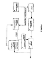
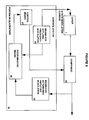
- FIG. 1 shows a schematic block diagram of a known optical transmission system.
- a laser 1 generates an optical output which is fed to an external modulator 2, and subsequently to a narrow band filter 3.
- the laser output is controlled by controlling its temperature, and by controlling the laser current.
- the laser temperature and/or bias current is controlled by means of a feed-back loop.
- In the feed-back loop are an optical to electrical converter, with a low-pass filtering function 4, and a phase sensitive comparator 5, which compares the monitored output of the narrow band filter 3 with a signal representing the dither modulation applied to the laser.
- a dither generator 6 is shown for generating a suitable dither for direct modulation of the laser by modulating the laser current.
- the phase sensitive comparator 5 is operable to detect portions of the monitored signal from the output of the narrow band filter 3 which are in phase with the output of the dither generator 6. An error signal representing the amplitude of the dither appearing at the output of the narrow band filter 3 is fed back to a compensation generator 7 which controls the laser temperature and/or bias current, and thus the laser output frequency. The error signal at the output of the phase sensitive comparator 5 represents the slope of the response of the filter 3 at the laser operating frequency.
- the compensation generator 7 is operable to adjust the temperature and/or bias current of the laser, and thus the frequency of its output, so as to reduce the error signal to zero by moving the laser output frequency to a point on the filter response curve where the slope is zero, i.e. the peak of the response curve.
- frequency stabilisation of a laser uses direct modulation of the injection current to give 50 MHz of frequency modulation on the output, which is then fed through a Fabry-Perot etalon. The injection current is then controlled on the basis of a frequency error signal to lock the laser frequency to the resonant frequency of the etalon. This is shown in Rev. Sci. Instrum. 61(9) September 1990 p2478-2480, "Frequency Stabilisation of a Directly Modulated Laser" by Lee et al.
- Figure 2 shows a similar arrangement to that of figure 1, in which the error signal is fed to a response control means 8 which controls the frequency of the peak of a tuneable filter 23, so as to maintain the peak frequency in alignment with the laser output frequency.
- the AM generated by the laser will produce a steady error in the monitored results.
- the invention aims to provide improved methods and systems.
- control system for controlling the frequency of a laser in an optical transmission system in which the optical output of the laser is passed through an optical component whose output amplitude is dependent on input frequency and input amplitude, the control system comprising:
- This aspect of the invention is based on the insight that although the laser modulation produces both amplitude and frequency modulation, the phase of the FM modulation varies with modulation frequency. In contrast, the generated AM displays negligible phase difference with frequency. Thus across a wide range of frequencies, there is a component of the FM modulation output of the laser which is in quadrature with the "unwanted" AM portion output as a result of the modulation by the dither. By applying modulation to the laser at a frequency in this range, and by detecting only this quadrature component, errors in the detected dither amplitude caused by unwanted AM can be reduced or removed.
- the amount generated by the laser for example is variable both from device to device, and over time, and therefore it is difficult to compensate for it unless it is removed from the detected dither amplitude.
- the laser amplitude modulation is applied by direct modulation of the laser current.
- the component is a narrow band filter.
- An advantageous feature is the provision of means for phase sensitive comparison of the laser amplitude modulation and the detected amplitude modulation. This enables the portion of the detected modulation attributable to the laser modulation to be separated from other portions.
- Another preferred feature is a means for phase shifting a signal representating the laser amplitude modulation or the detected amplitude modulation relative to the other, before input to the phase sensitive comparison. This is a preferred way of obtaining the portion which is substantially in phase quadrature with the laser modulation.
- Another preferred feature is the provision of a dither oscillator operable to output a quadrature signal for input to the phase sensitive comparison means, to achieve the phase shift.
- This has the advantage that the phase shift means can be dispensed with, which can simplify the arrangement.
- Another preferred feature is a means for extracting a selected frequency band, and discriminating the quadrature portion from the selected frequency band. This is particularly useful where the laser modulation covers a range of frequencies.
- the phase sensitive comparison means is likely to achieve better results if it is operating over a limited range of frequencies.
- the frequency selection filter can be located on either of the inputs to the phase sensitive comparison means, or on both inputs.
- Another preferred feature is the provision of means for determining which parts of the input signal are rejected by the component, rather than monitoring the parts which are passed. This can provide improved bandwidth, for the control loop, particularly where the component is a narrow band filter which is arranged to reject more of the signal power than it passes. If the component is a three port filter, the rejected signal can be measured directly.
- the frequency of the laser modulation is determined so as to maximise the detected portion which is in phase quadrature with the laser amplitude modulation. This will have the effect of minimising noise in the control loop. Thus accuracy of detection of the laser modulation is enhanced.
- control means is operable to maintain a constant relationship between the frequency of the laser and the frequency response of the component. This locking of one element to another is a particularly advantageous application of the present invention.
- a control system for controlling the frequency response of an optical component downstream of a laser in an optical transmission system, an output amplitude of the component being dependent on input amplitude and input frequency, the control system comprising:
- a method of controlling the frequency of a laser in an optical transmission system in which the optical output of the laser is passed through an optical component having an output amplitude dependent on input frequency and input amplitude comprising the steps of:
- a method of controlling the frequency response of an optical component downstream of a laser in an optical transmission system, wherein an output amplitude of the component is dependent on input frequency and input amplitude comprising the steps of:
- a method of controlling the frequency response of an optical component downstream of a laser in an optical transmission system comprising the steps of:
- a method of processing a signal downstream of a laser in an optical transmission system, to determine the effect of a frequency modulation applied to the laser output comprising the steps of:
- phase of the FM modulation (relative to the applied modulation current and the resulting amplitude modulation) varies with modulation frequency.
- Semi-conductor lasers generally exhibit negligible phase difference between the applied current modulation and the optical output intensity (amplitude modulation), from DC to high frequencies. This enables them to be used with direct modulation at quite high data rates, and with data patterns with spectral components down to DC.
- the frequency modulation characteristic varies across the information bandwidth.
- the optical frequency increases with drive current, due to the dominant effect of the reduced refractive index resulting from the increased density of holes.
- This carrier effect FM is usually the dominant chirp mechanism in directly modulated lasers.
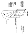
- the thermal effect is represented for four different frequencies.
- the curve shows the path of the tip of the vector as frequency varies. At low frequencies, the phase would be nearly 180°. At high frequencies, the phase would be nearly 90° away from the phase of the carrier effect component. As can be seen, the magnitude of the thermal effect rolls off as frequency increases.
- the total FM output is the vector sum of these two components. This is shown for two of the frequencies. Over a wide range of frequencies, there will be a considerable component of the vector sum in quadrature with the frequency modulation.
- the frequency of modulation is chosen to maximise the magnitude of the quadrature component of the vector sum. This will typically occur at tens or hundreds of kHz depending on the carrier concentration variations, and thermal characteristics within the laser element. These will vary with the particular device structure used. Furthermore, the magnitude of the quadrature signal will vary with lasers of different FM to AM co-efficients. Nevertheless, these effects will not result in any offset error in the control loop as the loop simply stabilises to zero error. By detecting and using only the portion which is in quadrature to the applied modulation, offset errors caused by unwanted AM can be reduced or eliminated.
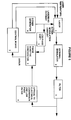
- Figure 4 shows in schematic form a control system according to another embodiment of the invention. It is used for controlling the frequency of a laser 1 which outputs an optical signal which is passed through a component 32.
- the component 32 may be a narrow band filter, or an equivalent such as a fibre grating dispersion compensator with a narrow band frequency response or a narrow band absorption gas cell for example. The steeper the slope or sharper the peak of the response of the component, the more precise is the control of the laser frequency.
- the control system 33 includes means for determining amplitude modulation 35, discriminating means for discriminating a portion which is in quadrature with the applied frequency modulation, and control means 37 for controlling the output frequency of the laser on the basis of the portion in quadrature.
- control means is arranged to drive the quadrature portion towards zero, to lock the laser frequency to a peak on the frequency response of the component. It could be arranged to lock onto a point of known slope, by forcing the quadrature component to a particular non zero value. This is useful for locking to one side of a filter with a flat topped response.
- a means for applying frequency modulation 34 is also shown. This means also feeds the discriminating means, to enable the discriminating means to establish the portion which is in quadrature with the laser modulation.
- the laser modulation could be determined from the laser optical output. However, that would require optical to electrical conversion, which would add to the hardware costs. It would be necessary if in figure 8 component 32 was not co-located with the laser. Provided there is little phase shift between the applied modulation signal and the laser output (which would normally be the case at the preferred frequency range where there is a significant quadrature component), it is more convenient to use the modulation signal applied to the laser to represent the laser modulation.
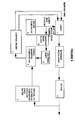
- Figure 5 shows one possible embodiment of the arrangement of figure 4.
- the optical component is shown as a filter 3.
- An external modulator 2 is also shown in the optical path.
- a dither generator 6 applies a modulation to the laser current, which causes the output of the laser to be amplitude and frequency modulated.
- the output frequency of the laser is also adjusted for offset by a temperature control means 7.
- the temperature control means 7 receives an error signal created by low pass filtering of the output of the phase sensitive comparator 5. This error signal is a d.c. value proportional to the amount of amplitude modulation on the output of the filter 3 which is in quadrature with the modulation applied to the laser current.
- the temperature control means 7 is operable to adjust the frequency of the laser 1 so as to reduce the error towards zero, or a predetermined value.
- the detection of the portion which is in quadrature with the applied modulation is achieved by shifting the phase of the modulation by means of the phase shift means 9.
- the output of this phase shift means is applied to the phase sensitive comparator 5.
- the phase shift means can be implemented by a phase locked loop.
- the phase locked loop does a synchronous detection and integrates the result, which is fed back to drive the output to zero. For a single frequency, or a sufficiently narrow band, the output will thus be in quadrature with the input. Because of the integration function, a phase locked loop can produce an output representing an average quadrature of a narrow range of frequencies. For such a range of frequencies, errors owing to different spectral components experiencing slightly different phase shifts will occur. However, the phase lock process can force the sum of such errors to zero, thus producing an averaged quadrature output.
- the frequency modulation on the output of the laser will cause some amplitude modulation as a result of any slope in the response of the filter 3.
- This amount of amplitude modulation will be detected by an optical to electrical conversion means 4, typically a PIN diode, which together with associated electrical amplification stages, will have a significant low pass filtering effect.
- the applied modulation generated by the dither generator 6 should be of relatively low frequency, so as to enable the control loop to be constructed more easily and cheaply.
- the dither may be applied for various different purposes, there may be a range of frequencies included in the dither. Accordingly, as shown in figure 6, a narrow band filter 10 may be included before the dither is fed to the phase shift means 9.
- the selected frequency range should be a range which produces a good quadrature FM component of the applied modulation. This is likely to be in the range between 10 kHz and several 100 kHz. If only a narrow band within this range is selected, the operation of the phase sensitive comparator 5 will be enhanced, because the quadrature condition can be established more accurately.
- FIG. 7 A further alternative is shown in figure 7.
- a quadrature output of the dither generator 6 is fed directly to the phase sensitive comparator 5.
- the dither generator may be an oscillator which produces a sine or square wave dither. In this case it is straightforward to produce quadrature signals by dividing down a higher rate oscillator. Alternatively, the generator may produce a more complex data pattern.
- a miller encoded binary pattern may be appropriate for the modulation, in which case either a signal can be generated in quadrature to this data pattern, with a spectral content over the appropriate range of frequencies, or a 50% duty cycle sine or square wave signal may be generated which is in quadrature to one dominant spectral line of the data pattern. If short length patterns are used, there should be a sufficiently dominant spectral line from which to derive a signal in quadrature.
- Figure 8 shows another embodiment of the invention in schematic form. This differs from the embodiment shown in figure 4 in that a control means 67 is provided to adjust the frequency response of the component 32, rather than the output frequency of the laser 1.
- the dither is still applied to the laser 1 by a means for applying frequency modulation 34.
- the control means 67 is also operable in response to a portion of the determined amplitude modulation which is in quadrature to the applied laser modulation.
- the control means 67 is operable to adjust the frequency response of the component 32 so as to reduce the quadrature portion towards zero. This enables the frequency response of the component to be locked to the output frequency of the laser 1.
- the frequency variation of the laser output will be very small, typically a few GHz.
- the response control means 8 is provided to carry out the function of the control means 67 shown in figure 8. This drives the tuneable filter 23 so as to reduce the quadrature portion, or error signal, output by the phase sensitive comparator 5, towards zero.
- a control means could be implemented by a digital micro processor.
- the temperature compensation generator 7 could be implemented by a digital micro processor with stored programmes to run appropriate control algorithms.
- the phase sensitive comparator 5 could be implemented by conventional analogue circuitry, or in principle, in digital form by a micro processor or a digital signal processor.
- the optical component, or the means for determining amplitude modulation in the signal downstream of the laser need not be near the control system or near the laser.
- a filter remote from the laser may be used to control the laser frequency.
- a tuneable filter located away from the laser may be controlled on the basis of the control system described above using a dither applied to the remote laser. In this case it would be preferable to derive a signal representing the laser amplitude modulation at the remote site, by tapping the input to the remote filter. This could be fed to the quadrature detector after phase shifting as described in relation to figure 5.
Abstract
Description
Claims (23)
- A control system for controlling the frequency of a laser in an optical transmission system in which the optical output of the laser is passed through an optical component whose output amplitude is dependent on input frequency and input amplitude, the control system comprising:means for applying a modulation to the laser which produces frequency modulation and amplitude modulation in an optical output of the laser;means for detecting an amplitude modulation present at the output of the component;means for determining a portion of the detected amplitude modulation which is substantially in phase quadrature with the amplitude modulation in the optical output of the laser; andmeans for controlling the frequency of the laser on the basis of the quadrature portion.
- The control system of claim 1 wherein the frequency modulation is applied by direct modulation of the laser current.
- The control system of claim 1 or 2 wherein the means for determining a portion of the detected amplitude modulation, comprises means for phase sensitive comparison of the laser amplitude modulation and the determined amplitude modulation.
- The control system of claim 3 further comprising means for phase shifting the laser amplitude modulation or the detected amplitude modulation relative to the other, before input to the phase sensitive comparison means.
- The control system of claim 4 wherein the means for applying a frequency modulation comprises a dither oscillator, which is operable to output a quadrature signal for input to the phase sensitive comparison means, to achieve the phase shift.
- The control system of any preceding claim wherein the means for determining a portion of the detected amplitude modulation, comprises means for extracting a selected frequency band and discriminating the portion from the selected frequency band.
- The control system of any preceding claim wherein the means for detecting the amplitude modulation is operable on the basis of a part of the input signal which is rejected by the component.
- The control system of any preceding claim wherein the means for detecting the amplitude modulation is remote from the laser.
- The control system of any preceding claim wherein the frequency of the frequency modulation is determined so as to maximise the quadrature portion.
- The control system of any preceding claim wherein the control means is operable to maintain a constant relationship between the frequency of the laser and the frequency response of the component.
- An optical transmission system comprising a laser, an optical component downstream of the laser, and the control system of claim 1, for controlling the frequency of the laser.
- A control system for controlling the frequency response of an optical component downstream of a laser in an optical transmission system, an output amplitude of the component being dependent on input amplitude and input frequency, the control system comprising:means for applying a modulation to the laser which produces frequency modulation and amplitude modulation in an optical output of the laser;means for detecting an amplitude modulation present at the output of the component;means for determining a portion of the detected amplitude modulation which is substantially in phase quadrature with the amplitude modulation in the optical output of the laser; andmeans for controlling the frequency response of the component on the basis of the quadrature portion.
- The control system of claim 12 wherein the control means is operable to lock a centre frequency of the component frequency response to a centre frequency of the laser.
- The control system of claim 12 or 13, wherein the component performs a narrowband filtering function.
- The control system of any of claims 12 to 14 wherein the component has a dispersion compensation characteristic.
- A method of controlling the frequency of a laser in an optical transmission system in which the optical output of the laser is passed through an optical component having an output amplitude dependent on input frequency and input amplitude, the method comprising the steps of:applying a modulation to the laser which produces frequency modulation and amplitude modulation in an optical output of the laser;detecting an amplitude modulation present at the output of the component;determining a portion of the amplitude modulation which is substantially in phase quadrature with the amplitude modulation in the optical output of the laser; andcontrolling the frequency of the laser on the basis of the quadrature portion.
- A method of transmitting information in an optical transmission system comprising a laser, wherein the laser is controlled according to the method of claim 16.
- A method of controlling the frequency response of an optical component downstream of a laser in an optical transmission system, wherein an output amplitude of the component is dependent on input frequency and input amplitude, the method comprising the steps of:applying a modulation to the laser which produces frequency modulation and amplitude modulation in an optical output of the laser;detecting an amplitude modulation present at the output of the component;determining a portion of the amplitude modulation which is substantially in phase quadrature with the amplitude modulation in the optical output of the laser; andcontrolling the frequency response of the component on the basis of the discriminated portion.
- A method of transmitting information in an optical transmission system comprising a laser and an optical component downstream of the laser, wherein the component is controlled according to the method of claim 18.
- A method of maintaining a constant relationship between the frequency of a laser and the frequency response of an optical component downstream of the laser in an optical transmission system, by controlling the laser by the method of claim 16.
- A method of maintaining a constant relationship between the frequency of a laser and the frequency response of an optical component downstream of the laser in an optical transmission system, by controlling the component according to the method of claim 18.
- A signal processing system for processing a signal downstream of a laser in an optical transmission system, to determine the effect of a frequency modulation applied to the laser output, the processing system comprising: means for determining the amplitude modulation present in the signal and attributable to the applied frequency modulation;and means for determining a portion of the amplitude modulation which is substantially in phase quadrature with the applied frequency modulation.
- A method of processing a signal downstream of a laser in an optical transmission system, to determine the effect of a frequency modulation applied to the laser output, the method comprising the steps of:determining the amplitude modulation present in the signal and attributable to the applied frequency modulation; anddetermining a portion of the amplitude modulation which is substantially in phase quadrature with the applied frequency modulation.
Applications Claiming Priority (2)
| Application Number | Priority Date | Filing Date | Title |
|---|---|---|---|
| US741587 | 1996-10-31 | ||
| US08/741,587 US5777773A (en) | 1996-10-31 | 1996-10-31 | Optical frequency control system and method |
Publications (2)
| Publication Number | Publication Date |
|---|---|
| EP0840468A2 true EP0840468A2 (en) | 1998-05-06 |
| EP0840468A3 EP0840468A3 (en) | 2000-10-11 |
Family
ID=24981334
Family Applications (1)
| Application Number | Title | Priority Date | Filing Date |
|---|---|---|---|
| EP97307859A Withdrawn EP0840468A3 (en) | 1996-10-31 | 1997-10-06 | Optical frequency control system |
Country Status (3)
| Country | Link |
|---|---|
| US (1) | US5777773A (en) |
| EP (1) | EP0840468A3 (en) |
| JP (1) | JP3996683B2 (en) |
Cited By (6)
| Publication number | Priority date | Publication date | Assignee | Title |
|---|---|---|---|---|
| WO2002095990A1 (en) * | 2001-05-25 | 2002-11-28 | International Business Machines Corporation | Wavelengh control using dither modulation and feedback |
| WO2004032294A1 (en) * | 2002-10-04 | 2004-04-15 | Renishaw Plc | Frequency stabilized laser system comprising phase modulation of backscattered light |
| US6970649B2 (en) | 2001-10-30 | 2005-11-29 | International Business Machines Corporation | WDMA free space broadcast technique for optical backplanes and interplanar communications |
| EP1965519A1 (en) * | 2007-02-28 | 2008-09-03 | Yokogawa Electric Corporation | Optical receiver and optical transmitter |
| EP2461498A1 (en) * | 2010-12-02 | 2012-06-06 | Fujitsu Limited | Optical transmitter and optical transmitter unit |
| CN103986052A (en) * | 2014-05-22 | 2014-08-13 | 苏州旭创科技有限公司 | Laser device system, optical transceiver and light source adjusting method of laser device system |
Families Citing this family (75)
| Publication number | Priority date | Publication date | Assignee | Title |
|---|---|---|---|---|
| JPH10163971A (en) * | 1996-11-25 | 1998-06-19 | Fujitsu Ltd | Method, device and system for controlling wavelength of light signal |
| JP3482088B2 (en) * | 1996-12-05 | 2003-12-22 | 松下電器産業株式会社 | Frequency modulation device |
| US5966229A (en) * | 1997-06-18 | 1999-10-12 | At&T Corp. | Free-space optical communications system with open loop transmitter control |
| JP3097618B2 (en) * | 1997-09-30 | 2000-10-10 | 日本電気株式会社 | FM modulator |
| US6081361A (en) * | 1997-10-17 | 2000-06-27 | Lucent Technologies Inc. | Sub-carrier multiplexing in broadband optical networks |
| KR100318922B1 (en) * | 1998-07-30 | 2001-12-29 | 윤종용 | Wavelength stabilization circuit with stabilization monitoring function in optical transmission system using wavelength division multiplexing |
| US6414775B1 (en) * | 1998-12-28 | 2002-07-02 | Tycom (Us) Inc. | Method and apparatus for measuring gain shape in an optical repeater using FM modulation |
| US6714739B1 (en) * | 1999-06-07 | 2004-03-30 | Corvis Corporation | Optical transmission systems and optical receivers and receiving methods for use therein |
| US6879619B1 (en) | 1999-07-27 | 2005-04-12 | Intel Corporation | Method and apparatus for filtering an optical beam |
| US6853654B2 (en) * | 1999-07-27 | 2005-02-08 | Intel Corporation | Tunable external cavity laser |
| US6847661B2 (en) | 1999-09-20 | 2005-01-25 | Iolon, Inc. | Tunable laser with microactuator |
| US6856632B1 (en) | 1999-09-20 | 2005-02-15 | Iolon, Inc. | Widely tunable laser |
| DE10029070A1 (en) | 2000-06-13 | 2002-01-10 | Siemens Ag | Method and arrangement for regulating modulated lasers |
| US7120176B2 (en) * | 2000-07-27 | 2006-10-10 | Intel Corporation | Wavelength reference apparatus and method |
| WO2002078137A1 (en) * | 2001-03-21 | 2002-10-03 | Intel Corporation | Laser apparatus with active thermal tuning of external cavity |
| US6816516B2 (en) | 2001-03-21 | 2004-11-09 | Intel Corporation | Error signal generation system |
| US6658031B2 (en) * | 2001-07-06 | 2003-12-02 | Intel Corporation | Laser apparatus with active thermal tuning of external cavity |
| US7848660B1 (en) * | 2001-06-20 | 2010-12-07 | Cisco Technology, Inc. | VSB transmitter using locked filter |
| US7031619B2 (en) * | 2001-06-26 | 2006-04-18 | International Business Machines Corporation | Method and system for dispersion control of electromagnetic signals in communication networks |
| US6822979B2 (en) | 2001-07-06 | 2004-11-23 | Intel Corporation | External cavity laser with continuous tuning of grid generator |
| US6788724B2 (en) * | 2001-07-06 | 2004-09-07 | Intel Corporation | Hermetically sealed external cavity laser system and method |
| US6631146B2 (en) * | 2001-07-06 | 2003-10-07 | Intel Corporation | Tunable laser control system |
| US6804278B2 (en) | 2001-07-06 | 2004-10-12 | Intel Corporation | Evaluation and adjustment of laser losses according to voltage across gain medium |
| US6901088B2 (en) | 2001-07-06 | 2005-05-31 | Intel Corporation | External cavity laser apparatus with orthogonal tuning of laser wavelength and cavity optical pathlength |
| US20030058509A1 (en) * | 2001-09-24 | 2003-03-27 | Ditech Communications Corporation | Optical vestigial sideband (VSB) transmission |
| US7190904B2 (en) * | 2001-09-26 | 2007-03-13 | International Business Machines Corporation | Wavelength modulation for optical based switching and routing |
| US7444079B2 (en) * | 2001-10-12 | 2008-10-28 | International Business Machines Corporation | Optical power control monitor for multiple wavelength fiber-optic networks |
| US7230959B2 (en) * | 2002-02-22 | 2007-06-12 | Intel Corporation | Tunable laser with magnetically coupled filter |
| US6763047B2 (en) * | 2002-06-15 | 2004-07-13 | Intel Corporation | External cavity laser apparatus and methods |
| US6845121B2 (en) * | 2002-06-15 | 2005-01-18 | Intel Corporation | Optical isolator apparatus and methods |
| US7263291B2 (en) * | 2002-07-09 | 2007-08-28 | Azna Llc | Wavelength division multiplexing source using multifunctional filters |
| US7663762B2 (en) | 2002-07-09 | 2010-02-16 | Finisar Corporation | High-speed transmission system comprising a coupled multi-cavity optical discriminator |
| US6963685B2 (en) * | 2002-07-09 | 2005-11-08 | Daniel Mahgerefteh | Power source for a dispersion compensation fiber optic system |
| US7054538B2 (en) * | 2002-10-04 | 2006-05-30 | Azna Llc | Flat dispersion frequency discriminator (FDFD) |
| US7742542B2 (en) * | 2002-11-06 | 2010-06-22 | Finisar Corporation | Phase correlated quadrature amplitude modulation |
| US7280721B2 (en) * | 2002-11-06 | 2007-10-09 | Azna Llc | Multi-ring resonator implementation of optical spectrum reshaper for chirp managed laser technology |
| US7564889B2 (en) * | 2002-11-06 | 2009-07-21 | Finisar Corporation | Adiabatically frequency modulated source |
| US7505694B2 (en) * | 2002-11-06 | 2009-03-17 | Finisar Corporation | Thermal chirp compensation systems for a chirp managed directly modulated laser (CML™) data link |
| US7406266B2 (en) * | 2002-11-06 | 2008-07-29 | Finisar Corporation | Flat-topped chirp induced by optical filter edge |
| US7558488B2 (en) * | 2002-11-06 | 2009-07-07 | Finisar Corporation | Reach extension by using external Bragg grating for spectral filtering |
| US7536113B2 (en) * | 2002-11-06 | 2009-05-19 | Finisar Corporation | Chirp managed directly modulated laser with bandwidth limiting optical spectrum reshaper |
| US7542683B2 (en) | 2002-12-03 | 2009-06-02 | Finisar Corporation | Chirp Managed Laser (CML) transmitter |
| US7809280B2 (en) * | 2002-12-03 | 2010-10-05 | Finisar Corporation | Chirp-managed, electroabsorption-modulated laser |
| US7925172B2 (en) * | 2002-12-03 | 2011-04-12 | Finisar Corporation | High power, low distortion directly modulated laser transmitter |
| US7480464B2 (en) * | 2002-12-03 | 2009-01-20 | Finisar Corporation | Widely tunable, dispersion tolerant transmitter |
| US7609977B2 (en) * | 2002-12-03 | 2009-10-27 | Finisar Corporation | Optical transmission using semiconductor optical amplifier (SOA) |
| US7813648B2 (en) * | 2002-12-03 | 2010-10-12 | Finisar Corporation | Method and apparatus for compensating for fiber nonlinearity in a transmission system |
| US7474859B2 (en) * | 2002-12-03 | 2009-01-06 | Finisar Corporation | Versatile compact transmitter for generation of advanced modulation formats |
| US7907648B2 (en) * | 2002-12-03 | 2011-03-15 | Finisar Corporation | Optical FM source based on intra-cavity phase and amplitude modulation in lasers |
| US7613401B2 (en) * | 2002-12-03 | 2009-11-03 | Finisar Corporation | Optical FM source based on intra-cavity phase and amplitude modulation in lasers |
| US7860404B2 (en) * | 2002-12-03 | 2010-12-28 | Finisar Corporation | Optical FM source based on intra-cavity phase and amplitude modulation in lasers |
| US8792531B2 (en) | 2003-02-25 | 2014-07-29 | Finisar Corporation | Optical beam steering for tunable laser applications |
| US7630425B2 (en) * | 2003-02-25 | 2009-12-08 | Finisar Corporation | Optical beam steering for tunable laser applications |
| GB0308951D0 (en) * | 2003-04-17 | 2003-05-28 | Azea Networks Ltd | Top-flat spectrum data format for Nx40 Gbit/s WDM transmission with 0.8 bit/s/Hz spectral efficiency |
| US7639955B2 (en) * | 2004-09-02 | 2009-12-29 | Finisar Corporation | Method and apparatus for transmitting a signal using a chirp managed laser (CML) and an optical spectrum reshaper (OSR) before an optical receiver |
| US20070012860A1 (en) * | 2005-05-05 | 2007-01-18 | Daniel Mahgerefteh | Optical source with ultra-low relative intensity noise (RIN) |
| US7697186B2 (en) * | 2006-10-24 | 2010-04-13 | Finisar Corporation | Spectral response modification via spatial filtering with optical fiber |
| WO2008080171A1 (en) * | 2006-12-22 | 2008-07-03 | Finisar Corporation | Optical transmitter having a widely tunable directly modulated laser and periodic optical spectrum reshaping element |
| US7941057B2 (en) * | 2006-12-28 | 2011-05-10 | Finisar Corporation | Integral phase rule for reducing dispersion errors in an adiabatically chirped amplitude modulated signal |
| US8131157B2 (en) * | 2007-01-22 | 2012-03-06 | Finisar Corporation | Method and apparatus for generating signals with increased dispersion tolerance using a directly modulated laser transmitter |
| EP2111678B1 (en) * | 2007-02-02 | 2015-04-08 | Finisar Corporation | Temperature stabilizing packaging for optoelectronic components in a transmitter module |
| US8027593B2 (en) | 2007-02-08 | 2011-09-27 | Finisar Corporation | Slow chirp compensation for enhanced signal bandwidth and transmission performances in directly modulated lasers |
| US7991291B2 (en) | 2007-02-08 | 2011-08-02 | Finisar Corporation | WDM PON based on DML |
| US7697847B2 (en) * | 2007-04-02 | 2010-04-13 | Finisar Corporation | Dispersion compensator for frequency reshaped optical signals |
| US7991297B2 (en) * | 2007-04-06 | 2011-08-02 | Finisar Corporation | Chirped laser with passive filter element for differential phase shift keying generation |
| US8204386B2 (en) * | 2007-04-06 | 2012-06-19 | Finisar Corporation | Chirped laser with passive filter element for differential phase shift keying generation |
| US7760777B2 (en) * | 2007-04-13 | 2010-07-20 | Finisar Corporation | DBR laser with improved thermal tuning efficiency |
| US7778295B2 (en) * | 2007-05-14 | 2010-08-17 | Finisar Corporation | DBR laser with improved thermal tuning efficiency |
| US8160455B2 (en) * | 2008-01-22 | 2012-04-17 | Finisar Corporation | Method and apparatus for generating signals with increased dispersion tolerance using a directly modulated laser transmitter |
| WO2009114738A2 (en) | 2008-03-12 | 2009-09-17 | Hypres, Inc. | Digital radio-frequency tranceiver system and method |
| US7869473B2 (en) * | 2008-03-21 | 2011-01-11 | Finisar Corporation | Directly modulated laser with isolated modulated gain electrode for improved frequency modulation |
| US8260150B2 (en) * | 2008-04-25 | 2012-09-04 | Finisar Corporation | Passive wave division multiplexed transmitter having a directly modulated laser array |
| JP2010011098A (en) * | 2008-06-27 | 2010-01-14 | Fujitsu Ltd | Optical transmission device |
| US8199785B2 (en) | 2009-06-30 | 2012-06-12 | Finisar Corporation | Thermal chirp compensation in a chirp managed laser |
| US11374380B2 (en) * | 2017-12-15 | 2022-06-28 | Horiba, Ltd. | Semiconductor laser |
Citations (2)
| Publication number | Priority date | Publication date | Assignee | Title |
|---|---|---|---|---|
| US5204640A (en) * | 1992-02-10 | 1993-04-20 | California Institute Of Technology | Widely tunable oscillator stabilization using analog fiber optic delay line |
| US5510922A (en) * | 1994-06-28 | 1996-04-23 | Fujitsu Limited | Optical frequency stabilizer and optical frequency selector |
Family Cites Families (2)
| Publication number | Priority date | Publication date | Assignee | Title |
|---|---|---|---|---|
| US5347392A (en) * | 1992-02-26 | 1994-09-13 | The United States Of America As Represented By The Administrator Of The National Aeronautics And Space Administration | Electric-optic resonant phase modulator |
| US5373385A (en) * | 1993-11-12 | 1994-12-13 | At&T Corp. | Method and apparatus for reduction of optical communication system impairments |
-
1996
- 1996-10-31 US US08/741,587 patent/US5777773A/en not_active Expired - Lifetime
-
1997
- 1997-10-06 EP EP97307859A patent/EP0840468A3/en not_active Withdrawn
- 1997-10-27 JP JP31146997A patent/JP3996683B2/en not_active Expired - Fee Related
Patent Citations (2)
| Publication number | Priority date | Publication date | Assignee | Title |
|---|---|---|---|---|
| US5204640A (en) * | 1992-02-10 | 1993-04-20 | California Institute Of Technology | Widely tunable oscillator stabilization using analog fiber optic delay line |
| US5510922A (en) * | 1994-06-28 | 1996-04-23 | Fujitsu Limited | Optical frequency stabilizer and optical frequency selector |
Cited By (10)
| Publication number | Priority date | Publication date | Assignee | Title |
|---|---|---|---|---|
| WO2002095990A1 (en) * | 2001-05-25 | 2002-11-28 | International Business Machines Corporation | Wavelengh control using dither modulation and feedback |
| US7061944B2 (en) | 2001-05-25 | 2006-06-13 | International Business Machines Corporation | Apparatus and method for wavelength-locked loops for systems and applications employing electromagnetic signals |
| US6970649B2 (en) | 2001-10-30 | 2005-11-29 | International Business Machines Corporation | WDMA free space broadcast technique for optical backplanes and interplanar communications |
| WO2004032294A1 (en) * | 2002-10-04 | 2004-04-15 | Renishaw Plc | Frequency stabilized laser system comprising phase modulation of backscattered light |
| CN100464471C (en) * | 2002-10-04 | 2009-02-25 | 瑞尼斯豪公司 | Frequency stabilized laser system comprising phase modulation of backscattered light |
| EP1965519A1 (en) * | 2007-02-28 | 2008-09-03 | Yokogawa Electric Corporation | Optical receiver and optical transmitter |
| EP2461498A1 (en) * | 2010-12-02 | 2012-06-06 | Fujitsu Limited | Optical transmitter and optical transmitter unit |
| US8526828B2 (en) | 2010-12-02 | 2013-09-03 | Fujitsu Limited | Optical transmitter and optical transmitter unit |
| CN103986052A (en) * | 2014-05-22 | 2014-08-13 | 苏州旭创科技有限公司 | Laser device system, optical transceiver and light source adjusting method of laser device system |
| CN103986052B (en) * | 2014-05-22 | 2017-05-17 | 苏州旭创科技有限公司 | Laser device system, optical transceiver and light source adjusting method of laser device system |
Also Published As
| Publication number | Publication date |
|---|---|
| US5777773A (en) | 1998-07-07 |
| JPH10190106A (en) | 1998-07-21 |
| EP0840468A3 (en) | 2000-10-11 |
| JP3996683B2 (en) | 2007-10-24 |
Similar Documents
| Publication | Publication Date | Title |
|---|---|---|
| US5777773A (en) | Optical frequency control system and method | |
| US7023887B2 (en) | Method and system for controlling optical wavelength based on optical frequency pulling | |
| US7027743B1 (en) | System and method for optical heterodyne detection of an optical signal including optical pre-selection that is adjusted to accurately track a local oscillator signal | |
| US5390017A (en) | Optical network analyzer for measuring the amplitude characteristics and group delay time dispersion characteristics of an optical circuit device | |
| US6493131B1 (en) | Wavelength-locking of optical sources | |
| JP4608512B2 (en) | Frequency stabilized light source | |
| JP2002033548A (en) | Method and apparatus for driving mode-locked semiconductor laser | |
| JP3996815B2 (en) | Optical frequency synthesizer | |
| CN210693007U (en) | System for inhibiting single-frequency phase noise of laser | |
| US6724786B2 (en) | Variable optical attenuator using wavelength locked loop tuning | |
| CN110829167A (en) | Method and system for inhibiting single-frequency phase noise of laser | |
| JPH0595331A (en) | Light transmitting apparatus and modulating method thereof | |
| GB2250394A (en) | Optical frequency synthesis | |
| JP2006337832A (en) | Method and device for generating optical frequency comb | |
| US6552624B2 (en) | Method for controlling the operating range of a modulator, and an associated drive unit | |
| JP2501484B2 (en) | Wavelength stabilization laser device | |
| JP2022168693A (en) | Optical comb generator control device | |
| EP4123257A1 (en) | Phase tuning and phase stabilization of an interferometer | |
| JP3269461B2 (en) | Multi-wavelength light source device | |
| JP3207211B2 (en) | Measurement and control device for optical frequency shift of semiconductor laser | |
| KR0134004B1 (en) | Apparatus for bias control of mach zehnder interference and fabry-perot filter | |
| JPH03109787A (en) | Apparatus for stabilizing frequency of semiconductor array laser | |
| JP2977919B2 (en) | Measuring and controlling device for optical frequency shift of semiconductor laser | |
| US5017880A (en) | Varying operational frequency control circuit apparatus with noise minimizing feature | |
| JPH0964486A (en) | Laser light source device |
Legal Events
| Date | Code | Title | Description |
|---|---|---|---|
| PUAI | Public reference made under article 153(3) epc to a published international application that has entered the european phase |
Free format text: ORIGINAL CODE: 0009012 |
|
| AK | Designated contracting states |
Kind code of ref document: A2 Designated state(s): DE FR GB IT NL SE |
|
| RAP3 | Party data changed (applicant data changed or rights of an application transferred) |
Owner name: NORTEL NETWORKS CORPORATION |
|
| PUAL | Search report despatched |
Free format text: ORIGINAL CODE: 0009013 |
|
| RAP1 | Party data changed (applicant data changed or rights of an application transferred) |
Owner name: NORTEL NETWORKS LIMITED |
|
| AK | Designated contracting states |
Kind code of ref document: A3 Designated state(s): AT BE CH DE DK ES FI FR GB GR IE IT LI LU MC NL PT SE |
|
| RIC1 | Information provided on ipc code assigned before grant |
Free format text: 7H 04B 10/155 A, 7H 04B 10/145 B |
|
| 17P | Request for examination filed |
Effective date: 20010411 |
|
| AKX | Designation fees paid |
Free format text: DE FR GB IT NL SE |
|
| RAP1 | Party data changed (applicant data changed or rights of an application transferred) |
Owner name: NORTEL NETWORKS LIMITED |
|
| STAA | Information on the status of an ep patent application or granted ep patent |
Free format text: STATUS: THE APPLICATION HAS BEEN WITHDRAWN |
|
| 18W | Application withdrawn |
Effective date: 20041021 |