EP0842641B1 - Medical waste disposal container - Google Patents
Medical waste disposal container Download PDFInfo
- Publication number
- EP0842641B1 EP0842641B1 EP97119980A EP97119980A EP0842641B1 EP 0842641 B1 EP0842641 B1 EP 0842641B1 EP 97119980 A EP97119980 A EP 97119980A EP 97119980 A EP97119980 A EP 97119980A EP 0842641 B1 EP0842641 B1 EP 0842641B1
- Authority
- EP
- European Patent Office
- Prior art keywords
- tumbler
- housing enclosure
- disposal
- medical waste
- container
- Prior art date
- Legal status (The legal status is an assumption and is not a legal conclusion. Google has not performed a legal analysis and makes no representation as to the accuracy of the status listed.)
- Expired - Lifetime
Links
Images


Classifications
-
- B—PERFORMING OPERATIONS; TRANSPORTING
- B65—CONVEYING; PACKING; STORING; HANDLING THIN OR FILAMENTARY MATERIAL
- B65F—GATHERING OR REMOVAL OF DOMESTIC OR LIKE REFUSE
- B65F1/00—Refuse receptacles; Accessories therefor
- B65F1/10—Refuse receptacles; Accessories therefor with refuse filling means, e.g. air-locks
-
- A—HUMAN NECESSITIES
- A61—MEDICAL OR VETERINARY SCIENCE; HYGIENE
- A61B—DIAGNOSIS; SURGERY; IDENTIFICATION
- A61B50/00—Containers, covers, furniture or holders specially adapted for surgical or diagnostic appliances or instruments, e.g. sterile covers
- A61B50/30—Containers specially adapted for packaging, protecting, dispensing, collecting or disposing of surgical or diagnostic appliances or instruments
- A61B50/36—Containers specially adapted for packaging, protecting, dispensing, collecting or disposing of surgical or diagnostic appliances or instruments for collecting or disposing of used articles
- A61B50/362—Containers specially adapted for packaging, protecting, dispensing, collecting or disposing of surgical or diagnostic appliances or instruments for collecting or disposing of used articles for sharps
-
- A—HUMAN NECESSITIES
- A61—MEDICAL OR VETERINARY SCIENCE; HYGIENE
- A61B—DIAGNOSIS; SURGERY; IDENTIFICATION
- A61B50/00—Containers, covers, furniture or holders specially adapted for surgical or diagnostic appliances or instruments, e.g. sterile covers
- A61B2050/005—Containers, covers, furniture or holders specially adapted for surgical or diagnostic appliances or instruments, e.g. sterile covers with a lid or cover
- A61B2050/0051—Containers, covers, furniture or holders specially adapted for surgical or diagnostic appliances or instruments, e.g. sterile covers with a lid or cover closable by rotation
- A61B2050/0056—Containers, covers, furniture or holders specially adapted for surgical or diagnostic appliances or instruments, e.g. sterile covers with a lid or cover closable by rotation about a lateral axis in the lid plane
-
- A—HUMAN NECESSITIES
- A61—MEDICAL OR VETERINARY SCIENCE; HYGIENE
- A61B—DIAGNOSIS; SURGERY; IDENTIFICATION
- A61B50/00—Containers, covers, furniture or holders specially adapted for surgical or diagnostic appliances or instruments, e.g. sterile covers
- A61B2050/005—Containers, covers, furniture or holders specially adapted for surgical or diagnostic appliances or instruments, e.g. sterile covers with a lid or cover
- A61B2050/0067—Types of closures or fasteners
- A61B2050/0083—Snap connection
Definitions
- the present invention relates generally to the disposal of contaminated items and, in particular, to a disposal apparatus for use in a hospital or similar environment where contaminated items must be collected and disposed without creating a hazard for patients or hospital personnel.
- the barrier on the outer enclosure is a shelf and a cowl combination which together define an opening.
- the barrier makes it difficult for an adult human hand to pass through the opening. This system is not entirely effective, however, in preventing access to sharps within the container.
- U.S. Patent No. 5,387,735 issued to Ponsi et al. from which the opening clause of claim 1 starts.
- This patent also includes a barrier and pivotal closure disposed near an opening of a container body.
- the pivotal closure is shaped to include retention pocket which prevents sharps from being dispensed through the opening from the interior of the container when the container is upright.
- the retention pocket is required to reduce the possibility of injury by helping to prevent ejection of sharps out of the container.
- locking tabs which are integral with the pivotal closure and provide for locking the closure in a closed position before disposal of a container which is filled.
- the disposal system of Ponsi et al. however, like the sharps container of Hanifl, also suffers from a somewhat limited protection against access to sharps within the container. Consequently, improper reuse and possible contamination can ensue.
- the medical waste disposal container according to the present invention overcomes the limitations, difficulties, and shortcomings of these prior art devices by providing a safe way for health care workers to dispose of used or contaminated sharps, such as hypodermic needles, intravenous needles, razors, and scalpel blades, as well as other contaminated products.
- the apparatus includes a hollow disposal container and a housing enclosure which is engageable with and covers the container.
- An upper opening is provided at the top of the housing enclosure for permitting access to its interior.
- the housing enclosure is provided with a tumbler which prevents access to the interior of the housing enclosure when a contaminated product is being deposited into the interior of the disposal container.
- the tumbler upon dropping waste into the opening of the housing enclosure, the tumbler is rotated to simultaneously close off the upper opening in the housing enclosure and open a lower opening to the disposal container to permit the waste to drop into the disposal container.
- the tumbler which is weighted, returns to its original position.
- the tumbler is configured so that it is blocked by the medical waste in the disposal container and will not return to the open position but remains rotated in a closed position.
- a tumbler having an angled tip portion is provided which forms a lower passage to permit waste to pass while simultaneously blocking accessibility beyond the interior of the housing enclosure without the need to fully rotate the tumbler to a closed position.
- the back of the housing enclosure has a portion with a squared or sloping contour which helps to prevent sharps from returning through or being ejected from the opening of the container.
- the housing enclosure of an embodiment of the present invention also includes a lid having a lock for securely closing the medical waste disposal system for final disposal.
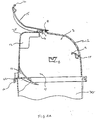
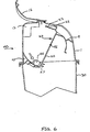
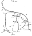
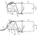
- Fig. 1 shows a medical waste disposal system 40 outside the scope of the present invention having a hollow housing enclosure 1 and a hollow disposal container 30 which are attached to each other and having a tumbler or pivotal closure 20 pivotally mounted within housing enclosure 1.
- Housing enclosure 1 is provided with a flap or ramp 10 which extends beneath housing enclosure 1 and into disposal container 30 as shown.
- nbs 13 which reinforce the upper back interior portion of housing enclosure 1 and extend parallel to the cross-sectional plane of Fig. 1.
- Tumbler 20 forms a barrier which restricts access by a user both to the interior of housing enclosure 1 and to the interior of disposal container 30 when tumbler 20 is rotated to dispose of a sharp 42 (see FIG. 4A) deposited in housing enclosure 1.
- Tumbler 20 is pivotally mounted inside housing enclosure 1 by pivot pins 26 engaged in pivot brackets 8 formed on the interior of housing enclosure 1. By this construction, tumbler 20 can pivot about a pivot axis extending through opposite pivot pins 26.
- tumbler refers to a pivoting mechanism which (a) closes and opens access to both the interior of housing enclosure 1 and the interior of disposal container 30, and (b) transfers sharp 42 from one position to another. At least one source of the name is the tumbling action which sharp 42 undergoes as it is transferred from outside housing enclosure 1 to the interior of disposal container 30 along tumbler 20; specifically, sharp 42 may somersault as it falls downward.
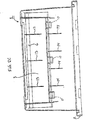
- Figs. 2A, 2B, 2C, 2D, 2E, and 2F respectively show a partial cross-sectional side view, a sectional planar view, a front planar view, a side view, a top planar view, and a bottom planar view of housing enclosure 1 of medical waste disposal system 40 shown in Fig. 1 with flap 10 removed for clarity in Figs. 2B-2F.
- Ribs 13 are substantially flat projections of finite thickness which, as discussed above, extend parallel with the cross-sectional plane of Fig. 1, and are shown in detail in Figs. 2A-2F. Typically three ribs 13 are used.
- ribs 13 may also be used to prevent over-rotation of tumbler 20 as shown in Figs. 9A and 9B and discussed in detail below.
- reinforcing projections 6 are also shown in Figs. 2A-2F which are provided to increase the rigidity of housing enclosure 1. Additional reinforcement may also be provided in other areas of housing enclosure 1 by adding ribs 14 which are substantially flat projections of finite thickness as shown in Figs. 2C, 2D, 2E, and 2F.
- disposal container 30 is preferably snap-fitted onto housing enclosure 1 in a conventional fashion as shown by lip 32 of disposal container 30 which is engaged by snap-tab 12 of housing enclosure 1.
- Other attachment mechanisms can be used as desired.
- Upper opening 3 is provided in housing enclosure 1 to permit access to the interior of housing enclosure 1 for depositing sharps or other medical waste products to be disposed.
- Lower opening 4 is provided by the hollow of housing enclosure 1 to permit the sharps or medical waste products deposited to pass to disposal container 30.
- Pivot brackets 8 and flap 10 are attached to the interior of housing enclosure 1 which, depending on manufacturing capabilities and the desire of the user, may be formed integrally (i.e., in one piece) or may be separately constructed and then attached to housing enclosure 1.
- Fig. 3 shows in greater detail a cross-sectional side view of tumbler 20 of medical waste disposal system 40 shown in Fig. 1.
- Tumbler 20 includes an upper portion 23 and a curved lower portion 24 which are dimensioned so that together they extend across upper opening 3 of housing enclosure 1 when mounted and rotated in housing enclosure 1.
- Upper portion 23 and curved lower portion 24 may be used to prevent over-rotation of tumbler 20 as discussed in detail below.
- Curved lower portion 24 has curvature sufficient to rotate within the curvature of housing enclosure 1 and also includes a flange 25 for engaging lower stop 9 of housing enclosure 1 shown in Fig. 2A.
- upper portion 23 also includes a grip 22 to allow the user to readily manipulate tumbler 20 when using disposal system 40.
- Grip 22 may be provided in a variety of configurations and is not necessarily confined within the interior of housing enclosure 1. As shown, for example, in Fig. 11, grip 22 may extend outside of and may be configured to engage a portion of the wall of housing enclosure 1.
- a chute 28 is defined between a pair of opposed side walls 19 in tumbler 20 to ensure that any sharps to be disposed do not become wedged during rotation of tumbler 20.
- Medical waste disposal system 40 operates to allow waste to be loaded into upper opening 3 of housing enclosure 1, where it causes tumbler 20 to rotate. As tumbler 20 rotates, it simultaneously closes off upper opening 3 and opens lower opening 4 in housing enclosure 1 to allow the waste to drop into disposal container 30. After the waste has dropped, tumbler 20 is weighted to return to its original position. Thus, by permitting only upper opening 3 or lower opening 4 to be substantially opened at any given point in time, tumbler 20 prevents the hand of a user from following the same path into disposal container 30. Tumbler 20 can lock to prevent access to the interior of housing enclosure 1 and disposal container 30 once disposal container 30 is filled. To further secure disposal system 40, lid 15 can be closed as described in greater detail below.
- a used sharp 42 may be passed through upper opening 3 of housing enclosure 1 and placed on an outer portion 29 of tumbler 20, typically one at a time.
- Counterweight 27 is provided on tumbler 20 for adjusting the center of gravity of tumbler 20 to bias it in the inclined and open orientation shown in Fig. 4A prior to loading.
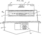
- Fig. 4B illustrates the use of various instructions, directions, and signs to provide information to the user.
- lid 15 may have instructions 66 on its inner surface advising the user, for example, to "CLOSE AND SNAP LID BEFORE REPLACING CONTAINER.”
- Upper portion 23 of tumbler 20 may have directions 67 advising the user, for example, to "DROP SHARP HORIZONTALLY IN OPENING,” "LIFT TABS TO ASSIST DEPOSIT,” or both.
- Directions 67 may include arrows pointing the user in an appropriate direction.
- disposal container 30 may have a sign 68 on its outer surface illustrating a recommended fill line and providing the user with cautionary information.
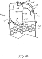
- any sharps 42 which are deposited slide away from upper portion 23 of tumbler 20 toward the back of housing enclosure 1. If sufficiently massive, the weight of any sharps 42 which are deposited causes tumbler 20 to pivot as shown in the sequence of Figs. 6 and 7, thereby dropping sharps 42 within disposal container 30.
- Counterweight 27 may be adjusted so that rotation occurs upon the placement of a predetermined weight of sharps on tumbler 20. If sharp 42 does not have sufficient weight to overbalance the counterbalancing of counterweight 27, the user can manually cause sharp 42 to fall within disposal container 30 in exactly the same fashion. This is accomplished by grasping and moving grip 22 to pivot tumbler 20 upwardly in relation to grip 22, to cause sharp 42 to fall into disposal container 30.
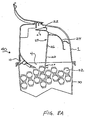
- tumbler 20 When disposal container 30 reaches full capacity, tumbler 20 is configured so that it will not return to the open position but remains rotated in a closed position. As shown in Fig. 8A, when disposal container 30 is filled, tumbler 20, which is rotated to close upper opening 3, is blocked from rotation in the opposite direction by the last sharp deposited. In this blocked orientation in the closed position, tumbler 20 does not permit any more waste to be deposited because upper opening 3 remains closed.
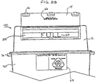
- An indicator 60 is also provided to easily and quickly inform a user by a cursory inspection of disposal system 40 that disposal container 30 is filled and that the user should not attempt to deposit any more waste. As shown in Fig. 8B, indicator 60 may comprise printing or stamping the word "FULL" into the area of lower portion 24 of tumbler 20 which appears in plain view of a user in upper opening 3 when tumbler 20 is blocked in the closed position.
- a user can further secure disposal system 40 by closing and locking lid 15 to housing enclosure 1.
- lid 15 which is shown in the open position, is pivotally mounted to housing enclosure 1 by hinge 18 and has locking tabs 16 which are configured to engage locking aperture 17 of housing enclosure 1.
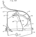
- Fig. 8C upon rotating lid 15 closed and pressing on locking tabs 16 so that they engage locking aperture 17 in housing enclosure 1, a user may securely close disposal container 30 by covering upper opening 3.
- an indicator 61 may be provided on lid 15 which may comprise printing or stamping the word "FULL" into the outer surface of lid 15 to easily and quickly inform a user by a cursory inspection the condition of disposal system 40.
- handles 31 may be provided on disposal container 30 to facilitate transporting of disposal system 40.
- tumbler 20 includes upper portion 23 and curved lower portion 24 which can include a variety of mechanisms to prevent over-rotation of tumbler 20.
- Fig. 9A Shown in Fig. 9A is the use of rib 13 as a stop for upper portion 23 which may be used in conjunction with or as an alternative for a stop provided by flange 25 of curved lower portion 24 which engages lower stop 9 of housing enclosure 1.
- rib 13 may be configured in a variety of shapes to provide a stop for upper portion 23. Rib 13 may also be extended as shown in Figs. 12-16. As shown in Fig.
- upper portion 23 may be configured to include web 47 which rests upon housing stop 48 provided on housing enclosure 1 when tumbler 20 is in the fully open position shown in Fig. 10D. As shown in Fig. 10A, upper portion 23 may also be configured so that it engages an upper stop 7 in housing enclosure 1 and may be provided as a replacement for or an additional structure to be used with rib 13 for preventing over-rotation of tumbler 20. As shown in Fig. 10A, upper stop 7 is constructed by configuring and positioning reinforcing projections 6 so that they engage upper portion 23 thereby impeding movement of upper portion 23 to prevent over-rotation of tumbler 20.
- FIGs. 9B and 10D-10K show alternative housing enclosures 1 which incorporate a stop mechanism provided by a scoop 2 which is a curved projection on the inner surface of housing enclosure 1.
- Scoop 2 has a curved profile which permits lower portion 24 to move freely but prevents over-rotation of lower portion 24 upon rotating tumbler 20.
- scoop 2 may be added as a back-up stop mechanism to be used in conjunction with an upper stop mechanism such as rib 13 or may be used as the sole stop mechanism for tumbler 20 as shown in Figs. 10D-10K.
- the stop mechanism provided by scoop 2 is particularly well-suited for use with tumbler 20 shown in Fig. 9B having an angled tip portion 21 which is discussed in detail below with respect to Figs. 10D-10K.
- ribs 13 are not required and may be eliminated from housing enclosure 1 as both a reinforcing structure and a stop mechanism provided that the shape and thickness of housing enclosure 1 are adjusted to accommodate the in-service stresses to which disposal system 40 will be subjected and an alternative stop mechanism is provided for tumbler 20.
- An exemplary system without ribs 13 is shown in Fig. 10D which has alternative housing enclosure 1 with scoop 2 used in conjunction with tumbler 20 having angled tip portion 21.
- a used sharp 42 is passed through upper opening 3 of housing enclosure 1 and placed onto tumbler 20 when lid 15 and tumbler 20 are in the open position.
- the weight of any sharps 42 which are deposited causes tumbler 20 to pivot thereby dropping sharps 42 through lower opening 4 in housing enclosure 1 as shown sequentially in Figs. 10E-10K.
- any sharps 42 which are deposited slide along the first straight portion 70 toward angled tip portion 21 of tumbler 20 and rest in crux 41 formed in tumbler 20 between first straight portion 70 and angled tip portion 21.
- lid or cover 15 is separate from and independent of tumbler 20.
- This provides the distinct advantage to the user that, in the event of a malfunction of tumbler 20, where tumbler 20 may be jammed in the open or partially open position, the user can simply close lid 15 and lock lid 15 shut, independent of the tumbler position.
- This differs from other disposal systems which rely on movement of a pivotal closure or tumbler to accomplish both the independent and separate functions of (1) disposing of sharps 42, and (2) locking the housing enclosure and container shut when disposal is complete.
- the construction shown allows the user to securely shut and lock waste disposal system 40 at any time, thereby preventing a potentially dangerous situation.
- the user is doubly protected from inadvertently extending fingers within disposal container 30.
- Disposal system 40 also prevents sharps 42 from passing or being ejected back through upper opening 3 of disposal container 30.
- sharps 42 By shaping the back interior portion of housing enclosure 1 with a squared or sloping contour, sharps 42 which are loaded into housing enclosure 1 are deflected away from upper opening 3.
- the present invention eliminates the need for a pivotal closure having a retention pocket to deflect and maintain sharps 42 within disposal container 30.
- Fig. 1 shows an exemplary housing enclosure 1 having a squared contour portion 35.
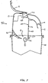
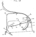
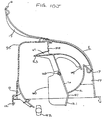
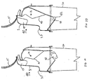
- Fig. 11 which shows an embodiment of the invention, shows an exemplary housing enclosure 1 having a sloped contour portion 36 extending downwardly toward upper opening 3.
- sloped contoured portion 36 is formed in a parabolic shape; this shape further enhances the downward deflection of sharps 42.
- the back portion of housing enclosure 1 may also be configured to have an "S"-shaped portion 37 as shown in Figs. 17-20.
- FIG. 11 Also shown in Fig. 11 are two additional features which help to prevent sharps 42 from being ejected from housing enclosure 1, namely, end flap 44 and memory hinge 45 which are incorporated into tumbler 20.
- end flap 44 By providing tumbler 20 with a memory hinge 45 which is flexible and bendable, end flap 44 is permitted to yield and bend to form an angled tip portion rather than ejecting sharps 42 upon being subjected to any stress created by rotation of tumbler 20. Because it is made of a plastic material having a memory, memory hinge 45 will induce end flap 44 to return to its original, pre-bending position.
- medical waste disposal system 40 may be provided with a variety of housing enclosure 1, tumbler 20, and lid 15 configurations and may be loaded with and used to dispose of medical sharps 42 and other waste in a variety of sizes.
- FIGS. 21A, 21B, and 21C illustrate yet another waste disposal system 40 outside the scope of the present invention.
- tumbler 20 was fully contained within the confines of housing enclosure 1 (although, in some previous systems, grip 22 of tumbler 20 extended beyond those confines).
- FIG. 21A a significant portion of tumbler 20 extends beyond housing enclosure 1, when tumbler 20 is in the fully open position and ready to receive sharp 42 for disposal, in the embodiment shown in FIGS. 21A, 21B, and 21C.
- the user places sharp 42 on tumbler 20, as for the other embodiments, through upper opening 3.
- Upper opening 3 may have a dimension "A" of about 41 mm (15/8 inches).
- pivot bracket 8 and pivot pins 26 can be formed in the outer wall of housing enclosure 1.
- Fig. 21B illustrates tumbler 20 when it has been fully rotated to its closed position in the direction of arrow "B."
- Grip 22 of tumbler 20 contacts lip 80 on housing enclosure 1 to fully close upper opening 3.
- lower opening 4 of housing enclosure 1 is fully open to receive sharp 42 as it passes from housing enclosure 1 into disposal container 30.
- lower opening 4 may have a dimension "C" of about 41 mm (1 5/8 inches).
- FIG. 21C shows tumbler 20 in the locked position.
- Grip 22 performs two functions in the embodiment of waste disposal system 40 shown in FIGS. 21A, 21B, and 21C.
- grip 22 allows the user to manipulate tumbler 20.
- grip 22 also provides a mechanism to lock tumbler 20 and securely close upper opening 3.
- disposal container 30 is full, the user can push grip 22 past lip 80 and into engagement with upper stop 7 on housing enclosure 1. This locks grip 22 between lip 80 and upper stop 7 and, therefore, locks tumbler 20 into a closed position over upper opening 3.
- lid 15 it is possible to eliminate lid 15.
- FIG. 22 illustrates another waste disposal system 40 outside the scope of the present invention.
- This system combines several features disclosed above with respect to other systems. Specifically, like the system of FIGS. 21A, 21B, and 21C, a significant portion of tumbler 20 extends beyond housing enclosure 1 when tumbler 20 is in the fully open position and ready to receive sharp 42 for disposal. (Tumbler 20 is shown in the fully closed position in FIG. 22.)
- One potential disadvantage of the system of FIGS. 21A, 21B, and 21C is that sharp 42 may become wedged between tumbler 20 and the front wall 82 of housing enclosure 1. If so, the wedged sharp 42 may prevent tumbler 20 from fully closing.
- the waste disposal system 40 shown in FIG. 22 avoids this problem by incorporating the memory hinge 45 of the embodiment shown in Fig. 11.
- memory hinge 45 is flexible and bendable, permitting lower portion 24 of tumbler 20 to yield and bend to form an angled tip portion.
- a groove 84 is formed in tumbler 20, separating side walls 19 into two segments, adjacent to memory hinge 45. Groove 84 provides clearance as tumbler 20 bends about memory hinge 45.
- groove 84 may simply permit one segment of side walls 19 to slide or otherwise pass by the other segment of side walls 19 (side walls 19 may have a bevel in the area of groove 84 to facilitate such movement) as tumbler 20 bends about memory hinge 45.
- groove 84 may be sized so that the two segments of side walls 19 do not meet at all as tumbler 20 bends about memory hinge 45. Should a sharp 42 become wedged between lower portion 24 of tumbler 20 and front wall 82 of housing enclosure 1, tumbler 20 will bend about memory hinge 45 into its fully closed position covering upper opening 3.
- Memory hinge 45 will induce tumbler 20 to return to its original, pre-bending position because it is made of a plastic material having a memory.
- tumbler 20 may have a hinge which simply yields under the pressure exerted by a wedged sharp 42 against tumbler 20.
- Such a hinge need not be made of a plastic material having a memory; any yielding material would be suitable.
- a frangible hinge may also be provided which simply breaks when a sharp 42, wedged between lower portion 24 of tumbler 20 and front wall 82 of housing enclosure 1, exerts pressure against tumbler 20.
- FIG. 22 Another waste disposal system 40 outside the scope of the present invention illustrated in FIG. 22 also incorporates the advantages of a lid 15.
- grip 22 provides a mechanism to lock tumbler 20 and securely close upper opening 3.
- the system of FIG. 22 provides a double-locking closure, however, because that system also incorporates lid 15.
- Lid 15 is shown in the fully closed position in solid lines in FIG. 22.
- Catch 86 on the end of lid 15 engages a snap-in-slot near the top of housing enclosure 1 to securely lock lid 15 in a closed position over upper opening 3.
- Lid 15 pivots about holding lugs 88 provided in front wall 82 of housing enclosure 1.
- lid 15' allows unrestricted access to upper opening 3 in its fully open position.
- tumbler 20 is locked into its closed position over upper opening 3.
- lid 15' is rotated in the direction of arrows "D" into the closed position shown by the solid lines of lid 15.
- Lid 15' may require post-bending during the closure process to a position represented by the dashed lines of lid 15" in FIG. 22.
- Brackets 90 may be used to attach waste disposal system 40 to a wall or other suitable mounting structure.
- housing enclosure 1, tumbler 20, lid 15 (if provided), and disposal container 30 are made of various plastic materials which may be injection-molded.
- Disposal container 30 and lid 15 may also be made at least partially of a translucent or transparent material so that the contents of disposal container 30 can be viewed easily to facilitate detection of when disposal container 30 is sufficiently full of sharps 42 such that it should be removed and emptied or replaced.
- other structures, such as a photoelectric sensor and transmitter mounted in disposal container 30, may also be used to determine the level of contents within disposal container 30.
Abstract
Description
- The present invention relates generally to the disposal of contaminated items and, in particular, to a disposal apparatus for use in a hospital or similar environment where contaminated items must be collected and disposed without creating a hazard for patients or hospital personnel.
- In hospitals, clinics, and similar medical institutions, contamination continues to be of utmost concern. The prevention of the spread of communicable diseases is a major priority; therefore, disposable, single-use, patient care products have become prevalent. Such items are contaminated, once used, and can readily transmit disease. The items include such devices as hypodermic needles, intravenous needles, razors, scalpel blades, or other sharps-all of which are required to be disposed at their point of usage under current guidelines of the United States Centers for Disease Control.
- Various disposal containers for medical wastes have been disclosed for the purpose of preventing an individual from access to contaminated items such as sharps once the wastes have been deposited into the container. One example of a prior art sharps container is disclosed in U.S. Patent No. Re. 33,413 issued to Hanifl having a hollow, outer enclosure with an elongated slot inlet at the top. A barrier adjacent the slot restricts access to the interior of the enclosure. An inner container having an inlet is inserted into the outer enclosure such that the inlet is aligned with the slot upon insertion. The inner container includes a pivotal closure which may be locked in place when full in order to prevent access to the contents of the container. As disclosed in the patent, the barrier on the outer enclosure is a shelf and a cowl combination which together define an opening. The barrier makes it difficult for an adult human hand to pass through the opening. This system is not entirely effective, however, in preventing access to sharps within the container.
- Another example of a sharps disposal container is provided by U.S. Patent No. 5,387,735, issued to Ponsi et al. from which the opening clause of
claim 1 starts. This patent also includes a barrier and pivotal closure disposed near an opening of a container body. The pivotal closure is shaped to include retention pocket which prevents sharps from being dispensed through the opening from the interior of the container when the container is upright. The retention pocket is required to reduce the possibility of injury by helping to prevent ejection of sharps out of the container. Also described are locking tabs which are integral with the pivotal closure and provide for locking the closure in a closed position before disposal of a container which is filled. The disposal system of Ponsi et al., however, like the sharps container of Hanifl, also suffers from a somewhat limited protection against access to sharps within the container. Consequently, improper reuse and possible contamination can ensue. The medical waste disposal container according to the present invention overcomes the limitations, difficulties, and shortcomings of these prior art devices by providing a safe way for health care workers to dispose of used or contaminated sharps, such as hypodermic needles, intravenous needles, razors, and scalpel blades, as well as other contaminated products. - It is the object of the invention to provide a secure, readily accessible apparatus for the disposal of contaminated products.
- This object is achieved by the features of
claim 1. - Suitable embodiments are defined by the features of the sub-claims
- The apparatus includes a hollow disposal container and a housing enclosure which is engageable with and covers the container.
An upper opening is provided at the top of the housing enclosure for permitting access to its interior. The housing enclosure is provided with a tumbler which prevents access to the interior of the housing enclosure when a contaminated product is being deposited into the interior of the disposal container. In one embodiment, upon dropping waste into the opening of the housing enclosure, the tumbler is rotated to simultaneously close off the upper opening in the housing enclosure and open a lower opening to the disposal container to permit the waste to drop into the disposal container. After the waste has dropped, the tumbler, which is weighted, returns to its original position. When the disposal container reaches full capacity, the tumbler is configured so that it is blocked by the medical waste in the disposal container and will not return to the open position but remains rotated in a closed position. - In an additional embodiment, a tumbler having an angled tip portion is provided which forms a lower passage to permit waste to pass while simultaneously blocking accessibility beyond the interior of the housing enclosure without the need to fully rotate the tumbler to a closed position.
- Another feature of an embodiment of the disposal container according to the present invention is that the back of the housing enclosure has a portion with a squared or sloping contour which helps to prevent sharps from returning through or being ejected from the opening of the container. In order to further impede or prevent access to the interior of the disposal container after it has been filled, the housing enclosure of an embodiment of the present invention also includes a lid having a lock for securely closing the medical waste disposal system for final disposal.
- It is to be understood that both the foregoing general description and the following detailed description are exemplary, but are not restrictive, of the invention.
- The invention is best understood from the following detailed description when read in connection with the accompanying drawing. It is emphasized that, according to common practice, the various features of the drawing are not to scale. On the contrary, the dimensions of the various features are arbitrarily expanded or reduced for clarity. Included in the drawing are the following figures:
- FIG. 1 is a cross-sectional side view of a medical waste disposal system outside the scope of the invention, with one form of tumbler located within a hollow housing enclosure having a lid, and with the tumbler in the housing enclosure in a fully open position;
- FIG. 2A is an enlarged partial cross-sectional side view of the housing enclosure, lid, and disposal container of the medical waste disposal system shown in FIG. 1;
- FIG. 2B is a sectional planar view of the housing enclosure shown in FIG. 2A;
- FIG. 2C is a front planar view of the housing enclosure shown in FIG. 2A;
- FIG. 2D is a side view of the housing enclosure shown in FIG. 2A;
- FIG. 2E is a top planar view of the housing enclosure shown in FIG. 2A;
- FIG. 2F is a bottom planar view of the housing enclosure shown in FIG. 2A;
- FIG. 3 is an enlarged cross-sectional side view of the tumbler of the medical waste disposal system shown in FIG. 1;
- FIG. 4A is an enlarged cross-sectional side view of the medical waste disposal system shown in FIG. 1, with the tumbler in the housing enclosure in a fully open position and being loaded with a sharp to be disposed;
- FIG. 4B is a front planar view of the medical waste disposal system shown in FIG. 4A;
- FIG. 5 is a view similar to FIG. 4, but with the sharp to be disposed traveling along the tumbler in the housing enclosure;
- FIG. 6 is a view similar to FIG. 5, but with the tumbler in the housing enclosure approaching the closed position by rotation caused by the weight of the sharp being disposed;
- FIG. 7 is a view similar to FIG. 6, but with the tumbler closing an upper opening in the housing enclosure and permitting the sharp to pass through a lower opening into the disposal container before returning to the open position;
- FIG. 8A is a view similar to FIG. 7, but with the tumbler blocked from returning to an open position in the housing enclosure by the sharps which fill the disposal container;
- FIG. 8B is a front planar view of the medical waste disposal system shown in FIG. 8A;
- FIG. 8C is a view similar to FIG. 8A showing a filled disposal container with the lid rotated into the closed position;
- FIG. 8D is a front planar view of the medical waste disposal system shown in FIG. 8C;
- FIG. 9A is an enlarged cross-sectional side view of the medical waste disposal system shown in FIG. 1, showing the tumbler in the housing enclosure constirained from over-rotation;
- FIG. 9B is an enlarged cross-sectional side view of an alternative medical waste disposal system ouside the scope of the invention, having a tumbler with an angled tip portion, a housing enclosure having a scoop and an alternative rib configuration, and with the tumbler in the housing in the fully rotated position;
- FIG. 10A is a cross-sectional side view of an alternative medical waste disposal system ouside the scope of the invention, having an additional tumbler configuration, a housing enclosure configuration having an upper stop, and a lid configuration, and with the tumbler in the housing in the fully open position;
- FIG. 10B is a cross-sectional side view of an alternative medical waste disposal system ouside the scope of the invention similar to that shown in Fig. 10A having an alternative housing enclosure without an upper stop;
- FIG. 10C is a bottom planar view of the housing enclosure shown in FIG. 10B;
- FIG. 10D is an enlarged cross-sectional side view of an alternative outside the scope of the invention medical waste disposal system outside the scope of the invention having a hollow housing enclosure similar to that shown in Fig. 9B, but with the rib reinforcement in the squared contour portion removed and with the tumbler in the housing enclosure in a fully open position and loaded with a sharp to be disposed;
- FIG. 10E is a view similar to FIG. 10D, but with the sharp to be disposed shown after sliding to and resting in the crux of the tumbler;
- FIG. 10F is a view similar to FIG. 10E, but with the tumbler in the housing enclosure caused to rotate by the weight of the sharp being disposed;
- FIG. 10G is a view similar to FIG. 10F, but with the tumbler further rotated to permit the sharp to pass through the lower opening;
- FIG. 10H is a view similar to FIG. 10G, but with the tumbler further rotated to block the upper opening in the housing enclosure from access;
- FIG. 10I is a view similar to FIG. 10H, but with the tumbler further rotated to continue blocking the upper opening in the housing enclosure from access;
- FIG. 10J is a view similar to FIG. 10I, but with the tumbler fully rotated and prevented from further rotation;
- FIG. 10K is a view similar to FIG. 10J after the tumbler returns to the open position and after the lid is rotated into the closed position;
- FIG. 11 is a cross-sectional side view of a medical waste disposal system according to the invention, having additional tumbler, housing enclosure, and lid configurations, and with the tumbler in the housing being in the fully open position;
- FIGS. 12 and 13 are cross-sectional side views of a medical waste disposal system outside the scope of the present invention similar to the view of FIG. 11, with the lid in the closed position;
- FIG. 14 is a cross-sectional side view of the medical waste disposal system shown in FIG. 13, with the lid in the open position and the tumbler in the housing enclosure in the fully open position and loaded with a large sharp to be disposed;
- FIG. 15 is a view similar to FIG. 14, but with the tumbler in the housing enclosure approaching the closed position;
- FIG. 16 is a view similar to FIG. 15, but with the tumbler positioned immediately after unloading a small sharp to be disposed;
- FIG. 17 is a cross-sectional side view of an alternative medical waste disposal system outside the scope of the invention, having additional tumbler, housing enclosure, and lid configurations, and with the tumbler in the housing enclosure being in the closed position and the lid closed;
- FIG. 18 is a view similar to FIG. 17, with both the lid and the tumbler in the open position and with sharps of various sizes being loaded;
- FIG. 19 is a view similar to FIG. 18, but with the tumbler in the closed position and with a large sharp being disposed;
- FIG. 20 is a view similar to FIG. 18, but with the tumbler in the closed position and with a small sharp being disposed;
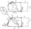
- FIG. 21A is a cross-sectional side view of a medical waste disposal system outside the scope of the invention, with an alternative form of tumbler located only partially within a hollow housing enclosure and with the tumbler illustrated in the fully open position;
- FIG. 21B is an enlarged partial cross-sectional side view of the housing enclosure and tumbler of the medical waste disposal system shown in FIG. 21A with the tumbler fully rotated in its closed position;
- FIG. 21C is an enlarged partial cross-sectional side view of tbe housing enclosure and tumbler of the medical waste disposal system shown in FIGS. 21A and 21B in the locked position; and
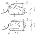
- FIG. 22 is a cross-sectional side view of a medical waste disposal system outside the scope of the invention, with an alternative form of tumbler located only partially within a hollow housing enclosure having a lid and with the tumbler illustrated in the fully closed position.
- Referring now to the drawing, wherein like reference numerals refer to like elements throughout, Fig. 1 shows a medical
waste disposal system 40 outside the scope of the present invention having ahollow housing enclosure 1 and ahollow disposal container 30 which are attached to each other and having a tumbler orpivotal closure 20 pivotally mounted withinhousing enclosure 1.Housing enclosure 1 is provided with a flap or ramp 10 which extends beneathhousing enclosure 1 and intodisposal container 30 as shown. Also shown in Fig. 1 are nbs 13 which reinforce the upper back interior portion ofhousing enclosure 1 and extend parallel to the cross-sectional plane of Fig. 1. -
Tumbler 20 forms a barrier which restricts access by a user both to the interior ofhousing enclosure 1 and to the interior ofdisposal container 30 whentumbler 20 is rotated to dispose of a sharp 42 (see FIG. 4A) deposited inhousing enclosure 1.Tumbler 20 is pivotally mounted insidehousing enclosure 1 bypivot pins 26 engaged inpivot brackets 8 formed on the interior ofhousing enclosure 1. By this construction,tumbler 20 can pivot about a pivot axis extending through opposite pivot pins 26. Although disclosed with respect to the use of pivot pins 26 andpivot brackets 8, it will be readily recognized by those of ordinary skill that other pivoting mechanisms may also be incorporated. As used in this application, the name "tumbler" refers to a pivoting mechanism which (a) closes and opens access to both the interior ofhousing enclosure 1 and the interior ofdisposal container 30, and (b) transfers sharp 42 from one position to another. At least one source of the name is the tumbling action which sharp 42 undergoes as it is transferred fromoutside housing enclosure 1 to the interior ofdisposal container 30 alongtumbler 20; specifically, sharp 42 may somersault as it falls downward. - Figs. 2A, 2B, 2C, 2D, 2E, and 2F respectively show a partial cross-sectional side view, a sectional planar view, a front planar view, a side view, a top planar view, and a bottom planar view of
housing enclosure 1 of medicalwaste disposal system 40 shown in Fig. 1 withflap 10 removed for clarity in Figs. 2B-2F.Ribs 13 are substantially flat projections of finite thickness which, as discussed above, extend parallel with the cross-sectional plane of Fig. 1, and are shown in detail in Figs. 2A-2F. Typically threeribs 13 are used. In addition to reinforcinghousing enclosure 1,ribs 13 may also be used to prevent over-rotation oftumbler 20 as shown in Figs. 9A and 9B and discussed in detail below. Also shown in Figs. 2A-2F are reinforcingprojections 6 which are provided to increase the rigidity ofhousing enclosure 1. Additional reinforcement may also be provided in other areas ofhousing enclosure 1 by addingribs 14 which are substantially flat projections of finite thickness as shown in Figs. 2C, 2D, 2E, and 2F. - As shown in Fig. 2A,
disposal container 30 is preferably snap-fitted ontohousing enclosure 1 in a conventional fashion as shown bylip 32 ofdisposal container 30 which is engaged by snap-tab 12 ofhousing enclosure 1. Other attachment mechanisms can be used as desired.Upper opening 3 is provided inhousing enclosure 1 to permit access to the interior ofhousing enclosure 1 for depositing sharps or other medical waste products to be disposed.Lower opening 4 is provided by the hollow ofhousing enclosure 1 to permit the sharps or medical waste products deposited to pass todisposal container 30.Pivot brackets 8 andflap 10 are attached to the interior ofhousing enclosure 1 which, depending on manufacturing capabilities and the desire of the user, may be formed integrally (i.e., in one piece) or may be separately constructed and then attached tohousing enclosure 1. - Fig. 3 shows in greater detail a cross-sectional side view of
tumbler 20 of medicalwaste disposal system 40 shown in Fig. 1.Tumbler 20 includes anupper portion 23 and a curvedlower portion 24 which are dimensioned so that together they extend acrossupper opening 3 ofhousing enclosure 1 when mounted and rotated inhousing enclosure 1.Upper portion 23 and curvedlower portion 24 may be used to prevent over-rotation oftumbler 20 as discussed in detail below. Curvedlower portion 24 has curvature sufficient to rotate within the curvature ofhousing enclosure 1 and also includes aflange 25 for engaginglower stop 9 ofhousing enclosure 1 shown in Fig. 2A. - To facilitate rotational movement of
tumbler 20,upper portion 23 also includes agrip 22 to allow the user to readily manipulatetumbler 20 when usingdisposal system 40.Grip 22 may be provided in a variety of configurations and is not necessarily confined within the interior ofhousing enclosure 1. As shown, for example, in Fig. 11,grip 22 may extend outside of and may be configured to engage a portion of the wall ofhousing enclosure 1. To provide for unimpeded rotation oftumbler 20, achute 28 is defined between a pair ofopposed side walls 19 intumbler 20 to ensure that any sharps to be disposed do not become wedged during rotation oftumbler 20. - Medical
waste disposal system 40 operates to allow waste to be loaded intoupper opening 3 ofhousing enclosure 1, where it causestumbler 20 to rotate. Astumbler 20 rotates, it simultaneously closes offupper opening 3 and openslower opening 4 inhousing enclosure 1 to allow the waste to drop intodisposal container 30. After the waste has dropped,tumbler 20 is weighted to return to its original position. Thus, by permitting onlyupper opening 3 orlower opening 4 to be substantially opened at any given point in time,tumbler 20 prevents the hand of a user from following the same path intodisposal container 30.Tumbler 20 can lock to prevent access to the interior ofhousing enclosure 1 anddisposal container 30 oncedisposal container 30 is filled. To further securedisposal system 40,lid 15 can be closed as described in greater detail below. - Use of the medical
waste disposal system 40 in the various stages of a disposal process will become readily apparent upon inspection of Figs. 4A, 4B, 5-7, 8A-8D, and 9A, and as now described. As shown in Figs. 4A and 4B, whenlid 15 andtumbler 20 are in the open position, a used sharp 42 may be passed throughupper opening 3 ofhousing enclosure 1 and placed on anouter portion 29 oftumbler 20, typically one at a time.Counterweight 27 is provided ontumbler 20 for adjusting the center of gravity oftumbler 20 to bias it in the inclined and open orientation shown in Fig. 4A prior to loading. - Fig. 4B illustrates the use of various instructions, directions, and signs to provide information to the user. Specifically,
lid 15 may haveinstructions 66 on its inner surface advising the user, for example, to "CLOSE AND SNAP LID BEFORE REPLACING CONTAINER."Upper portion 23 oftumbler 20 may havedirections 67 advising the user, for example, to "DROP SHARP HORIZONTALLY IN OPENING," "LIFT TABS TO ASSIST DEPOSIT," or both.Directions 67 may include arrows pointing the user in an appropriate direction. Finally,disposal container 30 may have asign 68 on its outer surface illustrating a recommended fill line and providing the user with cautionary information. - As shown in Fig. 5, any
sharps 42 which are deposited slide away fromupper portion 23 oftumbler 20 toward the back ofhousing enclosure 1. If sufficiently massive, the weight of anysharps 42 which are deposited causes tumbler 20 to pivot as shown in the sequence of Figs. 6 and 7, thereby droppingsharps 42 withindisposal container 30.Counterweight 27 may be adjusted so that rotation occurs upon the placement of a predetermined weight of sharps ontumbler 20. If sharp 42 does not have sufficient weight to overbalance the counterbalancing ofcounterweight 27, the user can manually cause sharp 42 to fall withindisposal container 30 in exactly the same fashion. This is accomplished by grasping and movinggrip 22 to pivottumbler 20 upwardly in relation togrip 22, to cause sharp 42 to fall intodisposal container 30. - When
disposal container 30 reaches full capacity,tumbler 20 is configured so that it will not return to the open position but remains rotated in a closed position. As shown in Fig. 8A, whendisposal container 30 is filled,tumbler 20, which is rotated to closeupper opening 3, is blocked from rotation in the opposite direction by the last sharp deposited. In this blocked orientation in the closed position,tumbler 20 does not permit any more waste to be deposited becauseupper opening 3 remains closed. Anindicator 60 is also provided to easily and quickly inform a user by a cursory inspection ofdisposal system 40 thatdisposal container 30 is filled and that the user should not attempt to deposit any more waste. As shown in Fig. 8B,indicator 60 may comprise printing or stamping the word "FULL" into the area oflower portion 24 oftumbler 20 which appears in plain view of a user inupper opening 3 whentumbler 20 is blocked in the closed position. - At this point, in order to further secure the contents within
disposal system 40 whendisposal container 30 is filled with waste (or when it is otherwise desired to be discarded), a user can further securedisposal system 40 by closing and lockinglid 15 tohousing enclosure 1. As shown in Fig. 2A,lid 15, which is shown in the open position, is pivotally mounted tohousing enclosure 1 byhinge 18 and has lockingtabs 16 which are configured to engage lockingaperture 17 ofhousing enclosure 1. As shown in Fig. 8C, upon rotatinglid 15 closed and pressing on lockingtabs 16 so that they engage lockingaperture 17 inhousing enclosure 1, a user may securely closedisposal container 30 by coveringupper opening 3. - Upon closing and locking
lid 15 in place, medicalwaste disposal system 40 is completely secured. This additional security measure further impedes or prevents access to the interior ofdisposal container 30 after it has been filled and securely closes medicalwaste disposal system 40 so that it may not be easily reopened. As shown in Fig. 8D, anindicator 61 may be provided onlid 15 which may comprise printing or stamping the word "FULL" into the outer surface oflid 15 to easily and quickly inform a user by a cursory inspection the condition ofdisposal system 40. As shown in Figs. 4B, 8B, and 8D, handles 31 may be provided ondisposal container 30 to facilitate transporting ofdisposal system 40. - As discussed above with respect to Fig. 3,
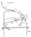
tumbler 20 includesupper portion 23 and curvedlower portion 24 which can include a variety of mechanisms to prevent over-rotation oftumbler 20. Shown in Fig. 9A is the use ofrib 13 as a stop forupper portion 23 which may be used in conjunction with or as an alternative for a stop provided byflange 25 of curvedlower portion 24 which engageslower stop 9 ofhousing enclosure 1. As shown in Fig. 9B,rib 13 may be configured in a variety of shapes to provide a stop forupper portion 23.Rib 13 may also be extended as shown in Figs. 12-16. As shown in Fig. 9B,upper portion 23 may be configured to includeweb 47 which rests uponhousing stop 48 provided onhousing enclosure 1 whentumbler 20 is in the fully open position shown in Fig. 10D. As shown in Fig. 10A,upper portion 23 may also be configured so that it engages anupper stop 7 inhousing enclosure 1 and may be provided as a replacement for or an additional structure to be used withrib 13 for preventing over-rotation oftumbler 20. As shown in Fig. 10A,upper stop 7 is constructed by configuring and positioning reinforcingprojections 6 so that they engageupper portion 23 thereby impeding movement ofupper portion 23 to prevent over-rotation oftumbler 20. - Alternatives to the stop mechanism provided by
flange 25 andlower stop 9 shown in Figs. 9A and 10A may also be incorporated to prevent over-rotation oftumbler 20. Figs. 9B and 10D-10K showalternative housing enclosures 1 which incorporate a stop mechanism provided by ascoop 2 which is a curved projection on the inner surface ofhousing enclosure 1.Scoop 2 has a curved profile which permitslower portion 24 to move freely but prevents over-rotation oflower portion 24 upon rotatingtumbler 20. As shown in Fig. 9B,scoop 2 may be added as a back-up stop mechanism to be used in conjunction with an upper stop mechanism such asrib 13 or may be used as the sole stop mechanism fortumbler 20 as shown in Figs. 10D-10K. The stop mechanism provided byscoop 2 is particularly well-suited for use withtumbler 20 shown in Fig. 9B having anangled tip portion 21 which is discussed in detail below with respect to Figs. 10D-10K. - As shown in Figs. 10A-10K,
ribs 13 are not required and may be eliminated fromhousing enclosure 1 as both a reinforcing structure and a stop mechanism provided that the shape and thickness ofhousing enclosure 1 are adjusted to accommodate the in-service stresses to whichdisposal system 40 will be subjected and an alternative stop mechanism is provided fortumbler 20. An exemplary system withoutribs 13 is shown in Fig. 10D which hasalternative housing enclosure 1 withscoop 2 used in conjunction withtumbler 20 having angledtip portion 21. - Operation of this system is shown beginning with Fig. 10D in which a used sharp 42 is passed through
upper opening 3 ofhousing enclosure 1 and placed ontotumbler 20 whenlid 15 andtumbler 20 are in the open position. The weight of anysharps 42 which are deposited causes tumbler 20 to pivot thereby droppingsharps 42 throughlower opening 4 inhousing enclosure 1 as shown sequentially in Figs. 10E-10K. As shown in Fig. 10E, anysharps 42 which are deposited slide along the firststraight portion 70 toward angledtip portion 21 oftumbler 20 and rest incrux 41 formed intumbler 20 between firststraight portion 70 andangled tip portion 21. - The specific angle of
angled tip portion 21 is adjusted to maintain sharp 42 ontumbler 20 until angledtip portion 21 is rotated adjacent toflap 10 as shown in Figs. 10E-10F. Upon further rotation oftumbler 20, as shown in Fig. 10G, sharp 42 slides towardflap 10 and passes betweenangled tip portion 21 andflap 10 and throughlower opening 4. As shown in Fig. 10G,lower opening 4 permits passage of sharp 42 while accessibility beyond the interior ofhousing enclosure 1 intodisposal container 30 is simultaneously blocked as shown by the line of sight designated "L." In this manner, sharp 42 may be safely disposed without the need to fully rotateupper portion 23 to closeupper opening 3 which is especially advantageous in the case that tumbler 20 is prevented from rotating to the closed position (e.g., in the case that tumbler 20 becomes jammed). - As shown in Figs. 10H-10J, upon further rotating
tumbler 20,upper portion 23 closesupper opening 3 to continuously prevent access to the interior ofhousing enclosure 1. Over-rotation oftumbler 20 is prevented byscoop 2 which contacts firststraight portion 70 oftumbler 20 and prevents further rotation oftumbler 20 as shown in Fig. 10J. As shown in Fig. 10K, upon rotatinglid 15 closed and pressing on lockingtabs 16 so that they engage lockingaperture 17 inhousing enclosure 1, a user may securely close and coverupper opening 3 inhousing enclosure 1. - As can be seen in Fig. 1, lid or cover 15 is separate from and independent of
tumbler 20. This provides the distinct advantage to the user that, in the event of a malfunction oftumbler 20, wheretumbler 20 may be jammed in the open or partially open position, the user can simply closelid 15 andlock lid 15 shut, independent of the tumbler position. This differs from other disposal systems which rely on movement of a pivotal closure or tumbler to accomplish both the independent and separate functions of (1) disposing ofsharps 42, and (2) locking the housing enclosure and container shut when disposal is complete. Thus, unlike other disposal systems which do not include separate andindependent lid 15 andtumbler 20 components, the construction shown allows the user to securely shut and lockwaste disposal system 40 at any time, thereby preventing a potentially dangerous situation. Thus, the user is doubly protected from inadvertently extending fingers withindisposal container 30. -
Disposal system 40 also preventssharps 42 from passing or being ejected back throughupper opening 3 ofdisposal container 30. By shaping the back interior portion ofhousing enclosure 1 with a squared or sloping contour,sharps 42 which are loaded intohousing enclosure 1 are deflected away fromupper opening 3. Thus, by shapinghousing enclosure 1 in this manner, the present invention eliminates the need for a pivotal closure having a retention pocket to deflect and maintainsharps 42 withindisposal container 30. - Fig. 1 shows an
exemplary housing enclosure 1 having a squaredcontour portion 35. Fig. 11, which shows an embodiment of the invention, shows anexemplary housing enclosure 1 having a slopedcontour portion 36 extending downwardly towardupper opening 3. Preferably, sloped contouredportion 36 is formed in a parabolic shape; this shape further enhances the downward deflection ofsharps 42. The back portion ofhousing enclosure 1 may also be configured to have an "S"-shapedportion 37 as shown in Figs. 17-20. - Also shown in Fig. 11 are two additional features which help to prevent
sharps 42 from being ejected fromhousing enclosure 1, namely,end flap 44 and memory hinge 45 which are incorporated intotumbler 20. By providingtumbler 20 with amemory hinge 45 which is flexible and bendable,end flap 44 is permitted to yield and bend to form an angled tip portion rather than ejectingsharps 42 upon being subjected to any stress created by rotation oftumbler 20. Because it is made of a plastic material having a memory,memory hinge 45 will induceend flap 44 to return to its original, pre-bending position. - As shown by Figs. 12-20, medical
waste disposal system 40 may be provided with a variety ofhousing enclosure 1,tumbler 20, andlid 15 configurations and may be loaded with and used to dispose ofmedical sharps 42 and other waste in a variety of sizes. - FIGS. 21A, 21B, and 21C illustrate yet another
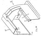
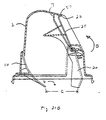
waste disposal system 40 outside the scope of the present invention. In theprevious systems tumbler 20 was fully contained within the confines of housing enclosure 1 (although, in some previous systems,grip 22 oftumbler 20 extended beyond those confines). As illustrated in FIG. 21A, however, a significant portion oftumbler 20 extends beyondhousing enclosure 1, whentumbler 20 is in the fully open position and ready to receive sharp 42 for disposal, in the embodiment shown in FIGS. 21A, 21B, and 21C. The user places sharp 42 ontumbler 20, as for the other embodiments, throughupper opening 3.Upper opening 3 may have a dimension "A" of about 41 mm (15/8 inches). One advantage of this system is thatpivot bracket 8 and pivot pins 26 can be formed in the outer wall ofhousing enclosure 1. - Fig. 21B illustrates
tumbler 20 when it has been fully rotated to its closed position in the direction of arrow "B."Grip 22 oftumbler 20contacts lip 80 onhousing enclosure 1 to fully closeupper opening 3. At this point,lower opening 4 ofhousing enclosure 1 is fully open to receive sharp 42 as it passes fromhousing enclosure 1 intodisposal container 30. Likeupper opening 3,lower opening 4 may have a dimension "C" of about 41 mm (1 5/8 inches). - FIG. 21C shows
tumbler 20 in the locked position.Grip 22 performs two functions in the embodiment ofwaste disposal system 40 shown in FIGS. 21A, 21B, and 21C. First, as in the other systems,grip 22 allows the user to manipulatetumbler 20. In this system, however,grip 22 also provides a mechanism to locktumbler 20 and securely closeupper opening 3. Specifically, whendisposal container 30 is full, the user can pushgrip 22past lip 80 and into engagement withupper stop 7 onhousing enclosure 1. This locksgrip 22 betweenlip 80 andupper stop 7 and, therefore, lockstumbler 20 into a closed position overupper opening 3. Thus, it is possible to eliminatelid 15. - FIG. 22 illustrates another
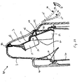
waste disposal system 40 outside the scope of the present invention. This system combines several features disclosed above with respect to other systems. Specifically, like the system of FIGS. 21A, 21B, and 21C, a significant portion oftumbler 20 extends beyondhousing enclosure 1 whentumbler 20 is in the fully open position and ready to receive sharp 42 for disposal. (Tumbler 20 is shown in the fully closed position in FIG. 22.) One potential disadvantage of the system of FIGS. 21A, 21B, and 21C is that sharp 42 may become wedged betweentumbler 20 and thefront wall 82 ofhousing enclosure 1. If so, the wedged sharp 42 may preventtumbler 20 from fully closing. Thewaste disposal system 40 shown in FIG. 22 avoids this problem by incorporating thememory hinge 45 of the embodiment shown in Fig. 11. - As for the embodiment of FIG. 11,
memory hinge 45 is flexible and bendable, permittinglower portion 24 oftumbler 20 to yield and bend to form an angled tip portion. Agroove 84 is formed intumbler 20, separatingside walls 19 into two segments, adjacent tomemory hinge 45.Groove 84 provides clearance astumbler 20 bends aboutmemory hinge 45. For example, groove 84 may simply permit one segment ofside walls 19 to slide or otherwise pass by the other segment of side walls 19 (side walls 19 may have a bevel in the area ofgroove 84 to facilitate such movement) astumbler 20 bends aboutmemory hinge 45. Alternatively, groove 84 may be sized so that the two segments ofside walls 19 do not meet at all astumbler 20 bends aboutmemory hinge 45. Should a sharp 42 become wedged betweenlower portion 24 oftumbler 20 andfront wall 82 ofhousing enclosure 1,tumbler 20 will bend aboutmemory hinge 45 into its fully closed position coveringupper opening 3. -
Memory hinge 45 will inducetumbler 20 to return to its original, pre-bending position because it is made of a plastic material having a memory. Alternatively, rather than a memory hinge,tumbler 20 may have a hinge which simply yields under the pressure exerted by a wedged sharp 42 againsttumbler 20. Such a hinge need not be made of a plastic material having a memory; any yielding material would be suitable. A frangible hinge may also be provided which simply breaks when a sharp 42, wedged betweenlower portion 24 oftumbler 20 andfront wall 82 ofhousing enclosure 1, exerts pressure againsttumbler 20. - Another
waste disposal system 40 outside the scope of the present invention illustrated in FIG. 22 also incorporates the advantages of alid 15. As for the system of FIGS. 21A, 21B, and 21C,grip 22 provides a mechanism to locktumbler 20 and securely closeupper opening 3. The system of FIG. 22 provides a double-locking closure, however, because that system also incorporateslid 15.Lid 15 is shown in the fully closed position in solid lines in FIG. 22.Catch 86 on the end oflid 15 engages a snap-in-slot near the top ofhousing enclosure 1 to securely locklid 15 in a closed position overupper opening 3.Lid 15 pivots about holdinglugs 88 provided infront wall 82 ofhousing enclosure 1. - As shown in dashed lines in FIG. 22, lid 15' allows unrestricted access to
upper opening 3 in its fully open position. Whendisposal container 30 is full ofsharps 42,tumbler 20 is locked into its closed position overupper opening 3. Then lid 15' is rotated in the direction of arrows "D" into the closed position shown by the solid lines oflid 15. Lid 15' may require post-bending during the closure process to a position represented by the dashed lines oflid 15" in FIG. 22. Brackets 90 may be used to attachwaste disposal system 40 to a wall or other suitable mounting structure. - Preferably,
housing enclosure 1,tumbler 20, lid 15 (if provided), anddisposal container 30 are made of various plastic materials which may be injection-molded.Disposal container 30 andlid 15 may also be made at least partially of a translucent or transparent material so that the contents ofdisposal container 30 can be viewed easily to facilitate detection of whendisposal container 30 is sufficiently full ofsharps 42 such that it should be removed and emptied or replaced. It will be readily recognized that other structures, such as a photoelectric sensor and transmitter mounted indisposal container 30, may also be used to determine the level of contents withindisposal container 30. - It is envisioned and to be understood that the various configurations of the various components shown in the drawing and used in medical
waste disposal system 40 of the present invention, including but not limited tohousing enclosure 1,lid 15,tumbler 20, anddisposal container 30, may be incorporated either in place of or in combination with any of the configurations disclosed to the extent that the parts are interchangeable. Although illustrated and described herein with reference to certain specific embodiments, the present invention is nevertheless not intended to be limited to the details shown, but only by the scope of the claims.
Claims (17)
- A disposal apparatus (40) for receiving medical waste (42) comprising:a disposal container (30) having a top opening and an interior surface defining a space adapted to collect medical waste to be disposed;a housing enclosure (1) positioned over the top opening of the disposal container (30), the housing endosure (1) having an interior surface defining an interior of the housing enclosure (1), an upper opening permitting access to the interior of the housing enclosure (1), a lower opening (4) adjacent to the space in the disposal container (30), anda tumbler (20) mounted at least partially within the housing enclosure (1) with an upper portion positioned adjacent the upper opening (3) of the housing enclosure (1), the tumbler (20) restricting access to the interior of the housing enclosure (1) and being pivotally mounted and adapted to rotate between:(a) an open position in which the upper opening (3) is substantial free of the tumbler (20) to permit loading of the medical waste onto the tumbler and into the interior of the housing enclosure (1) and the lower opening (4) is substantially blocked by the tumbler (20), and(b) a closed position in which the upper opening (3) is substantially blocked by the tumbler (20) and the lower opening (4) is substantially free of the tumbler (20) to permit the medical waste (42) to pass from the housing enclosure (1) into the space of the disposal container (30);
wherein said interior surface of said housing endosure (1) defines a portion (35, 36, 37) located above the lower opening (4) of said housing enclosure (1) at an elevation spaced above the top opening of the disposal container (30), which portion (35, 36, 37) is contoured to deflect medical waste received in the housing enclosure (1) away from the upper opening (3) and into the disposal container (30), and
wherein the medical waste (42) collected in the space of the disposal container (30) blocks the tumbler (20) in the closed position and prevents rotation of the tumbler (20) to the open position when the disposal container (30) is filled with the medical waste (42),
characterised in that the tumbler (20) has an end flap (44) for engaging the medical waste (42) and a flexible memory hinge (45) disposed proximate the end flap (44), the memory hinge (45) yielding to prevent the end flap (44) from ejecting the medical waste (42) from the housing enclosure (1) through the upper opening (3). - The disposal apparatus according to claim 1, further comprising:a lid (15) adapted to cover the upper opening (3) of the housing enclosure (1); andmeans for rotatably attaching the lid (15) to the housing enclosure (1).
- The disposal apparatus according to claim 1, wherein the portion (35) has a substantially square contour.
- The disposal apparatus according to claim 1, wherein the portion (36) has a sloped contour extending downwardly toward the upper opening (3).
- The disposal apparatus according to claim 1, wherein the portion (36) has a contour which is substantially parabolic.
- The disposal apparatus according to claim 1, wherein the portion (37) has a substantially S-shaped contour.
- The disposal apparatus according to claim 1, wherein the housing enclosure (1) has a stop means for preventing rotation of the tumbler (20) beyond a predetermined position to maintain the upper opening (3) blocked by the tumbler (20).
- The disposal apparatus according to claim 7, wherein the stop means includes at least one stop mechanism engaging the tumbler (20) and projecting from an interior surface of the housing enclosure (1), the at least one stop mechanism being selected from the group consisting of a rib (13), an upper stop (7), a scoop (2), and combinations thereof.
- The disposal apparatus according to claim 1, wherein the tumbler (20) has a flange (25) and an interior surface of the housing enclosure (1) has a stop (9) which engages the flange and prevents rotation of the tumbler (20) beyond a predetermined Position to maintain the upper opening blocked by the tumbler (20).
- The disposal apparatus according to claim 1, wherein the housing enclosure (1) has a stop (48) and an upper portion of the tumbler (20) has a web (47) contacting the housing stop (49) when the tumbler (20) is in the open position.
- The disposal apparatus according to claim 1, wherein the tumbler (20) has a chute preventing the medical waste (42) from wedging during rotation of the tumbler (20).
- The disposal apparatus according to claim 1, wherein the tumbler (20) has a counterweight (27) adjusting the center of gravity of the tumbler (20) to bias the tumbler in the open position.
- The disposal apparatus according to claim 1, wherein
the tumbler (20) has an angled tip portion positioned adjacent to an interior surface of the housing enclosure (1) for maintaining the medical waste (42) on the tumbler (20) until the angled tip portion is rotated adjacent to the lower opening (4), at which point the medical waste (42) passes through the lower opening (4) into the disposal container. - The disposal apparatus according to claim 1, wherein rotation of the tumbler (20) occurs upon the placement of a predetermined weight of medical waste (42) on the tumbler (20).
- The disposal apparatus according to claim 1, wherein the disposal container includes a handle (31) to facilitate transporting of the disposal apparatus (40).
- The disposal apparatus according to claim 1, wherein the center of gravity of the tumbler (20) is adjusted to bias the tumbler (20) in the open position prior to loading the medical waste into the tumbler (20).
- The disposal apparatus according to claim 1, wherein the blocked tumbler (20) indicates that the disposal container (20) is filled with the medical waste (42).
Priority Applications (1)
| Application Number | Priority Date | Filing Date | Title |
|---|---|---|---|
| EP05019701A EP1609432B1 (en) | 1996-11-15 | 1997-11-14 | Medical waste disposal container |
Applications Claiming Priority (6)
| Application Number | Priority Date | Filing Date | Title |
|---|---|---|---|
| US3101696P | 1996-11-15 | 1996-11-15 | |
| US31016P | 1996-11-15 | ||
| US3921197P | 1997-02-28 | 1997-02-28 | |
| US39211P | 1997-02-28 | ||
| US08/969,075 US5947285A (en) | 1996-11-15 | 1997-11-12 | Medical waste disposal container |
| US969075 | 1997-11-12 |
Related Child Applications (1)
| Application Number | Title | Priority Date | Filing Date |
|---|---|---|---|
| EP05019701A Division EP1609432B1 (en) | 1996-11-15 | 1997-11-14 | Medical waste disposal container |
Publications (2)
| Publication Number | Publication Date |
|---|---|
| EP0842641A1 EP0842641A1 (en) | 1998-05-20 |
| EP0842641B1 true EP0842641B1 (en) | 2006-02-15 |
Family
ID=27363770
Family Applications (2)
| Application Number | Title | Priority Date | Filing Date |
|---|---|---|---|
| EP05019701A Expired - Lifetime EP1609432B1 (en) | 1996-11-15 | 1997-11-14 | Medical waste disposal container |
| EP97119980A Expired - Lifetime EP0842641B1 (en) | 1996-11-15 | 1997-11-14 | Medical waste disposal container |
Family Applications Before (1)
| Application Number | Title | Priority Date | Filing Date |
|---|---|---|---|
| EP05019701A Expired - Lifetime EP1609432B1 (en) | 1996-11-15 | 1997-11-14 | Medical waste disposal container |
Country Status (7)
| Country | Link |
|---|---|
| US (1) | US5947285A (en) |
| EP (2) | EP1609432B1 (en) |
| AT (2) | ATE495711T1 (en) |
| CA (1) | CA2221187C (en) |
| DE (2) | DE69740103D1 (en) |
| DK (1) | DK0842641T3 (en) |
| ES (1) | ES2258784T3 (en) |
Cited By (2)
| Publication number | Priority date | Publication date | Assignee | Title |
|---|---|---|---|---|
| CN103318584A (en) * | 2013-06-19 | 2013-09-25 | 义乌市一清城市环境卫生管理有限公司 | Charging mechanism of garbage collection device |
| US8998031B2 (en) | 2011-08-26 | 2015-04-07 | Stericycle, Inc. | Waste container assembly |
Families Citing this family (47)
| Publication number | Priority date | Publication date | Assignee | Title |
|---|---|---|---|---|
| AUPP353398A0 (en) * | 1998-05-15 | 1998-06-04 | Catilina Nominees Pty Ltd | Sharps container |
| US6283909B1 (en) * | 1999-01-22 | 2001-09-04 | Fraser R. Sharp | Container for supplying medical products and disposal of medical waste material |
| US6876991B1 (en) | 1999-11-08 | 2005-04-05 | Collaborative Decision Platforms, Llc. | System, method and computer program product for a collaborative decision platform |
| US8201704B2 (en) * | 2001-04-30 | 2012-06-19 | Brian Finnestad | Medical waste disposal system |
| US7114629B2 (en) * | 2001-04-30 | 2006-10-03 | Tyco Healthcare Group Lp | Medical waste disposal system |
| US20030213714A1 (en) * | 2002-05-17 | 2003-11-20 | Moats Donna L. | Low profile sharps container system |
| GB2398225B (en) * | 2003-02-12 | 2007-02-28 | Daniels Healthcare Ltd | Medical waste disposal containers |
| US8029525B2 (en) * | 2003-07-31 | 2011-10-04 | Panasonic Corporation | Puncture instrument, puncture needle cartridge, puncture instrument set, and puncture needle disposal instrument |
| US8195328B2 (en) | 2003-09-19 | 2012-06-05 | Vesta Medical, Llc | Combination disposal and dispensing apparatus and method |
| WO2005029286A2 (en) | 2003-09-19 | 2005-03-31 | Vesta Medical, Llc | System and method for sorting medical waste for disposal |
| US7562025B2 (en) | 2003-09-19 | 2009-07-14 | Vesta Medical, Llc | Waste sorting system with query function, and method thereof |
| US7660724B2 (en) | 2003-09-19 | 2010-02-09 | Vesta Medical, Llc | Waste sorting system utilizing removable liners |
| DE102004014826A1 (en) * | 2004-03-24 | 2005-10-06 | Udo Heisig Gmbh | waste container |
| US7644834B2 (en) | 2004-05-27 | 2010-01-12 | Navilyst Medical, Inc. | Splash minimizing lid for liquid waste receptacle |
| US7344027B2 (en) * | 2004-06-07 | 2008-03-18 | Ultimed, Inc. | Sharps container for “no-touch,” sequential safe storage of used pen needles |
| WO2005120610A2 (en) * | 2004-06-07 | 2005-12-22 | Ultimed, Inc. | Sharps container for used pen needle assemblies |
| US7971715B1 (en) * | 2004-11-15 | 2011-07-05 | Deroyal Industries, Inc. | Medical disposables containers |
| US20060219718A1 (en) * | 2005-04-05 | 2006-10-05 | Sherwood Services, Ag | Integral tortuous path receptacle cover |
| US20070069490A1 (en) * | 2005-09-23 | 2007-03-29 | John Japuntich | Sharps container configured for cart mounting |
| US7878358B2 (en) * | 2005-09-26 | 2011-02-01 | Covidien Ag | Multiple container cart with individual foot pedal/lid actuation |
| US7789230B2 (en) * | 2005-09-27 | 2010-09-07 | Covidien Ag | Method and apparatus for collecting sharps |
| US20070068833A1 (en) * | 2005-09-27 | 2007-03-29 | Smudde Anton M | Method and apparatus for collecting sharps |
| US8875881B2 (en) * | 2005-09-27 | 2014-11-04 | Covidien Ag | Method and apparatus for collecting sharps |
| WO2007038133A1 (en) * | 2005-09-27 | 2007-04-05 | Covidien Ag | Method and apparatus for collecting sharps |
| US8584850B2 (en) * | 2005-09-27 | 2013-11-19 | Covidien Ag | Apparatus for collecting sharps |
| US20070080223A1 (en) * | 2005-10-07 | 2007-04-12 | Sherwood Services Ag | Remote monitoring of medical device |
| US20070295722A1 (en) * | 2006-06-23 | 2007-12-27 | Titas Richard P | Sanitary waste bin and system |
| CN101229873B (en) * | 2007-01-26 | 2012-04-11 | 卡达莲娜·罗末丽有限公司 | Storage bin for disposing medical sharp device and waste |
| US20080199299A1 (en) * | 2007-02-15 | 2008-08-21 | Baader Dennis L | Methods and apparatus for hands-free disposal of medical waste products |
| US20120024878A1 (en) * | 2010-03-29 | 2012-02-02 | Express Scripts, Inc. | Lids for securing items in containers |
| US8573426B2 (en) | 2010-04-27 | 2013-11-05 | Cactus, Llc | Pharmaceutical waste disposal assembly |
| US8616397B2 (en) | 2010-04-27 | 2013-12-31 | Cactus, Llc | Pharmaceutical waste disposal assembly including waste diverter |
| US9044377B2 (en) | 2010-04-27 | 2015-06-02 | Cactus, Llc | Pharmaceutical waste disposal assembly |
| US8348056B2 (en) | 2010-06-03 | 2013-01-08 | Cactus Llc | Pharmaceutical waste disposal assembly |
| CN103079492B (en) * | 2010-07-06 | 2015-05-20 | 贝克顿·迪金森公司 | Sharps container |
| US8397933B2 (en) | 2010-08-10 | 2013-03-19 | Covidien Lp | Medical waste receptable |
| US8505769B2 (en) | 2010-08-10 | 2013-08-13 | Covidien Lp | Medical waste receptacle |
| US8534459B2 (en) | 2010-12-29 | 2013-09-17 | Cactus, Llc | Cancellation feature for pharmaceutical waste disposal assembly |
| ES2393605B1 (en) * | 2011-06-02 | 2013-11-04 | Mecamesor, S.A. | BOX FOR WASTE CONTAINER WITH LOAD CONTROL SYSTEM. |
| CN103274144B (en) * | 2013-06-18 | 2015-12-09 | 东华大学 | A kind of foot-operated inside and outside partition rubbish container |
| CN103274147A (en) * | 2013-06-18 | 2013-09-04 | 东华大学 | Outwardly-isolated garbage can |
| EP3085325A1 (en) * | 2015-04-20 | 2016-10-26 | Carebay Europe Ltd. | Device for handling medicament delivery devices |
| US10321968B2 (en) | 2015-10-23 | 2019-06-18 | Medline Industries, Inc. | Sharps container |
| US11011268B2 (en) * | 2018-01-15 | 2021-05-18 | Ark Technologies Llc | System and method for managing medical waste received in one or more containers |
| CN111110363B (en) * | 2019-12-31 | 2021-01-05 | 中国人民解放军陆军军医大学第一附属医院 | Medical instrument picking device |
| CN113233033B (en) * | 2021-06-01 | 2022-08-12 | 陕西科技大学 | Intelligent classification dustbin |
| WO2023010181A1 (en) * | 2021-08-06 | 2023-02-09 | Smartstream Pty Ltd | A scalpel blade container |
Family Cites Families (32)
| Publication number | Priority date | Publication date | Assignee | Title |
|---|---|---|---|---|
| US33413A (en) * | 1861-10-01 | William h | ||
| US457918A (en) * | 1891-08-18 | And royal m | ||
| US449149A (en) * | 1891-03-31 | Letter-box | ||
| US697655A (en) * | 1901-08-03 | 1902-04-15 | Michael O'leary | Garbage-can. |
| US1333051A (en) * | 1917-03-14 | 1920-03-09 | Young Harvey | Closure for garbage-cans |
| GB473199A (en) * | 1936-04-07 | 1937-10-07 | Else Fiedler | Improvements in or relating to dust-bins and the like |
| US4032037A (en) * | 1976-04-07 | 1977-06-28 | Airfix Plastics Limited | Closure and fastener for trash bins |
| US4315592A (en) * | 1980-09-18 | 1982-02-16 | Smith Daniel L | Disposable receptable for expendable item |
| DE3145152A1 (en) * | 1980-11-19 | 1982-06-24 | Frontier Plastics (South Wales) Ltd., Crosskeys, Gwent | "CONTAINER FOR RECEIVING WASTE" |
| GB8405390D0 (en) * | 1984-03-01 | 1984-04-04 | Frontier Plastics South Wales | Containers |
| DE8503511U1 (en) * | 1985-02-08 | 1985-06-27 | Zanker, Helmut, 7000 Stuttgart | Combination of devices for medical purposes |
| US4714168A (en) * | 1986-06-30 | 1987-12-22 | Johnson William G | Container for disposable expended medical supplies |
| US4779728A (en) * | 1986-11-24 | 1988-10-25 | Sage Products, Inc. | Sharps disposal container |
| US4715498A (en) * | 1986-11-24 | 1987-12-29 | Sage Products, Inc. | Sharps disposal system |
| USRE33413E (en) | 1986-11-24 | 1990-10-30 | Sage Products, Inc. | Sharps disposal system |
| US5413243A (en) * | 1987-04-20 | 1995-05-09 | Bemis Manufacturing Company | Sharps disposal container |
| US4804090A (en) * | 1987-08-28 | 1989-02-14 | Schuh Ronald A | Sharps disposal system |
| US4890733A (en) * | 1988-03-01 | 1990-01-02 | Anderson Robert S | Disposal receptacle for used, sharp, medical instruments or other biohazards |
| US4809850A (en) * | 1988-03-28 | 1989-03-07 | Custom Medical Plastics, Inc. | Self-closing sharps container with hand protection |
| US4863057A (en) * | 1988-04-29 | 1989-09-05 | Sage Products, Inc. | Dual locked container system |
| US4828107A (en) * | 1988-07-25 | 1989-05-09 | Treesa Spencer | Disposable container for syringes |
| US4903832A (en) * | 1989-01-19 | 1990-02-27 | Winfield Corporation | Method and apparatus for cleanly storing and disposing of discarded articles |
| US4927076A (en) * | 1989-01-24 | 1990-05-22 | Hemox, Inc. | Medical appliance disposal container |
| US4955477A (en) * | 1989-07-24 | 1990-09-11 | John Bruno | Receptacle for storage and disposal of potentially injurious implements such as used scalpel blades, hypodermic needles and the like |
| US5080251A (en) * | 1989-07-28 | 1992-01-14 | Devon Industries, Inc. | Tortuous path in-patient room medical waste disposal container |
| US5076429A (en) * | 1989-11-28 | 1991-12-31 | Voluntary Hospitals Of America | Sharps container |
| US5178322A (en) * | 1989-12-05 | 1993-01-12 | Med-Safe Systems, Inc. | Multiple configuration disposable sharps container system |
| US5103997A (en) * | 1990-11-26 | 1992-04-14 | Med-Safe Systems, Inc. | Combination disposable sharps container and mounting bracket |
| US5240108A (en) * | 1990-11-26 | 1993-08-31 | Kaiser Foundation Hospitals | Sharps disposal system |
| US5387735A (en) * | 1993-04-08 | 1995-02-07 | Sage Products, Inc. | Sharps disposal container and system |
| US5494186A (en) * | 1993-05-17 | 1996-02-27 | Devon Industries, Inc. | Wall mounted medical waste disposal container with pivoted top closure lid |
| US5603404A (en) * | 1995-09-29 | 1997-02-18 | Nazare; Raymond | Sharps container |
-
1997
- 1997-11-12 US US08/969,075 patent/US5947285A/en not_active Expired - Lifetime
- 1997-11-14 CA CA002221187A patent/CA2221187C/en not_active Expired - Fee Related
- 1997-11-14 AT AT05019701T patent/ATE495711T1/en not_active IP Right Cessation
- 1997-11-14 AT AT97119980T patent/ATE317672T1/en not_active IP Right Cessation
- 1997-11-14 DE DE69740103T patent/DE69740103D1/en not_active Expired - Lifetime
- 1997-11-14 ES ES97119980T patent/ES2258784T3/en not_active Expired - Lifetime
- 1997-11-14 EP EP05019701A patent/EP1609432B1/en not_active Expired - Lifetime
- 1997-11-14 DK DK97119980T patent/DK0842641T3/en active
- 1997-11-14 EP EP97119980A patent/EP0842641B1/en not_active Expired - Lifetime
- 1997-11-14 DE DE69735256T patent/DE69735256T2/en not_active Expired - Lifetime
Cited By (3)
| Publication number | Priority date | Publication date | Assignee | Title |
|---|---|---|---|---|
| US8998031B2 (en) | 2011-08-26 | 2015-04-07 | Stericycle, Inc. | Waste container assembly |
| US9585719B2 (en) | 2011-08-26 | 2017-03-07 | Stericycle, Inc. | Waste container assembly |
| CN103318584A (en) * | 2013-06-19 | 2013-09-25 | 义乌市一清城市环境卫生管理有限公司 | Charging mechanism of garbage collection device |
Also Published As
| Publication number | Publication date |
|---|---|
| US5947285A (en) | 1999-09-07 |
| DE69740103D1 (en) | 2011-03-03 |
| DK0842641T3 (en) | 2006-06-19 |
| ATE495711T1 (en) | 2011-02-15 |
| EP0842641A1 (en) | 1998-05-20 |
| CA2221187C (en) | 2008-02-05 |
| DE69735256T2 (en) | 2007-03-01 |
| ES2258784T3 (en) | 2006-09-01 |
| DE69735256D1 (en) | 2006-04-20 |
| CA2221187A1 (en) | 1998-05-15 |
| EP1609432B1 (en) | 2011-01-19 |
| ATE317672T1 (en) | 2006-03-15 |
| EP1609432A1 (en) | 2005-12-28 |
Similar Documents
| Publication | Publication Date | Title |
|---|---|---|
| EP0842641B1 (en) | Medical waste disposal container | |
| CA2114987C (en) | Sharps disposal container and system | |
| EP1001820B1 (en) | Sharps container | |
| US8162139B2 (en) | Sharps disposal system | |
| US4715498A (en) | Sharps disposal system | |
| US5570783A (en) | Apparatus and methods for transporting and discarding medical materials | |
| US5647502A (en) | Wall mounted medical waste disposal container with pivoted top closure lid | |
| US5630506A (en) | Apparatus and method for transporting and discarding medical materials | |
| AU642974B2 (en) | Disposable sharp instrument container | |
| US5154345A (en) | Secure container for disposable sharps | |
| US10617485B2 (en) | Sharps container | |
| US5967317A (en) | Syringe orienting disposable container | |
| USRE33413E (en) | Sharps disposal system | |
| RU2435545C2 (en) | Container for disposal of medical sharp objects and wastes | |
| EP0431879B1 (en) | A secure container for disposable sharps | |
| AU747319B2 (en) | Sharps container | |
| ES2360069T3 (en) | CONTAINER FOR THE ELIMINATION OF MEDICAL WASTE. | |
| MXPA97007171A (en) | Apparatus and method for the transportation and discarding of medium materials | |
| GB2442570A (en) | Sharps container with handle connected closure | |
| MXPA00000379A (en) | Sharps container |
Legal Events
| Date | Code | Title | Description |
|---|---|---|---|
| PUAI | Public reference made under article 153(3) epc to a published international application that has entered the european phase |
Free format text: ORIGINAL CODE: 0009012 |
|
| AK | Designated contracting states |
Kind code of ref document: A1 Designated state(s): AT BE CH DE DK ES FI FR GB IT LI NL SE |
|
| AX | Request for extension of the european patent |
Free format text: AL;LT;LV;MK;RO;SI |
|
| 17P | Request for examination filed |
Effective date: 19981120 |
|
| AKX | Designation fees paid |
Free format text: AT BE CH DE DK ES FI FR GB IT LI NL SE |
|
| RBV | Designated contracting states (corrected) |
Designated state(s): AT BE CH DE DK ES FI FR GB IT LI NL SE |
|
| 17Q | First examination report despatched |
Effective date: 20020314 |
|
| GRAP | Despatch of communication of intention to grant a patent |
Free format text: ORIGINAL CODE: EPIDOSNIGR1 |
|
| GRAS | Grant fee paid |
Free format text: ORIGINAL CODE: EPIDOSNIGR3 |
|
| GRAA | (expected) grant |
Free format text: ORIGINAL CODE: 0009210 |
|
| AK | Designated contracting states |
Kind code of ref document: B1 Designated state(s): AT BE CH DE DK ES FI FR GB IT LI NL SE |
|
| PG25 | Lapsed in a contracting state [announced via postgrant information from national office to epo] |
Ref country code: IT Free format text: LAPSE BECAUSE OF FAILURE TO SUBMIT A TRANSLATION OF THE DESCRIPTION OR TO PAY THE FEE WITHIN THE PRESCRIBED TIME-LIMIT;WARNING: LAPSES OF ITALIAN PATENTS WITH EFFECTIVE DATE BEFORE 2007 MAY HAVE OCCURRED AT ANY TIME BEFORE 2007. THE CORRECT EFFECTIVE DATE MAY BE DIFFERENT FROM THE ONE RECORDED. Effective date: 20060215 Ref country code: AT Free format text: LAPSE BECAUSE OF FAILURE TO SUBMIT A TRANSLATION OF THE DESCRIPTION OR TO PAY THE FEE WITHIN THE PRESCRIBED TIME-LIMIT Effective date: 20060215 |
|
| REG | Reference to a national code |
Ref country code: GB Ref legal event code: FG4D Ref country code: CH Ref legal event code: EP |
|
| REF | Corresponds to: |
Ref document number: 69735256 Country of ref document: DE Date of ref document: 20060420 Kind code of ref document: P |
|
| REG | Reference to a national code |
Ref country code: CH Ref legal event code: PUE Owner name: TYCO HEALTHCARE GROUP LP; 15 HAMPSHIRE STREET; MANSFIELD, MA 02048 (US) Free format text: FORMER OWNER: GRAPHIC CONTROLS CORPORATION |
|
| REG | Reference to a national code |
Ref country code: SE Ref legal event code: TRGR |
|
| REG | Reference to a national code |
Ref country code: DK Ref legal event code: T3 |
|
| REG | Reference to a national code |
Ref country code: ES Ref legal event code: FG2A Ref document number: 2258784 Country of ref document: ES Kind code of ref document: T3 |
|
| RAP2 | Party data changed (patent owner data changed or rights of a patent transferred) |
Owner name: TYCO HEALTHCARE GROUP LP |
|
| ET | Fr: translation filed | ||
| NLS | Nl: assignments of ep-patents |
Owner name: TYCO HEALTHCARE GROUP LP Effective date: 20060822 |
|
| NLT2 | Nl: modifications (of names), taken from the european patent patent bulletin |
Owner name: TYCO HEALTHCARE GROUP LP Effective date: 20060913 |
|
| PLBE | No opposition filed within time limit |
Free format text: ORIGINAL CODE: 0009261 |
|
| STAA | Information on the status of an ep patent application or granted ep patent |
Free format text: STATUS: NO OPPOSITION FILED WITHIN TIME LIMIT |
|
| 26N | No opposition filed |
Effective date: 20061116 |
|
| REG | Reference to a national code |
Ref country code: CH Ref legal event code: PFA Owner name: TYCO HEALTHCARE GROUP LP Free format text: TYCO HEALTHCARE GROUP LP#15 HAMPSHIRE STREET#MANSFIELD, MA 02048 (US) -TRANSFER TO- TYCO HEALTHCARE GROUP LP#15 HAMPSHIRE STREET#MANSFIELD, MA 02048 (US) |
|
| BECA | Be: change of holder's address |
Owner name: *TYCO HEALTHCARE GROUP LP15 HAMPSHIRE STREET, MANS Effective date: 20060215 |
|
| BECH | Be: change of holder |
Owner name: *TYCO HEALTHCARE GROUP LP Effective date: 20060215 |
|
| PGFP | Annual fee paid to national office [announced via postgrant information from national office to epo] |
Ref country code: DK Payment date: 20141022 Year of fee payment: 18 |
|
| PGFP | Annual fee paid to national office [announced via postgrant information from national office to epo] |
Ref country code: FI Payment date: 20141023 Year of fee payment: 18 Ref country code: SE Payment date: 20141024 Year of fee payment: 18 Ref country code: GB Payment date: 20141024 Year of fee payment: 18 Ref country code: DE Payment date: 20141023 Year of fee payment: 18 Ref country code: CH Payment date: 20141024 Year of fee payment: 18 Ref country code: ES Payment date: 20141103 Year of fee payment: 18 |
|
| PGFP | Annual fee paid to national office [announced via postgrant information from national office to epo] |
Ref country code: FR Payment date: 20141124 Year of fee payment: 18 Ref country code: NL Payment date: 20141024 Year of fee payment: 18 |
|
| PGFP | Annual fee paid to national office [announced via postgrant information from national office to epo] |
Ref country code: IT Payment date: 20141023 Year of fee payment: 18 |
|
| PGFP | Annual fee paid to national office [announced via postgrant information from national office to epo] |
Ref country code: BE Payment date: 20141022 Year of fee payment: 18 |
|
| REG | Reference to a national code |
Ref country code: DE Ref legal event code: R119 Ref document number: 69735256 Country of ref document: DE |
|
| REG | Reference to a national code |
Ref country code: DK Ref legal event code: EBP Effective date: 20151130 |
|
| REG | Reference to a national code |
Ref country code: CH Ref legal event code: PL |
|
| GBPC | Gb: european patent ceased through non-payment of renewal fee |
Effective date: 20151114 |
|
| PG25 | Lapsed in a contracting state [announced via postgrant information from national office to epo] |
Ref country code: CH Free format text: LAPSE BECAUSE OF NON-PAYMENT OF DUE FEES Effective date: 20151130 Ref country code: LI Free format text: LAPSE BECAUSE OF NON-PAYMENT OF DUE FEES Effective date: 20151130 Ref country code: IT Free format text: LAPSE BECAUSE OF NON-PAYMENT OF DUE FEES Effective date: 20151114 |
|
| REG | Reference to a national code |
Ref country code: NL Ref legal event code: MM Effective date: 20151201 |
|
| REG | Reference to a national code |
Ref country code: FR Ref legal event code: ST Effective date: 20160729 |
|
| PG25 | Lapsed in a contracting state [announced via postgrant information from national office to epo] |
Ref country code: SE Free format text: LAPSE BECAUSE OF NON-PAYMENT OF DUE FEES Effective date: 20151115 |
|
| PG25 | Lapsed in a contracting state [announced via postgrant information from national office to epo] |
Ref country code: NL Free format text: LAPSE BECAUSE OF NON-PAYMENT OF DUE FEES Effective date: 20151201 |
|
| PG25 | Lapsed in a contracting state [announced via postgrant information from national office to epo] |
Ref country code: DK Free format text: LAPSE BECAUSE OF NON-PAYMENT OF DUE FEES Effective date: 20151130 Ref country code: GB Free format text: LAPSE BECAUSE OF NON-PAYMENT OF DUE FEES Effective date: 20151114 Ref country code: DE Free format text: LAPSE BECAUSE OF NON-PAYMENT OF DUE FEES Effective date: 20160601 |
|
| PG25 | Lapsed in a contracting state [announced via postgrant information from national office to epo] |
Ref country code: FR Free format text: LAPSE BECAUSE OF NON-PAYMENT OF DUE FEES Effective date: 20151130 |
|
| REG | Reference to a national code |
Ref country code: ES Ref legal event code: FD2A Effective date: 20161227 |
|
| PG25 | Lapsed in a contracting state [announced via postgrant information from national office to epo] |
Ref country code: ES Free format text: LAPSE BECAUSE OF NON-PAYMENT OF DUE FEES Effective date: 20151115 |
|
| PG25 | Lapsed in a contracting state [announced via postgrant information from national office to epo] |
Ref country code: FI Free format text: LAPSE BECAUSE OF NON-PAYMENT OF DUE FEES Effective date: 20151114 Ref country code: BE Free format text: LAPSE BECAUSE OF NON-PAYMENT OF DUE FEES Effective date: 20151130 |