EP0843203A1 - Optical diffusers obtained by melt mixing of incompatible materials - Google Patents
Optical diffusers obtained by melt mixing of incompatible materials Download PDFInfo
- Publication number
- EP0843203A1 EP0843203A1 EP97309025A EP97309025A EP0843203A1 EP 0843203 A1 EP0843203 A1 EP 0843203A1 EP 97309025 A EP97309025 A EP 97309025A EP 97309025 A EP97309025 A EP 97309025A EP 0843203 A1 EP0843203 A1 EP 0843203A1
- Authority
- EP
- European Patent Office
- Prior art keywords
- materials
- sheet
- optically clear
- film
- light
- Prior art date
- Legal status (The legal status is an assumption and is not a legal conclusion. Google has not performed a legal analysis and makes no representation as to the accuracy of the status listed.)
- Granted
Links
Images
Classifications
-
- B—PERFORMING OPERATIONS; TRANSPORTING
- B29—WORKING OF PLASTICS; WORKING OF SUBSTANCES IN A PLASTIC STATE IN GENERAL
- B29D—PRODUCING PARTICULAR ARTICLES FROM PLASTICS OR FROM SUBSTANCES IN A PLASTIC STATE
- B29D11/00—Producing optical elements, e.g. lenses or prisms
-
- C—CHEMISTRY; METALLURGY
- C08—ORGANIC MACROMOLECULAR COMPOUNDS; THEIR PREPARATION OR CHEMICAL WORKING-UP; COMPOSITIONS BASED THEREON
- C08J—WORKING-UP; GENERAL PROCESSES OF COMPOUNDING; AFTER-TREATMENT NOT COVERED BY SUBCLASSES C08B, C08C, C08F, C08G or C08H
- C08J3/00—Processes of treating or compounding macromolecular substances
- C08J3/005—Processes for mixing polymers
-
- G—PHYSICS
- G02—OPTICS
- G02B—OPTICAL ELEMENTS, SYSTEMS OR APPARATUS
- G02B5/00—Optical elements other than lenses
- G02B5/02—Diffusing elements; Afocal elements
- G02B5/0205—Diffusing elements; Afocal elements characterised by the diffusing properties
- G02B5/0236—Diffusing elements; Afocal elements characterised by the diffusing properties the diffusion taking place within the volume of the element
- G02B5/0242—Diffusing elements; Afocal elements characterised by the diffusing properties the diffusion taking place within the volume of the element by means of dispersed particles
-
- G—PHYSICS
- G02—OPTICS
- G02B—OPTICAL ELEMENTS, SYSTEMS OR APPARATUS
- G02B5/00—Optical elements other than lenses
- G02B5/02—Diffusing elements; Afocal elements
- G02B5/0273—Diffusing elements; Afocal elements characterized by the use
- G02B5/0278—Diffusing elements; Afocal elements characterized by the use used in transmission
-
- G—PHYSICS
- G03—PHOTOGRAPHY; CINEMATOGRAPHY; ANALOGOUS TECHNIQUES USING WAVES OTHER THAN OPTICAL WAVES; ELECTROGRAPHY; HOLOGRAPHY
- G03B—APPARATUS OR ARRANGEMENTS FOR TAKING PHOTOGRAPHS OR FOR PROJECTING OR VIEWING THEM; APPARATUS OR ARRANGEMENTS EMPLOYING ANALOGOUS TECHNIQUES USING WAVES OTHER THAN OPTICAL WAVES; ACCESSORIES THEREFOR
- G03B21/00—Projectors or projection-type viewers; Accessories therefor
- G03B21/54—Accessories
- G03B21/56—Projection screens
- G03B21/60—Projection screens characterised by the nature of the surface
-
- B—PERFORMING OPERATIONS; TRANSPORTING
- B29—WORKING OF PLASTICS; WORKING OF SUBSTANCES IN A PLASTIC STATE IN GENERAL
- B29C—SHAPING OR JOINING OF PLASTICS; SHAPING OF MATERIAL IN A PLASTIC STATE, NOT OTHERWISE PROVIDED FOR; AFTER-TREATMENT OF THE SHAPED PRODUCTS, e.g. REPAIRING
- B29C39/00—Shaping by casting, i.e. introducing the moulding material into a mould or between confining surfaces without significant moulding pressure; Apparatus therefor
-
- B—PERFORMING OPERATIONS; TRANSPORTING
- B29—WORKING OF PLASTICS; WORKING OF SUBSTANCES IN A PLASTIC STATE IN GENERAL
- B29C—SHAPING OR JOINING OF PLASTICS; SHAPING OF MATERIAL IN A PLASTIC STATE, NOT OTHERWISE PROVIDED FOR; AFTER-TREATMENT OF THE SHAPED PRODUCTS, e.g. REPAIRING
- B29C48/00—Extrusion moulding, i.e. expressing the moulding material through a die or nozzle which imparts the desired form; Apparatus therefor
- B29C48/001—Combinations of extrusion moulding with other shaping operations
- B29C48/0018—Combinations of extrusion moulding with other shaping operations combined with shaping by orienting, stretching or shrinking, e.g. film blowing
-
- B—PERFORMING OPERATIONS; TRANSPORTING
- B29—WORKING OF PLASTICS; WORKING OF SUBSTANCES IN A PLASTIC STATE IN GENERAL
- B29C—SHAPING OR JOINING OF PLASTICS; SHAPING OF MATERIAL IN A PLASTIC STATE, NOT OTHERWISE PROVIDED FOR; AFTER-TREATMENT OF THE SHAPED PRODUCTS, e.g. REPAIRING
- B29C48/00—Extrusion moulding, i.e. expressing the moulding material through a die or nozzle which imparts the desired form; Apparatus therefor
- B29C48/03—Extrusion moulding, i.e. expressing the moulding material through a die or nozzle which imparts the desired form; Apparatus therefor characterised by the shape of the extruded material at extrusion
- B29C48/07—Flat, e.g. panels
- B29C48/08—Flat, e.g. panels flexible, e.g. films
-
- B—PERFORMING OPERATIONS; TRANSPORTING
- B29—WORKING OF PLASTICS; WORKING OF SUBSTANCES IN A PLASTIC STATE IN GENERAL
- B29C—SHAPING OR JOINING OF PLASTICS; SHAPING OF MATERIAL IN A PLASTIC STATE, NOT OTHERWISE PROVIDED FOR; AFTER-TREATMENT OF THE SHAPED PRODUCTS, e.g. REPAIRING
- B29C48/00—Extrusion moulding, i.e. expressing the moulding material through a die or nozzle which imparts the desired form; Apparatus therefor
- B29C48/03—Extrusion moulding, i.e. expressing the moulding material through a die or nozzle which imparts the desired form; Apparatus therefor characterised by the shape of the extruded material at extrusion
- B29C48/09—Articles with cross-sections having partially or fully enclosed cavities, e.g. pipes or channels
-
- B—PERFORMING OPERATIONS; TRANSPORTING
- B29—WORKING OF PLASTICS; WORKING OF SUBSTANCES IN A PLASTIC STATE IN GENERAL
- B29L—INDEXING SCHEME ASSOCIATED WITH SUBCLASS B29C, RELATING TO PARTICULAR ARTICLES
- B29L2007/00—Flat articles, e.g. films or sheets
- B29L2007/002—Panels; Plates; Sheets
-
- Y—GENERAL TAGGING OF NEW TECHNOLOGICAL DEVELOPMENTS; GENERAL TAGGING OF CROSS-SECTIONAL TECHNOLOGIES SPANNING OVER SEVERAL SECTIONS OF THE IPC; TECHNICAL SUBJECTS COVERED BY FORMER USPC CROSS-REFERENCE ART COLLECTIONS [XRACs] AND DIGESTS
- Y10—TECHNICAL SUBJECTS COVERED BY FORMER USPC
- Y10T—TECHNICAL SUBJECTS COVERED BY FORMER US CLASSIFICATION
- Y10T428/00—Stock material or miscellaneous articles
- Y10T428/25—Web or sheet containing structurally defined element or component and including a second component containing structurally defined particles
- Y10T428/254—Polymeric or resinous material
Definitions
- THIS INVENTION relates to optical diffusers which may advantageously be used for front or rear projection screens in general, and in particular to optical diffusers comprising incompatible materials which are mixed in the fluid phase to subsequently form a light diffusive material in sheet form upon conversion to the solid phase.
- Projection screens work by scattering the light from a real image projected onto the screen. Each point on the screen in such an arrangement acts as a point source of light.
- angle of view The range of viewing angles from which an image projected onto an actual projection screen appears acceptably bright is indicated by a measure termed "angle of view” (AOV).
- AOV angle of view
- the angle of view measured in a horizontal plane need not be the same as the angle of view measured in a vertical plane.
- a screen in which the angle of view measured in a horizontal plane is different from the angle of view measured in a vertical plane is referred to as having asymmetric diffusion characteristics or, for brevity, as being asymmetric or as having asymmetry.
- An idealised (Lambertian) screen scatters light falling on it equally in all directions and thus an image projected onto such a Lambertian screen would appear equally bright from all vantage points in front of the screen.
- a Lambertian screen would thus have an angle of view of 90°.
- the brightness of an image on a projection screen from any particular viewpoint can be increased by having the screen direct light preferentially towards that viewpoint rather than scattering light equally in all directions.
- a screen with a smaller angle of view will appear brighter (all other things being equal), from viewpoints within its angle of view than a screen having a larger angle of view.
- the ratio of the brightness, from a particular viewpoint (usually along a normal to the screen), of a particular image projected onto an actual screen, to the corresponding brightness if the screen were replaced by a Lambertian screen, is referred to as the screen gain.
- a Lambertian screen would have an angle of view of 90°, it would appear less bright than a projection screen with a more limited angle of view, from viewpoints within that angle of view, since the Lambertian screen has, by definition, a screen gain of 1 (again signifying that the light from the Lambertian screen is scattered equally in all directions). In typical viewing situations it is not necessary to project the image to the ceiling nor to the floor since it is unlikely that a viewer will be in those positions.
- a projection screen with such optical properties would, of course, be asymmetric as defined above.
- Plex-L A recent product from Rohm and Haas called Plex-L, made in accordance with U.S. Patents Nos. 5237004 and 5307205 attempted to address some of the challenges for projection screens.
- This product comprises crosslinked acrylic spherical particles dispersed in an acrylic matrix.
- the refractive index differential, ⁇ n, between the spherical particles and the matrix produces the light redirecting action by refraction.
- AOV is controlled by the concentration of the spherical particles in the matrix, the ⁇ n (i.e. refractive index difference) between the particles and the matrix, the particle size and the overall thickness of the film as Matsuzaki et al teaches in U.S. Patent No. 5196960.
- this material has a number of limitations which hinders its wide use in projection screens.
- the AOV varies with the thickness of the screen.
- a thicker film contains more spherical particles and hence more scattering centres which lead to a higher angle of view of the resultant screen.
- the increase in screen thickness results in a loss of image definition.
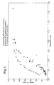
- the present invention offers solutions to these shortcomings by minimising the number of process steps required to manufacture the screens, offering a wide array of materials that can be used to make the screen providing much higher aspect ratios and by achieving a high AOV at lower thicknesses and thereby increasing screen definition at a given AOV (see Figure 1).
- a process for producing a light diffusing sheet material comprising the steps of:
- the first and second materials may be materials which are solid at room temperature and which, when heated, will become fluid at an elevated temperature such as thermoplastic polymeric materials, materials which are fluid at room temperature but are capable of subsequent setting or polymerisation to a solid form, (either thermoplastic or thermoset) and combinations of these materials.
- optically clear material means material which has a light transmission of at least 80%, preferably 85%, more preferably 90%.
- the first and second optically clear materials have a viscosity ratio that is between 0.05 and 10 at the processing temperature and the first optically clear material is dispersed in the second optically clear material by melt mixing or compounding, for example in a simple extruder, to form a mixture in which the first material is present as a multiplicity of discrete globules.
- the viscosity ratio is defined as the viscosity of the matrix material divided by the viscosity of the dispersed phase material).
- the step of forming a film from the mixture includes hardening the film, and where appropriate, orienting the material, preferably as an integral part of the sheet forming process, to create asymmetrical optical properties.
- said second material is thermoplastic and is caused to harden by cooling.
- at least said second material is caused or allowed to harden by chemical action, for example by polymerisation, which may be induced chemically or physically (for example by exposure to UV or other ionising radiation or by heating).
- the invention further relates to sheet diffusers made according to any of the processes disclosed herein.
- the dispersion of the first material in the second is effected by vigorous mechanical mixing, beating, compounding, or mastication, for example utilising the mechanical mixing effect afforded by the screw or screws in a conventional screw extruder
- the final size or final minimum size of the globules of said first material at the end of this mechanical mixing is, the applicants have found, also a function of the relative viscosity of the two materials.
- the ratio of the viscosity of the second (matrix) material to the first (dispersed) material should be in the range 0.05 to 10, (more preferably greater than 1).
- the minimum globule size readily obtainable is also a function of the interfacial surface energy between the two materials, (which may be modified by the use of surfactants).
- the two optically clear materials have an interfacial surface energy between 1 x 10 -4 and 1 x 10 -2 N/m at the processing temperature.
- the sheet material In order to render the sheet material asymmetric as regards its light-diffusing properties (e.g. so that it scatters light more widely horizontally than vertically) it is preferably oriented, e.g. by physically stretching before it has become solid or in the course of extruding the sheet or film.
- the first and second optically clear materials may be materials which are liquid at room temperature but which can solidify as a result of chemical action or of subsequent processing.
- the materials may be monomers, prepolymers or mixtures of the components of two-part curing systems, the mixing, dispersing and subsequent casting or extrusion of the mixture to form a filin taking place before such setting or solidification has taken place.
- the material is to be oriented, for asymmetry, this may, for example, be achieved by extruding or pouring the material, at the appropriate stage in the setting process, onto a moving belt or web travelling somewhat faster than the extrusion rate, whereby the material is oriented in such pouring or extrusion but sets before the dispersed globules, which have become elongated as a result of such extrusion or pouring, are able to revert to a spherical shape.
- the first and second materials may be thermoplastic polymers or copolymers which are solid at room temperature but which will become fluid when heated. where the materials selected are thermoplastic the mixing step will be carried out at elevated temperature.
- one material may be thermoplastic and the other thermosetting, for example, where reaction rates at respective melt temperature permit, for example.
- Materials which are liquid at room temperature which may be used in the present invention include, but are not limited to, monomers and prepolymers of the general classification esters, acrylics, urethanes, siloxanes and the like, or two-component systems including epoxies, polyesters and polyurethanes.
- Materials which may be used which are solid at room temperature include, but are not limited to, polymers and copolymers, such as polyolefins, polyesters, polyamides or polyamide copolymers, acrylics, silicone polymers and elastomers, polystyrene, polycarbonate, cellulose acetate, cellulose acetate butyrate. In general, materials which are amorphous rather than crystalline in the solid state may provide advantageous results.
- the first and second optically clear materials may be selected from ethylene and propylene polymers and copolymers, polystyrenes and acrylics, provided, of course, that the first and second materials are immiscible.
- the materials set out above may be used either as the second (matrix) material or as the first (dispersed) material, provided, of course, that the two materials selected for any particular embodiment are immiscible and have different refractive indices. It will be understood that the tendency of a specific material to become either the matrix or the dispersed phase during the mixing process depends on a number of factors including the proportions of the individual components. It will be recognized that this comment will apply to materials which are fluid at room temperature when mixed at elevated temperature with materials which are solid at room temperature. For example, siloxane resins including elastomers, fluids at room temperature can be "injected" into polyethylene or similar polymers during extrusion, or during mixing (e.g.
- silicone elastomers can be blended with a minor proportion of polyethylene and subsequently cured so that the polyethylene particles become the dispersed phase. In some instances the silicone elastomer can be of sufficiently low molecular weight before and during the mixing process to be regarded as fluid.
- thermoplastics materials solid at room temperature and thus having a melting point, or glass transition temperature T g above room temperature
- the use of one or more optically clear materials which have a T g lower than room temperature are however contemplated to be within the scope of the present disclosure.
- materials, such as glass and, notably, thermoplastic polymeric materials do not change suddenly from a solid to a liquid phase at a specific temperature and thus have no specific melting point, but rather become progressively less viscous over a range of temperatures.
- T g glass transition temperature
- Liquid/liquid combinations that is materials combinations which are liquid at room temperature, can be mixed as described at room temperature such that one disperses within the other as small droplets. The mixture can then cast as a thin filin onto a convenient substrate, typically polyester, whereafter at least the matrix material is converted to a substantially solid film by, for example, polymerisation (or condensation) using heat, UV, election beam or other curing method. The resulting film may remain attached to the substrate or subsequently be separated from it.
- Additional processing steps may be incorporated.
- the material which forms the light diffusing particles in the liquid phase is a solid at room temperature
- This enables a uniform dispersion to be created quickly and can reduce the time and energy required to produce particles of the required final size.
- the filin forming step may incorporate or b followed by a process which "distorts" the generally spherical shape of the dispersed phase to be ellipsoidal or otherwise elongate and in this way create asymmetric optical properties.
- orientation for example by force or by drawing the fluid material through a die orifice or other restraint.
- the material must be converted to a solid state, typically by cooling or polymerisation, to ensure that the asymmetry is not lost due to relaxation phenomena.
- the material may be subsequently oriented as described in US Patent No. 5473454.
- This disclosure demonstrates making light diffusing films by creating a dispersion of light scattering optically clear particles in an optically clear matrix during mixing of the constituent components of the diffuser in the fluid phase and then forming a filin or sheet by, e.g. extrusion or casting, from which a screen suitable for displaying images projected thereupon may be constructed.
- the respective light dispersing and matrix components are chosen by their respective viscosities, interfacial surface energies, and refractive index differential.
- optically clear material when the ratio of the viscosity of a second (matrix) optically clear material to first (forming light dispersing particles), optically clear material is between 0.05 and 10, the first optically clear material can readily be dispersed or broken up into particles of a desired diameter during mixing or mastication of the two optically clear materials while in the fluid phase.
- the second optically clear material forms the matrix or binder for the light diffusing screen, and, as such, is desirably durable stable, self-supporting, and allows lamination to other materials, such as reflective backings.
- suitable optically clear materials are optically clear acrylics such as optically clear polymethylmethacrylates; optically clear polystyrenes; optically clear polypropylenes; optically clear "tenite" organic acid cellulose esters, e.g. cellulose acetate butyrates, cellulose acetate, and cellulose acetate propionate and optically clear polycarbonates.
- optically clear polypropylene/polyethylene copolymers may be used.
- the first optically clear materials dispersed in the second as small particulate or ellipsoidal "lenses", directs the light where desired.
- the shape of the lenses, their size and the ⁇ n (refractive index difference) between the first and second optically clear materials determine the redirection of the light as well as the gain of the screen comprising the light diffusing sheet material.
- suitable first optically clear material are also application dependent, but may be optically clear acrylics such as optically clear polymethylmethacrylates (e.g. Zeneca XB-1223); optically clear polystyrenes; optically clear polypropylenes; optically clear "tenite” organic acid cellulose esters, e.g.
- cellulose acetate butyrates cellulose acetate, and cellulose acetate propionate
- optically clear polycarbonates may be used.
- matrix and dispersed phase materials are interchangeable.
- optically clear materials which form the matrix and dispersed particles are discussed herein generally as homogeneous materials, each could also be heterogeneous, i.e. mixtures of optically clear materials, chosen to meet the requirements disclosed herein, i.e. immiscibility, differential viscosity, refractive index, etc.
- compatibilizers known in the art may be used, such as KRATON (Shell) block copolymers.
- the compatibilizer is added at less than 5% by weight based on the total weight of the mixture.
- These compatibilizers may be polymers or copolymers.
- a copolymer is herein defined as a polymer created from more than one monomer.
- the compatibilizer has moieties chemically compatible with each of the components of the mixture to which it is added.
- a matrix of ethylene ethylacrylate copolymer and a dispersed phase of polystyrene may be compatibilized by the addition of a small amount of a styrene/acrylic copolymer compatibilizer.
- Other compatibilizers which may be used include zinc stereate and olefin waxes.
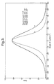
- angle of view refers to the range of viewing angles of observers relative to a diffusing screen or a rear projection screen over which the apparent brightness of the screen is within 50% or more of the apparent brightness to an observer viewing the screen at tight angles assuming that the light incident on the screen is incident along the normal to the screen. This figure is often referred to as “full width half maximum” or “fwhm”.
- angle of view was measured by illuminating a small area of the screen material by a laser beam (although some other collimated light beam may be used) directed normally to the plane of the screen and measuring the light reflected (or for rear projection screens transmitted) from that small area over a range of angles.
- angle of view for transmission means “angle of view” defined as above for a screen of light-diffusing material illuminated by a projector or the like disposed on the opposite side of the plane of the screen from the observer, i.e.
- angle of view for reflection means “angle of view” defined as above for a screen of light reflective material illuminated by a projector or the like disposed on the same side of the plane of the screen as the observer, i.e. for a front projection screen.
- the particle size and concentration of the dispersed phase in the matrix, as well as the ⁇ n of the two optically clear materials will determine the light diffusive properties of the screen.
- the AOV is found to be directly proportional to the concentration and ⁇ n and inversely proportional to the particle size at the dispersed phase as shown in U.S. Patent No. 5196960. It has been found that ⁇ n values of 0.2 - 0.005 preferably 0.1 - 0.007 provide the desired optical properties.
- the particle size for the dispersed phase ranges from about 1 to 50 ⁇ , preferably 2 to 30 ⁇ , and more preferably 2 to 15 ⁇ . However, for more highly asymmetric materials, oriented particles of larger volume, but having a minor dimension in the range 2 - 10 ⁇ m, are preferred.
- the material is desirably processed via vigorous mixing or mastication of the optically clear material components, at a temperature higher than the T g of the first material.
- Any apparatus capable of providing the proper mixing may be used, for example, Banbury mixer, single screw or twin screw extruder, Hobart mixer etc.
- one embodiment of the invention employs a twin screw extruder to disperse the second optically clear material in the first and produce masterbatch pellets, which may then be loaded into a melting and conveying device (single screw extruder outfitted with a die) to produce a light diffusing sheet material.
- a single screw extruder with a cavity transfer mixer is utilised to both mix and extrude the resins in one single process.
- the first and second optically clear materials are processed using a single screw extruder outfitted with a cavity transfer mixer and a slot die to disperse the second optically clear material in the first, and extrude the melt into a sheet form all in a single step.
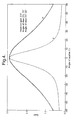
- the sheet emerging from the sheet die is processed onto a take up roll operating at a faster rate than the speed at which the sheet emerges from the sheet die, thereby stretching the sheet in the machine direction and imparting asymmetry to the particles of the first optically clear material dispersed in the matrix (second optically clear material) to result in a high horizontal AOV light diffuser with a high gain and a lower vertical AOV (see Figure 4).
- An alternative to sheet extrusion and orientation to create an asymmetric material is to extrude the material as a tube and expand the tube to a large diameter by differential pressure which, in conjunction with haul-off ratio, enables an optimum of radial and longitudinal orientation to be achieved. Subsequent!y the tube is slot to form a sheet of material with asymmetric optical properties but, by comparison with the more conventional sheet process, no edge effects exist.
- Figure 1 demonstrates the advantages of light diffusing materials according to the present disclosure (data points are obtained from measurements of material as shown in Table 2, below), in comparison to the PLEX-L material. It can be seen that the optical performance of the present materials is superior to the PLEX-L material, although the latter contains 40% dispersed particles, compared to the materials of Examples 4 and 5 (containing 20% or 30% dispersed particles).
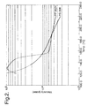
- Figure 2 illustrates a favourable embodiment in which optically clear polypropylene (PP9524 (Exxon Chemical)) is used as the host or matrix material and optically clear polystyrene (Huntsman 208) is used as the dispersed phase.
- PP9524 polypropylene - abbreviated herein as "PP”
- PS polystyrene
- the viscosity ratio of the two materials is 0.8.
- the minor component the polystyrene
- the size of the spherical particles will vary depending on the concentration of the dispersed phase as well as the viscosity ratio, and to some extent the process conditions. The higher the concentration and the lower the viscosity ratio, the higher the size of the dispersed phase particles. It will be understood from Figure 2 that the viscosity ratio can be changed by varying the temperature.
- the ratio of viscosity of matrix to viscosity of dispersed phase is the measured value of interest.
- a viscosity ratio of about 0.3 produces roughly 1 - 2 micron spherical particles (globules), as the minimum readily obtainable by mechanical mixing, when the concentration is 10% dispersed phase and 3 - 4 micron spherical particles, as the corresponding minimum, for a 20% dispersed phase.
- Reducing the viscosity ratio to 0.1 roughly doubles the minimum readily obtainable size of the spherical particles (globules) while increasing the viscosity ratio to 2.0 allows submicron (i.e. less than 1 x 10 -6 m diameter) spherical particles for similar concentrations.
- Light diffusing sheet material in accordance with this disclosure was made as follows. Escorene PP9524 polypropylene (Exxon Chemical) in pellet form (“PP") and crystal polystyrene 208 (Huntsman Chemical Corporation), also in pellet form (“PS”), were added in volumetric proportions of 80% PP and 20% PS to a Leistritz corotating twin screw extruder operating at a barrel temperature of 180°C. Screw speed was set at 50 RPM and feed rate was set at 40RPM. A pelletizer fitted with a water bath was used to convert the extrudate to pellets.
- the pellets were thereafter fed into a Haake Rheocord 9000 outfitted with a single screw extruder and 4 inch die.
- the extruder was run at various RPM to extrude a film onto a take-up roll that was run at various take-up roll speeds.
- the die opening was 0.9 mm.
- the resulting films were measured for vertical angle of view AOV (V), horizontal angle of view AOV (H), gain, average particle size and the average aspect ratio of the particles.
- Table 1 summarises the results obtained for a number of parameters variations to demonstrate the beneficial light dispersing properties of materials made using the methods disclosed herein.
- Light diffusing sheet material in accordance with this disclosure was made as follows. Exact Polyethylene 3024 (Exxon Chemical) in pellet form (“PE”) and crystal polystyrene 208 (Huntsman Chemical Corporation), also in pellet form (“PS”), were added in volumetric proportions of 80% PP and 20% PS to a Leistritz corotating twin screw extruder operating at a barrel temperature of 180°C. Screw speed was set at 50 RPM and feed rate was set at 40RPM. A pelletizer fitted with a water bath was used to convert the extrudate to pellets.
- the pellets were thereafter fed into a Haake Rheocord 9000 outfitted with a single screw extruder with a 4 inch wide die.
- the extruder was run at various RPM to extrude a film onto a take-up roll that was run at various take-up roll speeds.
- the die opening was 0.9 mm.
- the resulting films were measured for vertical AOV, horizontal AOV, gain, average particle size and the average aspect ratio of the particles. Table 2 summarises the results obtained with variation of a number of parameters, to demonstrate the beneficial light dispersing properties of material made using the methods disclosed herein.
- Light diffusing sheet material in accordance with thus disclosure was made as follows. Escorene PP9524 polypropylene (Exxon Chemical) in pellet form (“PP") and Tenite Butyrate 575 (Eastman Chemical Company), also in pellet form (“TB”), were added in volumetric proportions of 90% PP and 10% TB to a Leistritz corotating twin screw extruder operating at a barrel temperature of 180°C. Screw speed was set at 50RPM and feed rate was set at 40RPM. A pelletizer fitted with a water bath was used to convert the extrudate to pellets.
- the pellets were thereafter fed into a Haake Rheocord 9000 outfitted with a single screw extruder and 4 inch die.
- the extruder was run at various RPM to extrude a film onto a take-up roll that was run at various take-up roll speeds.
- the die opening was 0.9 mm.
- the resulting films were measured for vertical AOV, horizontal AOV, gain, average particle size and the average aspect ratio of the particles. Table 3 summarises the results obtained for a number of parameters variation to demonstrate the beneficial light dispersing properties of materials made using the methods disclosed herein.
- Light diffusing materials in which polypropylene formed the matrix material with polystyrene as the disposed phase were produced as follows: Escorene polypropylene PP9524 was compounded in bulk with Crystal polystyrene 207 (Huntsman) in the ratio 70:30 in a Leistritz twin screw extruder as described in Example 1.
- Pellets from this process were extruded into sheet thin a 2" single screw Francis Shaw extruder fitted with a 16" sheet die with a die gap of 1mm.
- the resulting sheet was oriented by varying the haul-off conditions.
- the haul-off equipment consisted of a 3-roll stack with independent temperature and speed controls and separately controlled nip rolls. Orientation could be carried out both above and slight below the tg of the matrix material.
- the average size of the light-diffusing particles in the finished product may be 1 to 50 ⁇ , preferably 2 to 30 ⁇ , more preferably 2 to 15 ⁇ . Still more preferably the average particle size is greater than or equal to 5 ⁇ , for example 5 to 30 ⁇ , more preferably 5 to 15 ⁇ .
- the difference ⁇ n, between the refractive index of the first material and the refractive index of the second material may be 0.2 or more, preferably 0.1 or more, although values of An as low as 0.005 may be useful.
Abstract
Description
| System | Screw Speed, RPM | Take-up Roll RPM | Film Thickness, cm | Average Particle Size µm | Aspect Ratio | AOV Horiz. | AOV Vert. | Gain |
| PP/PS | 25 | 7 | 0.00540 | - | 50 | 68 | 28 | 2.8 |
| 25 | 28 | 0.00057 | 1.211 | 2.943 | 14.5 | 6 | 32.7 | |
| 50 | 7 | 0.02650 | 2.920 | 2.143 | 58.5 | 29 | 2.9 | |
| 50 | 28 | 0.00326 | 0.733 | 1.778 | 68 | 28 | 2.8 | |
| 100 | 7 | 0.03730 | 1.074 | 1.939 | 95 | 75 | 0.8 | |
| 100 | 28 | 0.01370 | - | 100 | 74.5 | 14 | 3.3 |
| System | Screw Speed RPM | Take-up Roll RPM | Film Thickness cm | Average Particle Size µm | Aspect Ratio | AOV Horiz. | AOV Vert. | Gain |
| PE/PS | 25 | 7 | 0.02159 | 1.434 | 1.206 | 74 | 66 | 1.4 |
| 50 | 7 | 0.03719 | 1.242 | 1.229 | 95 | 96 | 0.7 | |
| 50 | 7 | 0.03103 | 1.226 | 1.317 | 93 | 95 | 0.7 | |
| 50 | 28 | 00.01060 | 0.984 | 1.652 | 98 | 60 | 4.9 | |
| 50 | 28 | 0.00976 | 1.245 | 1.327 | 102 | 70 | 4.4 | |
| 100 | 7 | 0.04775 | 1.001 | 2.064 | 97 | 95 | 0.7 | |
| 100 | 7 | 0.03556 | 1.096 | 2.079 | 93 | 92 | 0.7 | |
| 100 | 28 | 0.01702 | 1.010 | 2.278 | 85 | 66 | 1.1 | |
| 100 | 28 | 0.01427 | 0.905 | 1.764 | 92 | 77 | 0.9 |
| System | Screw Speed RPM | Take-up Roll RPM | Film Thickness cm | Average Particle Size µm | Aspect Ratio | AOV Horiz. | AOV Vert. | Gain |
| PP/TB | 25 | 7 | 0.00277 | 2.159 | 1.758 | 8 | 9 | 135.0 |
| 25 | 28 | - | 1.001 | 1.834 | 7 | 11 | 124.2 | |
| 50 | 7 | 0.02036 | 1.65 | 1.332 | 9 | 13 | 145.5 | |
| 50 | 28 | 0.00288 | - | - | 7 | 11 | 111.7 | |
| 100 | 7 | 0.02745 | 1.455 | 1.515 | 7 | 13 | 32.4 | |
| 100 | 28 | 0.01283 | 0.87 | 1.989 | 9 | 11 | 119.2 |
| Film | Thickness | Draw Ratio | AOV (H) | AOV (V) | | Draw Type | |
| 1 | 0.17mm | 5.9 | 70 | 22 | 2.9 | Above | |
| 2 | 0.69mm | 1.5 | 120 | 116 | 0.6 | Above Tg | |
| 3 | 0.25mm | 4.0 | 90 | 42 | 1.6 | Above and below Tg | |
| 4 | 0.26mm | 3.8 | 94 | 42 | 1.6 | Above Tg | |
| 5 | 0.36mm | 2.8 | 112 | 80 | 1.0 | Above Tg |
| Sample | Polystyrene % | Thickness mm | AOV(H) | AOV (V) | |
| 1 | 21 | 1.47 | 124 | 124 | 0.48 |
| 2 | 21 | 0.37 | 99 | 64 | 1 04 |
| 3 | 21 | 0.28 | 84 | 39 | 1.57 |
| 4 | 21 | 0.15 | 50 | 16 | 5.72 |
| 5 | 30 | 0.77 | 121 | 116 | 0.55 |
| 6 | 30 | 0.47 | 113 | 84 | 0.76 |
| 7 | 30 | 0.40 | 108 | 63 | ().93 |
| 8 | 30 | 0.30 | 96 | 34 | 1.49 |
| 9 | 30 | 0.24 | 83 | 22 | 2.32 |
| 10 | 30 | 0.18 | 66 | 14 | 4.20 |
| 11 | 30 | 0.18 | 60 | 10 | 5.62 |
| 12 | 30 | 0.13 | 40 | 6 | 12.73 |
Claims (22)
- A process for producing a light diffusing sheet material comprising the steps of:(a) selecting a first optically clear material and a second optically clear material which are both fluid at a predetermined processing temperature and have different refractive indices, said materials being immiscible in their fluid state,(b) mechanically mixing said materials at said processing temperature so as to disperse the first material in the second material whereby said first material is present as a dipersion of discrete globules in said second material,(c) forming a film from said mixture, and(d) causing or allowing the film, or at least said second material, to solidify so that said globules form light-dispersing particles.
- A process according to claim 1 wherein at least said second material is caused or allowed to harden by chemical action, for example by polymerisation, which may be induced chemically or physically (for example by exposure to UV or other ionising radiation or by heating).
- A process according to claim 1 wherein at least said second material is a thermoplastics which is solid at ambient temperature and wherein said processing temperature is above the melting point or glass transition temperature (Tg) of the thermoplastics.
- A process according to any preceding claim wherein at least said second material is a thermosetting or polymerisable material and wherein said film-forming step comprises casting or extruding the mixture, whilst fluid or still fluid, into or onto a support and allowing or causing it to set.
- A process according to claim 1, wherein said first and second materials have a viscosity ratio between 0.05 and 10 as measured at the processing temperature.
- A process according to any preceding claim including orienting said film to create asymmetric optical properties.
- The process of claim 6 in which the angle of view of the material before the orientation process is at least 60°.
- The process of claim I wherein said film forming step comprises extruding said mixture through a sheet die.
- The process of claim I wherein said film is extruded using a tube die.
- The process of claims 2 or 3 further comprising the step of stretching said film as it exits said die in order to orient the filin.
- The process of claim 1 wherein the average particle size of said light dispersing particles is from 1 to 50µ.
- The process of claim 1 wherein the average particle size of said light dispersing particles is from about 2 to 30µ.
- The process of claim 1 wherein the average particle size of said light dispersing particles is from about 2 to 15µ.
- The process of claim 7 wherein said sheet is stretched in the machine direction by winding said sheet on a take-up roll operating faster than the speed at which the sheet exits from said die.
- The process of claim 8 in which the tube formed is oriented by a combination of differential pressure and haul-off rate.
- The process of claim 1 wherein said film forming step further comprises orienting said dispersed globules of said first material in the machine direction by extruding said mixture through a die.
- The process of claim 1 wherein said dispersing step is accomplished by using a twin-screw extruder in the production of masterbatch pellets; said masterbatch pellets being subsequently processed into sheet form using a single screw extruder to melt, convey, and extrude the melt into said sheet form.
- The process of claim 1 in which processing aids are incorporated in the mixture.
- The process of claim 17 in which the processing aids are polymers or copolymers.
- The process of any of claims 1 to 14 in which one of said materials comprises a polyolefin and the other of said materials comprises polystyrene.
- A light diffusing sheet material made by the process of claim 1.
- The light diffusing material made by the process of claim 6 in which the asymmetry after the orientation process is at least 2:1.
Applications Claiming Priority (2)
| Application Number | Priority Date | Filing Date | Title |
|---|---|---|---|
| US3109696P | 1996-11-14 | 1996-11-14 | |
| US31096P | 1996-11-14 |
Publications (2)
| Publication Number | Publication Date |
|---|---|
| EP0843203A1 true EP0843203A1 (en) | 1998-05-20 |
| EP0843203B1 EP0843203B1 (en) | 2004-05-26 |
Family
ID=21857639
Family Applications (1)
| Application Number | Title | Priority Date | Filing Date |
|---|---|---|---|
| EP97309025A Expired - Lifetime EP0843203B1 (en) | 1996-11-14 | 1997-11-10 | Optical diffusers obtained by melt mixing of incompatible materials |
Country Status (4)
| Country | Link |
|---|---|
| US (1) | US5932342A (en) |
| EP (1) | EP0843203B1 (en) |
| JP (1) | JPH10274704A (en) |
| DE (1) | DE69729260D1 (en) |
Cited By (3)
| Publication number | Priority date | Publication date | Assignee | Title |
|---|---|---|---|---|
| WO2000068712A1 (en) * | 1999-05-11 | 2000-11-16 | Microsharp Corporation Limited | High contrast screen material |
| WO2001084192A1 (en) * | 2000-05-03 | 2001-11-08 | Microsharp Corporation Limited | Reflective light diffuser |
| WO2003077026A1 (en) * | 2002-03-08 | 2003-09-18 | Yupo Corporation | Screen |
Families Citing this family (37)
| Publication number | Priority date | Publication date | Assignee | Title |
|---|---|---|---|---|
| US6483612B2 (en) | 1998-04-15 | 2002-11-19 | Duke University | Projection screen apparatus including holographic optical element |
| US20030206342A1 (en) * | 1993-05-12 | 2003-11-06 | Bright View Technologies, Inc. | Micro-lens array based light transmission screen |
| US6788460B2 (en) * | 1998-04-15 | 2004-09-07 | Duke University | Projection screen apparatus |
| US6123877A (en) * | 1994-12-28 | 2000-09-26 | Nashua Corporation | Asymmetric light diffusing material |
| US6346311B1 (en) | 1997-09-10 | 2002-02-12 | Nashua Corporation | Projection screen material and methods of manufacture |
| US6816306B2 (en) * | 1998-04-15 | 2004-11-09 | Bright View Technologies Inc. | Micro-lens array based light transmitting screen with high resolution and low imaging artifacts |
| US6967779B2 (en) * | 1998-04-15 | 2005-11-22 | Bright View Technologies, Inc. | Micro-lens array with precisely aligned aperture mask and methods of producing same |
| US6829087B2 (en) * | 1998-04-15 | 2004-12-07 | Bright View Technologies, Inc. | Micro-lens array based light transmitting screen with tunable gain |
| US6369944B1 (en) | 1999-07-12 | 2002-04-09 | Nashua Corporation | Diffuser-coated projection screen element and method of manufacture |
| WO2001022129A1 (en) | 1999-09-20 | 2001-03-29 | 3M Innovative Properties Company | Optical films having at least one particle-containing layer |
| TWI299419B (en) * | 2000-05-31 | 2008-08-01 | Nitto Denko Corp | Liquid crystal cell substrate and liquid crystal displays |
| US6665118B2 (en) * | 2000-08-30 | 2003-12-16 | Matsushita Electric Industrial Co., Ltd. | Rear-projection screen and rear-projection image display |
| WO2002039184A1 (en) * | 2000-11-10 | 2002-05-16 | Durand Technology Limited | Optical recording materials |
| US6535333B1 (en) | 2000-11-21 | 2003-03-18 | 3M Innovative Properties Company | Optical system with reduced color shift |
| KR100421002B1 (en) * | 2001-03-07 | 2004-03-03 | 삼성전자주식회사 | Reflection type projection screen |
| WO2002103416A1 (en) * | 2001-06-14 | 2002-12-27 | Skc Co., Ltd. | The light-diffusing film and composition for the same |
| US6939014B1 (en) * | 2001-12-31 | 2005-09-06 | Jenmar Visual Systems, Inc. | Liquid transmissive filter having anisotropic properties and method of fabrication |
| JP2008508557A (en) * | 2004-07-29 | 2008-03-21 | ルーミン・オズ株式会社 | Optical display device with asymmetric field of view |
| WO2006020583A2 (en) * | 2004-08-10 | 2006-02-23 | Fusion Optix, Inc. | Imaging material with improved contrast |
| WO2006031545A1 (en) * | 2004-09-09 | 2006-03-23 | Fusion Optix, Inc. | Enhanced lcd backlight |
| US7453636B2 (en) * | 2004-09-13 | 2008-11-18 | Fusion Optix Inc. | High contrast optical path corrected screen |
| US7431489B2 (en) | 2004-11-17 | 2008-10-07 | Fusion Optix Inc. | Enhanced light fixture |
| US8308075B2 (en) | 2005-04-19 | 2012-11-13 | Kamterter Products, Llc | Systems for the control and use of fluids and particles |
| US20090135345A1 (en) * | 2005-12-12 | 2009-05-28 | Takatoshi Yajima | Polarizing Plate Protective Film, Film Producing Method, Polarizing Plate, and Liquid Crystal Display |
| US7829626B2 (en) * | 2006-03-15 | 2010-11-09 | Rohm And Haas Company | Aqueous compositions comprising polymeric duller particle |
| JP2009538516A (en) | 2006-05-25 | 2009-11-05 | アイ2アイシー コーポレイション | Extraction of light with a preferred radiation pattern from a light emitting medium |
| US7784954B1 (en) | 2006-07-25 | 2010-08-31 | Fusion Optix, Inc. | Polarization sensitive light homogenizer |
| US7722224B1 (en) | 2006-12-15 | 2010-05-25 | Fusion Optix, Inc. | Illuminating device incorporating a high clarity scattering layer |
| US7991257B1 (en) | 2007-05-16 | 2011-08-02 | Fusion Optix, Inc. | Method of manufacturing an optical composite |
| US8721152B2 (en) * | 2009-05-01 | 2014-05-13 | Abl Ip Holding Llc | Light emitting devices and applications thereof |
| US8398292B2 (en) * | 2010-01-15 | 2013-03-19 | Chi Lin Technology Co., Ltd. | Optical unit and light guide plate and ink thereof |
| JP2012058582A (en) * | 2010-09-10 | 2012-03-22 | Gunze Ltd | Manufacturing method of light diffusing film |
| JP6260536B2 (en) * | 2012-09-12 | 2018-01-17 | ソニー株式会社 | Image display device |
| WO2014176143A1 (en) * | 2013-04-22 | 2014-10-30 | Veerag Mehta | Toughening and flexibilizing thermoplastic and thermoset polymers |
| TWI763735B (en) | 2016-12-09 | 2022-05-11 | 美商道康寧公司 | Composition, light diffuser and device formed thereby, and related methods |
| US10125439B2 (en) * | 2017-02-02 | 2018-11-13 | Douglas J. Bailey | Flexible translucent to transparent fireproof composite material |
| JP6860427B2 (en) * | 2017-06-02 | 2021-04-14 | 株式会社ユポ・コーポレーション | Light diffusing film, shooting diffuser, and display diffusing plate |
Citations (4)
| Publication number | Priority date | Publication date | Assignee | Title |
|---|---|---|---|---|
| EP0265956A2 (en) * | 1986-10-29 | 1988-05-04 | Hitachi Medical Corporation | Method for correcting position deviation due to static magnetic field change in NMR imaging device |
| US4983016A (en) * | 1989-01-30 | 1991-01-08 | Matsushita Electric Industrial Co., Ltd. | Transmission projection screen and method of manufacturing the same |
| JPH05113606A (en) * | 1991-10-23 | 1993-05-07 | Sumitomo Chem Co Ltd | Reflection type screen |
| WO1995012631A1 (en) * | 1993-11-01 | 1995-05-11 | E.I. Du Pont De Nemours And Company | Multicomponent pellets of barrier resin and compatibilizer for making laminar articles |
Family Cites Families (89)
| Publication number | Priority date | Publication date | Assignee | Title |
|---|---|---|---|---|
| FR864139A (en) * | 1939-03-18 | 1941-04-19 | Kodak Pathe | projection screen |
| US2443918A (en) * | 1944-06-19 | 1948-06-22 | Rhone Poulenc Sa | Light-diffusing cellulose acetate compositions |
| US2584441A (en) * | 1946-05-03 | 1952-02-05 | Rca Corp | Viewing screen |
| US2901337A (en) * | 1956-07-31 | 1959-08-25 | Union Carbide Corp | Abrasive articles and method of making the same |
| US3437405A (en) * | 1964-08-27 | 1969-04-08 | Owens Corning Fiberglass Corp | Light control panel |
| US3674736A (en) * | 1969-04-15 | 1972-07-04 | Nat Distillers Chem Corp | Process for the preparation of pigmented polymer powders of controlled particle shape and size and size distribution and product |
| US3646174A (en) * | 1969-12-12 | 1972-02-29 | Susquehanna Corp | Process for making spheroidal agglomerates |
| US3679451A (en) * | 1970-02-13 | 1972-07-25 | Marks Polarized Corp | Nonglare coating for surfaces of tv tubes and the like and such coated surfaces |
| DE2010115A1 (en) * | 1970-03-04 | 1971-09-16 | Farbenfabriken Bayer Ag, 5090 Leverkusen | Process for the production of micro-granules |
| US3992486A (en) * | 1971-02-09 | 1976-11-16 | Rohm And Haas Company | Process for altering appearance of polymer by incorporating therein crosslinked particulate polymers prepared by endopolymerization |
| US3751135A (en) * | 1971-06-25 | 1973-08-07 | E Clausen | Rear projection screen |
| DE2225578C3 (en) * | 1972-05-26 | 1978-08-10 | Roehm Gmbh, 6100 Darmstadt | Molding compound for the production of light-diffusing moldings |
| US4174883A (en) * | 1974-01-29 | 1979-11-20 | Canon Kabushiki Kaisha | Rear projection screen |
| JPS5184635A (en) * | 1975-01-24 | 1976-07-24 | Fuji Photo Film Co Ltd | |
| US4105292A (en) * | 1975-09-02 | 1978-08-08 | Minnesota Mining And Manufacturing Company | Optical element to assure a minimum spacing |
| US4166255A (en) * | 1976-06-14 | 1979-08-28 | Minnesota Mining And Manufacturing Company | Hybrid corneal contact lens |
| US4114983A (en) * | 1977-02-18 | 1978-09-19 | Minnesota Mining And Manufacturing Company | Polymeric optical element having antireflecting surface |
| JPS5936837B2 (en) * | 1977-04-05 | 1984-09-06 | 株式会社東芝 | Optical semiconductor device |
| US4140369A (en) * | 1977-04-11 | 1979-02-20 | Massachusetts Institute Of Technology | Efficient light diffuser |
| US4452508A (en) * | 1977-06-28 | 1984-06-05 | British Telecommunications | Graded index optical fibres |
| US4165153A (en) * | 1978-04-25 | 1979-08-21 | Polaroid Corporation | Translucent screen |
| FR2454135A1 (en) * | 1979-04-13 | 1980-11-07 | Suisse Horlogerie | DIFFUSING SURFACE STRUCTURE FOR AN INFORMATION DISPLAY LIGHT GUIDE |
| US4285889A (en) * | 1979-12-26 | 1981-08-25 | Hughes Aircraft Company | Method for fabricating thin panel illuminator |
| JPS56106237A (en) * | 1980-01-29 | 1981-08-24 | Matsushita Electric Ind Co Ltd | Transmissive screen and its manufacture |
| AU523917B2 (en) * | 1980-04-08 | 1982-08-19 | Matsushita Electric Industrial Co., Ltd. | Rear projection screen for a colour television projector |
| DE3018449C2 (en) * | 1980-05-14 | 1983-01-05 | Dr. Johannes Heidenhain Gmbh, 8225 Traunreut | Projection screen device |
| JPS5781254A (en) * | 1980-11-10 | 1982-05-21 | Toshiba Corp | Transmission type projector |
| US4377616A (en) * | 1981-12-30 | 1983-03-22 | Mobil Oil Corporation | Lustrous satin appearing, opaque film compositions and method of preparing same |
| US4506045A (en) * | 1982-10-02 | 1985-03-19 | Bayer Aktiengesellschaft | Cellulose ester-aliphatic polycarbonate thermoplastic moulding compositions |
| JPS6040134A (en) * | 1983-08-13 | 1985-03-02 | Showa Denko Kk | Preparation of fine particle of polyamide resin |
| JPS6155684A (en) * | 1984-08-27 | 1986-03-20 | 三菱レイヨン株式会社 | Light diffuser |
| US4717496A (en) * | 1984-12-03 | 1988-01-05 | Giulini Chemie Gmbh | Stiffening material with melt-adhesive properties |
| US4606609A (en) * | 1985-08-12 | 1986-08-19 | Hong Sung K | Projection screen |
| US4843129A (en) * | 1985-12-27 | 1989-06-27 | Exxon Research & Engineering Company | Elastomer-plastic blends |
| US4923649A (en) * | 1986-03-06 | 1990-05-08 | Phillips Petroleum Company | Pelletizing polymers |
| US4679900A (en) * | 1986-06-05 | 1987-07-14 | North American Philips Corporation | Bulk diffuser for a projection television screen |
| US4763985A (en) * | 1986-08-01 | 1988-08-16 | Minnesota Mining And Manufacturing Company | Retroreflective sheet with enhanced brightness |
| US4863646A (en) * | 1986-10-23 | 1989-09-05 | Shinto Paint Co., Ltd. | Method of producing fine particles of thermoplastic resin |
| US5237004A (en) * | 1986-11-18 | 1993-08-17 | Rohm And Haas Company | Thermoplastic and thermoset polymer compositions |
| CA1337104C (en) * | 1986-11-18 | 1995-09-26 | William James Work | Light-scattering thermoplastic polymers |
| US4767675A (en) * | 1986-11-21 | 1988-08-30 | Cyr Patricia A | Oriented opaque films containing alkenylaromatic polymers |
| US4822856A (en) * | 1987-02-18 | 1989-04-18 | The Dow Chemical Company | Preparation of polymeric blend stock |
| US4876296A (en) * | 1987-04-27 | 1989-10-24 | Olin Corporation | Method and composition for controlled thickening of thermosetting resins using microencapsulated thickeners |
| GB8711005D0 (en) * | 1987-05-09 | 1987-06-10 | British Petroleum Co Plc | Chemical process |
| DE3877829T2 (en) * | 1987-06-01 | 1993-07-29 | Sar Realisations Ltd | PRESENTATION SYSTEM WITH TRANSPARENT SCREEN AND METHOD FOR THE PRODUCTION THEREOF. |
| US4814377A (en) * | 1987-09-04 | 1989-03-21 | Union Carbide Corporation | Process for incorporating high molecular weight olefin based copolymers into a polymer matrix |
| US5278532A (en) * | 1987-09-14 | 1994-01-11 | Hughes Aircraft Company | Automotive instrument virtual image display |
| US4767186A (en) * | 1987-10-06 | 1988-08-30 | North American Philips Consumer Electronics Corp. | Front projection screen with rear light concentrating lens array |
| IT1223262B (en) * | 1987-12-11 | 1990-09-19 | Himont Inc | ELASTIC PLASTIC COMPOSITIONS AND PROCEDURE FOR THEIR PREPARATION |
| US5300942A (en) * | 1987-12-31 | 1994-04-05 | Projectavision Incorporated | High efficiency light valve projection system with decreased perception of spaces between pixels and/or hines |
| US5012274A (en) * | 1987-12-31 | 1991-04-30 | Eugene Dolgoff | Active matrix LCD image projection system |
| JPH01210942A (en) * | 1988-02-19 | 1989-08-24 | Pioneer Electron Corp | Screen for rear side projection type projection television |
| ES2046299T3 (en) * | 1988-05-18 | 1994-02-01 | Rohm And Haas Company | THERMOSTABLE AND THERMOPLASTIC POLYMERIC COMPOSITIONS. |
| US5016950A (en) * | 1988-07-05 | 1991-05-21 | Hughes Aircraft Company | Full-color zero-order suppressed diffraction optics diffusing screen/louver filter laminate |
| US4960314A (en) * | 1988-07-05 | 1990-10-02 | Hughes Aircraft Company | Diffraction optics diffusing screen laminate for full color on-axis viewing |
| DK160593C (en) * | 1988-09-28 | 1991-09-09 | Dainippon Printing Co Ltd | A rear projection screen |
| DK687288A (en) * | 1988-12-09 | 1990-06-10 | Dainippon Printing Co Ltd | A rear projection screen |
| US5011244A (en) * | 1988-12-16 | 1991-04-30 | Hughes Aircraft Company | Holographic full color data retrieval and projection system |
| KR920008058B1 (en) * | 1989-01-28 | 1992-09-22 | 주식회사 금성사 | Front projection screen |
| US5279689A (en) * | 1989-06-30 | 1994-01-18 | E. I. Du Pont De Nemours And Company | Method for replicating holographic optical elements |
| EP0406761A3 (en) * | 1989-07-04 | 1993-01-20 | Mitsubishi Kasei Vinyl Company | Image protecting film and image protecting method |
| US5040870A (en) * | 1989-10-13 | 1991-08-20 | Sumitomo Chemical Company, Limited | Screen for projection |
| ATE155897T1 (en) * | 1990-05-21 | 1997-08-15 | Nashua Corp | MICROLENS DISPLAYS MADE OF PHOTOPOLYMERIZABLE MATERIALS AND METHOD FOR THE PRODUCTION THEREOF |
| CA2042452A1 (en) * | 1990-05-25 | 1991-11-26 | Loren D. Trabert | Modified acrylic capstock |
| EP0464499A3 (en) * | 1990-06-22 | 1992-04-15 | Sumitomo Chemical Company, Limited | Anisotropic light-scattering material, method for producing the same and lenticular lens for projection tv screen |
| WO1992004400A1 (en) * | 1990-09-04 | 1992-03-19 | Ohno Research And Development Laboratories Co., Ltd. | Plastic optical member having light diffusing layer on surface, and light quantity control member |
| DE69132092T2 (en) * | 1990-10-29 | 2001-01-11 | Kuraray Co | Lenticular leaf-shaped lens |
| US5292783A (en) * | 1990-11-30 | 1994-03-08 | Eastman Kodak Company | Aliphatic-aromatic copolyesters and cellulose ester/polymer blends |
| US5178955A (en) * | 1990-12-17 | 1993-01-12 | Allied-Signal Inc. | Polymeric anti-reflection coatings and coated articles |
| US5111337A (en) * | 1991-01-04 | 1992-05-05 | Eugene Martinez | Enhanced contrast, maximum gain front and rear projection screens |
| JPH04249237A (en) * | 1991-01-18 | 1992-09-04 | Rohm & Haas Co | Method of concealing scratch or defect on back projection screen surface |
| FR2673576B1 (en) * | 1991-03-08 | 1993-06-18 | Essilor Int | PROCESS FOR OBTAINING AN ARTICLE OF TRANSPARENT POLYMER MATERIAL WITH GRADIENT OF REFRACTION INDEX. |
| US5179440A (en) * | 1991-05-13 | 1993-01-12 | Hughes Aircraft Company | Rear projection facetted dome |
| US5198267A (en) * | 1991-09-20 | 1993-03-30 | Allied-Signal Inc. | Fluoropolymer blend anti-reflection coatings and coated articles |
| US5118579A (en) * | 1991-09-20 | 1992-06-02 | Allied-Signal Inc. | Fluoropolymer blends for coatings |
| US5139879A (en) * | 1991-09-20 | 1992-08-18 | Allied-Signal Inc. | Fluoropolymer blend anti-reflection coatings and coated articles |
| US5188777A (en) * | 1991-11-05 | 1993-02-23 | Mobil Oil Corporation | Opaque film and method for its preparation |
| US5349503A (en) * | 1991-12-31 | 1994-09-20 | At&T Bell Laboratories | Illuminated transparent display with microtextured back reflector |
| US5245454A (en) * | 1991-12-31 | 1993-09-14 | At&T Bell Laboratories | Lcd display with microtextured back reflector and method for making same |
| US5307205A (en) * | 1992-03-20 | 1994-04-26 | Rohm And Haas Company | Bilayer rear projection screens |
| US5357372A (en) * | 1992-04-07 | 1994-10-18 | Hughes Aircraft Company | Ultra-compact, wide field of view virtual image display optical system |
| US5548670A (en) * | 1992-11-27 | 1996-08-20 | Koike; Yasuhiro | Light-scattering light-guiding device |
| US5457572A (en) * | 1992-12-17 | 1995-10-10 | Kuraray Co., Ltd. | Rear-projection screen |
| EP0615150A3 (en) * | 1993-03-08 | 1994-12-21 | Corning Inc | Cover glass for LCD panel. |
| JP3298215B2 (en) * | 1993-03-26 | 2002-07-02 | 住友化学工業株式会社 | Method for producing polymer particles having refractive index distribution |
| EP0627638A1 (en) * | 1993-06-02 | 1994-12-07 | Hughes Aircraft Company | Elliptical diffuser |
| JPH071428U (en) * | 1993-06-04 | 1995-01-10 | 株式会社エンプラス | Surface light source |
| DE4327464A1 (en) * | 1993-08-16 | 1995-02-23 | Roehm Gmbh | Process for the production of monodisperse poly (meth) acrylate particles |
| US5472649A (en) * | 1994-04-13 | 1995-12-05 | Eastman Chemical Company | Method for preparing powder coating compositions having improved particle properties |
-
1997
- 1997-11-03 US US08/963,654 patent/US5932342A/en not_active Expired - Lifetime
- 1997-11-10 DE DE69729260T patent/DE69729260D1/en not_active Expired - Lifetime
- 1997-11-10 EP EP97309025A patent/EP0843203B1/en not_active Expired - Lifetime
- 1997-11-14 JP JP9313468A patent/JPH10274704A/en active Pending
Patent Citations (4)
| Publication number | Priority date | Publication date | Assignee | Title |
|---|---|---|---|---|
| EP0265956A2 (en) * | 1986-10-29 | 1988-05-04 | Hitachi Medical Corporation | Method for correcting position deviation due to static magnetic field change in NMR imaging device |
| US4983016A (en) * | 1989-01-30 | 1991-01-08 | Matsushita Electric Industrial Co., Ltd. | Transmission projection screen and method of manufacturing the same |
| JPH05113606A (en) * | 1991-10-23 | 1993-05-07 | Sumitomo Chem Co Ltd | Reflection type screen |
| WO1995012631A1 (en) * | 1993-11-01 | 1995-05-11 | E.I. Du Pont De Nemours And Company | Multicomponent pellets of barrier resin and compatibilizer for making laminar articles |
Non-Patent Citations (1)
| Title |
|---|
| DATABASE WPI Section Ch Week 9323, Derwent World Patents Index; Class A32, AN 93-185565, XP002057957 * |
Cited By (7)
| Publication number | Priority date | Publication date | Assignee | Title |
|---|---|---|---|---|
| WO2000068712A1 (en) * | 1999-05-11 | 2000-11-16 | Microsharp Corporation Limited | High contrast screen material |
| GB2365540A (en) * | 1999-05-11 | 2002-02-20 | Microsharp Corp Ltd | High contrast screen material |
| GB2365540B (en) * | 1999-05-11 | 2004-01-21 | Microsharp Corp Ltd | High contrast screen material |
| US6747796B1 (en) | 1999-05-11 | 2004-06-08 | Michael G. L. Dorling | High contrast screen material |
| WO2001084192A1 (en) * | 2000-05-03 | 2001-11-08 | Microsharp Corporation Limited | Reflective light diffuser |
| GB2380268A (en) * | 2000-05-03 | 2003-04-02 | Microsharp Corp Ltd | Reflective light diffuser |
| WO2003077026A1 (en) * | 2002-03-08 | 2003-09-18 | Yupo Corporation | Screen |
Also Published As
| Publication number | Publication date |
|---|---|
| US5932342A (en) | 1999-08-03 |
| JPH10274704A (en) | 1998-10-13 |
| EP0843203B1 (en) | 2004-05-26 |
| DE69729260D1 (en) | 2004-07-01 |
Similar Documents
| Publication | Publication Date | Title |
|---|---|---|
| EP0843203B1 (en) | Optical diffusers obtained by melt mixing of incompatible materials | |
| US5548670A (en) | Light-scattering light-guiding device | |
| US6582783B2 (en) | Laminated films | |
| KR100693991B1 (en) | Anisotropic Light-Scattering Film | |
| EP0464499A2 (en) | Anisotropic light-scattering material, method for producing the same and lenticular lens for projection tv screen | |
| US6747796B1 (en) | High contrast screen material | |
| US7766493B2 (en) | Optical display device with asymmetric viewing area | |
| JP2010015133A (en) | Optical diffuser film with linear domain of varying diffusion | |
| KR20020070381A (en) | Light guide and method for producing transparent thermoplastic resin composition for light guide | |
| JP2003508822A (en) | Rear projection screen using birefringent optical film for asymmetric light scattering | |
| WO2016093181A1 (en) | Transparent sheet, transparent screen comprising same, and image projector including same | |
| WO2016104055A1 (en) | Transparent film, transparent screen provided with same, and image projection device provided with same | |
| EP0456518B1 (en) | Projection screen and method for producing the same | |
| JPH04314522A (en) | Anisotropic light scattering material, its manufacture and lenticular lens for screen of projection television | |
| JPH06123802A (en) | Transmission type light diffusion plate and its production | |
| JP3013551B2 (en) | Reflective screen | |
| US6369944B1 (en) | Diffuser-coated projection screen element and method of manufacture | |
| JP4777441B2 (en) | Transmission screen | |
| US20110019279A1 (en) | Light diffusing film and process for producing the light diffusing film | |
| JP3851380B2 (en) | Light diffusing sheet and manufacturing method thereof | |
| JP2891705B2 (en) | Lenticular lens sheet for transmission screen and method of manufacturing the same | |
| KR20080003696A (en) | Extruded polymer sheets with high dimensional stability for anisotropy light scattering | |
| JPH0234307A (en) | Manufacture of polymer containing powder additive | |
| JPH04328148A (en) | Light-diffusing sheet-like article | |
| JPH1020403A (en) | Projection screen |
Legal Events
| Date | Code | Title | Description |
|---|---|---|---|
| PUAI | Public reference made under article 153(3) epc to a published international application that has entered the european phase |
Free format text: ORIGINAL CODE: 0009012 |
|
| AK | Designated contracting states |
Kind code of ref document: A1 Designated state(s): DE FR GB NL |
|
| AX | Request for extension of the european patent |
Free format text: AL;LT;LV;MK;RO;SI |
|
| 17P | Request for examination filed |
Effective date: 19981118 |
|
| AKX | Designation fees paid |
Free format text: DE FR GB NL |
|
| RBV | Designated contracting states (corrected) |
Designated state(s): DE FR GB NL |
|
| 17Q | First examination report despatched |
Effective date: 20000620 |
|
| GRAP | Despatch of communication of intention to grant a patent |
Free format text: ORIGINAL CODE: EPIDOSNIGR1 |
|
| GRAS | Grant fee paid |
Free format text: ORIGINAL CODE: EPIDOSNIGR3 |
|
| GRAA | (expected) grant |
Free format text: ORIGINAL CODE: 0009210 |
|
| AK | Designated contracting states |
Kind code of ref document: B1 Designated state(s): DE FR GB NL |
|
| PG25 | Lapsed in a contracting state [announced via postgrant information from national office to epo] |
Ref country code: NL Free format text: LAPSE BECAUSE OF FAILURE TO SUBMIT A TRANSLATION OF THE DESCRIPTION OR TO PAY THE FEE WITHIN THE PRESCRIBED TIME-LIMIT Effective date: 20040526 Ref country code: FR Free format text: LAPSE BECAUSE OF NON-PAYMENT OF DUE FEES Effective date: 20040526 |
|
| REG | Reference to a national code |
Ref country code: GB Ref legal event code: FG4D |
|
| RAP2 | Party data changed (patent owner data changed or rights of a patent transferred) |
Owner name: NASHUA IMAGING SUPPLIES (UK) LIMITED Owner name: NASHUA CORPORATION |
|
| REF | Corresponds to: |
Ref document number: 69729260 Country of ref document: DE Date of ref document: 20040701 Kind code of ref document: P |
|
| PG25 | Lapsed in a contracting state [announced via postgrant information from national office to epo] |
Ref country code: DE Free format text: LAPSE BECAUSE OF FAILURE TO SUBMIT A TRANSLATION OF THE DESCRIPTION OR TO PAY THE FEE WITHIN THE PRESCRIBED TIME-LIMIT Effective date: 20040827 |
|
| NLT2 | Nl: modifications (of names), taken from the european patent patent bulletin |
Owner name: NASHUA CORPORATION EN NASHUA IMAGING SUPPLIES (UK) |
|
| NLV1 | Nl: lapsed or annulled due to failure to fulfill the requirements of art. 29p and 29m of the patents act | ||
| PLBE | No opposition filed within time limit |
Free format text: ORIGINAL CODE: 0009261 |
|
| STAA | Information on the status of an ep patent application or granted ep patent |
Free format text: STATUS: NO OPPOSITION FILED WITHIN TIME LIMIT |
|
| 26N | No opposition filed |
Effective date: 20050301 |
|
| EN | Fr: translation not filed | ||
| REG | Reference to a national code |
Ref country code: GB Ref legal event code: 732E |
|
| REG | Reference to a national code |
Ref country code: GB Ref legal event code: 732E |
|
| PGFP | Annual fee paid to national office [announced via postgrant information from national office to epo] |
Ref country code: GB Payment date: 20151229 Year of fee payment: 19 |
|
| GBPC | Gb: european patent ceased through non-payment of renewal fee |
Effective date: 20161110 |
|
| PG25 | Lapsed in a contracting state [announced via postgrant information from national office to epo] |
Ref country code: GB Free format text: LAPSE BECAUSE OF NON-PAYMENT OF DUE FEES Effective date: 20161110 |