BACKGROUND OF THE INVENTION
a) Field of the Invention
The present invention relates to a card reader which handles a magnetic card or an IC card
and the like.
b) Description of the Related Art
In a conventional card reader, an IC or magnetic card on which data are stored is held in
the thickness direction by a pair of rollers, at least one of which is driven by a motor and the like,
thereby transferring the card to the driving path. In the magnetic card reader which is disclosed
in Japanese Patent Laid Open No. H5-12498, for example, a magnetic card is held by three pairs
of rollers arranged in the driving direction thereby transferring the magnetic card. When data
recording / reproduction is performed, a magnetic strip formed on the magnetic card is moved
with respect to the magnetic head. In a card reader, the size of a card insertion slot is somewhat
larger than the card, therefore, the card is not always inserted straight. To resolve the problem in
a card reader of the conventional technology, the distance by which the card is transferred is set
long such that the magnetic card which is inserted at a slanted angle or in an askew manner is
straightened before it reaches the magnetic head. However, providing a long path is undesirable
as it prevents the production of reduced-size card readers.
When using a magnetic card in the card reader, one or both sides of the card normally is
formed with a magnetic strip. The magnetic information on the magnetic strip is recorded
/reproduced by the magnetic heads formed opposite each other across the card driving path. With
the magnetic heads on the sides of the driving path, each of the magnetic heads are designed to be
pressed by a compression coil spring such that the magnetic heads are projected to transfer the
force to a magnetic card. However, if a warped card is driven, the magnetic head deviates from
the base position due to the warping of the card. Upon removal of the card, the head deviation is
maintained. If a magnetic card is inserted into a slot while the magnetic head is deviated from its
original position, the end of the card contacts a side of the magnetic head, thereby affecting the
smooth driving of the card.
In addition, current card readers may be used to read both magnetic cards and IC cards.
When recording to or reading from an IC card, the IC terminal formed on one side of the card is
contacted by the card reader, and the IC contact block of the card reader is moved by means of a
specific actuator (solenoid). However, a mechanism, independent from the driving mechanism for
transferring the IC card, to drive the IC contact block is required, thus increasing the number of
components, cost and size of the card reader. Also, when the IC contact block is designed to be
lowered along with the card movement, the load during the IC card transfer increases, thus
causing the card to jam. Further, a card reader may be designed such that the magnetic head is
given the capability to record/reproduce magnetic data, and if the IC contact block is lowered
during such recording reproducing, data recording/ reproduction may be degraded.
OBJECTS OF THE INVENTION
Therefore, it is an object of the present invention to provide a card reader which can be
reduced in size by reducing the distance over which the card is transferred.
Another object of the present invention is to provide a card reader which can read a
warped card.
A further object of the present invention is to provide a card reader, when an IC card is
handled by the above card reader, the overall card reader can be made compact by driving a card
transfer means and an IC contact transfer means by a single motor.**
SUMMARY OF THE INVENTION
In accordance with one embodiment of the present invention, a card reader is comprised
of a card insertion slot through which a card is inserted, a card transferring device which transfers
the inserted card from the insertion slot along a card driving path to a reading device (e.g., a
magnetic head), and pressing means disposed between the card insertion slot and the reading
device for pressing against one edge of the card so that the opposite edge of the card is pressed
against a card driving reference plane.
As an aspect of the invention, when an IC card having an IC terminal is inserted in the
card reader, an IC contact block is provided to make contact with the IC terminal so that the data
stored in the IC card can be read therefrom. The card reader further includes a contact block
moving device which moves the IC contact block towards and away from the IC card, and
wherein a load torque required to move the IC contact block to contacting position (with the IC
card) is set larger than a load torque required for transferring the IC card by the card transfer
means; and is set smaller than a load torque required for transferring the IC card when the
position of the IC card is limited. The card reader further comprises a driving force switching
mechanism for switching a rotational force of the motor to either the card transfer means or the
contact block moving device depending on which device has the smaller load torque.
In accordance with another embodiment of the present invention, the card reader is
comprised of a card insertion slot through which a card is inserted, a card transferring device
which transfers the inserted card from the insertion slot along a card driving path, a magnetic head
located above a read position for reading data stored on a magnetic strip of the card, bias means
for biasing the magnetic head in a direction towards the surface of the card, and head movement
limiting means for establishing a predetermined minimum distance of the magnetic head above the
card driving path when the card is not located at the read position, and the head movement
limiting means does not establish the predetermined minimum distance when the card is located at
the read position.
As an aspect of this embodiment, two opposing magnetic heads are provided for reading
magnetic strips located on opposite sides of the card, and a second bias means is provided for
biasing the second magnetic head towards the card such that the first and second bias means
provide biases in opposite directions towards one another, and the head movement limiting means
forces the first and second magnetic heads into respective neutral positions above and below the
card driving path only when the card is not located at the read position.
BRIEF DESCRIPTION OF THE DRAWINGS
The following detailed description, given by way of example and not intended to limit the
present invention solely thereto, will best be appreciated in conjunction with the accompanying
drawings, wherein like reference numerals denote like elements and parts.
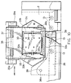
Fig. 1 is a plan cross section showing a card transfer mechanism of a card reader of the
present invention.
Fig. 2 is a vertical cross section detailing the card pressure mechanism of the card reader
shown in Fig.1.
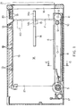
Fig. 3 is a vertical cross section showing a card driving reference plane of the card reader
shown in Fig. 1.
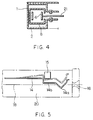
Fig. 4. Is a IV-IV cross section of a card reader shown in Fig. 1.
Fig. 5 is a diagram showing a positional relationship between the optical sensor and plate
spring of the card reader shown in Fig. 1.
Fig. 6 is a plan view showing a head support mechanism of a card reader of the present
invention.
Fig. 7 is a plan cross section showing the overall card reader shown in Fig. 6.
Fig. 8 is a vertical cross section showing a head support mechanism cut out at III-III
shown in Fig. 6.
Fig. 9 is a side view of the head support mechanism shown in Fig. 8.
Fig. 10 is a bottom view of showing the support mechanism of the lower magnetic head
shown in Fig. 8.
Fig. 11 is a vertical cross section showing a state in which two magnetic heads are
displaced.
Fig. 12 is a side view showing another embodiment for the head support mechanism of
two magnetic heads.
Fig. 13 is a plan view showing another embodiment for the position guiding member for a
magnetic head.
Fig. 14 is a side view of Fig. 13.
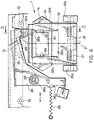
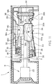
Fig. 15 is an overall configuration including the IC contact block of a card reader of the
present invention.
Fig. 16 is a magnified diagram for an IC contact block moving means shown in Fig. 15.
Fig. 17 is a schematic configuration describing the IC contact block movement shown in
Fig. 16.
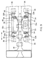
Fig. 18 is a extended diagram of Fig. 15, in which gears convert the driving forces of a
card reader shown in Fig. 15.
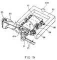
Fig. 19 is a descriptive diagram showing another embodiment for the IC contact block
movement.
DETAILED DESCRIPTION OF THE PREFERRED EMBODIMENTS
Referring now to the drawings, Figs. 1 - 3 show embodiments of the card reader of the
present invention. The card reader in these embodiments is for a magnetic card, which is driven
by a motor to transfer the magnetic card inserted from the card insertion slot to record /
reproduce data on the magnetic card by means of a magnetic head. The magnetic head can be
reproduction specific or capable of both recording and reproducing.
Case 20 of the card reader is mounted with upper guiding frame 1 and lower guiding
frame 2 (Fig. 3) which are made of a composite comprising sheet metal and molded. Card driving
path 18 and driving reference plane 19 are formed in case 20. Magnetic head 40 is arranged in the
middle of card driving path 18. The support mechanism and the like for this magnetic head 40 are
described herein.
A pressing member in accordance with the present invention is located between card
insertion slot 16 on case 20 and magnetic head 40, such pressing member contacting the side
surface of card 21 so that card 21 presses against driving reference plane 19. In the disclosed
embodiment, the pressing member is rotating member driven by, for example, driving motor 3
(See Fig. 15) which starts driving upon insertion of card 21. As shown in Fig. 1, the pressing
member is a flat surface of belt 6 with teeth. Belt 6 is held between transmission pulley 11 with
gear, which is arranged between card insertion slot 16 and magnetic head 40 to press the side
surface of card 21 against the driving reference plane 19 side. Card 21 is transferred on the flat
surface of belt 6, thereby providing a card transfer means, and driving pulley 5 with a gear, which
is rotatably driven by driving motor 3.
Transmission pulley 11 is rotatably supported by shaft 9 at the end of pulley support arm 8
which is rotatably supported by shaft 7. Driving pulley 5 is positioned in the vicinity of the base
of pulley support arm 8 and movably mounted on case 20. Between transmission pulley 11 and
driving pulley 5, transfer pulley 12 with teeth, which transfer card 21 via belt 6 with teeth, is
formed such that transfer pulley 12 dependently rotates via the teeth on belt 6 to press the side
surface of card 21 with the flat surface of belt 6 with teeth against the card driving reference plane
19 side. That is, transfer pulley 12, arranged in the vicinity of transmission pulley 11, is rotatably
supported by shaft 10, which is mounted onto pulley support arm 8. Because belt 6 is engaged
with each of the pulleys 5, 11, and 12 with its teeth, which prevents the pulleys from slipping on
the belt when motor driving force is transmitted. Also, the horizontal cross section of pulley
support arm 8 is shaped in a square with an open side as shown in Fig. 4. Belt 6 is arranged inside
the pulley support arm 8.
As shown in Fig. 5, card 21 is inserted to the slot and plate spring 14 is lifted up, when
photo sensor 15 detects the deformation, thereby moving motor 3. Plate spring 14 is fixed onto
upper guiding flame 1. Projection 14a is projected over card driving pass 18. When card 21 is
inserted into the slot, photo sensor 15 is actuated. Belt 6 is moved as driving pulley 5 is rotated
via a deceleration gear train (described later) by the driving force of motor 3. Card 21 is further
taken in the driving direction on belt 6 as driving pulley 5 is rotated via deceleration gear train
(described later) by the driving force of motor 3. Coil spring 17 is mounted on the base end of
pulley support arm 8. One end of coil spring 17 is mounted on the case 20 side; the other end is
mounted on the base end of pulley support arm 8. Coil spring 17 rotates pulley support arm 8
counterclockwise, in Fig. 1, around shalt 7 so that each of pulleys 11, 12 are projected over card
driving path 18, that is, transmit the force to press the side of card 21 to each of pulleys 11, 12;
as a result, the driving force of belt 6 is transmitted to the left surface (Fig. 1, lower side
surface) of card 21. Card driving reference plane 19 comprises a plurality of rotatable rollers 13.
In other words, card driving reference plane 19 is structured such that (the outer surface of)
rotatable rollers 13 is slightly projected from a surface formed by a side mold portion of each of
guiding frames 1, 2.
How the card reader operates card driving is described. When card 21 is inserted into
card insertion slot 16, card 21 contacts projection 14a of plate spring 14 to push up actuator 14b
of a photo sensor. When photo sensor 15 detects the movement of actuator 14b, motor 3 is
activated to rotate belt 6 counterclockwise, as shown in Fig. 1, via a deceleration gear train and
pulley 5; that is, to rotate belt 6 in the direction in which card 21 is taken into the card reader.
When card 21 is inserted via card insertion as far as where pulley 11 is, card 21 is taken into the
card reader by the driving force from belt 6.
When the tip of card 21 taken into the card reader reaches point E indicated with the
double dotted line in Fig. 1, card 21 is positioned nearly parallel with card driving reference plane
19 by two pairs of rollers 13 on card insertion slot 16 side and pulley 11, and are taken into the
card reader straight to magnetic head 40. When the magnetic strip on card 21 touches magnetic
head 40, the magnetic head reads / writes the data on the magnetic strip. Transfer pulley 12 is
arranged such that it projects slightly more than transmission pulley 11, thereby pulley 12 acts as
the main feeder for the card transfer on belt 6 during the read /write mode of magnetic head 40.
Instead of slightly more projecting transfer pulley 12 than transmission pulley 11, pulleys 11, 12
may be arranged in parallel in the card transfer direction.
When the read / write mode of head 40 is completed, card 21 at point F indicated with
double dotted line in Fig. 1, card 21 is displaced from pulley 11. Card 21 is pressed against card
driving reference plane 19 side only with pulley 12. Then, motor 3 is driven reversely to eject
card 21 by rotating belt 6 clockwise as shown in Fig. 1.
In the above embodiment, the rotational force of motor 3 is transmitted to drive pulley 5
to rotate belt 6, thus each of the pulleys 11, 12 are rotated. However, pulley 11 or pulley 12 may
be rotated directly by motor 3. Also, in the above embodiment, a plurality of rollers 13 are
provided on card driving reference plane 19 to construct a row of rollers. The row of rollers may
be replaced with a belt which moves as a card is driven. In addition, each roller 13 may be
omitted and a mold surface may contact a card.
The magnetic head support mechanism in accordance with the present invention will now
be described. Referring to Figs. 6 - 11, card 21 is pushed in the card reader such that it projects
within card driving path 18. At the same time, the card reader includes magnetic heads 40, 50,
which are supported such that they can move in the direction orthogonal to the card surface which
conforms to the wave/warps of card 21, and a limiting lever, which acts as a limiting member in
accordance with the present invention..
Limiting lever 36 is positioned at the limited position (indicated with a solid line in Fig. 6)
at which the amount of projection of the magnetic heads 40, 50 over card driving path 18 when
card 21 is ejected to the outside of the card reader and does not contact magnetic heads 40, 50.
Limiting lever 36 retreats from the limited position (see double dotted line in Fig. 6) when card 21
is inserted into the card reader and contacts magnetic heads 40, 50.
The card reader, as shown in Figs. 7 and 8, includes upper and lower guiding frames 1 and
2 which form card driving path 18, magnetic heads 40, 50, which are formed on the sides of the
direction perpendicular to the card surface on card driving path 18, a card feeding mechanism by
means of belt 6 arranged along one end of card driving path 18, and an insertion detecting sensor
110, which detects the fact that card 2 is inserted into the end of the slot.
Head windows 1a, 2a are formed on upper and lower guiding frames 1, 2 where magnetic
heads are arranged such that magnetic heads 40, 50 can be exposed to card driving path 18.
Magnetic heads 40, 50 are arranged on the upper and lower sides of card driving path 18
as shown in Figs. 8 and 9. In this embodiment, upper head 40 is for a 1-track magnetic strip;
lower head 50 is for a 3-track magnetic strip. However, the present invention is not limited to
these. Different types of magnetic heads can be used to meet the different specifications of
magnetic strips, of course. Also, it is acceptable that each magnetic head 40, 50 performs at least
one of the recording or reproducing functions.
Upper and lower magnetic heads 40, 50 are supported by upper and lower support plates
32, 33, as shown in Figs. 6 and 10, which are movable around axis 34 and shaped in square whose
longer side is laid along the card driving direction. Upper support plate 32 is arranged opposite
card driving path 18 of upper guiding frame 1; lower support plate 33 is arranged opposite card
driving path 18 of lower guiding frame 2. In the middle of upper and lower support plates 32, 33,
head windows 32a, 33a constructed with through holes. At both ends of each head windows 32a,
33a, flanges 32b, 33b projects above the side of card driving path 18. Upper and lower magnetic
heads 40, 50 are movably mounted on flanges 32b, 33b of upper and lower support plates 32, 33
around shaft 34.
Upper and lower support plates 32, 33 are movably supported by upper and lower guiding
frames 1 and 2 around shalt 35, 35 which are shaped in square with a long side laid along the card
driving direction. Both ends of shalt 35, 35 are supported by shalt support blocks 35a, 35a
molded onto upper and lower guiding frames 1, 2. Shaft 35, 35 is wound with spring 37 made of
a coil spring. Spring 37, 37 transmits force from support plates 32, 33 such that magnetic heads
50 project into card driving path 18. Therefore, when external force does not operate on upper
and lower support plates 32, 33 and upper and lower magnetic beads 40, 50, the head surfaces of
upper and lower magnetic heads 40, 50 contact each other within card driving path 18 or face
each other at a distance via contact limiting means which upper and lower magnetic heads 40, 50
are equipped with. In accordance with the present invention, it is not required that spring 37 is so
strong as to correct the waves or warps of a card by pressing against the magnetic heads. Instead,
it is sufficient that spring 37 "drag" the card (i.e., follows the curvature of the card) by contacting
the card with its head surface as the card is driven. This configuration reduces friction between
the head surface and card 21.
Opposite of where springs 37, 37 of upper and lower support plates 32, 33 are installed,
lever bearings 32c, 33c, which are curved in the direction away from card driving path 18, are
formed. Lever bearings 32c, 33c limit the movement position for support plates 32, 33 by
contacting limiting lever 36. In the present invention, the projection position of magnetic heads
40, 50 to card driving path 18 is limited by lever bearings 32c, 33c of support plates 32, 33.
However, the projection position to card driving path 18 can be limited by magnetic heads 40, 50
directly contacting limiting lever 36.
As shown in Fig. 6, limiting lever 36 is arranged at the side of upper support plate 32 of
upper guiding frame 1. Limiting lever 36 is nearly L shape and comprises support portion 36a,
which is the center of the curved movement of 36, a contact roller 38, which is mounted at one
end as a contact portion, limiting portion 36b, which contact lever bearings 32c, 33c formed in the
vicinity of contact roller 38; and a spring mounting portion 36c, which is formed on the other end.
Support portion 36a is movably mounted onto shalt 39 which is perpendicular to the card surface
and mounted on upper frame 1.
Contact roller 38, which is formed on limiting lever 36, is shaped such that its longer side
is vertical to the card surface, comes in and out with respect to card driving path 18 as limiting
lever 36 moves. Limiting portions 36b, 36b are positioned opposite card driving path 18 of upper
and lower guiding frames 1, 2 and are shaped such that they are curved closer to card driving path
18. Therefore, limiting portion 36b, 36b can contact lever bearings 32c, 33c of each support plate
32, 33 as limiting lever 36 moves.
Also, one end of limiting spring 26, which is made of heli coil spring as a transmission
member, is mounted at spring mounting portion 36c of limiting lever 36. The other end of
limiting spring 26 is mounted on the upper guiding frame 1 at a point closer the away from the
slot end. Limiting spring 26 rotates limiting lever 36 clockwise as shown in Figs. 6 and 7 so that
contact roller is projected into the card driving path; also, by pressing limiting portions 36b, 36b
against lever bearings 32c, 33c, the projection position of magnetic heads 40, 50 is limited at the
center of card driving path 18. At this projection position, it is ideal that magnetic heads 40, 50
are somewhat distanced while the end surfaces of magnetic heads 40, 50 are close together.
How card reader record in reproduces on card 21 is described herein.
Before card 21 is inserted, as shown in Figs. 6 and 7, limiting lever 36 is rotated clockwise
by limiting spring 26. Contact roller 38 projects to card driving path 18 and limiting portions 36b,
36b are pressed against lever bearings 32c, 33c. For this reason, as shown in Fig. 8, upper and
lower support plates 32, 33 cannot move with respect to card driving path 18, and at the same
time, the head surfaces of magnetic heads 40, 50 are positioned where the head surfaces and the
card surface correspond to each other, that is, the neutral position.
By inserting card 21, a card transfer mechanism is driven as previously described and card
21 is taken further on belt 6, which is a card transfer means.
Next, the tip of card 21 contacts contact roller 38. By this, contact roller 38 retreats from
card driving path 18 by resisting limiting spring 26. Limiting portions 36b, 36b are distanced from
support plates 32, 33, thus movement of support plates 32, 33 are set free.
At the same time, the tip of card 21 contacts the head surfaces of magnetic heads 40, 50.
Therefore, at the projection position of magnetic heads 40, 50, limited at the center of card
driving path 18, the magnet heads are parted in a range which ensures the contact between the
magnetic heads and the card, even when the tips of magnetic heads 40, 50 need to be somewhat
distanced.
Card 21 is guided along the head surface to enter the gap between upper and lower
magnetic heads 40, 50, thus expanding heads 40, 50 while the card is being driven. At this time,
magnetic heads 40, 50 are pressed against card 21 via springs 37, 37, thus ensuring the contact
between the magnetic strip and the head surface. Magnetic data are read / written when the
magnetic strip and the head surface contact while card 21 is being driven.
The present embodiment describes an example in that the head surfaces contact each other
at the neutral position before card 21 is inserted. The embodiment is not limited to this. As
shown in Fig. 12, the tips of support plates 32, 33 can be extended to form head contact limiting
portions 32d, 33d such that head contact limiting portions 32d, 33d contact before card 21 is
inserted. A contact limiting means can be formed for maintaining magnetic heads 40, 50 at a
neutral position at which heads do not contact each other.
As described above, if head contact limiting portions 32d, 33d are designed to keep their
tips away form each other, even in the state card 21 is not present, when the card is off the
magnetic heads, which is provided with a small area of contact for head contact limiting portions
32d, 33d, which makes them extremely easier to return to the neutral position from the upper or
lower position of card driving path 18, by limiting lever 36.
Next, when card 21 reaches the end of the path, the tip of card 21 is detected by insertion
detection sensor 110 as shown in Fig. 7. By this, the card transfer mechanism is stopped or
reverse rotated to exit card 21. When card 21 is ejected from the card reader, contact roller 38
can project to card driving path 18, thus, moving limiting lever 36 by limiting spring 26. Along
with this operation, limiting portions 36b, 36b are pressed by each support plates 32, 33 to set
magnetic heads 40, 50 to the neutral position.
Note that some cards are warped or curved. When inserting a warped card 21 into the
card reader of this embodiment, magnetic heads 40, 50 move against support plates 32, 33 and
support plates 32, 33 move against frames 1, 2, thus the head surface can conform the card
surface. For this reason, even if a deformed card 21 is used, reading/writing of data can be
performed highly accurately.
Also, as shown in Fig. 11, when deformed card 21 is ejected, magnetic heads 40, 50 may
deviate from the center. This is because the head surfaces contact and are pressed by spring 37,
having the head surfaces abrade each other; the heads keep their deviated positions. However, in
this embodiment, limiting portions 36b, 36b move to contact lever bearings 32c, 33c; this sets
supporting plates 32, 33 and magnetic heads 40, 50 to the center.
Therefore, according to this embodiment, limiting portions 36b, 36b are shaped to curve
closer to card driving path 18; lever bearings 32c, 33c are shaped to curve away from card driving
path 18. Even if support plate 32, 33 are largely deviated from the center, limiting portions 36b,
36b move to press one of the curvatures of lever beatings 32c, 33c with limiting portions 36b, 36b
on one side, support plates 32, 33 can return to the neutral position. With this recovery, magnetic
heads 40, 50 are kept at a distance. The tip of card 21 inserted into the card reader contacts the
side surfaces of magnetic heads 40, 50, thus maintaining a smooth driving of card 21.
As shown in Fig. 11, when the head surfaces of magnetic heads 40, 50 contact each other
and are deviated from the neutral position, the head surfaces of magnetic heads 40, 50 must be
slid in the direction of the longer side of the contact surfaces to retain their neutral positions. As
shown in Fig. 12, the magnetic heads can be returned to their neutral positions extremely easy
using limiting lever 36 if the head surfaces of magnetic heads 40, 50 are set such that they do not
contact while head contact limiting portions 32d, 33d are set to contact, and the area of contact is
made small for head contact limiting portions 32d, 33d.
Also in this embodiment, both magnetic heads 40, 50 can be moved in the yawing and the
card surface direction; they can contact card 21 even more closely; this makes it possible to read /
write magnetic data accurately.
Note that, in the above embodiment, limiting lever 36 is used as a limiting member which
yaws. However, movable lever 125, as shown in Figs. 13 and 14, which is movable in the card
driving direction can be used. In this case, contactingly movable lever 125 comprises contacts
portion 125a which contact the tip of card 21 and limiting portion 125b which enters between the
head surfaces of upper and lower magnetic heads 40, 50. In addition, a limiting spring made of
helicoid spring 26' is attached on a part of contactingly movable lever 125. Note that in this
embodiment, the structure of upper and lower magnetic heads 40, 50 or support plates 32, 33 or
guiding frames 1,2 and the like are the same as the above embodiment, therefore, is not described
herein.
In this embodiment, limiting portion 125b is entered between head surfaces using the force
transmitted from limiting spring 26' to set magnetic heads 40, 50 in the middle. Then, card 21 is
inserted and contact portion 125a is pushed and limiting portion 125b is pushed out of magnetic
heads 40, 50. When card 21 is ejected, limiting portion 125b again enters between magnetic
heads 40, 50 to set them in the center.
Even when a deformed card 21 is used, when card 21 is ejected, limiting porion 125b sets
magnetic heads 40, 50 in the center. Therefore, this embodiment also suggests that magnetic
heads 40, 50 of the present invention in a largely deviated state can smoothly drive the next card
that is inserted. Also, all of the above embodiments have magnetic heads 40, 50 at the sides of
card driving path 18. However, the present invention is not limited to this. Magnetic heads can
be installed only on one side. In this case, nothing will need to be formed opposite of the
magnetic head over card driving path 18, but a pad roller may be arranged thereon.
Next, a card reader with a mechanism for handling an IC card, in which the IC contact
block is lowered in accordance with the present invention, is described.
In Fig. 15, card 21 is transferred from card insertion slot 16 to where data is read/ written
using the rotational (driving) force of motor 3. Data is read/ written by contacting IC contact 610
(See Fig. 17,) which is held by IC contact block 61 formed on an IC terminal exposed manner on
card 21. This embodiment includes a card transfer means by belt 6, which transfers card 21
between card insertion slot 16 and read / write position; and a contact block moving means 60,
which moves IC contact block 61 between the contact position and the retreat position.
The load torque which is required for moving IC contact block 61 to the contact point
with card 21 is set larger than that which is required for moving belt 6, which is the load torque of
transfer means for the transfer of card 21, and is smaller than that which is required when the card
21 is inserted into the read / write position which is the end of its movement. At the same time, a
driving force switching mechanism 70 is formed for transmitting rotational force of motor 3 to the
side where each load torque is smaller.
Note that in this card reader, data is read / written while card 21 is being transferred
between a magnetic strip on card 21 and magnetic heads 40, 50, which are formed in the middle
of card driving path 18, which is made up of lower guiding frame 2 and upper guiding frame 1.
Card transfer means comprises four pulleys 5, 11, 111, 112 and drive belt 6 which is held
by each pulley. Pulley 5 transmits the rotational force of motor 3 which is transmitted from drive
force switching mechanism 70 via gear 49 to drive belt 6. Pulley 11 is mounted at the tip of arm 8
which is rotatable around shaft 9; driving belt 6 is pressed onto one end of card 21 by being
stretched in counterclockwise by spring 17 (See Fig. 1.) Pulleys 111, 112 are mounted at the tip
of rotatable arms 87, 88 around shalt 86. They are pulled by each of springs 89, 90 to press drive
belt 6 against one end of card 21. Drive belt 6 is the same as in the previous embodiment in that it
transfers card 21 from card insertion slot 16 to the read / write position by pressing card 21
against eight rollers 13, which makes a card reference plane.
Contact block moving means 60, as shown in Fig. 16, includes an arm 62, which is
rotatable within a range of predetermined angles, a cam lever 63, which moves IC contact block
61 from the retreat position from card driving path 18 to the contact point with the card, two
return coil springs 64, which return the IC contact block 61 from the contact position to the
retreat position.
Note that the above contact position (position indicated with a double-dotted line in Fig.
17) is where IC contact 610 of IC contact block 61 resiliently contacts the IC terminal exposed on
card 21. The retreat position (position indicated with a solid line in fig. 17) is where IC contact
610 is apart from the IC terminal, which opens a way for transferring card 21.
Two shafts 65 are fitted through IC contact blocks 61. Each shalt 65 supports four pairs
of IC contacts 610 of a resilient spring structure. Sleeve 66 is rotatably fitted onto both ends of
each shalt 65. Each sleeve 66 is inserted into U groove 67 formed on upper guiding frame 1.
Therefore, IC contact block 61 can move only in the depth direction of each U groove, that is in
the direction vertical to the moving direction of card 21.
Around IC contact block 61, that is outside each U groove 67, cam lever 63 is shaped
nearly a rectangle with an open side. Cam lever 63 is held on upper guiding frame 1 in the
transfer direction of card 21 slidably at a predetermined distance. Cam portion 63b is formed at
four places opposite each sleeve 66 of cam lever 63. Therefore, if cam lever 63 slides, each
sleeve 66 is pushed down toward the opening of U grooves as shown in Fig. 17. In other words,
IC contact block 61 is moved to the contact position.
Each return spring 64 is arranged in the state in which they are compressed between
spring base 64a, 64a formed in the center of both ends of IC contact block 61 and upper guiding
frame 1. Therefore, each return spring 64 pushes each sleeve 66 up toward the bottom of each of
the U grooves 67. In other words, if the pressure from cam lever 63 is released, IC contact block
61 is moved to the retreat position.
A long hole 62a is formed in the center of arm 62. Convexity 63b formed on cam lever 63
is inserted into the long hole 62a. Therefore, if arm 62 is rotated around shaft 68, cam lever 63
slides. At the tip surface of arm 62, gear portion 62b is formed. Gear portion 62b is engaged
with a small gear 54 of deceleration gear train 59. Therefore, if second output gear 58 of drive
switch mechanism is rotated, the rotation is transmitted to gear portion 62b via large gear 51, gear
52a, small gear 52b, gear 53, and small gear 54 of deceleration gear train 59. Arm 62 is rotated
by these gears.
In other words, if a rotational force of motor 3 is transmitted to second output gear 58,
arm 62 rotates clockwise in Fig. 15. Cam lever 63 is moved to the contact position by sliding IC
contact block 61. On the other hand, if a rotational force of motor in the refers direction is
transmitted, arm 62 rotates counterclockwise in Fig. 15. Cam lever 63 is returned and IC contact
block 61 is moved to the retreat position.
One end of coil spring 165 is positioned at a predetermined position on arm 62; the other
end of coil spring 165 is mounted on upper guiding frame 1. Coil spring 165 pulls arm 62 in the
direction apart from IC contact block 61. The load torque, which works on contact block
moving means 60, is increased when IC contact block 61 is moved to the contact position; it is
decreased when IC contact block 61 is moved to the retreat position. In other words, the load
torque, which is required to move contact block 61 to the contact position, is set larger than that
is required for transferring card 21 and set smaller than that is required when card 21 is at the read
/write position, which is the end of movement. Also, the load torque which is required for
moving contact block 61 to the retreat position is set smaller than that is required for transferring
card 21 by adjusting the magnitude of force of coil spring 165.
Note that in the vicinity of arm 62, photo sensor 160 is installed. This photo sensor 160
detects the fact that arm 62 is rotated to the contact position with IC contact block 61.
Driving force switching mechanism 70 is a gear connection mechanism including first
output gear 57 and second output gear 58 which transfer the rotational force of motor 3 to
contact block moving means 60. Of the first and second output gears 57, 58, the output gear with
a larger load torque is stopped, thus the output gear with a smaller torque is rotated. This gear
connection mechanism comprises, as shown in Fig. 18, driving force division gear unit 400
arranged relatively rotatably on the same shalt between the first and second output gears 57, 58.
Driving force division gear unit 400 includes driving gear 41, which is rotated by motor 3,
revolving shalt 41a, which is fitted through the eccentric position of driving gear 41 and is
relatively rotatably mounted at the eccentric position, first division gear 42, which is fixed at one
end of revolving shaft 41a; and second division gear 43, which is fixed on the other end of the
revolving shaft 41a.
First division gear 42 is engaged with first output gear 57 side. In other words, it is
acceptable if first division gear 42 is engaged with first output gear 57 directly or indirectly. In
this embodiment, first division gear 42 directly transmits the rotational force for engagement with
first output gear 57. On the other hand, second division gear 43 is engaged with second output
gear 58 side. In other words, it is acceptable that second division gear 43 is engaged with the side
of second output gear 58 directly or indirectly. In this embodiment, second division gear 43
transmits the rotational force for indirect engagement with second output gear 58 via pinion gear
44. Pinion gear 44 is installed relatively rotatably at the eccentric position of drive gear 41 in the
same manner as second division gear 43. Note that in Fig. 18, second output gear 58 and pinion
gear 44 are apart; they are illustrated that way to simplify the drawing. However, they are
engaged in actual use.)
Rotational force of motor 3 is transmitted to drive gear 41 via umbrella gear 45, large gear
46, small gear 47 respectively. If drive gear 41 is rotated, each division gear 42, 43 and pinion
gear 44, which are installed at the eccentric position of drive gear 41, revolve around each output
gear 57, 58. First output gear 57 transmits the rotational force to the card transfer means. It
receives a predetermined load torque when the card reaches the read / write position, that is, the
transfer end position of card 21 as shown in Fig. 15. Also, second output gear 58 transmits the
rotational force to contact block moving means 60. It receives the load torque which is required
for moving contact block 61. The power relationship between each load torque is set by adjusting
the speed ratio of the gear train of the card transfer means side to the contact block moving means
60 side and adjusting the spring force of coil spring 65 of contact block moving means 60. In
other words, the load torque which is required to move contact block 61 is set significantly
smaller than that is required when card 21 is at the read /write position, which is the end of the
path. Note that umbrella gear 45 is fixed onto output shaft of motor 3. Also, large gear 465 and
small gear 47 are a composite gear which rotates integrally.
The operation of the IC card reader will now be described. First, when card 21 is inserted
into card insertion slot 16, the sensor detects card 21, rotating motor 3. The rotational force of
motor 3 is transmitted deceleratingly to drive gear 41 via umbrella gear 45, large gear 46, small
gear 47 respectively. Therefore, each division gear 42, 43 begins to rotate around each output
gear 57, 58.
Now, the load torque which is required to move IC contact block 61 is set larger than that
required for transfer of card 21. In other words, the minimum value for the load torque while IC
contact block 61 moves is larger than the maximum value of the load torque required for transfer
of card 21. Second output get 58 receives a larger load torque than first output gear 57.
For this reason, second output gear 58, which receives a larger load torque, is stopped;
pinion gear 44, which revolves second output gear 58, and second division gear 43 revolve.
Therefore, first division gear 42, which is connected to second division gear 43 by revolving shaft
41a revolves; first output gear 57 which is engaged with first division gear 42 rotates.
In other words, if drive gear 41 rotates and first and second division gears 42, 43 revolve
around first and second output gears 57, 58, of these first and second output gears 57, 58, second
division gear 43, which is engaged with second output gear 58 side and is stopped due to
receiving a larger load torque, revolves. This revolution is transmitted to the other first division
gear 42 via revolving shalt 41a to rotate first output gear 57 which receives a smaller load torque
from first and second output gears 57, 58.
The rotational force of first output gear 57 is transmitted to gear 49 of card transfer
means. It rotate belt 6 by rotating pulley 5 via gear 5a. By doing so, card 21 which is inserted
into card insertion slot 16 is taken into the card reader as card 21 is pressed onto each rollers 13
to be transferred to the read / write position. Card 21 is transferred smoothly while it is
transferred a power relationship between the load torque which is required to move IC contact
block 61 and load torque which transfers card 21 is maintained. The rotational force of motor 3 is
transmitted only to the card transfer means side. In other words, the rotational force is not
transferred to moving means 60 until card 21 is transferred to the read / write position. The card
transfer means is driven only.
On the other hand, if card 21 reaches to the read /write position, which is the end of the
path, card transfer load temporarily increases. It exceeds IC contact block moving load. In other
words, the load torque which is larger than that required for moving IC contact block 61 is
generated on the card transfer means side. For this reason, unlike the above mentioned case, first
output gear 57 receives a larger load torque than second output gear 58. First output gear 57 is
stopped at this time and first division gear 42 which revolves around first output gear 57 revolves.
Therefore, second division gear 43, which is connected to first division gear 42 via revolving shaft
41a revolves, rotating second output gear 58 which is engaged with first division gear 42.
In other words, when drive gear 41 rotates and first and second division gears 42, 43
rotate around first and second output gears 57, 58, of first and second output gears 57, 58, first
division gear 42, which is engaged with the side of first output gear 57, revolves. First output
gear 57 is stopped when receiving a larger load from one of them. This rotation is transmitted to
second division gear 43 via revolving shaft 41a. Second output gear 58, which receives a smaller
load torque from one of first and second output gears is rotated via pinion gear 44.
The rotational force of the second output gear is transmitted to large gear 51 of contact
block moving means 60. Then, it is deceleratingly transmitted to gear 52a, small gear 52b, large
gear 53, and small gear 54 respectively. Arm 62 is driven in this way. Cam lever 63 is slid to
move IC contact block 64 to the contact position with card 21. When photo sensor 66 detects
that IC contact block 64 reached the contact position, that is, arm 62 is moved to a predetermined
position, rotation of motor 3 is stopped. In this state, "detent" torque works on motor 3. Arm 62
will not be retracted by coil spring 165. IC contact block 61 is held at the contact position of card
21.
To complete reading /writing data and to eject card 21, motor 3 is rotated reversely. Now
when card 21 is ejected, coil spring 165 works in returning direction of arm 62. The load torque
which second output gear 58 receives becomes significantly smaller than that which first output
gear 57 does. Therefore, the reversed rotational force is transmitted to contact block moving
means 60 side via second output gear 58. Before card 21 ejection process begins, IC contact
block 61 is moved to the retreat position first.
Note that the fact that the reading / writing of magnetic data is performed while card 21 is
being transferred is the same as conventional technology.
When IC contact block 61 reaches the retreat position, then, the load torque which second
output gear 58 receives becomes significantly larger than that first output gear 57 receives.
Therefore, the reversed rotational force of motor 3 is transmitted to card transfer means side via
first output gear 57 to eject card 21.
Note that in the above description, arm 62 of contact block moving means 60 and cam
lever 63 are independent. They can be integrated, of course.
Also, rotational force between motor 3 and drive force division gear unit 400, between
first output gear 57 and second output gear 58, and between second output gear 58 and arm 62
pulley are transmitted using a flat gear or an umbrella gear. However, other deceleration
transmission methods such as worm gears or belts and the like can be used as well.
Next, another embodiment in which card transfer and IC contact block movement
switching, that is when an IC contact block contacts the IC terminal when the card is transferred
to a predetermined position, as ensured is shown in Fig. 19.
In the Embodiment of Fig. 19, unlike that of Fig. 16, projection portion 61a is formed at
IC contact block 61. A movement prevention member 90 is formed to prevent the above the IC
contact block 61, which is engaged with projection portion 61a, is moved from the retreat
position, which is away from card driving path 18, to the contact point with IC terminal formed
on card 21. Movement prevention member 90 is movably installed onto support shaft 93 formed
on a guide frame. It is engaged with the front end of card 21 and comprises card engagement
portion 91, which is moved by the above card 21. When card 21 is inserted into a predetermined
position, for example, to the read /write position defined by IC contact, projection portion 61a
formed on IC contact block 61 is off engagement flat plane 92 of movement prevention member
90 thus enabling its moving into the above contact position of IC contact block 61. Note that
card engagement portion 91 of movement prevention member 90 is formed to cross card driving
path 18. Therefore, it is pressed by the front end of card 21. By forming movement prevention
member 90, IC contact block can move to the contact position with the IC terminal of the card
when the card is transferred to the read /write position. Also, by installing inserted sensor 110 in
the deepest part of the slot, specifically at the read /write position, to detect the insertion by the
movement of moving prevention member 90, inserted sensor 110 can be formed at an appropriate
place away from card driving path.
In addition, in the above description, by forming magnetic head 40 in the middle of card
driving path, the IC card reader is used for the magnetic card reader as well. However, magnetic
head 40 can be omitted and the card reader can be used specifically for IC cards.
As explained above, in a card reader of the present invention, a pressing member,
which contacts a side of a card such that the card is pressed against a card driving reference plane,
is positioned between a card insertion slot and a recording/reproducing means such as a head and
the like. Consequently, the card is driven while being pressed against the card driving reference
plane by the pressing member, which results in straightening the direction of the card immediately
after insertion; hence, the direction of the card can be corrected in a short driving distance. This
enables one to shorten the overall length of the card reader and to reduce the size of the card
reader.
When a rotation member, which can be rotated by a motor activated by insertion of the
card, is employed as the above pressing member, pressing and driving of the card can be
simultaneously performed by the rotation member; therefore, the structure of the card reader can
be further simplified.
In addition, in the use of a magnetic card, the structure of the card reader can be such that
when the magnetic card is ejected and does not contact a magnetic head, a limiting member is
positioned at a limiting position at which projection of the magnetic head in a card driving path is
limited, and when the magnetic card is inserted and contacts the magnetic head, the limiting
member is retreated from the limiting position.
As a result, the head surface of the magnetic head is positioned at a neutral position even
after a deformed card is ejected; thus, it is unnecessary to correct the deformed card with the
pressure inserted from the magnetic head. In turn, the head pressure can be reduced, therefore, an
increase in the size of a motor which drives the card, caused by an increase in the load of driving
the card, can be prevented.
Furthermore, in the use of an IC card, a driving force switching mechanism is formed
between a motor and, a card transfer means and a contact block moving means. It enables to
transmit the rotational force of the motor to the card transfer means or the contact block moving
means according to the correlation in the amount of the load torque affecting the card transfer
means and the contact block moving means.
Therefore, both transferring the card and driving the IC contact block can be separately
performed by one motor; by reducing the number of components, in turn, low cost and
minimizing the size of the apparatus can be accomplished.
While the foregoing description and drawings represent the preferred embodiments of the
present invention, it will be readily appreciated by those of ordinary skill in the art that various
changes may be made without departing from the spirit and scope of the invention. Therefore, it
is intended that the appended claims be interpreted as including the embodiments described herein,
the alternatives mentioned above, and all equivalents thereto.