EP0843467A1 - Bussystem for a television signal processing device - Google Patents
Bussystem for a television signal processing device Download PDFInfo
- Publication number
- EP0843467A1 EP0843467A1 EP96118424A EP96118424A EP0843467A1 EP 0843467 A1 EP0843467 A1 EP 0843467A1 EP 96118424 A EP96118424 A EP 96118424A EP 96118424 A EP96118424 A EP 96118424A EP 0843467 A1 EP0843467 A1 EP 0843467A1
- Authority
- EP
- European Patent Office
- Prior art keywords
- data
- video
- encoder
- supplementary
- bus
- Prior art date
- Legal status (The legal status is an assumption and is not a legal conclusion. Google has not performed a legal analysis and makes no representation as to the accuracy of the status listed.)
- Granted
Links
Images

Classifications
-
- H—ELECTRICITY
- H04—ELECTRIC COMMUNICATION TECHNIQUE
- H04N—PICTORIAL COMMUNICATION, e.g. TELEVISION
- H04N21/00—Selective content distribution, e.g. interactive television or video on demand [VOD]
- H04N21/40—Client devices specifically adapted for the reception of or interaction with content, e.g. set-top-box [STB]; Operations thereof
- H04N21/43—Processing of content or additional data, e.g. demultiplexing additional data from a digital video stream; Elementary client operations, e.g. monitoring of home network or synchronising decoder's clock; Client middleware
- H04N21/434—Disassembling of a multiplex stream, e.g. demultiplexing audio and video streams, extraction of additional data from a video stream; Remultiplexing of multiplex streams; Extraction or processing of SI; Disassembling of packetised elementary stream
- H04N21/4348—Demultiplexing of additional data and video streams
-
- H—ELECTRICITY
- H04—ELECTRIC COMMUNICATION TECHNIQUE
- H04N—PICTORIAL COMMUNICATION, e.g. TELEVISION
- H04N5/00—Details of television systems
- H04N5/44—Receiver circuitry for the reception of television signals according to analogue transmission standards
-
- G—PHYSICS
- G06—COMPUTING; CALCULATING OR COUNTING
- G06F—ELECTRIC DIGITAL DATA PROCESSING
- G06F13/00—Interconnection of, or transfer of information or other signals between, memories, input/output devices or central processing units
- G06F13/38—Information transfer, e.g. on bus
- G06F13/40—Bus structure
-
- H—ELECTRICITY
- H04—ELECTRIC COMMUNICATION TECHNIQUE
- H04N—PICTORIAL COMMUNICATION, e.g. TELEVISION
- H04N21/00—Selective content distribution, e.g. interactive television or video on demand [VOD]
- H04N21/40—Client devices specifically adapted for the reception of or interaction with content, e.g. set-top-box [STB]; Operations thereof
- H04N21/41—Structure of client; Structure of client peripherals
- H04N21/426—Internal components of the client ; Characteristics thereof
-
- H—ELECTRICITY
- H04—ELECTRIC COMMUNICATION TECHNIQUE
- H04N—PICTORIAL COMMUNICATION, e.g. TELEVISION
- H04N21/00—Selective content distribution, e.g. interactive television or video on demand [VOD]
- H04N21/40—Client devices specifically adapted for the reception of or interaction with content, e.g. set-top-box [STB]; Operations thereof
- H04N21/43—Processing of content or additional data, e.g. demultiplexing additional data from a digital video stream; Elementary client operations, e.g. monitoring of home network or synchronising decoder's clock; Client middleware
- H04N21/4302—Content synchronisation processes, e.g. decoder synchronisation
Definitions
- the invention relates to a bus system with a transmitter and receiver adapted for this for a digital television signal processing device, also called a multimedia processing device can be trained.
- the bus system serves Video data from at least one video data source and / or supplementary data from one or several supplementary data sources between the donor and the recipient by means of data lines, i.e. a so-called bus.
- the bus connects spatially separate signal processing devices, e.g. Processors, that work together in one or more devices.
- the bus connects signal processing devices on a circuit board.
- a particular difficulty can be that the clocks of the signal processing devices do not match.
- bus systems can be television receivers, each should process standard or non-standard television signals as required, in addition to the television signals also supplementary data such as Stereo or multiple sound, On-screen text information or information from television signal-related data services, should also be processed. So far, usually specialized Processors the individual functions and transfer the respective data own buses to the output devices or other processors.
- the object of the invention is therefore, for a digital television signal processing device, which can also be implemented by a multimedia processing device can specify a flexible bus system for video and supplementary data that different television standards and different processing facilities can be adjusted.
- the encoder of the bus system is particularly closed optimize that he can work with existing, mostly simple receivers can as well with very flexible receivers, their powerful processors without changing the circuit, only via one-time programming the bus system is adaptable.
- the advantages of the invention are, in addition to the saving of connection contacts on the encoder and receiver side and a corresponding saving of bus lines, essentially an increase in flexibility for the respective application. Furthermore, only a single interface circuit for the video and supplementary data sources is required on the encoder side.
- the identification of the transmitted data blocks by the identification data for start, end or length and content identification enables a separation on the receiver side in a simple manner.
- the evaluation of the horizontal and vertical synchronizing signals to determine the respective television signal line number can be omitted.
- the programmable detection devices in the processors on the receiver side are sufficient for the separation.
- the source-related signals are assigned to different lines, thus the individual data blocks are also at different time intervals formed so that they can also be transmitted separately on the bus.
- the text data e.g. in the widespread teletext television standard as is known, only within certain lines of the vertical blanking interval in the television signal mixture inserted - there is no video information in these lines. Thanks to the flexible control of the identification data, it is also possible text or other text during any lines or instead of full image display pages Transfer data over the bus.
- the respective identifier is on the receiving end In these cases, too, a safe separation without knowing the respective line number possible.
- preprocessing of the supplied video or supplementary data takes place to the amount of data to be transmitted to reduce and thus relieve the processor on the receiver side.
- This is particularly useful when processing text or audio data because their data rate is much lower than that of video data and oversampling by the specified video signal digitization clock, the amount of data is useless elevated.
- Specialized processing circuits that take up only a relatively small area of the require monolithically integrated transmitter circuit, deliver this according to the invention Data with an adapted and therefore the lowest possible data rate. Via the bus this data is transmitted at a high data rate, but this is what Transfer completed after a short time, namely after the arrival of the final identifier. The receiver can use the bus until the next start identifier arrives ignored.
- the data is only generated from the oversampled signal mixture the receiver side, which by means of a special bus operation according to the invention is also possible, then the digitized television signal mix, that is digitized composite signal with a high sampling rate, or the output data of the individual preprocessing stages in the encoder are transmitted unchanged via the bus. It is only on the receiver side that the transmitted data stream actually becomes interesting data, for example using a fast microprocessor, educated. Fast microprocessors in multimedia or television signal processing equipment can be used for this inappropriate bus operation programming, however a large part of the processing capacity is used, which is then no longer available for other signal processing tasks stands. However, by preprocessing on the encoder side according to the invention the processors on the receiver side are relieved will.
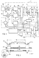
- a bus system is shown schematically as a block diagram shown according to the invention. It can be roughly divided into three areas, a donor area 1, a bus 2 and a receiver area 3. Assigned to the encoder area 1 are the facilities for the formation of video and supplementary data streams. The actual combination of these data streams into a single data stream takes place in an interface circuit 4, the output of which is the data to be transmitted for delivers the bus 2. In Fig. 1 the encoder area 1 is circumscribed with a dash-dotted line, the boundary for a monolithic integration of the encoder 1 is useful but not mandatory.
- a tuner and intermediate frequency converter 5 receives a television signal and converts it into a lower frequency range so that the converted signal fb can be digitized by means of an analog / digital converter 6.
- the associated digitization clock t1 comes from a clock source 7, which can also supply further clock signals t2, t3.
- another device can also supply the television signal mixture fb, for example a cable tuner, a video recorder, a video camera or a computer with multimedia properties, provided that these devices provide the television signal in the usual form as a television picture blanker.
- a video recorder output signal e.g. a S-VHS "signal.
- the digitized television signal mixture fd at the output of the analog / digital converter 6 is supplied in the transmitter 1 simple signal preprocessing stages, which adapted to the respective standard of the video or supplementary signal and for example are known from digital television receivers.
- the video signal preprocessing takes place in stage 8, which is referred to below as the video data source and contains those stages with which the digitized signal mixture fd Brightness and color information can be separated or decoded.
- Another Signal processing device 9, hereinafter referred to as synchronous signal detector is formed from the digitized signal mixture fd the horizontal and Vertical synchronizing signals h and v, which are also used for the correct function the video data source 8 are required.
- Another data processing stage 10 is also digitized Signal mixture fd fed.
- the supplementary data source 10 for example, teletext data or such data in the television signal mixture fd acquired are already contained as data in the analog television signal mixture fb. Because their data rate can be significantly lower than that of digitized video signals Processing is done at a low clock rate. It may therefore be useful if the tuner and intermediate frequency converter 5 has its own frequency conversion for this data performs so that the digitization with a low clock rate can be done, namely by the clock t2 in connection with its own analog / digital converter 6.2.
- sources 8 and 10 shown in FIG. 1 there may also be others.
- Certain video recorder systems are for example, the brightness and color information stored separately, so that separate processing in separate video data sources also offers itself. Similar Considerations can also be made for multiple training of the supplementary data source 10 can be employed. It may also be more sensible, specialized, but there to connect simple supplementary data sources in parallel than to provide only one is universal but also very extensive.
- the output signals d8, d10 of the individual sources are in the interface circuit 4 8, 10 brought together by means of a multiplexer 11 to form a single data stream d11. Since the data from sources 8, 10 is at least in your respective data stream d11 for the duration of a line can only come from one source, using an interpolator 12 the data d8, d10 to that of the receiver side 3 and thus the playback device predetermined number of samples can be adjusted. Appropriately It is here if the interpolation is based on the processing rate of the receiver 3 aligns, which corresponds to the third clock t3 in Fig. 3.
- the reception area 3 is one Add television receivers
- the clock t3 usually corresponds to the entire System clock and is therefore also identical to the digitization clock t1.
- a system clock is often a clock of 20.25 Mhz in digital television receivers and in Pcs a clock of 13.5 MHz is used.
- the sampling rate would be 66.6 Percent of the digitization rate of the FBAS signal fb are reduced.
- the transfer rate the data on bus 2 is your 13.5 MHz system clock PCs.
- the output signal d12 of the interpolator 12 can be generated by means of a multiplier 13 to be changed. If the output signals d8, d10 are normalized, then as a rule the multiplier 13 is not required. Of course, the individual Sources 8, 10 can also be assigned their own multipliers. In the simplest case it is a simple digit shift of the binary digits.
- the output signals d11, d12 and d13 can be recoded by means of an encoder 14 to increase the redundancy of the data to be transmitted d2 or certain Avoid data configurations (cf. the comments on FIG. 4). Redundancy can be increased, for example, by adding a parity bit will..
- identification data dk are added at the beginning and insert the end of each data block to be transmitted into the data stream d14.
- the identification data dk one is created for the block db to be transmitted Start and an end or length identifier specified.
- a content identifier ik which contains information about the Content of the respective data block enables.
- This content identifier ik is on the Receiver side 3 again a source-related separation and processing of the individual Data blocks possible.
- the identification data dk can be made up of data words or assemble data strings.
- a buffer memory 17 or FIFO Differences between the clock phases and / or data rates of the bus 2 and Compensate receiver 3 The synchronization of encoder 2 and receiver 3
- the buffer memory 16, 17 can also be used in that the buffer memory 16 with a clock signal t3 'from a clock source 7', which couples to the receiver 3 is controlled.
- a control device 18 is schematic in the block diagram of FIG. 1 shown whose function, for example, by a microprocessor on the encoder or Receiver side 1 or 3 can be implemented in a simple manner.
- the control device 18 can, for example, keep the multiplexer 11 in stationary operation will.
- the control device 18 optionally also provides a multiplication factor m to the multiplier 13.
- the control device 18 the insertion of the identification data dk via the insertion circuit 15 entirely or partially suppressed. Suppression of all or individual identifier data dk and the stopping of the multiplexer 11 correspond to different operating states, which also have an impact on recipient 3.
- the interface circuit 4 and, if appropriate, becomes the case by means of the control device 18 the source 8 or 10 switched to continuity.
- the control lines required for this are not shown in Fig. 1 for clarity.
- the identification data dk are stored in the insertion circuit 15, and the corresponding data of the respective standard can be called up by the control device 18. Using special programming means, which are not shown in Fig. 1, the Program identification data dk in the insertion circuit 15.
- the receiver 3 has a detection device 19 after the buffer memory 17 on, which is coupled to a frame memory 20. Depending on the transmitted identification data dk or a line and field counting along if necessary additionally transmitted vertical and horizontal control signals v and h, respectively the data d2 received via the bus 2 into the associated areas of the memory 20 read. There they can be used by the playback device as video or supplementary data can be read out again at any time. On the screen becomes a simultaneous rendering of image and text, also very different Sources enabled.
- the receiver 3 differs in the simplest Case not from known receivers in simple television signal bus systems.
- the first line shows schematically the analog CVBS signal fb, which also corresponds to the digitized signal fd at the output of the analog / digital converter 6.
- the line period TH contains the line return interval tz and the image interval tb.
- supplementary data for example signals or data for, can be present in the FBAS signal for a few lines in the interval tb, as already mentioned several times PAL Plus “, VPS “, CAPTION “, WST “, WSS “, ANTIOPE “, TELETEXT “, NABTS”, VITC “and others.
- the data stream d2 transmitted on bus 2 is shown schematically in the second line shown. No data transmission takes place during the line return intervals tz on the bus 2 instead or the data sent in each case are meaningless view on the recipient side 3 because they do not have valid identification data have kd.
- the data stream d2 contains distinguishable data blocks db, the beginning and end of which are determined by identification data dk that correspond to the respective Data block db are added, cf. the third line of Fig. 2.
- the identification data dk at the beginning of the block consist of a start and Content identifier sk or ik together.
- the identification data dk comprise Case two data words, but it can also be an entire data sequence.
- the content identifier ik can provide information about the respective data block length included if data blocks of different lengths are to be transmitted on bus 2 are. To identify the end of the block, however, the identification data dk most simply repeated or a separate end identifier inserted.
- the start identifier not contain a data word or a data sequence that can occur in the subsequent data block.
- the extreme values of the existing one for the start and end identifier Data range would be used, for example, would be for positive binary numbers offer binary values 0000 ... or 1111 ...
- the omission of these extreme digitization areas for the data to be transmitted on the bus is not essential Restriction. It looks different when to transmit supplementary data are, which can in principle contain any of the possible data words.
- each data word comprising 8 binary digits.
- a data word with 8 binary digits is usually also referred to as a byte.
- a first data block db1 begins with a start identifier sk consisting of all ones, the hexadecimal code FF ".
- the content identifier ik1 is in the hexadecimal code 08 ". Both identifiers together form a first block identifier, namely the identifier data dk1.
- the first data block db1 which contains, for example, supplementary data, is announced on the data bus.
- the end of the data block db1 is signaled by repeating the identifier data dk1, that is to say the same Data sequence FF, 08 "as at the beginning of the block.
- the following data dbz, which may occur in the line return interval, are not taken into account on the receiver side 3. Only when the start identifier sk reappears does the recognition device 19 activate the source-related storage of the received data d2 in the memory 20th
- the byte following the start identifier sk has the hexadecimal code 22 "and defines the content of a second data block db2.
- the identification data dk2 of the second block db2 can thus be read in hexadecimal code FF, 22 ". In this way, data transfer on the bus proceeds from block to block.
- the aforementioned collision of identification data dk with the data content of the blocks to be transmitted can be avoided by recoding the supplementary data d10 by means of the coding device 14.
- the invention takes advantage of the low data rate of the supplementary data d10 by splitting the respective data word into two or more areas and transmitting the separate areas in successive data words which are supplemented in such a way that the prohibited binary states do not occur. This is shown schematically in FIG. 4 by means of a byte sequence in the hexadecimal code. Each byte is split into two equally large digits and forms a byte pair dp that is transmitted as a new data sequence. In the left part of the figure, the relationship between the old and new positions of the two byte areas and their respective addition j is shown.
- the resulting data sequence is shown on the right.
- the forbidden "data sequence FF” is therefore no longer present in the block content of the new data stream and is therefore available exclusively for the identification data dk.
- the increase in the data rate to twice the value plays no role in the low data rate of the supplementary data.
Abstract
Description
Die Erfindung betrifft ein Bussystem mit einem hierfür angepaßten Geber und Empfänger für eine digitale Fernsehsignal-Verarbeitungseinrichtung, die auch als Multimedia-Verarbeitungseinrichtung ausgebildet sein kann. Das Bussysteme dient dazu, Videodaten mindestens einer Videodatenquelle und/oder Ergänzungsdaten einer oder mehrerer Ergänzungsdatenquellen zwischen dem Geber und dem Empfänger mittels Datenleitungen, also eines sogenannten Busses, zu übertragen.The invention relates to a bus system with a transmitter and receiver adapted for this for a digital television signal processing device, also called a multimedia processing device can be trained. The bus system serves Video data from at least one video data source and / or supplementary data from one or several supplementary data sources between the donor and the recipient by means of data lines, i.e. a so-called bus.
Der Bus verbindet räumlich getrennte Signalverarbeitungseinrichtungen, z.B. Prozessoren, die in einem oder in mehreren Geräten zusammenwirken. Im einfachsten Fall verbindet der Bus Signalverarbeitungseinrichtungen auf einer Schaltungsplatine. Eine besondere Erschwernis kann hierbei sein, daß die Takte der Signalverarbeitungseinrichtungen nicht zusammenpassen.The bus connects spatially separate signal processing devices, e.g. Processors, that work together in one or more devices. In the simplest case the bus connects signal processing devices on a circuit board. A A particular difficulty can be that the clocks of the signal processing devices do not match.
Anwendungsbeispiele für derartige Bussysteme können Fernsehempfänger sein, die je nach Bedarf normgerechte oder nichtnormgerechte Fernsehsignale verarbeiten sollen, wobei neben den Fernsehsignalen auch Ergänzungsdaten, wie z.B. Stereo- oder Mehrfachton, Bildschirm-Textinformation oder Informationen fernsehsignalbezogener Datendienste, ebenfalls verarbeitet werden sollen. Bisher übernehmen in der Regel spezialisierte Prozessoren die einzelnen Funktionen und leiten die jeweiligen Daten über eigene Busse an die Ausgabeeinrichtungen oder andere Prozessoren weiter.Application examples for such bus systems can be television receivers, each should process standard or non-standard television signals as required, in addition to the television signals also supplementary data such as Stereo or multiple sound, On-screen text information or information from television signal-related data services, should also be processed. So far, usually specialized Processors the individual functions and transfer the respective data own buses to the output devices or other processors.
In modernen Fernsehempfängern und in multimediatüchtigen PCs (=Personal Computer) stehen immer leistungsfähigere Prozessoren für die Signalverarbeitung zur Verfügung, so daß es nahezu ohne zusätzlichen Schaltungsaufwand allein durch eine geeignete Programmierung der Prozessoren möglich ist, eine Vielzahl von Fernsehstandards mit Text-, Ton- und weiteren Informationen zu verarbeiten und auf den vorhandenen Ausgabeeinrichtungen wiederzugeben. Der Multimediabereich mit einem hochauflösenden Fernseh- oder Computerbildschirm und einem leistungsfähigen Tonwiedergabesystem bietet hierbei besonders viele Darstellungs- und Wiedergabemöglichkeiten. Die hohe Datenrate der Videodatenquellen und die Vielzahl der möglichen Ergänzungsdaten stellen dabei hohe Forderungen an die jeweiligen Bussysteme, die in der Regel als Parallelbussysteme ausgeführt sind. Für die unterschiedlichen Datenströme werden je nach Taktrate und Datenbreite getrennte Busse verwendet. Hier ergeben sich bei Mehrnormen-Fernsehempfängern und insbesondere bei Multimediasystemen Engpässe, denn bei einem Parallelbus ist für jede Stelle der zu übertragenden Daten auf der Geber- und Empfängerseite, die in der Regel durch monolithisch integrierte Prozessoren gebildet sind, jeweils ein Gehäuseanschluß erforderlich. Die Anzahl der für Busverbindungen zur Verfügung stehenden Anschlüsse ist aber aus Kosten-, Flächen- und Verdrahtungsgründen begrenzt und stellt ein wesentliches Hindernis für den immer komplexer werdenden Datenaustausch zwischen den einzelnen Prozessoren dar.In modern television receivers and in multimedia-capable PCs (= personal computers) more and more powerful processors are available for signal processing, so that it is almost without additional circuitry alone by a Appropriate programming of the processors is possible, a variety of television standards with text, sound and other information to process and on the reproduce existing output devices. The multimedia area with one high definition television or computer screen and a powerful one Sound playback system offers a particularly large number of display and playback options. The high data rate of the video data sources and the multitude of Possible additional data places high demands on the respective bus systems, which are usually designed as parallel bus systems. For the different Data streams are used depending on the clock rate and data width separate buses. This results in multi-standard television receivers and in particular in Multimedia systems bottlenecks, because with a parallel bus there is too much for every point transmitting data on the donor and receiver side, which is usually monolithic integrated processors are formed, one housing connection required. The number of connections available for bus connections is but limited for cost, space and wiring reasons and represents an essential one Obstacle to the increasingly complex data exchange between the individual processors.
Aufgabe der Erfindung ist es daher, für eine digitale Fernsehsignal-Verarbeitungseinrichtung, die auch durch eine Multimedia-Verarbeitungseinrichtung realisiert sein kann, ein flexibles Bussystem für Video- und Ergänzungsdaten anzugeben, das an unterschiedliche Fernsehstandards und an unterschiedliche Verarbeitungseinrichtungen angepaßt werden kann. Dabei ist insbesondere der Geber des Bussystems so zu optimieren, daß er sowohl mit vorhandenen, meist einfachen Empfängern zusammenarbeiten kann als auch mit sehr flexiblen Empfängern, deren leistungsfähige Prozessoren ohne eine Schaltungsänderung lediglich über eine einmalige Programmierung an das Bussystem anpaßbar sind.The object of the invention is therefore, for a digital television signal processing device, which can also be implemented by a multimedia processing device can specify a flexible bus system for video and supplementary data that different television standards and different processing facilities can be adjusted. The encoder of the bus system is particularly closed optimize that he can work with existing, mostly simple receivers can as well with very flexible receivers, their powerful processors without changing the circuit, only via one-time programming the bus system is adaptable.
Die Aufgabe wird entsprechend der Erfindung durch die Merkmale des Anspruchs 1 wie folgt gelöst:
- ein Bussystem für eine Fernsehsignal-Verarbeitungseinrichtung zur Übertragung von Videodaten mindestens einer Videodatenquelle und/oder Ergänzungsdaten einer oder mehrerer Ergänzungsdatenquellen zwischen einem Geber und einem Empfänger mittels eines Busses, wobei
- die Videodaten ursprünglich mit einem ersten Takt und die Ergänzungsdaten ursprünglich mit dem gleichen oder einem zweiten Takt oder mit einem weiteren Takt verknüpft sind,
- auf der Geberseite mittels einer Interfaceschaltung aus den Video- und/oder Ergänzungsdaten ein einziger Datenstrom für den Bus gebildet ist, indem die Interfaceschaltung die Video- und/oder Ergänzungsdaten quellenweise jeweils in zeitlich aufeinanderfolgende Blöcke mit Kennungsdaten für eine Start-, End- oder Längen- und Inhaltskennung zusammenfaßt,
- die Datenrate der übertragenen Blöcke durch einen dritten Takt definiert ist, dessen Taktrate mit der des ersten, zweiten oder eines der weiteren Takte oder der Datenverarbeitungsrate der Empfängerseite des Bussystems verkoppelt ist, und
- auf der Empfängerseite mittels einer Erkennungseinrichtung aus dein empfangenen Datenstrom über die Kennungsdaten die einzelnen Blöcke für die weitere Verarbeitung wieder trennbar sind.
- a bus system for a television signal processing device for transmitting video data of at least one video data source and / or supplementary data of one or more supplementary data sources between a transmitter and a receiver by means of a bus, wherein
- the video data are originally linked to a first clock and the supplementary data are initially linked to the same or a second clock or to a further clock,
- a single data stream for the bus is formed on the encoder side by means of an interface circuit from the video and / or supplementary data, in that the interface circuit sources the video and / or supplementary data in each case in chronologically successive blocks with identification data for a start, end or length - and summarizes content identifier,
- the data rate of the transmitted blocks is defined by a third clock, the clock rate of which is coupled to that of the first, second or one of the further clocks or the data processing rate of the receiver side of the bus system, and
- on the receiver side by means of a recognition device from the received data stream via the identification data, the individual blocks can be separated again for further processing.
Die Vorteile der Erfindung bestehen neben der Einsparung von Anschlußkontakten
auf der Geber- und Empfängerseite sowie einer entsprechenden Einsparung von Busleitungen
im Wesentlichen in einer Erhöhung der Flexibilität für den jeweiligen Anwendungsfall.
Ferner ist auf der Geberseite nur eine eine einzige Interfaceschaltung
für die Video- und Ergänzungsdatenquellen erforderlich. Die Kennzeichnung der
übertragenen Datenblöcke durch die Kennungsdaten für Start-, End- oder Längen- und
Inhaltskennung ermöglicht dabei auf der Empfängerseite auf einfache Weise eine
Trennung. Auf der Empfängerseite kann die Auswertung der horizontalen und vertikalen
Synchronsignale zur Bestimmung der jeweiligen Fernsehsignal-Zeilennummer
entfallen. In der Regel reichen für die Trennung die programmierbaren Erkennungseinrichtungen
in den empfängerseitigen Prozessoren aus. Konflikte bei der Datenzuordnung
werden durch die Kennungsdaten auf der Empfängerseite sicher vermieden,
auch wenn die Datenblöcke gegebenenfalls in ![]()
![]()
Im Fernsehsignal sind die quellenbezogenen Signale unterschiedlichen Zeilen zugeordnet, somit werden die einzelnen Datenblöcke auch zu unterschiedlichen Zeitintervallen gebildet, so daß sie auch zeitlich getrennt auf dem Bus übertragen werden können. Die Textdaten, z.B. beim weit verbreiteten Videotext-Fernsehstandard, werden bekanntlich nur innerhalb bestimmter Zeilen der vertikalen Austastlücke in das Fernsehsignalgemisch eingefügt - eine Videoinformation ist in diesen Zeilen nicht vorhanden. Durch die flexible Steuerung der Kennungsdaten ist es aber auch möglich, während beliebiger Zeilen oder statt ganzer Bildwiedergabeseiten Text- oder andere Daten über den Bus zu übertragen. Über die jeweilige Kennung ist auf der Empfängerseite auch in diesen Fällen ein sichere Trennung ohne Kenntnis der jeweiligen Zeilennummer möglich.In the television signal, the source-related signals are assigned to different lines, thus the individual data blocks are also at different time intervals formed so that they can also be transmitted separately on the bus. The text data, e.g. in the widespread teletext television standard as is known, only within certain lines of the vertical blanking interval in the television signal mixture inserted - there is no video information in these lines. Thanks to the flexible control of the identification data, it is also possible text or other text during any lines or instead of full image display pages Transfer data over the bus. The respective identifier is on the receiving end In these cases, too, a safe separation without knowing the respective line number possible.
Von Vorteil ist es ferner, wenn bereits auf der Geberseite eine Vorverarbeitung der zugeführten Video- oder Ergänzungsdaten erfolgt, um die zu übertragende Datenmenge zu reduzieren und damit auch den Prozessor auf der Empfängerseite zu entlasten. Dies ist besonders bei der Verarbeitung von Text- oder Audiodaten sinnvoll, weil ihre Datenrate wesentlich nieder ist als bei Videodaten und eine Überabtastung durch den vorgegebenen Videosignal-Digitalisierungstakt lediglich die Datenmenge sinnlos erhöht. Spezialisierte Verarbeitungsschaltungen, die nur eine relativ kleine Fläche der monolithisch integrierten Geberschaltung erfordern, liefern gemäß der Erfindung diese Daten mit einer angepaßten und damit möglichst niederen Datenrate. Über den Bus werden diese Daten zwar mit einer hohen Datenrate übertragen, aber dafür ist die Übertragung nach kurzer Zeit, nämlich nach dem Eintreffen der Endkennung, abgeschlossen. Bis zum Eintreffen der nächsten Startkennung kann der Empfänger den Bus unberücksichtigt lassen.It is also advantageous if preprocessing of the supplied video or supplementary data takes place to the amount of data to be transmitted to reduce and thus relieve the processor on the receiver side. This is particularly useful when processing text or audio data because their data rate is much lower than that of video data and oversampling by the specified video signal digitization clock, the amount of data is useless elevated. Specialized processing circuits that take up only a relatively small area of the require monolithically integrated transmitter circuit, deliver this according to the invention Data with an adapted and therefore the lowest possible data rate. Via the bus this data is transmitted at a high data rate, but this is what Transfer completed after a short time, namely after the arrival of the final identifier. The receiver can use the bus until the next start identifier arrives ignored.
Erfolgt dagegen die Datenbildung aus dem überabgetasteten Signalgemisch erst auf der Empfängerseite, was mittels eines speziellen Bus-Betriebes nach der Erfindung ebenfalls möglich ist, dann werden das digitalisierte Fernseh-Signalgemisch, also das mit einer hohen Abtastrate digitalisierte FBAS-Signal, oder die Ausgangsdaten der einzelnen Vorverarbeitungsstufen im Geber unverändert über den Bus übertragen. Erst auf der Empfängerseite werden dann aus dem übertragenen Datenstrom die eigentlich interessanten Daten, beispielsweise mittels eines schnellen Mikroprozessors, gebildet. Schnelle Mikroprozessoren in Multimedia- oder Fernsehsignal-Verarbeitungseinrichtungen lassen sich für diesen unzweckmäßigen Busbetrieb zwar programmieren, allerdings wird dabei ein hoher Teil der Verarbeitungskapazität belegt, der dann für andere Signalverarbeitungsaufgaben nicht mehr zur Verfügung steht. Durch die Vorverarbeitung auf der Geberseite gemäß der Erfindung kann jedoch eine wesentliche Entlastung der Prozessoren auf der Empfängerseite erreicht werden.On the other hand, the data is only generated from the oversampled signal mixture the receiver side, which by means of a special bus operation according to the invention is also possible, then the digitized television signal mix, that is digitized composite signal with a high sampling rate, or the output data of the individual preprocessing stages in the encoder are transmitted unchanged via the bus. It is only on the receiver side that the transmitted data stream actually becomes interesting data, for example using a fast microprocessor, educated. Fast microprocessors in multimedia or television signal processing equipment can be used for this inappropriate bus operation programming, however a large part of the processing capacity is used, which is then no longer available for other signal processing tasks stands. However, by preprocessing on the encoder side according to the invention the processors on the receiver side are relieved will.
Die Erfindung und vorteilhafte Ausgestaltungen werden nun anhand der Figuren der
Zeichnung näher erläutert:
In Fig. 1 ist schematisch als Blockschaltbild ein Ausführungsbeispiel eines Bussystems
nach der Erfindung dargestellt. Es läßt sich grob in drei Bereiche gliedern, einen Geberbereich
1, einen Bus 2 und einen Empfängerbereich 3. Dem Geberbereich 1 zugeordnet
sind die Einrichtungen zur Bildung der Video- und Ergänzungsdatenströme.
Die eigentliche Zusammenfassung dieser Datenströme zu einem einzigen Datenstrom
erfolgt in einer Interfaceschaltung 4, deren Ausgang die zu übertragenden Daten für
den Bus 2 liefert. In Fig. 1 ist der Geberbereich 1 mit einer strichpunktierten Linie umschrieben,
wobei die Grenzziehung für eine monolithische Integration des Gebers 1
zweckmäßig aber nicht zwingend ist.In Fig. 1, an embodiment of a bus system is shown schematically as a block diagram
shown according to the invention. It can be roughly divided into three areas, a
Für das Ausführungsbeispiel von Fig. 1 ist angenommen, daß ein Tuner-und-Zwischenfrequenzumsetzer
5 ein Fernsehsignal empfängt und es in einen tieferen
Frequenzbereich umsetzt, damit das umgesetzte Signal fb mittels eines Analog/Digital-Umsetzers
6 digitalisiert werden kann. Der zugehörige Digitalisierungstakt
t1 stammt aus einer Taktquelle 7, die auch weitere Taktsignale t2, t3 liefern kann.
Statt des Tuner-und-Zwischenfrequenzumsetzer 5 kann selbstverständlich auch eine
andere Einrichtung das Fernsehsignalgemisch fb liefern, beispielsweise ein Kabeltuner,
ein Videorekorder, eine Videokamera oder ein Rechner mit Multimediaeigenschaften,
sofern diese Einrichtungen das Fernsehsignal in der üblichen Form als Fernseh-Bild-Austast-Synchron-Signalgemisch
(= FBAS-Signal) oder als Videorecorder-Ausgangssignal,
z.B. ein
Das digitalisierte Fernsehsignalgemisch fd am Ausgang des Analog/Digital-Umsetzers
6 ist im Geber 1 einfachen Signalvorverarbeitungsstufen zugeführt, die an
den jeweiligen Standard des Video- oder Ergänzungssignals angepaßt und beispielsweise
aus digitalen Fernsehempfängern bekannt sind. Die Videosignalvorverarbeitung
erfolgt dabei in der Stufe 8, die im folgenden als Videodatenquelle bezeichnet wird
und diejenigen Stufen enthält, mit denen aus dem digitalisierten Signalgemisch fd die
Helligkeits- und Farbinformation getrennt oder dekodiert werden kann. Eine weitere
Signalverarbeitungseinrichtung 9, die im folgenden als Synchronsignaldetektor bezeichnet
wird, bildet aus dem digitalisierten Signalgemisch fd die Horizontal- und
Vertikal-Synchronsignale h bzw. v, die beispielsweise auch für die richtige Funktion
der Videodatenquelle 8 erforderlich sind. Eine weitere Datenverarbeitungsstufe 10, die
im folgenden als Ergänzungsdatenquelle bezeichnet wird, wird ebenfalls mit dem digitalisierten
Signalgemisch fd gespeist. Mit der Ergänzungsdatenquelle 10 werden
beispielsweise Teletextdaten oder solche Daten im Fernsehsignalgemisch fd erfaßt, die
bereits im analogen Fernsehsignalgemisch fb als Daten enthalten sind. Da ihre Datenrate
wesentlich niedriger als die der digitalisierten Videosignale ist, kann auch ihre
Verarbeitung mit einer niedrigen Taktrate erfolgen. Es kann daher zweckmäßig sein,
wenn der Tuner und Zwischenfrequenzumsetzer 5 für diese Daten eine eigene Frequenzumsetzung
durchführt, so daß die Digitalisierung mit einer niedrigen Taktrate
erfolgen kann, nämlich durch den Takt t2 in Verbindung mit einem eigenen Analog/Digital-Umsetzer
6.2.The digitized television signal mixture fd at the output of the analog /
Es wird darauf hingewiesen, daß außer den in Fig. 1 dargestellten Quellen 8 und 10
auch weitere vorhanden sein können. Bei bestimmten Videorecordersystemen sind
beispielsweise die Helligkeits- und Farbinformationen getrennt gespeichert, so daß
sich auch eine getrennte Verarbeitung in getrennten Videodatenquellen anbietet. Ähnliche
Überlegungen können auch für eine Mehrfachausbildung der Ergänzungsdatenquelle
10 angestellt werden. Eventuell ist es auch dort sinnvoller, spezialisierte, aber
einfache Ergänzungsdatenquellen parallel zu schalten, als eine einzige vorzusehen, die
zwar universell aber auch sehr umfangreich ist.It should be noted that in addition to
In der Interfaceschaltung 4 werden die Ausgangssignale d8, d10 der einzelnen Quellen
8, 10 mittels eines Multiplexers 11 zu einem einzigen Datenstrom d11 zusammengeführt.
Da in dein jeweiligen Datenstrom d11 die Daten der Quellen 8, 10 mindestens
für die Dauer einer Zeile nur von einer Quelle stammen, können mittels eines Interpolators
12 die Daten d8, d10 an die von der Empfängerseite 3 und damit der Wiedergabeeinrichtung
vorgegebenen Anzahl von Abtastwerten angepaßt werden. Zweckmäßig
ist es hierbei, wenn sich die Interpolation nach der Verarbeitungsrate des Empfängers
3 richtet, die in Fig. 3 dem dritten Takt t3 entspricht. Dies ist besonders dann erforderlich,
wenn der Empfängerbereich 3 einen fest vorgegebenen Verarbeitungstakt
aufweist, beispielsweise wenn ein persönlicher Rechner (=PC) als Multimedia-Wiedergabeeinrichtung
vorgesehen ist. Ist dagegen der Empfangsbereich 3 einem
Fernsehempfänger zuzurechnen, dann entspricht in der Regel der Takt t3 dem gesamten
Systemtakt und ist somit auch identisch zum Digitalisierungstakt t1. Als Systemtakt
wird in digitalen Fernsehempfängern häufig ein Takt von 20,25 Mhz und in Pcs
ein Takt von 13,5 Mhz verwendet. Mit dein Interpolator 12 in der Interfaceschaltung 4
würde im Falle der Bild- oder Textwiedergabe über einen PC die Abtastrate auf 66,6
Prozent der Digitalisierungsrate des FBAS-Signals fb reduziert werden. Die Übertragungsrate
der Daten auf dem Bus 2 ist entspricht dabei dein 13,5MHz-Systemtakt des
PCs.The output signals d8, d10 of the individual sources are in the interface circuit 4
8, 10 brought together by means of a
Das Ausgangssignal d12 des Interpolators 12 kann mittels eines Multiplizierers 13
verändert werden. Sind die Ausgangssignale d8, d10 normiert, dann ist in der Regel
der Multiplizierer 13 nicht erforderlich. Selbstverständlich können den einzelnen
Quellen 8,10 auch eigene Multiplizierer zugeordnet sein. Im einfachsten Fall handelt
es sich um eine einfache Stellenverschiebung der Binärstellen.The output signal d12 of the
Die Ausgangssignale d11, d12 bzw. d13 können mittels eines Codierers 14 umkodiert
werden, um die Redundanz der zu übertragenden Daten d2 zu erhöhen oder bestimmte
Datenkonfigurationen (vrgl. hierzu die Ausführungen zu Fig. 4) zu vermeiden.
Die Redundanz kann beispielsweise durch das Hinzufügen eines Parity-Bits vergrößert
werden..The output signals d11, d12 and d13 can be recoded by means of an
Mittels einer Einfügungsschaltung 15 werden Kennungsdaten dk (vrgl. Fig. 2) zu Beginn
und Ende jedes zu übertragenden Datenblockes in den Datenstrom d14 eingefügt.
Mit den Kennungsdaten dk wird für den jeweils zu übertragenden Block db eine
Start- und eine End- oder Längenkennung vorgegeben. Ferner wird mit den Kennungsdaten
auch eine Inhaltskennung ik eingefügt, die eine Information über den
Inhalt des jeweiligen Datenblocks ermöglicht. Über diese Inhaltskennung ik ist auf der
Empfängerseite 3 wieder eine quellenbezogene Trennung und Verarbeitung der einzelnen
Datenblöcke möglich. Die Kennungsdaten dk können sich dabei aus Datenworten
oder Datenfolgen zusammensetzen.By means of an
Den Ausgang der Interfaceschaltung 4 bildet ein Pufferspeicher 16 oder FIFO (= First
in first out), der gegebenenfalls vorhandene Taktunterschiede zwischen dem Datenstrom
d14 und dem Datenstrom d2 auf dem Bus 2 ausgleichen kann. In der Regel enthält
auch die Empfangsseite 3 im Eingang einen Pufferspeicher 17 oder FIFO, um
Unterschiede zwischen den Taktphasen und/oder Datenraten des Busses 2 und des
Empfängers 3 auszugleichen Die Synchronisation des Gebers 2 und des Empfängers 3
über die Pufferspeicher 16, 17 kann auch dadurch erfolgen, daß der Pufferspeicher 16
mit einem Taktsignal t3' aus einer Taktquelle 7', die mit dem Empfänger 3 verkoppelt
ist, angesteuert wird.The output of the interface circuit 4 forms a
In dem Blockschaltbild von Fig. 1 ist schließlich eine Steuereinrichtung 18 schematisch
dargestellt, deren Funktion beispielsweise durch einen Mikroprozessor auf der Geber- oder
Empfängerseite 1 bzw. 3 auf einfache Weise realisiert sein kann. Mittels der Steuereinrichtung
18 kann beispielsweise der Multiplexer 11 im stationären Betrieb gehalten
werden. Die Steuereinrichtung 18 liefert gegebenenfalls auch einen Multiplikationsfaktor
m an den Multiplizierer 13. Ferner kann mit der Steuereinrichtung 18 auch
die Einfügung der Kennungsdaten dk über die Einfügungsschaltung 15 ganz oder
teilweise unterdrückt werden. Die Unterdrückung aller oder einzelner Kennungsdaten
dk und das Anhalten des Multiplexers 11 entsprechen verschiedenen Betriebszuständen,
die auch Auswirkungen auf den Empfänger 3 haben. Für Testzwecke kann es
beispielsweise erforderlich sein, daß im Empfänger 3 das digitalisierte Signal fd oder
eines der Signale d8, d10 über eine längeren Zeitraum zur Verfügung steht. Für diesen
Fall wird mittels der Steuereinrichtung 18 die Interfaceschaltung 4 und gegebenenfalls
die Quelle 8 oder 10 auf Durchgang geschaltet. Die hierfür erforderlichen Steuerleitungen
sind in Fig. 1 der Übersicht wegen nicht dargestellt.Finally, a
In der Einfügungsschaltung 15 sind die Kennungsdaten dk gespeichert, die entsprchend
der jeweiligen Norm von der Steuereinrichtung 18 abgerufen werden können.
Über spezielle Programmiermittel, die in Fig. 1 nicht dargestellt sind, lassen sich die
Kennungsdaten dk in der Einfügungsschaltung 15 programmieren.The identification data dk are stored in the
Der Empfänger 3 weist nach dem Pufferspeicher 17 eine Erkennungseinrichtung 19
auf, die mit einem Vollbildspeicher 20 gekoppelt ist. Je nach den übertragenen Kennungsdaten
dk oder einer mitlaufenden Zeilen- und Halbbildzählung über gegebenenfalls
zusätzlich übertragene Vertikal- und Horizontalsteuersignale v bzw. h werden
die über den Bus 2 empfangenen Daten d2 in die zugehörigen Bereiche des Speichers
20 eingelesen. Dort können sie von der Wiedergabeeinrichtung als Video- oder Ergänzungsdaten
zu beliebigen Zeitpunkten wieder ausgelesen werden. Auf dem Bildschirm
wird somit eine gleichzeitige Wiedergabe von Bild und Text, auch ganz unterschiedlicher
Quellen ermöglicht. Der Empfänger 3 unterscheidet sich im einfachsten
Fall nicht von bekannten Empfängern in einfachen Fernsehsignal-Bussystemen.The
In Fig. 2 sind schematisch im Zeitdiagramm einige Signale des Bussystems von Fig. 1
dargestellt. Die erste Zeile zeigt schematisch das analoge FBAS-Signal fb, dem auch
das digitalisierte Signal fd am Ausgang des Analog/Digitalumsetzers 6 entspricht. Die
Zeilenperiode TH enthält dabei das Zeilenrücklaufintervall tz und das Bildintervall tb.
Während des Vertikalrücklaufs, während der die Bildwiedergabeeinrichtung dunkel
geschaltet ist, können wie bereits mehrfach erwähnt im FBAS-Signal während einiger
Zeilen im Intervall tb Ergänzungsdaten vorhanden sein, z.B. Signale oder Daten für
In der zweiten Zeile wird der auf dem Bus 2 übertragene Datenstrom d2 schematisch
dargestellt. Während der Zeilenrücklaufintervalle tz findet entweder keine Datenübertragung
auf dem Bus 2 statt oder die jeweils gesendeten Daten sind als bedeutunglos
auf der Empfängerseite 3 anzusehen, weil sie keine gültigen Kennungsdaten
kd aufweisen. Der Datenstrom d2 enthält auf diese Weise unterscheidbare Datenblöcke
db, deren Anfang und Ende durch Kennungsdaten dk bestimmt sind, die dem jeweiligen
Datenblock db hinzugefügt werden, vgl. die dritte Zeile von Fig. 2. Im einfachsten
Fall setzen sich die Kennungsdaten dk am Blockanfang aus einer Start- und
Inhaltskennung sk bzw. ik zusammen. Die Kennungsdaten dk umfassen im einfachsten
Fall zwei Datenworte, es kann sich jedoch auch um eine ganze Datenfolge handeln.
Die Inhaltskennung ik kann dabei eine Information über die jeweilige Datenblocklänge
enthalten, wenn unterschiedlich lange Datenblöcke auf dem Bus 2 zu übertragen
sind. Zur Kennzeichnung des Blockendes werden die Kennungsdaten dk jedoch
am einfachsten wiederholt oder eine separate Endkennung eingefügt. Bei der
Startkennung ist es wichtig, daß sie kein Datenwort oder keine Datenfolge enthält, die
im nachfolgenden Datenblock auftreten können. Bei digitalisierten Analogsignalen,
insbesondere wenn sie normiert sind, ist die Einhaltung dieser Bedingung nicht sehr
schwierig, wenn für die Start- und Endkennung die Extremwerte des vorhandenen
Datenbereiches verwendet werden, beispielsweise würden sich für positive Binärzahlen
die Binärwerte 0000... oder 1111... anbieten. Die Auslassung dieser extremen Digitalisierungsbereiche
für die auf dem Bus zu übertragenden Daten stellt keine wesentliche
Einschränkung dar. Anders sieht es aus, wenn Ergänzungsdaten zu übertragen
sind, die prinzipiell jedes der möglichen Datenworte enthalten können.The data stream d2 transmitted on
In Fig. 3 ist der übertragene Datenstrom d2 auf dem Bus 2 schematisch anhand eines
Zahlenbeispiels dargestellt, wobei jedes Datenwort 8 Binärstellen umfaßt. Ein Datenwort
mit 8 Binärstellen wird üblicherweise auch als Byte bezeichnet. Ein erster Datenblock
db1 beginnt mit einer Startkennung sk aus lauter Einsen, die dem Hexadezimalcode
Das nach der Startkennung sk folgende Byte hat den Hexadezimalcode
Die bereits erwähnte Kollision von Kennungsdaten dk mit dem Dateninhalt der zu
übertragenden Blöcke kann durch eine Umcodierung der Ergänzungsdaten d10 mittels
der Codiereinrichtung 14 vermieden werden. Hierbei macht sich die Erfindung die
geringe Datenrate der Ergänzungsdaten d10 zunutze, indem das jeweilige Datenwort
in zwei oder mehr Bereiche aufgespalten wird und die getrennten Bereiche in aufeinanderfolgenden
Datenworten übertragen werden, die so ergänzt sind, daß die verbotenen
Binärzustände nicht auftreten. In Fig. 4 ist dies mittels einer Bytefolge im Hexadezimalcode
schematisch dargestellt. Jedes Byte wird dabei in zwei gleichgroße Stellenbereiche
aufgespalten und bilden ein Byte-Paar dp, das als neue Datenfolge übertragen
wird. Im linken Teil der Figur wird der Zusammenhang zwischen alter und
neuer Position der beiden Byte-Bereiche und ihre jeweilige Ergänzung j dargestellt.
Auf der rechten Seite ist die resultierende Datenfolge dargestellt. Die
Claims (12)
Priority Applications (5)
| Application Number | Priority Date | Filing Date | Title |
|---|---|---|---|
| EP96118424A EP0843467B1 (en) | 1996-11-16 | 1996-11-16 | Bussystem for a television signal processing device |
| DE59611195T DE59611195D1 (en) | 1996-11-16 | 1996-11-16 | Bus system for a television signal processing device |
| JP9313827A JPH10271462A (en) | 1996-11-16 | 1997-11-14 | Bus system for television signal processor |
| KR1019970059952A KR100589016B1 (en) | 1996-11-16 | 1997-11-14 | Bus system for a television signal processing device |
| US08/970,945 US6137538A (en) | 1996-11-16 | 1997-11-14 | Bus system for a television signal processing device |
Applications Claiming Priority (1)
| Application Number | Priority Date | Filing Date | Title |
|---|---|---|---|
| EP96118424A EP0843467B1 (en) | 1996-11-16 | 1996-11-16 | Bussystem for a television signal processing device |
Publications (2)
| Publication Number | Publication Date |
|---|---|
| EP0843467A1 true EP0843467A1 (en) | 1998-05-20 |
| EP0843467B1 EP0843467B1 (en) | 2005-02-09 |
Family
ID=8223406
Family Applications (1)
| Application Number | Title | Priority Date | Filing Date |
|---|---|---|---|
| EP96118424A Expired - Lifetime EP0843467B1 (en) | 1996-11-16 | 1996-11-16 | Bussystem for a television signal processing device |
Country Status (5)
| Country | Link |
|---|---|
| US (1) | US6137538A (en) |
| EP (1) | EP0843467B1 (en) |
| JP (1) | JPH10271462A (en) |
| KR (1) | KR100589016B1 (en) |
| DE (1) | DE59611195D1 (en) |
Cited By (1)
| Publication number | Priority date | Publication date | Assignee | Title |
|---|---|---|---|---|
| DE102005056709A1 (en) * | 2005-11-28 | 2007-06-06 | Siemens Ag | Method and device for coupling at least two independent bus systems |
Families Citing this family (3)
| Publication number | Priority date | Publication date | Assignee | Title |
|---|---|---|---|---|
| US6844895B1 (en) | 1999-11-15 | 2005-01-18 | Logitech Europe S.A. | Wireless intelligent host imaging, audio and data receiver |
| KR100779595B1 (en) * | 2001-11-17 | 2007-11-26 | 주식회사 포스코 | Apparatus for removal of attaching scale on roller table |
| US20090086096A1 (en) * | 2006-01-05 | 2009-04-02 | Amit Kumar Singh | Raw Mode for Vertical Blanking Interval (VBI) Data |
Citations (7)
| Publication number | Priority date | Publication date | Assignee | Title |
|---|---|---|---|---|
| WO1992000582A1 (en) * | 1990-06-27 | 1992-01-09 | Wardco | Digital color tv for personal computers |
| US5359367A (en) * | 1989-10-09 | 1994-10-25 | Videologic Limited | Personal computer with broadcast receiver on expansion board controlled by computer microprocessor |
| WO1994024670A1 (en) * | 1993-04-16 | 1994-10-27 | Data Translation, Inc. | Synchronizing digital audio to digital video |
| EP0633692A2 (en) * | 1993-07-08 | 1995-01-11 | Matsushita Electric Industrial Co., Ltd. | Data transmission apparatus for transmitting digital video and audio data between respective audio visual apparatuses, and method therefor |
| EP0690630A2 (en) * | 1994-06-27 | 1996-01-03 | Sony Corporation | Digital serial data interface suitable for video and audio data |
| EP0703713A2 (en) * | 1994-09-22 | 1996-03-27 | Sony Corporation | Packet receiving device |
| EP0726680A2 (en) * | 1995-02-09 | 1996-08-14 | Mitsubishi Denki Kabushiki Kaisha | Multimedia information processing system |
Family Cites Families (13)
| Publication number | Priority date | Publication date | Assignee | Title |
|---|---|---|---|---|
| GB8929152D0 (en) * | 1989-12-22 | 1990-02-28 | Gen Electric | A digital augmentation system for actv-ii |
| US5455629A (en) * | 1991-02-27 | 1995-10-03 | Rca Thomson Licensing Corporation | Apparatus for concealing errors in a digital video processing system |
| US5168356A (en) * | 1991-02-27 | 1992-12-01 | General Electric Company | Apparatus for segmenting encoded video signal for transmission |
| US5166781A (en) * | 1991-05-10 | 1992-11-24 | Thomson Consumer Electronics, Inc. | Apparatus for identifying standard and non-standard video signals |
| JPH06121244A (en) * | 1992-10-07 | 1994-04-28 | Sanyo Electric Co Ltd | Television receiver |
| US5784110A (en) * | 1993-11-30 | 1998-07-21 | General Electric Company | Data processor for assembling transport data packets |
| JPH08251552A (en) * | 1995-03-08 | 1996-09-27 | Toshiba Corp | Teletext receiver |
| WO1997000564A2 (en) * | 1995-06-15 | 1997-01-03 | Hall, David | Communication system for superimposing data onto a video signal |
| JPH0993550A (en) * | 1995-09-22 | 1997-04-04 | Toshiba Corp | Supplement program detection and display device |
| JPH0998390A (en) * | 1995-10-03 | 1997-04-08 | Matsushita Electric Ind Co Ltd | Television receiver for teletext broadcasting |
| JPH09214904A (en) * | 1996-02-05 | 1997-08-15 | Matsushita Electric Ind Co Ltd | Television receiver and additional information transmitting method |
| US5883670A (en) * | 1996-08-02 | 1999-03-16 | Avid Technology, Inc. | Motion video processing circuit for capture playback and manipulation of digital motion video information on a computer |
| JPH10322668A (en) * | 1997-05-14 | 1998-12-04 | Toshiba Corp | Television receiver |
-
1996
- 1996-11-16 EP EP96118424A patent/EP0843467B1/en not_active Expired - Lifetime
- 1996-11-16 DE DE59611195T patent/DE59611195D1/en not_active Expired - Lifetime
-
1997
- 1997-11-14 JP JP9313827A patent/JPH10271462A/en active Pending
- 1997-11-14 US US08/970,945 patent/US6137538A/en not_active Expired - Fee Related
- 1997-11-14 KR KR1019970059952A patent/KR100589016B1/en not_active IP Right Cessation
Patent Citations (7)
| Publication number | Priority date | Publication date | Assignee | Title |
|---|---|---|---|---|
| US5359367A (en) * | 1989-10-09 | 1994-10-25 | Videologic Limited | Personal computer with broadcast receiver on expansion board controlled by computer microprocessor |
| WO1992000582A1 (en) * | 1990-06-27 | 1992-01-09 | Wardco | Digital color tv for personal computers |
| WO1994024670A1 (en) * | 1993-04-16 | 1994-10-27 | Data Translation, Inc. | Synchronizing digital audio to digital video |
| EP0633692A2 (en) * | 1993-07-08 | 1995-01-11 | Matsushita Electric Industrial Co., Ltd. | Data transmission apparatus for transmitting digital video and audio data between respective audio visual apparatuses, and method therefor |
| EP0690630A2 (en) * | 1994-06-27 | 1996-01-03 | Sony Corporation | Digital serial data interface suitable for video and audio data |
| EP0703713A2 (en) * | 1994-09-22 | 1996-03-27 | Sony Corporation | Packet receiving device |
| EP0726680A2 (en) * | 1995-02-09 | 1996-08-14 | Mitsubishi Denki Kabushiki Kaisha | Multimedia information processing system |
Non-Patent Citations (1)
| Title |
|---|
| "PROPOSED SMPTE STANDARD for Television - System M/NTSC Composite Video Signals - Bit-Parallel Digital Interface", SMPTE JOURNAL, vol. 103, no. 9, 30 September 1994 (1994-09-30), US, pages 627 - 634, XP000445489 * |
Cited By (2)
| Publication number | Priority date | Publication date | Assignee | Title |
|---|---|---|---|---|
| DE102005056709A1 (en) * | 2005-11-28 | 2007-06-06 | Siemens Ag | Method and device for coupling at least two independent bus systems |
| US7788440B2 (en) | 2005-11-28 | 2010-08-31 | Siemens Aktiengesellschaft | Method and device for coupling at least two independent bus systems |
Also Published As
| Publication number | Publication date |
|---|---|
| JPH10271462A (en) | 1998-10-09 |
| KR100589016B1 (en) | 2006-09-22 |
| KR19980042419A (en) | 1998-08-17 |
| EP0843467B1 (en) | 2005-02-09 |
| DE59611195D1 (en) | 2005-03-17 |
| US6137538A (en) | 2000-10-24 |
Similar Documents
| Publication | Publication Date | Title |
|---|---|---|
| DE19642558B4 (en) | Device for electronic program guide | |
| DE3732111C2 (en) | ||
| DE69734176T2 (en) | TV with text data processing function | |
| DE19512811B4 (en) | Teleconferencing console | |
| DE2931605A1 (en) | DIGITAL VIDEO FILE SYSTEM | |
| DE60028692T2 (en) | METHOD AND ARRANGEMENT FOR TRANSMITTING AND RECEIVING CODED IMAGES | |
| EP0244729A1 (en) | Transmission method for DPCM values | |
| DE2705342B2 (en) | Color television system with additional transmission of sound signals on the rear blanking shoulder | |
| DE1929083A1 (en) | Arrangement for moving messages into other line spaces of a television signal | |
| DE3841173C1 (en) | Compatible television transmission system | |
| DE19901370A1 (en) | Image frame synchronization device for closed circuit television system | |
| EP0843467B1 (en) | Bussystem for a television signal processing device | |
| EP0387517B1 (en) | Device to process television reception signals for recognition and selection of picture format | |
| EP0373708B1 (en) | Arrangement for the transmission of digital image signals and signal source for the generation thereof | |
| EP0246698A2 (en) | Circuit arrangement for a television receiver provided with a teletext decoder | |
| DE2551104A1 (en) | TELEVISION FACSIMILE TRANSMISSION SYSTEM | |
| EP0114693A2 (en) | High resolution colour video signal transmission system | |
| EP0226802B1 (en) | Television information transmission system | |
| DE19503529A1 (en) | Method for transmitting or storing a data stream from digitized, coded image, sound and / or data signals | |
| EP1074145B1 (en) | Receiving device for receiving video and teletext signals | |
| EP0129648B1 (en) | Television receiver with text insertion | |
| DE4015020A1 (en) | Conversion circuit for TV signals - has image memory buffer with control circuit control | |
| DE3237790C2 (en) | ||
| EP0536429B1 (en) | Apparatus for processing line-split video signals | |
| DD300257A5 (en) | Signal source for outputting digital image signals |
Legal Events
| Date | Code | Title | Description |
|---|---|---|---|
| PUAI | Public reference made under article 153(3) epc to a published international application that has entered the european phase |
Free format text: ORIGINAL CODE: 0009012 |
|
| AK | Designated contracting states |
Kind code of ref document: A1 Designated state(s): DE FR GB IT NL |
|
| 17P | Request for examination filed |
Effective date: 19981120 |
|
| AKX | Designation fees paid |
Free format text: DE FR GB IT NL |
|
| RBV | Designated contracting states (corrected) |
Designated state(s): DE FR GB IT NL |
|
| RAP1 | Party data changed (applicant data changed or rights of an application transferred) |
Owner name: MICRONAS GMBH |
|
| 17Q | First examination report despatched |
Effective date: 20021223 |
|
| GRAP | Despatch of communication of intention to grant a patent |
Free format text: ORIGINAL CODE: EPIDOSNIGR1 |
|
| RIC1 | Information provided on ipc code assigned before grant |
Ipc: 7H 04N 5/44 B Ipc: 7H 04N 7/52 A |
|
| GRAS | Grant fee paid |
Free format text: ORIGINAL CODE: EPIDOSNIGR3 |
|
| GRAA | (expected) grant |
Free format text: ORIGINAL CODE: 0009210 |
|
| AK | Designated contracting states |
Kind code of ref document: B1 Designated state(s): DE FR GB IT NL |
|
| REG | Reference to a national code |
Ref country code: GB Ref legal event code: FG4D Free format text: NOT ENGLISH |
|
| GRAL | Information related to payment of fee for publishing/printing deleted |
Free format text: ORIGINAL CODE: EPIDOSDIGR3 |
|
| GRAS | Grant fee paid |
Free format text: ORIGINAL CODE: EPIDOSNIGR3 |
|
| REF | Corresponds to: |
Ref document number: 59611195 Country of ref document: DE Date of ref document: 20050317 Kind code of ref document: P |
|
| GBT | Gb: translation of ep patent filed (gb section 77(6)(a)/1977) |
Effective date: 20050405 |
|
| PLBE | No opposition filed within time limit |
Free format text: ORIGINAL CODE: 0009261 |
|
| STAA | Information on the status of an ep patent application or granted ep patent |
Free format text: STATUS: NO OPPOSITION FILED WITHIN TIME LIMIT |
|
| ET | Fr: translation filed | ||
| 26N | No opposition filed |
Effective date: 20051110 |
|
| PGFP | Annual fee paid to national office [announced via postgrant information from national office to epo] |
Ref country code: NL Payment date: 20081113 Year of fee payment: 13 |
|
| PGFP | Annual fee paid to national office [announced via postgrant information from national office to epo] |
Ref country code: IT Payment date: 20081125 Year of fee payment: 13 |
|
| PGFP | Annual fee paid to national office [announced via postgrant information from national office to epo] |
Ref country code: FR Payment date: 20081113 Year of fee payment: 13 |
|
| PGFP | Annual fee paid to national office [announced via postgrant information from national office to epo] |
Ref country code: GB Payment date: 20081117 Year of fee payment: 13 |
|
| PGFP | Annual fee paid to national office [announced via postgrant information from national office to epo] |
Ref country code: DE Payment date: 20091120 Year of fee payment: 14 |
|
| REG | Reference to a national code |
Ref country code: NL Ref legal event code: V1 Effective date: 20100601 |
|
| GBPC | Gb: european patent ceased through non-payment of renewal fee |
Effective date: 20091116 |
|
| REG | Reference to a national code |
Ref country code: FR Ref legal event code: ST Effective date: 20100730 |
|
| PG25 | Lapsed in a contracting state [announced via postgrant information from national office to epo] |
Ref country code: NL Free format text: LAPSE BECAUSE OF NON-PAYMENT OF DUE FEES Effective date: 20100601 Ref country code: FR Free format text: LAPSE BECAUSE OF NON-PAYMENT OF DUE FEES Effective date: 20091130 |
|
| PG25 | Lapsed in a contracting state [announced via postgrant information from national office to epo] |
Ref country code: GB Free format text: LAPSE BECAUSE OF NON-PAYMENT OF DUE FEES Effective date: 20091116 |
|
| PG25 | Lapsed in a contracting state [announced via postgrant information from national office to epo] |
Ref country code: IT Free format text: LAPSE BECAUSE OF NON-PAYMENT OF DUE FEES Effective date: 20091116 |
|
| REG | Reference to a national code |
Ref country code: DE Ref legal event code: R119 Ref document number: 59611195 Country of ref document: DE Effective date: 20110601 Ref country code: DE Ref legal event code: R119 Ref document number: 59611195 Country of ref document: DE Effective date: 20110531 |
|
| PG25 | Lapsed in a contracting state [announced via postgrant information from national office to epo] |
Ref country code: DE Free format text: LAPSE BECAUSE OF NON-PAYMENT OF DUE FEES Effective date: 20110531 |