EP0844154A2 - Steering lock system - Google Patents
Steering lock system Download PDFInfo
- Publication number
- EP0844154A2 EP0844154A2 EP19970119815 EP97119815A EP0844154A2 EP 0844154 A2 EP0844154 A2 EP 0844154A2 EP 19970119815 EP19970119815 EP 19970119815 EP 97119815 A EP97119815 A EP 97119815A EP 0844154 A2 EP0844154 A2 EP 0844154A2
- Authority
- EP
- European Patent Office
- Prior art keywords
- lock
- unlock
- spring
- lock member
- actuator
- Prior art date
- Legal status (The legal status is an assumption and is not a legal conclusion. Google has not performed a legal analysis and makes no representation as to the accuracy of the status listed.)
- Granted
Links
Images


Classifications
-
- B—PERFORMING OPERATIONS; TRANSPORTING
- B60—VEHICLES IN GENERAL
- B60R—VEHICLES, VEHICLE FITTINGS, OR VEHICLE PARTS, NOT OTHERWISE PROVIDED FOR
- B60R25/00—Fittings or systems for preventing or indicating unauthorised use or theft of vehicles
- B60R25/01—Fittings or systems for preventing or indicating unauthorised use or theft of vehicles operating on vehicle systems or fittings, e.g. on doors, seats or windscreens
- B60R25/02—Fittings or systems for preventing or indicating unauthorised use or theft of vehicles operating on vehicle systems or fittings, e.g. on doors, seats or windscreens operating on the steering mechanism
- B60R25/021—Fittings or systems for preventing or indicating unauthorised use or theft of vehicles operating on vehicle systems or fittings, e.g. on doors, seats or windscreens operating on the steering mechanism restraining movement of the steering column or steering wheel hub, e.g. restraining means controlled by ignition switch
- B60R25/0215—Fittings or systems for preventing or indicating unauthorised use or theft of vehicles operating on vehicle systems or fittings, e.g. on doors, seats or windscreens operating on the steering mechanism restraining movement of the steering column or steering wheel hub, e.g. restraining means controlled by ignition switch using electric means, e.g. electric motors or solenoids
- B60R25/02153—Fittings or systems for preventing or indicating unauthorised use or theft of vehicles operating on vehicle systems or fittings, e.g. on doors, seats or windscreens operating on the steering mechanism restraining movement of the steering column or steering wheel hub, e.g. restraining means controlled by ignition switch using electric means, e.g. electric motors or solenoids comprising a locking member radially and linearly moved towards the steering column
-
- Y—GENERAL TAGGING OF NEW TECHNOLOGICAL DEVELOPMENTS; GENERAL TAGGING OF CROSS-SECTIONAL TECHNOLOGIES SPANNING OVER SEVERAL SECTIONS OF THE IPC; TECHNICAL SUBJECTS COVERED BY FORMER USPC CROSS-REFERENCE ART COLLECTIONS [XRACs] AND DIGESTS
- Y10—TECHNICAL SUBJECTS COVERED BY FORMER USPC
- Y10T—TECHNICAL SUBJECTS COVERED BY FORMER US CLASSIFICATION
- Y10T70/00—Locks
- Y10T70/50—Special application
- Y10T70/5611—For control and machine elements
- Y10T70/5646—Rotary shaft
- Y10T70/565—Locked stationary
- Y10T70/5655—Housing-carried lock
- Y10T70/5664—Latching bolt
-
- Y—GENERAL TAGGING OF NEW TECHNOLOGICAL DEVELOPMENTS; GENERAL TAGGING OF CROSS-SECTIONAL TECHNOLOGIES SPANNING OVER SEVERAL SECTIONS OF THE IPC; TECHNICAL SUBJECTS COVERED BY FORMER USPC CROSS-REFERENCE ART COLLECTIONS [XRACs] AND DIGESTS
- Y10—TECHNICAL SUBJECTS COVERED BY FORMER USPC
- Y10T—TECHNICAL SUBJECTS COVERED BY FORMER US CLASSIFICATION
- Y10T70/00—Locks
- Y10T70/50—Special application
- Y10T70/5889—For automotive vehicles
- Y10T70/5956—Steering mechanism with switch
-
- Y—GENERAL TAGGING OF NEW TECHNOLOGICAL DEVELOPMENTS; GENERAL TAGGING OF CROSS-SECTIONAL TECHNOLOGIES SPANNING OVER SEVERAL SECTIONS OF THE IPC; TECHNICAL SUBJECTS COVERED BY FORMER USPC CROSS-REFERENCE ART COLLECTIONS [XRACs] AND DIGESTS
- Y10—TECHNICAL SUBJECTS COVERED BY FORMER USPC
- Y10T—TECHNICAL SUBJECTS COVERED BY FORMER US CLASSIFICATION
- Y10T74/00—Machine element or mechanism
- Y10T74/18—Mechanical movements
- Y10T74/18568—Reciprocating or oscillating to or from alternating rotary
- Y10T74/18792—Reciprocating or oscillating to or from alternating rotary including worm
-
- Y—GENERAL TAGGING OF NEW TECHNOLOGICAL DEVELOPMENTS; GENERAL TAGGING OF CROSS-SECTIONAL TECHNOLOGIES SPANNING OVER SEVERAL SECTIONS OF THE IPC; TECHNICAL SUBJECTS COVERED BY FORMER USPC CROSS-REFERENCE ART COLLECTIONS [XRACs] AND DIGESTS
- Y10—TECHNICAL SUBJECTS COVERED BY FORMER USPC
- Y10T—TECHNICAL SUBJECTS COVERED BY FORMER US CLASSIFICATION
- Y10T74/00—Machine element or mechanism
- Y10T74/18—Mechanical movements
- Y10T74/18568—Reciprocating or oscillating to or from alternating rotary
- Y10T74/188—Reciprocating or oscillating to or from alternating rotary including spur gear
- Y10T74/18808—Reciprocating or oscillating to or from alternating rotary including spur gear with rack
Definitions
- the present invention relates to a steering lock system in which an actuator section for locking or unlocking a steering shaft is separated from an operation section such as a key device.
- An existing steering lock system comprise a key section which is mechanically actuated in association with a lock mechanism of the steering shaft and is formed into an integral unit.
- a cam member which rotates together with a key rotor in an integrated manner extends to a lock mechanism between the key rotor and the lock mechanism of a steering shaft while remaining in a concentric position relative to the key rotor.
- a locking lever which is actuated in association with the insertion and removal of a key is interposed between the key rotor and the lock mechanism.
- the lock member provided in the lock mechanism of the steering shaft is also actuated so as to be able to lock the steering shaft. If the key is removed from the key rotor while the rotor is in the "LOCK" position, the locking lever is actuated, which in turn actuates the lock member so as to fit into the groove of the steering shaft, thereby locking the steering shaft.
- the key is inserted into the key rotor while the rotor is in the "LOCK” position and is then turned to an operating position (e.g., "ACC,” “ON,” or “START” position), the cam member is actuated to thereby move the lock member to an unlock position.
- an operating position e.g., "ACC,” "ON,” or “START” position
- the key section and the lock mechanism of the steering shaft are assembled into a unit so as to mechanically move in association with each other. If the key section is provided in an instrument panel n the vicinity of the driver's seat, the lock mechanism is positioned in front of the driver's knees. As a result, the strength or position of the lock mechanism may be limited.
- an operation section such as a key device
- the lock member incorporated in the lock mechanism is moved to the lock position by means of a spring member.
- the key is inserted into the key rotor and turned to the "ACC" position (i.e., a case where the lock mechanism is unlocked)
- such turning action is detected by means of; e.g., detection means.
- drive means such as a motor, is driven so as to move the lock member to the unlock position.
- the lock member may not move toward the unlock position at all even if the motor is turned on.
- the handle is slightly turned so as to eliminate the handle torque, and the motor is turned on again.
- the lock member may become disengaged from the lock groove.
- the motor locks at the beginning, which in turn results in labor for turning on the motor twice. A reduction in the useful life of the motor may also be predicted.
- an unlock-status hold member is attached to electric drive means; e.g., a plunger of a solenoid, and an electric signal is produced by actuation of the operation section.
- the solenoid is actuated by the electrical signal, thereby holding the lock member in the unlock position by means of the unlock-status hold member.
- the present invention has been contrived in view of the foregoing problems in the art, and the object of the present invention is to provide a steering lock system which realizes a high degree of freedom of layout of an actuator section by separation of an operation section, such as a key device, from the actuator section; and which is capable of ensuring holding of a lock member in an unlock position without being affected by electrical problems while actuating an unlock-status hold member by means of electrical actuation means.
- the present invention has been contrived in view of the foregoing problem in the art, and the object of the present invention is to provide a steering lock system which realizes a high degree of freedom of layout of an actuator section by separation of an operation section, such as a key device, from the actuator section; and which is capable of actuating a lock member without locking electric actuation means, or without a need of actuation of the electric actuation means a plurality of times, even if the lock member is an inactive state due to handle torque when the lock member is unlocked.
- the present invention provides a steering lock system including
- the operation section such as a key device
- the actuator section is separated from the actuator section, thereby resulting in an increase in the degree of freedom of layout of the actuator section.
- the actuator section can be disposed around the driver's feet in the vicinity of the driver's seat, thereby resulting in an increase in the effective space.
- the electric actuation means performs locking or unlocking operation in response to the actuation of the operation section, thereby moving the actuation member back and forth.
- the lock control mechanism causes the lock member to lock or unlock.
- the lock member in an ordinary case (where no handle torque is exerted on the lock member), the lock member is in a state in which it can be unlocked. Therefore, the lock member moves to the unlock position without a hitch. If handle torque is exerted on the lock member, the lock member cannot be unlocked. Even if the electric actuation means is actuated to perform unlocking operation in this state, the lock member may not be unlocked. At this time, fears arise as to the lock of the electric actuation means.
- the lock control mechanism is further characterized by comprising
- the lock member while there is handle torque, the lock member cannot move. Accordingly, even if the electric actuation means is actuated so as to perform unlocking operation, the lock stopper also cannot move. Further, the displacement of the actuation member is absorbed by the unlock spring, thereby preventing the electric actuation means from locking. At this time, the spring force of the unlock spring is accumulated, and the thus-accumulated spring force acts on the lock member, as well. Subsequently, if the handle torque is eliminated as a result of actuation of the steering handle by the driver, the lock member becomes movable. The lock member which undergoes the accumulated spring force of the unlock spring is actuated and moves the lock member to the unlock position. In this way, the electric actuation means does not lock, and the lock member can be moved to the unlock position only by one actuation.
- the actuation member can move in the direction substantially crossing the direction in which the lock member moves, and hence only small space is required in the direction in which the lock member moves.
- the lock control mechanism is further characterized by comprising:
- the actuation member can move in the same direction in which the lock member moves, and hence only small space is required in the direction crossing the direction in which the lock member moves.
- the present invention provides a steering lock system including
- the operation section such as a key device
- the actuator section is separated from the actuator section, thereby resulting in an increase in the degree of freedom of layout of the actuator section.
- the actuator section can be disposed around the driver's feet in the vicinity of the driver's seat, thereby resulting in an increase in the effective space.
- the disengage control member prevents the disengaging action of the unlock-status hold member.
- the disengage control member allows the disengaging action of the unlock-status hold member. Accordingly, even if the electric unlocking means is actuated because of; e.g., electric problems, the unlock-status hold member is prevented from performing disengaging action. Therefore, the lock member can be prevented from becoming inadvertently unlocked.
- a key device 1 is incorporated in an instrument panel of a vehicle.
- the key device 1 comprises a key rotor 3 encased in a key case 2 and a key insert hole 4 formed in the key rotor 3.
- the key rotor 3 allows the insertion or removal of a key into or from the key insert hole 4 at a position "LOCK.”
- the key is turned to the positions "ACC,” “ON,” and “START” in order from the position "LOCK.”
- the removal of the key is not allowed at these operating positions.
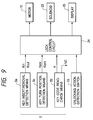
- the key device 1 has key insert/removal detection means 5a (see Fig. 9) for detecting the insertion and removal of the key; a key code read/check device 5b (see Fig. 9) for reading and checking an electrical code stored in the key; and key turn-position detection means 5c for detecting the turn position of the key.
- the key insert/removal detection means 5a When the key insert/removal detection means 5a outputs a key insert detection signal Kin when the key is inserted into the key rotor 3 and outputs a key removal detection signal Kout when the key is removed from the same.
- the thus-output signal is delivered to a lock control circuit 24 which will be described later.
- the key code read/check device 5b determines whether or not the inserted key is valid. If the key is valid, a valid key determination signal K is output. In contrast, if the key is invalid, an invalid key determination signal NG is output.
- the key turn-position detection means 5c outputs an "ACC" position detection signal Kacc when the key is turned past the "ACC" position.
- An operation section 5 is constituted from the key device 1, the key insert/removal detection means 5a, the key code read/check device 5b, and the key turn-position detection means 5c.
- Figs. 1 through 3 illustrate an actuator section 6 which is separated from the operation section 5 and is disposed in a required position in the vicinity of a steering shaft 7.
- An explanation will be given of this actuator section 6.
- a bracket 8 is provided outside and around the steering shaft 7.
- a substantially-prism-shaped lock member 10 is provided in a guide section 9 of the bracket 8 so as to be vertically movable in Fig. 1.
- a lower end 10e of the lock member 10 engages a lock groove 7a of the steering shaft 7 to thereby cause steering lock.
- the lower end 10e is actuated between a lock position where it engages the lock groove 7a and an unlock position where it disengages from the lock groove 7a.
- the lock member 10 is constantly forced toward the lock position where it locks the steering shaft 7 by means or a first spring 11; e.g., a compression spring, which is provided as a lock spring and is in contact with the upper end of the lock member 10.
- a stopper hole 10a is formed so as to pass through the lock member 10 in a transverse direction of the stopper 10.
- a retaining groove 10c which serves as an unlock-status hold engage section is formed in a side surface 10b of the stopper hole 10a.
- an actuation member 12 is disposed so as to be movable back and forth in the direction designated by arrow A and in the opposite direction (i.e., in the direction substantially crossing the direction in which the lock member 10 is moved).
- a rack 12a is formed on the lower surface of the actuation member 12.
- the actuation member 12 is provided with a lock stopper 13.
- This lock stopper 13 is connected to a second spring 14 which comprises a compression coil spring serving as an unlock spring in such a way as to be able to move in the direction designated by arrow A. More specifically, the lock stopper 13 is moved in the direction opposite to the direction A as a result of an engage section12a (see Fig. 2) engaging a mating section 13a of the lock stopper 13 when the actuation member 12 moves in the direction opposite to the direction A.
- a tapered cam surface 13b is formed in the end of the lock stopper 13 facing the lock member.
- the front end of the cam surface 13b is constantly inserted into the stopper hole 10a of the lock member 10.
- the side surface 12b of the actuation member 12 is substantially flush with the side surface 10b of the lock member 10.
- a tapered surface 12c and a plane surface 12d which is continually connected to an upper end of the tapered surface 12C is continually formed after the side surface 12b.
- the second spring 14 has stronger spring force than that of the first spring 11. Accordingly, if the actuation member 12 is moved in the direction designated by arrow A; i.e., one of the directions in which the actuation member 12 is actuated, the lock stopper 13 that undergoes the spring force of the second spring 14 moves the lock member 10 in a direction designated by arrow B against the spring force of the first spring member 11.
- the actuation member 12, the lock stopper 13, and the second spring 14 form a lock control mechanism 15. In this case, the actuation member 12 doubles as a disengage control member.
- a recess 9a for receiving the front end of the cam surface 13b of the lock stopper 13 is formed in the guide section 9.
- the bracket 8 is provided with a motor 16 which serves as electric actuation means and is made up of; e.g., a pulse motor.
- a worm gear 16a is attached to the rotary shaft of the motor 16.
- a worm wheel 17 is attached so as to mesh with the worm gear 16a.
- a pinion gear 18 which meshes with the rack 12a is attached to the end of a shaft 17a of the worm wheel 17.
- a gear mechanism 19 is formed from these elements.
- the lock member 10 has the side surface 10 on which the retaining groove 10c is formed and an unlock-status hold member 20 which extends across the side surface 12b of the actuation member 12.
- the center of the shaft of the unlock-status hold member 20 is pivotally supported by a shaft hold section 8b having a substantially U-shaped form.
- a spring member 21 is attached to one end 20a of the unlock status hold member 20.
- the spring member 21 comprises; e.g., a compression spring which serves as an unlock-status hold member and forces the end 20a toward the side surface 10b.
- the other end 20b of the unlock-status hold member 20 is relatively slid over the plane surface 12d from the side surface 12b of the actuation member 12 via the tapered surface 12c. Further, when the lock member 10 is moved in the direction designated by arrow B from the position shown in Figs. 1 and 2, the end 20a of the unlock-status hold member 20 fits into and engages the retaining groove 10c.
- a solenoid 22 which serves as electric unlocking means for pressing the end 20b toward the side 12b is provided on the end 20b of the unlock-status hold member 20.
- a plunger 22a is positioned so as to be opposite to the end 20b of the unlock-status hold member 20.
- An unlocking action detection switch 23 is provided in such a way that an actuator 23a is positioned in the vicinity of a notch 10d of the lock member 10.
- the unlocking action detection switch 23 is made up of a limit switch which serves as unlock-status detection means. In the state shown in Fig. 3, the unlock-status detection switch 23 is in an off state. When the lock member 10 is moved in the direction designated by arrow B, the unlock-status detection switch 23 is turned on.
- the unlock-status detection switch 23 Upon detection of the turn-on action of the lock member 10, the unlock-status detection switch 23 outputs an unlock detection signal Lout (see Fig. 9). In contrast, upon detection of the turn-off action of the lock member 10, the unlock-status detection switch 23 outputs a lock detection signal Lon.
- the lock control circuit 24 which serves as lock control means receives the valid key determination signal K from the operation section S, the key insertion detection signal Kin, the key removal detection signal Kout, the foregoing unlock detection signal Lout, or the lock detection signal Lon. Further the lock control circuit 24 is designed so as to control the motor 16 and the solenoid 22 in accordance with the thus-received signals.
- a display 25 is provided in the instrument panel (not shown) in order to indicate handle torque if the handle torque is exerted on the lock member 10. The display 25 is also controlled by the lock control circuit 24.
- Fig. 5A is a plan view showing the principal elements of the steering lock system
- Fig. 5B is a front view showing the principal elements shown in Fig. 5A.
- Figs. 1 through 3 illustrate the state of each of the principal elements when the key is not inserted into the steering lock system. More specifically, the lower end 10e of the lock member 10 is held in the lock position where the lock member engages and fits into the lock groove 7a of the steering shaft 7.
- the key insertion detection signal Kin is delivered to the lock control circuit 24. If the key is valid, the valid key determination signal K is delivered to the lock control circuit 24. When the key is turned past the "ACC" position, the "ACC" position detection signal Kacc is delivered to the lock control circuit 24.
- the lock control circuit 24 forwardly rotates the motor 16 by application of a given number of pulses.
- the pinion gear 18 is rotated in the direction designated by arrow C, so that the actuation member 12 is moved in the direction designated by arrow A.
- the lock stopper 13 is also moved in the same direction via the second spring member 14.
- the cam surface 13b of the lock stopper 13 forcefully raises the lock member 10 in the direction designated by arrow B against the spring force of the first spring 11. Accordingly, the lower end 10e of the lock member 10 is removed from the lock groove 7a of the steering shaft 7, and the lock member 10 arrives at the unlock position (see Fig. 5).
- the retaining groove 10c and the notch 10d of the lock member 10 are moved.
- the end 20a of the unlock-status hold member 20 engages and fits into the retaining groove 10c by means of the spring force of the spring 21, thereby holding the lock member 10 in the unlock position.
- the other end 20b of the unlock-status hold member 20 arrives as the plane surface 12d via the tapered surface 12c of the actuation member 12.
- the actuator 23a of the unlock detection switch 23 is moved to the side surface 10b from the notch 10d, so that the unlock detection switch 23 is turned on.
- the unlock detection signal Lout is then output.
- the motor 16 is driven (i.e., the key is inserted into the key rotor 3), and the unlock detection signal Lout is output after lapse of a given period of time.
- the lock control circuit 24 commences counting time after having received the "ACC" position detection signal Kacc. If the lock control circuit 24 receives the unlock detection signal Lout within a given period of time, the lock control circuits 24 determines that the lock member 10 is normally unlocked (i.e., there is no handle torque). In this case, an indication "Release Handle Torque" is not displayed on the display 25.
- the lock control circuit 24 receives the "LOCK” position detection signal Klock. Upon receipt of this signal, the lock control circuit 24 reversely rotates the motor 16 from its position shown in Fig. 5. As a result, the actuation member 12 is moved in the direction opposite to the direction designated by arrow A. In association with the movement of the actuation member 12, the lock stopper 13 is also moved in the same direction, whereby the majority of the lock member 10 is removed from the stopper hole 10a. This state is provided in Fig. 6.
- the end 20a of the unlock-status hold member 20 still remains engaged with the retaining groove 10c, and hence the lock member 10 is still held in the unlock position.
- the plane surface 12d of the actuation member 12 recedes with respect to the end 20b of the unlock-status hold member 20.
- the side surface 12b becomes separated from the end 20b.
- the unlock-status hold member 20 is allowed to pivot in a direction designated by arrow D.
- the key removal detection signal Kout is sent to the lock control circuit 24.
- the lock control circuit 24 actuates the solenoid 22 in the position shown in Fig. 6 so as to protrude the plunger 22a.
- the unlock-status hold member 20 is allowed to pivot in the direction designated by arrow D, and therefore the end 20a of the unlock-status hold member 20 is pushed to pivot in the direction designated by arrow D.
- the end 20a is removed and disengaged from the retaining groove 10c, whereby the lock member 10 moves to the lock position by means of the spring force of the first spring member 11.
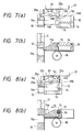
- the lock member 10 then fits into and engages the lock groove 7a of the steering shaft 7 (see Figs. 7A and 7B). Concurrently, the actuator 23a of the microswitch 23 engages the notch 10d, so that the microswitch 23 is turned off.
- the lock detection signal Lon is output and delivered to the lock control circuit 24. Upon detection of this signal, the lock control circuit 24 returns to its initial state.
- the lock control circuit 24 Upon receipt of the "ACC" position detection signal Kacc, the lock control circuit 24 commences counting time. If the lock control circuit 24 fails to receive the unlock detection signal Lout from the unlock detection switch 23 within a given period of time, the lock control circuit 24 determines that the lock member 10 undergoes handle torque. Accordingly, the indication “Release Handle Torque” is displayed on the display 25. Subsequently, when the driver releases the handle torque by turning the steering handle to a required extent, the lock member 10 becomes movable. The lock stopper 13 that undergoes the accumulated spring force of the second spring 14 is moved in the direction designated by arrow A, and the lock member 10 is raised against the spring force of the first spring member 11. As a result, the lock member 10 is moved to the unlock position.
- the operation section 5, such as a key device is separated from the actuator section 6, thereby resulting in an increase in the degree of freedom of layout of the actuator section 6.
- the actuator section 6 can be disposed around the driver's feet in the vicinity of the driver's seat, thereby resulting in an increase in the effective space.
- the strength of the actuator 6 can also be increased
- the actuation member 12 that doubles as the disengage control member prevents the disengaging action of the unlock-status hold member 20.
- the actuation member 12 allows the disengaging action of the unlock-status hold member 20. Accordingly, in the state where the lock member 10 should be locked, if the solenoid 22 that is the electric unlocking means is turned on, the unlock-status hold member 20 can be moved in a disengage direction without a hitch.
- the motor 16 if the motor 16 is actuated so as to perform unlocking operation, the displacement of the actuation member 12 is absorbed by the second spring 14, thereby preventing the motor 16 from locking. At this time, the spring force of the second spring 14 is accumulated, and the thus-accumulated spring force also acts on the lock member 10 via the lock stopper 13. Subsequently, if the handle torque is eliminated as a result of actuation of the steering handle by the driver, the lock member 10 moves to the unlock position. In this way, the motor 16 does not lock, and the lock member 10 can be moved to the unlock position only by one actuation.
- the actuation member 12 can move in the direction substantially crossing the direction in which the lock member 10 moves, and hence only small space is required in the direction in which the lock member 10 moves. Accordingly, the lock member can be reduced in size in the vertical direction shown in Fig. 1.
- Figs. 10 through 12 show a second embodiment of the present invention.
- the second embodiment is different from the first embodiment with regard to the structure of a lock control mechanism 31.
- a retaining groove 32b is formed on a side surface 32a of a lock member 32 which engages the lock groove 7a of the steering shaft 7.
- a rod 33 having a narrow width protrudes from an upper portion of the lock member 32, and a removal stopper 33a having a wide width is formed at the upper end of the rod 33.
- a frame-shaped actuation member 34 is attached to the rod 33 in such a way as to be movable back and forth in the same direction in which the lock member 32 moves.
- a spring receiver 35 is attached to the rod 33 within the actuation member 34 so s to be movable in the same direction in which the actuation member 34 moves.
- a first spring 36 comprising; e.g., a compression coil spring, is sandwiched between the upper end 34a and an upper wall 35a of the actuation member 34.
- the lock member 32 is forced toward the lock position (i.e., in a direction designated by arrow E) by means of the spring member 36.
- a second spring 37 which serves as an unlock spring and comprises; e.g., a compression spring, is interposed between the removal stopper 33a and the lower wall 35a of the spring receiver 35 for forcing the spring receiver 35 toward the direction designated by arrow E.
- the second spring 37 constantly holds the spring receiver 35 in contact with the removal stopper 33a of the rod 33 (i.e., in the limits of extent within the actuation member 13 to which the spring receiver 35 is moved in the direction designated by arrow E).
- the spring force of the second spring 37 is stronger than that of the first spring 36.
- a gear 34b is formed in the side surface of the actuation member 34.
- a gear 39 is attached to a rotary shaft 38a of a motor 38 which serves as electric actuation means.
- a gear 40 is interposed between the gear 39 and the gear 34b of the actuation member 34 so as to mesh with each other. Accordingly, as a result of rotation of the motor 38, the actuation member 34 is moved in the direction opposite to the direction designated by arrow E. In contrast, if the motor 38 is reversely rotated, the actuation member 34 is moved in the direction designated by arrow E.
- An unlock-status hold member 41 is provided so as to be movable in a direction designated by arrow F and in the direction opposite to the direction F.
- the unlock-status hold member 41 is connected to the key device 1 by way of a control wire (not shown). If the lock member 32 arrives at the unlock position (see Fig. 11), and the key is turned to the "ON" position from the “ACC” position, the unlock-status hold member 41 is actuated in the direction designated by arrow F, to thereby engage the retaining groove 32b.
- the steering lock system is provided with a lock control circuit (not shown).
- the key is not inserted into the key rotor 3. More specifically, a lower end 32c of the lock member 32 is in the lock position where it fits into and engages the lock groove 7a of the steering shaft 7. Further, the unlock-status hold member 41 is in close proximity to the side surface 32a of the lock member 32.
- the key insert detection signal Kin and the valid key determination signal K are delivered to the lock control circuit. If the key is turned past the "ACC" position, the "ACC" position detection signal Kacc is delivered to the lock control circuit.
- the lock control circuit forwardly rotates the motor 38 by application of a given number of pulses.
- the actuation member 34 is moved in the direction opposite to the direction designated by arrow E by way of the gears 39, 40, and 34b.
- the spring receiver 35 and the lock member 32 are moved in the same direction via the second spring 37.
- the lower end 32c of the lock member 32 disengages from the lock groove 7a of the steering shaft 7, and the lock member 32 arrives at the unlock position (see Fig. 11).
- the retaining groove 32b of the lock member 32 is positioned opposite the unlock-status hold member 41 (before the member 41 engages the groove 32b). If the key rotor 3 is turned from the "ACC" position to the "ON" position as a result or turning action of the key in this state, the unlock-status hold member 41 is moved in the direction designated by arrow F and fits into and engages the retaining groove 32b of the lock member 32. Consequently, the lock member 32 is held in the unlock state.
- the lock member 32 In the state where there is handle torque, the lock member 32 cannot move. If the motor 38 is actuated so as to perform unlocking operation (i.e., rotated in a forward direction) in this state, the lock member 32 still remains stationary. However, the spring receiver 35 and the actuation member 34 move against the spring force of the second spring 37. In other words, the displacement of the spring receiver 35 and the actuation member 34 is absorbed by means of the second spring 37, and hence the motor 38 is prevented from locking. At this time, the spring force of the second spring 37 is accumulated, and the thus-accumulated force acts on the lock member 32, as well (see Fig. 12). Subsequently, if the handle torque is eliminated by the driver, the lock member 32 becomes movable. The lock member 32 that undergoes the accumulated spring force of the second spring 37 is moved to the unlock position. As mentioned above, even in the second embodiment, the motor 38 is prevented from locking, and the lock member 32 can be moved to the unlock position only by one operation.
- the actuation member 34 can move in the same direction in which the lock member 32 moves, only small space is required in the direction in which the lock member 32 moves.
- the operation section such as a key device
- the actuator section is separated from the actuator section, thereby resulting in an increase in the degree of freedom of layout or the actuator section.
- the actuator section can be disposed around the driver's feet in the vicinity of the driver's seat, thereby resulting in an increase in the effective space. Further, it is ensured that the lock member can be held in an unlock position without being affected by electrical problems while an unlock-status hold member is actuated by means of electrical actuation means.
- the present invention provides the following advantageous results.
- an operation section such as a key device, is separated from the actuator section, thereby resulting in a high degree of freedom of layout of an actuator section.
- the actuator section can be disposed around the driver's feet in the vicinity of the driver's seat, thereby resulting in an increase in the effective space, thereby resulting in an increase in the effective space.
- a lock member can be actuated without locking electric actuation means, or without a need of actuation of the electric actuation means a plurality of times, even if the lock member is an inactive state due to handle torque when the lock member is unlocked.
- the actuation member can move in the direction substantially crossing the direction in which the lock member moves, and hence the space required in the direction in which the lock member moves can be reduced.
- the actuation member can move in the same direction in which the lock member moves, and hence the space required in the direction which crosses the direction in which the lock member moves an be reduced.
Landscapes
- Engineering & Computer Science (AREA)
- Mechanical Engineering (AREA)
- Lock And Its Accessories (AREA)
Abstract
Description
the actuator section further comprises
when the electric drive means is actuated so as to effect unlocking operation while the lock member undergoes handle torque, the displacement of the second actuation member is absorbed by the unlock spring, and the spring force is accumulated in the unlock spring.
when the electric drive means is actuated so as to effect unlocking operation while the lock member undergoes handle torque, the displacement of the spring receive member and the second actuation member is absorbed by the unlock spring, and the spring force is accumulated in the unlock spring.
the actuator section further comprises
Claims (4)
- A steering lock system comprising:an operation section of a key device;an actuator separated from the operation section and locking/unlocking a steering shaft in association with actuation of the operation section, the actuator section including:a lock member moved so as to be able to move between a position where the lock member locks the steering shaft and another position where the lock member unlocks the steering shaft;electric actuator controlled in accordance with actuation of the operation section;a lock control mechanism having an actuation member to be moved back and forth by the electric actuator, the lock control mechanism causing the lock member to lock/unlock in accordance with the back-and-forth movement of the actuation member; andan unlock spring member for forcing the lock member toward an unlock position,
wherein the lock control mechanism storing the spring force of the unlock spring while absorbing displacement of the actuation member when the electric drive member is actuated so as to effect unlocking operation while the lock member undergoes handle torque. - The steering lock system as defined in claim 1, wherein the lock control mechanism includes:a second actuator moved back and forth by the electric actuator in a direction which substantially crosses the direction of movement of the lock member; anda lock stopper provided so as to be able to move in the same direction in which the second actuator travels; which is actuated as a result of receipt of the force to move the second actuator in one direction via the unlock spring; which, as a result of actuation, moves the lock member to the unlock position; and which moves together with the second actuator in an integral manner when the second actuator is moved in another direction, to thereby move the lock member to a lock position, and
wherein when the electric drive member is actuated so as to effect unlocking operation while the lock member undergoes handle torque, the displacement of the second actuation member is absorbed by the unlock spring, and the spring force is accumulated in the unlock spring. - The steering lock system as defined in claim 1, wherein the lock control mechanism includes:a second actuator moved back and forth by the electric actuator in the same direction in which the lock member is moved; anda spring receive member moved in the same direction in which the second actuator ; which is provided in such a way that the unlock spring is interposed between the lock member and the spring receive member; and which moves together with the lock member in an integral manner via the unlock spring when the second actuator is moved in an unlock direction, and
wherein when the electric drive member is actuated so as to effect unlocking operation while the lock member undergoes handle torque, the displacement of the spring receive member and the second actuator is absorbed by the unlock spring, and the spring force is accumulated in the unlock spring. - A steering lock system comprising:an operation section of a key device;an actuator separated from the operation section and locking/unlocking a steering shaft in association with actuation of the operation section, the actuator including:a lock member moved so as to be able to move between a position where the lock member locks the steering shaft and another position where the lock member unlocks the steering shaft; and which is constantly forced toward the lock position by the lock spring and has an unlock-status hold engage section;a release mechanism for moving the lock member to the unlock position;an electric actuator actuating the release mechanism;an unlock-status hold member which engages the unlock-status hold engage section and holds the lock member in the unlock position by the spring force of an unlock spring member when the lock member arrives at the unlock position;an electric unlocking member controlled in accordance with the actuation of the operation section and actuating the unlock-status hold member in a disengage direction; anda disengage control member which prevents disengaging action of the unlock-states hold member when the lock member should be unlocked and allows the disengaging action of the unlock-status hold member when the lock member should be locked.
Applications Claiming Priority (6)
| Application Number | Priority Date | Filing Date | Title |
|---|---|---|---|
| JP301870/96 | 1996-11-13 | ||
| JP30187096 | 1996-11-13 | ||
| JP301868/96 | 1996-11-13 | ||
| JP30186896A JP3174006B2 (en) | 1996-11-13 | 1996-11-13 | Steering lock device |
| JP30187096A JP3174008B2 (en) | 1996-11-13 | 1996-11-13 | Steering lock device |
| JP30186896 | 1996-11-13 |
Publications (3)
| Publication Number | Publication Date |
|---|---|
| EP0844154A2 true EP0844154A2 (en) | 1998-05-27 |
| EP0844154A3 EP0844154A3 (en) | 1999-11-24 |
| EP0844154B1 EP0844154B1 (en) | 2003-05-14 |
Family
ID=26562905
Family Applications (1)
| Application Number | Title | Priority Date | Filing Date |
|---|---|---|---|
| EP19970119815 Expired - Lifetime EP0844154B1 (en) | 1996-11-13 | 1997-11-12 | Steering lock system |
Country Status (3)
| Country | Link |
|---|---|
| US (2) | US6125671A (en) |
| EP (1) | EP0844154B1 (en) |
| DE (1) | DE69721942T2 (en) |
Cited By (14)
| Publication number | Priority date | Publication date | Assignee | Title |
|---|---|---|---|---|
| GB2344090A (en) * | 1998-11-24 | 2000-05-31 | Tokai Rika Co Ltd | Steering lock mechanism |
| EP1029755A2 (en) * | 1999-02-15 | 2000-08-23 | Valeo GmbH & Co. Sicherheitssysteme | Arrangement for electrically locking the steering shaft of a steering device |
| EP1031478A2 (en) * | 1999-02-15 | 2000-08-30 | Valeo GmbH & Co. Sicherheitssysteme | Arrangement for locking the steering of a steering device |
| DE19923797A1 (en) * | 1999-05-25 | 2000-11-30 | Valeo Deutschland Gmbh & Co | Vehicle lock with anti-theft device |
| DE10022830A1 (en) * | 2000-05-10 | 2001-11-15 | Marquardt Gmbh | Locking device, especially for motor vehicle, has bolt whose state changes to non-securing state when being driven in locking direction only if drive is again driven in unlocking direction |
| DE10025488A1 (en) * | 2000-05-23 | 2001-12-06 | Daimler Chrysler Ag | Device for locking or unlocking a steering wheel of a motor vehicle |
| EP1174314A3 (en) * | 2000-07-18 | 2002-07-24 | Trw Italia S.P.A. | Electric vehicle steering lock |
| EP1380480A1 (en) * | 2002-07-12 | 2004-01-14 | Trw Italia S.P.A. | Electric steering lock |
| DE102004031238A1 (en) * | 2004-06-29 | 2006-02-09 | Daimlerchrysler Ag | Device for locking and / or unlocking a steering wheel of a motor vehicle |
| DE10051455C5 (en) * | 2000-10-17 | 2006-12-14 | Faurecia Autositze Gmbh & Co. Kg | Front seat for a two-door motor vehicle |
| DE102006059282A1 (en) | 2006-12-13 | 2008-06-19 | Huf Hülsbeck & Fürst Gmbh & Co. Kg | Arrangement for driving locking element for critical component, e.g. motor vehicle steering column or gear shift lever, has locking element contact surface that interacts with first contact surface to move locking element to position |
| EP2319737A1 (en) * | 2008-08-05 | 2011-05-11 | Alpha Corporation | Steering lock device |
| CN103129521A (en) * | 2011-11-28 | 2013-06-05 | 株式会社有信 | Electric steering lock device |
| EP3287330A1 (en) | 2016-08-23 | 2018-02-28 | HUF Hülsbeck & Fürst GmbH & Co. KG | Blocking device for the steering column of a motor vehicle and steering column with the blocking device |
Families Citing this family (46)
| Publication number | Priority date | Publication date | Assignee | Title |
|---|---|---|---|---|
| DE19752519A1 (en) * | 1997-11-27 | 1999-06-10 | Bosch Gmbh Robert | Locking device for steering of motor vehicles |
| DE19906267C2 (en) * | 1999-02-15 | 2001-03-15 | Valeo Deutschland Gmbh & Co | Device for electrically locking the steering spindle of a motor vehicle steering device |
| US6442985B1 (en) * | 1999-06-11 | 2002-09-03 | Nissan Motor Co., Ltd. | Lock apparatus and lock system |
| US6324878B1 (en) * | 1999-08-26 | 2001-12-04 | Methode Electronics, Inc. | Steering lock device with safety system |
| DE10041984B4 (en) * | 2000-08-26 | 2006-02-23 | Valeo Sicherheitssysteme Gmbh | Device for locking the steering spindle of a vehicle |
| US6516640B2 (en) * | 2000-12-05 | 2003-02-11 | Strattec Security Corporation | Steering column lock apparatus and method |
| US6571587B2 (en) * | 2001-01-09 | 2003-06-03 | Strattec Security Corporation | Steering column lock apparatus and method |
| DE10103182B4 (en) * | 2001-01-24 | 2012-09-27 | Valeo Sicherheitssysteme Gmbh | locking device |
| JP2002234419A (en) * | 2001-02-09 | 2002-08-20 | Tokai Rika Co Ltd | Electronic steering lock mechanism |
| JP2003112602A (en) * | 2001-10-04 | 2003-04-15 | Tokai Rika Co Ltd | Electronic vehicle theft prevention device |
| WO2003099613A2 (en) * | 2002-05-23 | 2003-12-04 | Methode Electronics, Inc. | Steering lock device |
| DE10237985B4 (en) * | 2002-08-14 | 2006-01-19 | Karl Simon Gmbh & Co. Kg | lock |
| DE10247803B3 (en) * | 2002-10-14 | 2004-01-29 | Huf Hülsbeck & Fürst Gmbh & Co. Kg | Device for locking the steering spindle of a motor vehicle |
| JP4084200B2 (en) * | 2003-01-10 | 2008-04-30 | 株式会社東海理化電機製作所 | Electric steering lock device |
| JP4038132B2 (en) * | 2003-01-31 | 2008-01-23 | 株式会社東海理化電機製作所 | Electric steering lock device |
| DE10320154B3 (en) * | 2003-05-06 | 2005-02-17 | Huf Hülsbeck & Fürst Gmbh & Co. Kg | Device for locking the steering spindle of a motor vehicle |
| FR2854855B1 (en) * | 2003-05-15 | 2006-05-05 | Nacam | ELECTRICAL LOCK FOR A MOTOR VEHICLE STEERING SHAFT |
| JP4184874B2 (en) * | 2003-06-11 | 2008-11-19 | 株式会社東海理化電機製作所 | Steering lock device |
| JP2005014681A (en) * | 2003-06-24 | 2005-01-20 | Nsk Ltd | Steering column device for vehicle |
| US20050120761A1 (en) * | 2003-12-03 | 2005-06-09 | Rouleau James E. | Column assembly of a vehicle having a steering column to be locked and unlocked |
| US7140213B2 (en) | 2004-02-21 | 2006-11-28 | Strattec Security Corporation | Steering column lock apparatus and method |
| JP4490734B2 (en) * | 2004-05-24 | 2010-06-30 | 株式会社アルファ | Electric steering lock device |
| FR2871759B1 (en) * | 2004-06-17 | 2007-10-19 | Valeo Securite Habitacle Sas | ANTI-THEFT ANTI-THEFT DEVICE WITH INSERABLE LOCK, IN PARTICULAR FOR A MOTOR VEHICLE |
| JP4348245B2 (en) * | 2004-07-08 | 2009-10-21 | 株式会社東海理化電機製作所 | Steering lock device |
| FR2873075B1 (en) * | 2004-07-13 | 2006-10-20 | Nacam France Sas | ELECTRICAL LOCK OFFSET OF MOTOR VEHICLE STEERING SHAFT |
| JP4460972B2 (en) * | 2004-08-03 | 2010-05-12 | 株式会社東海理化電機製作所 | Steering lock device |
| US7730752B2 (en) * | 2006-03-13 | 2010-06-08 | Kawasaki Jukogyo Kabushiki Kaisha | Theft prevention apparatus for leisure vehicle |
| JP4980853B2 (en) * | 2006-11-10 | 2012-07-18 | 株式会社アルファ | Electric steering lock device |
| DE102007002451A1 (en) * | 2007-01-11 | 2008-07-17 | Huf Hülsbeck & Fürst Gmbh & Co. Kg | Device for controlling a locking member |
| DE102007018218A1 (en) * | 2007-04-16 | 2008-10-23 | Huf Hülsbeck & Fürst Gmbh & Co. Kg | Device for controlling a locking member |
| DE102007034481A1 (en) * | 2007-07-20 | 2009-01-22 | Huf Hülsbeck & Fürst Gmbh & Co. Kg | Locking device with locking part |
| KR100916343B1 (en) * | 2007-07-30 | 2009-09-11 | 동아대학교 산학협력단 | Apparatus and Method for Starting an Engine of Automobile using Start-Button |
| ATE553010T1 (en) * | 2007-12-31 | 2012-04-15 | Valeo Sicherheitssysteme Gmbh | MOTORIZED STEERING LOCK DEVICE |
| JP5020153B2 (en) * | 2008-04-18 | 2012-09-05 | 株式会社ユーシン | Electric steering lock device |
| JP5385724B2 (en) * | 2008-08-29 | 2014-01-08 | 株式会社アルファ | Steering lock device |
| JP5118079B2 (en) * | 2009-02-03 | 2013-01-16 | 株式会社東海理化電機製作所 | Key device |
| FR2952332B1 (en) * | 2009-11-06 | 2013-11-29 | Valeo Securite Habitacle | ANTI-THEFT DEVICE FOR THE STEERING COLUMN OF A VEHICLE WITH HIGH CONDAMNATION ENSURED BY INTERMEDIATE ROCKET |
| US8424348B2 (en) * | 2010-01-27 | 2013-04-23 | Strattec Security Corporation | Steering lock |
| US20140069224A1 (en) | 2012-09-07 | 2014-03-13 | Strattec Security Corporation | Steering lock |
| PL2479073T3 (en) * | 2011-01-21 | 2014-06-30 | Valeo Sicherheitssysteme Gmbh | Steering-wheel antitheft device for an automobile |
| JP5956780B2 (en) * | 2012-03-01 | 2016-07-27 | 株式会社アルファ | Electric steering lock device |
| DE102016108565A1 (en) * | 2016-05-10 | 2017-11-16 | Huf Hülsbeck & Fürst Gmbh & Co. Kg | Implementation element for an electric steering lock |
| WO2018042236A1 (en) * | 2016-09-02 | 2018-03-08 | Hardcore Automotive Locking Technologies (Pty) Ltd | A vehicle anti-theft device |
| TWI686321B (en) * | 2017-05-23 | 2020-03-01 | 英屬開曼群島商睿能創意公司 | Lock apparatus and vehicle using the same |
| JP2018202923A (en) * | 2017-05-31 | 2018-12-27 | 株式会社東海理化電機製作所 | Locking unit |
| CA3130819A1 (en) | 2019-04-05 | 2020-10-08 | Dormakaba Usa Inc. | Electronic lock |
Family Cites Families (21)
| Publication number | Priority date | Publication date | Assignee | Title |
|---|---|---|---|---|
| GB144476A (en) * | 1919-06-16 | 1920-06-17 | Edward Joseph Pyke | An improved locking device for motor cars and similar vehicles |
| US1466537A (en) * | 1922-02-18 | 1923-08-28 | Charles M Mccarthy | Lock |
| US1736900A (en) * | 1928-01-07 | 1929-11-26 | Arthur H Hough | Steering-wheel lock for automobiles |
| US2890581A (en) * | 1955-11-23 | 1959-06-16 | Gen Motors Corp | Transmission lock |
| US2964935A (en) * | 1958-12-01 | 1960-12-20 | Lombardi Mario | Automobile combination ignition starter |
| US3610004A (en) * | 1969-09-30 | 1971-10-05 | Gen Motors Corp | Parking lock for transmissions |
| JPS4810355Y1 (en) * | 1970-04-03 | 1973-03-19 | ||
| US4318288A (en) * | 1979-04-30 | 1982-03-09 | Rifat Sultan A | Steering column lock |
| DE3206434A1 (en) * | 1982-02-23 | 1983-09-22 | Audi Nsu Auto Union Ag, 7107 Neckarsulm | Locking system for motor vehicles |
| DE3344411C2 (en) * | 1983-12-08 | 1985-10-10 | Hülsbeck & Fürst GmbH & Co KG, 5620 Velbert | Steering and ignition locks for motor vehicles |
| US4643009A (en) * | 1984-12-27 | 1987-02-17 | Kokusan Kinzoku Kogyo Kabushiki Kaisha | Steering lock arrangement |
| FR2594877B1 (en) * | 1986-02-24 | 1991-06-21 | Fichet Bauche | DEVICE FOR LOCKING AND UNLOCKING ANY BODY, SUCH AS FOR EXAMPLE A BAR HAVING PENES |
| US5136284A (en) * | 1987-03-06 | 1992-08-04 | Mitsubishi Denki Kabushiki Kaisha | Security system |
| JPS6480678A (en) * | 1987-05-30 | 1989-03-27 | Aisin Seiki | Steering locking device |
| JPH0791426B2 (en) * | 1987-09-17 | 1995-10-04 | 東燃化学株式会社 | Thermoplastic resin composition |
| JPH01175543A (en) | 1987-12-28 | 1989-07-12 | Aisin Seiki Co Ltd | Lock device for steering |
| US4907427A (en) * | 1988-12-27 | 1990-03-13 | Armstrong Ennels D | Steering wheel shaft lock assembly |
| GB9105578D0 (en) * | 1991-03-15 | 1991-05-01 | Tobin Mark I | Security system |
| US5634358A (en) * | 1994-03-15 | 1997-06-03 | Fort Lock Corporation | Motorcycle ignition switch and steering lock |
| US5685183A (en) * | 1994-07-19 | 1997-11-11 | Kabushiki Kaisha Tokai Rika Denki Seisakusho | Vehicle locking device |
| US5454238A (en) * | 1994-07-25 | 1995-10-03 | General Motors Corporation | Anti-theft apparatus for motor vehicle steering column |
-
1997
- 1997-11-12 US US08/967,899 patent/US6125671A/en not_active Expired - Fee Related
- 1997-11-12 EP EP19970119815 patent/EP0844154B1/en not_active Expired - Lifetime
- 1997-11-12 DE DE1997621942 patent/DE69721942T2/en not_active Expired - Lifetime
-
1999
- 1999-12-22 US US09/468,901 patent/US6295848B1/en not_active Expired - Fee Related
Non-Patent Citations (1)
| Title |
|---|
| None |
Cited By (27)
| Publication number | Priority date | Publication date | Assignee | Title |
|---|---|---|---|---|
| GB2344090B (en) * | 1998-11-24 | 2002-03-27 | Tokai Rika Co Ltd | Steering lock apparatus |
| GB2344090A (en) * | 1998-11-24 | 2000-05-31 | Tokai Rika Co Ltd | Steering lock mechanism |
| DE19956300B4 (en) * | 1998-11-24 | 2006-04-20 | Kabushiki Kaisha Tokai Rika Denki Seisakusho | Steering lock device |
| EP1029755A2 (en) * | 1999-02-15 | 2000-08-23 | Valeo GmbH & Co. Sicherheitssysteme | Arrangement for electrically locking the steering shaft of a steering device |
| EP1031478A2 (en) * | 1999-02-15 | 2000-08-30 | Valeo GmbH & Co. Sicherheitssysteme | Arrangement for locking the steering of a steering device |
| EP1029755A3 (en) * | 1999-02-15 | 2001-01-17 | Valeo GmbH & Co. Sicherheitssysteme | Arrangement for electrically locking the steering shaft of a steering device |
| EP1031478A3 (en) * | 1999-02-15 | 2001-08-16 | Valeo GmbH & Co. Sicherheitssysteme | Arrangement for locking the steering of a steering device |
| DE19923797A1 (en) * | 1999-05-25 | 2000-11-30 | Valeo Deutschland Gmbh & Co | Vehicle lock with anti-theft device |
| DE10022830B4 (en) * | 2000-05-10 | 2012-05-31 | Marquardt Gmbh | Locking device, in particular for a motor vehicle |
| DE10022830A1 (en) * | 2000-05-10 | 2001-11-15 | Marquardt Gmbh | Locking device, especially for motor vehicle, has bolt whose state changes to non-securing state when being driven in locking direction only if drive is again driven in unlocking direction |
| DE10025488C2 (en) * | 2000-05-23 | 2003-01-23 | Daimler Chrysler Ag | Device for locking or unlocking a steering wheel of a motor vehicle |
| EP1157907A3 (en) * | 2000-05-23 | 2004-04-14 | Marquardt GmbH | Device for locking or unlocking of a motor vehicle steering wheel |
| DE10025488A1 (en) * | 2000-05-23 | 2001-12-06 | Daimler Chrysler Ag | Device for locking or unlocking a steering wheel of a motor vehicle |
| EP1174314A3 (en) * | 2000-07-18 | 2002-07-24 | Trw Italia S.P.A. | Electric vehicle steering lock |
| DE10051455C5 (en) * | 2000-10-17 | 2006-12-14 | Faurecia Autositze Gmbh & Co. Kg | Front seat for a two-door motor vehicle |
| EP1380480A1 (en) * | 2002-07-12 | 2004-01-14 | Trw Italia S.P.A. | Electric steering lock |
| DE102004031238B4 (en) * | 2004-06-29 | 2015-03-12 | Huf Hülsbeck & Fürst Gmbh & Co. Kg | Device for locking and / or unlocking a steering wheel of a motor vehicle |
| DE102004031238A1 (en) * | 2004-06-29 | 2006-02-09 | Daimlerchrysler Ag | Device for locking and / or unlocking a steering wheel of a motor vehicle |
| DE102006059282A1 (en) | 2006-12-13 | 2008-06-19 | Huf Hülsbeck & Fürst Gmbh & Co. Kg | Arrangement for driving locking element for critical component, e.g. motor vehicle steering column or gear shift lever, has locking element contact surface that interacts with first contact surface to move locking element to position |
| DE102006059282B4 (en) | 2006-12-13 | 2018-07-19 | Huf Hülsbeck & Fürst Gmbh & Co. Kg | Device for controlling a locking member |
| EP2319737A1 (en) * | 2008-08-05 | 2011-05-11 | Alpha Corporation | Steering lock device |
| EP2319737A4 (en) * | 2008-08-05 | 2013-06-12 | Alpha Corp | Steering lock device |
| CN103129521A (en) * | 2011-11-28 | 2013-06-05 | 株式会社有信 | Electric steering lock device |
| CN103129521B (en) * | 2011-11-28 | 2016-08-03 | 株式会社有信 | Electric steering-lock device |
| EP3287330A1 (en) | 2016-08-23 | 2018-02-28 | HUF Hülsbeck & Fürst GmbH & Co. KG | Blocking device for the steering column of a motor vehicle and steering column with the blocking device |
| DE102016115643A1 (en) | 2016-08-23 | 2018-03-01 | Huf Hülsbeck & Fürst Gmbh & Co. Kg | Locking device for a steering column of a motor vehicle and steering column with the locking device |
| EP3659874A1 (en) | 2016-08-23 | 2020-06-03 | Huf Hülsbeck & Fürst GmbH & Co. KG | Blocking device for the steering column of a motor vehicle and steering column with the blocking device |
Also Published As
| Publication number | Publication date |
|---|---|
| EP0844154A3 (en) | 1999-11-24 |
| DE69721942T2 (en) | 2004-05-19 |
| EP0844154B1 (en) | 2003-05-14 |
| US6295848B1 (en) | 2001-10-02 |
| DE69721942D1 (en) | 2003-06-18 |
| US6125671A (en) | 2000-10-03 |
Similar Documents
| Publication | Publication Date | Title |
|---|---|---|
| US6125671A (en) | Steering lock system | |
| KR101506365B1 (en) | Steering lock device | |
| US5615564A (en) | Door locking device with an antitheft mechanism | |
| US6233986B1 (en) | Steering lock apparatus | |
| EP2319737B1 (en) | Steering lock device | |
| KR20070012625A (en) | Mechanism for starting a vehicle engine by means of an electronic key, and key to be used therefor | |
| CA1254397A (en) | Automobile door locking systems | |
| US5027931A (en) | Brake/shift interlock for an automatic transmission shift control mechanism | |
| US6824177B1 (en) | Locking system for the door of a motor vehicle | |
| US20050034493A1 (en) | Locking system for motor vehicles | |
| EP2694336B1 (en) | Steering lock device | |
| EP1462325B1 (en) | Ignition lock system for an automobile | |
| KR20010015286A (en) | Vehicle shift lever device | |
| US20200122682A1 (en) | Locking device, in particular, for a motor vehicle | |
| JPH0257187B2 (en) | ||
| US6941781B2 (en) | Electrically-operated steering lock device | |
| DE102004063240B4 (en) | Steering lock for personal identification card system | |
| EP0336219A2 (en) | Steering locking apparatus | |
| JP3174006B2 (en) | Steering lock device | |
| US5065604A (en) | Ignition interlock system | |
| JP3174008B2 (en) | Steering lock device | |
| JP2001018675A (en) | Shift lever device | |
| KR20070012481A (en) | Actuating module for a motor vehicle | |
| US7788955B2 (en) | Ignition switch and steering lock device for motor vehicles | |
| DE10300572A1 (en) | Door handle and locking system for a vehicle door |
Legal Events
| Date | Code | Title | Description |
|---|---|---|---|
| PUAI | Public reference made under article 153(3) epc to a published international application that has entered the european phase |
Free format text: ORIGINAL CODE: 0009012 |
|
| AK | Designated contracting states |
Kind code of ref document: A2 Designated state(s): DE GB |
|
| AX | Request for extension of the european patent |
Free format text: AL;LT;LV;MK;RO;SI |
|
| PUAL | Search report despatched |
Free format text: ORIGINAL CODE: 0009013 |
|
| AK | Designated contracting states |
Kind code of ref document: A3 Designated state(s): AT BE CH DE DK ES FI FR GB GR IE IT LI LU MC NL PT SE |
|
| AX | Request for extension of the european patent |
Free format text: AL;LT;LV;MK;RO;SI |
|
| 17P | Request for examination filed |
Effective date: 20000210 |
|
| AKX | Designation fees paid |
Free format text: DE GB |
|
| 17Q | First examination report despatched |
Effective date: 20011012 |
|
| GRAG | Despatch of communication of intention to grant |
Free format text: ORIGINAL CODE: EPIDOS AGRA |
|
| GRAG | Despatch of communication of intention to grant |
Free format text: ORIGINAL CODE: EPIDOS AGRA |
|
| GRAH | Despatch of communication of intention to grant a patent |
Free format text: ORIGINAL CODE: EPIDOS IGRA |
|
| GRAH | Despatch of communication of intention to grant a patent |
Free format text: ORIGINAL CODE: EPIDOS IGRA |
|
| GRAA | (expected) grant |
Free format text: ORIGINAL CODE: 0009210 |
|
| AK | Designated contracting states |
Designated state(s): DE GB |
|
| REG | Reference to a national code |
Ref country code: GB Ref legal event code: FG4D |
|
| REF | Corresponds to: |
Ref document number: 69721942 Country of ref document: DE Date of ref document: 20030618 Kind code of ref document: P |
|
| PLBE | No opposition filed within time limit |
Free format text: ORIGINAL CODE: 0009261 |
|
| STAA | Information on the status of an ep patent application or granted ep patent |
Free format text: STATUS: NO OPPOSITION FILED WITHIN TIME LIMIT |
|
| 26N | No opposition filed |
Effective date: 20040217 |
|
| PGFP | Annual fee paid to national office [announced via postgrant information from national office to epo] |
Ref country code: GB Payment date: 20081112 Year of fee payment: 12 |
|
| GBPC | Gb: european patent ceased through non-payment of renewal fee |
Effective date: 20091112 |
|
| PG25 | Lapsed in a contracting state [announced via postgrant information from national office to epo] |
Ref country code: GB Free format text: LAPSE BECAUSE OF NON-PAYMENT OF DUE FEES Effective date: 20091112 |
|
| PGFP | Annual fee paid to national office [announced via postgrant information from national office to epo] |
Ref country code: DE Payment date: 20121107 Year of fee payment: 16 |
|
| REG | Reference to a national code |
Ref country code: DE Ref legal event code: R119 Ref document number: 69721942 Country of ref document: DE Effective date: 20140603 |
|
| PG25 | Lapsed in a contracting state [announced via postgrant information from national office to epo] |
Ref country code: DE Free format text: LAPSE BECAUSE OF NON-PAYMENT OF DUE FEES Effective date: 20140603 |