This invention relates to a method, device, and
video signal recording medium which are made capable of
anti-duplication control, for example, in the case that a
video signal recorded on a recording medium is played back
and transmitted together with information for preventing
duplication, and the recording of the transmitted and
received video signal on another recording medium is
inhibited or restricted, by way of a method involving a video
signal on which the additional information is superimposed is
outputted, the superimposed additional information is
extracted from the received signal, and the extracted
additional information is utilized to prevent duplication.
VTR (Video Tape recording devices) has been
popularized in daily life, and many kinds of software which
can be played back on a VTR are available. Digital VTR or
DVD (Digital Video Disks) playback devices have been
available practically now, and provide images and sound of
exceptionally high quality.
On the other hand, there is, however, a problem in
that this great abundance of software can be copied without
restriction, and several methods have already been proposed
to inhibit duplication.
For example, for a VTR which outputs an analog
video signal, one method to prevent copying uses a difference
in the AGC (Automatic Gain Control) system, or in the APC
(Automatic Phase Control) system, of the VTR recording device
and of a monitor receiver for displaying the image.
When the method which utilizes the difference in
AGC system, in which a VTR performs AGC using a pseudo sync
signal inserted in the video signal and a monitor receiver
employs a different AGC system not using the pseudo sync
signal, is used, a very high level pseudo sync signal is
inserted in the video signal supplied from the playback VTR
and the video signal with insertion is outputted to the
recording VTR as an AGC sync signal.
When the method which utilizes the difference in
APC characteristics, in which a VTR performs APC using the
phase of the colour burst signal itself in the video signal
and a monitor receiver employs an APC system different from
that of the VTR, is used, the phase of the colour burst of
the video signal supplied from the playback VTR to the
recording VTR is inverted partially.
As the result, the monitor receiver which receives
the analog video signal from the playback VTR plays back the
image correctly without being affected by the pseudo sync
signal in AGC or the partial phase inversion of the colour
burst signal used for APC.
On the other hand, in a VTR, which is supplied with
the analog video signal from the playback VTR into which
pseudo sync signals have been inserted or which has been
subjected to colour burst signal phase inversion control as
described herein above, for receiving such analog video
signal and for recording the analog video signal on a
recording medium, proper gain control or phase control based
on the input signal cannot be performed, and so the video
signal is not correctly recorded. Even if this signal is
played back, therefore, normal picture and sound cannot be
obtained.
In the case of a digitized video signal, for
example, in a digital VTR, an anti-duplication signal or an
anti-duplication control signal comprising, for example, a
duplication ranking control code, is added as digital data to
the video signal and recorded on the recording medium, so as
to prevent or control duplication of the image.
In this case, the playback digital VTR reads the
video signal, audio signal and anti-duplication control
signal, and supplies them as digital or analog data to a
recording digital VTR.
In the digital VTR being used as a recording
device, the anti-duplication control signal is extracted from
the supplied playback signal, and recording of the playback
signal is then controlled based on the anti-duplication
control signal. For example, when the anti-duplication
control signal comprises an anti-duplication signal, the
recording VTR does not perform recording.
Alternatively, when the anti-duplication control
signal comprises a duplication ranking control code,
recording is controlled by this ranking control code. For
example, when the duplication ranking code limits duplication
to one copy, the digital VTR used for recording adds this
anti-duplication code before recording the video signal and
audio signal on the recording medium as digital data. It is
thereafter impossible to duplicate the video signal from the
copy.
Hence, in the case of a digital connection when the
video signal, the audio signal, and the anti-duplication
control signal used as digital signals are supplied to the
digital VTR used as a recording device, anti-duplication
control is performed on the recording side using the
anti-duplication control signal by supplying this signal to
the digital VTR as digital data.
However, in the case of an analog connection where
the video signal and audio signal are supplied as analog
signals to a digital VTR used as a recording device (the
digital VTR performs A/D conversion), D/A conversion of a
signal to be supplied to the recording device causes the loss
of the anti-duplication control signal because the
anti-duplication control signal is not superimposed on the
analog information signal such as a video signal and audio
signal. Hence, in the case of an analog connection, an
anti-duplication control signal must be added to the D/A
converted image or sound signal, and this addition causes
deterioration of the video signal and audio signal.
It is, therefore, difficult to add an
anti-duplication control signal and to extract it in the
recorder for the purpose of anti-duplication control, without
causing deterioration of the D/A converted video signal or
audio signal.
Conventionally, therefore, in the case of an analog
connection, duplication was prevented by an anti-duplication
method using a difference in the AGC, or a difference in APC
characteristics, between the VTR and the monitor receiver
However, in some cases, when anti-duplication is
prevented using the above-mentioned difference in the AGC or
a difference in APC characteristics between the VTR and the
monitor receiver, depending on the type of AGC or APC
characteristics in the recording side, the video signal may
nevertheless be correctly recorded, in this case, it might
happen that duplication cannot be prevented, or that the
reproduced image on the monitor receiver is distorted.
Further, it is troublesome to change over the
anti-duplication method depending on whether there is an
analog connection or a digital connection.
To solve such problem, an anti-duplication method
in which a spectrally spread anti-duplication control signal
is superimposed on a video signal is supposed to be useful as
a method which can be used for both digital connections and
analog connections without deterioration of the image or
sound which is played back.
According to this method, a PN (Pseudorandom Noise)
sequence code (referred to hereinafter as PN code) used as a
spread code is generated with a sufficiently short period and
spectrally spread by multiplying it by the anti-duplication
control signal. In this way, a narrow-bandwidth high-level
anti-duplication control signal is converted to a wide-band
low-level signal which does not affect the video signal or
sound signal. This spectrally spread anti-duplication
control signal is then superimposed on the analog video
signal, and recorded on a recording medium. In this case,
the signal to be recorded on a recording medium may be an
analog signal or a digital signal.
In the case that the recording medium does not
carry a recorded video signal on which a spectrally spread
anti-duplication control signal is superimposed but the
recording medium carries a recorded video signal on which an
anti-duplication control signal is recorded together with the
video signal in the different other system, in the playback
device, the anti-duplication control signal is extracted from
the playback signal, spectrally spread, and superimposed on
the video signal to be outputted.
On the other hand, in the recording device side,
phase control is performed on the input video signal so that
a PN code having the same generation timing and phase as
those of the PN code used for spectrally spreading the
anti-duplication control signal, and inversion spectral
spreading is performed for extracting the original
anti-duplication control signal by multiplying the video
signal on which the spectrally spread anti-duplication
control signal is superimposed by the PN code. Hence, the
duplication prevention control is performed based on the
anti-duplication control signal extracted by inversion
spectral spreading.
In this way, the anti-duplication control signal is
spectrally spread and superimposed on the video signal as a
wide-band low-level signal. It is therefore difficult for a
person who wishes to illegally duplicate the video signal, to
remove the anti-duplication control signal which is
superimposed on it.
However, it is possible to detect and use the
superimposed anti-duplication control signal by inversion
spectral spreading. This anti-duplication control signal is
therefore supplied to the recording device together with the
video signal. In the recording side, the anti-duplication
control signal is detected, and duplication is consistently
controlled according to the detected anti-duplication control
signal.
According to this method, as described herein
above, the spectrally spread anti-duplication control signal
is superimposed as a wide band, low level signal on the video
signal, but it must be superimposed at a low level so that
S/N ratio is higher than that of the video signal in order
for the video signal not to cause deterioration of the video
signal.
To superimpose the spectrally spread
anti-duplication control signal at a low level so that S/N
ratio is higher than that of the video signal, and to be able
to detect the anti-duplication control signal superimposed on
the video signal in the recording device, the number of the
PN codes (PN code length) required to spectrally spread a 1
bit anti-duplication control signal must be sufficiently
large. The PN code length per bit of the anti-duplication
control signal may also be expressed as a spread gain (spread
factor) which is the ratio (T/TC) of a time width T per bit
of the anti-duplication control signal to a time width TC of
one part (one chip) of the PN code. As described
hereinafter, this spread gain is obtained corresponding to
the S/N ratio of the information signal on which the
anti-duplication control signal is superimposed, in this
case, corresponding to the S/N ratio of the video signal.
For example, when the S/N ratio of the video signal
on which the anti-duplication control signal is superimposed
is 50 dB, the anti-duplication control signal which is
spectrally spread and superimposed on the video signal must
be superimposed at a low level so that S/N ratio is higher
than 50 dB, which is the S/N ratio of the video signal.
Also, in order to detect the anti-duplication control signal
superimposed on the video signal, its S/N ratio must be
sufficient for the spectrally spread signal to be fully
demodulated. If this S/N ratio is 10 dB, a spread gain of 60
dB (S/N ratio of 50 dB for video signal) + (S/N ratio of 10
dB necessary for detection) is required. In this case, the
PN code length per bit of the anti-duplication control signal
is 1 million code length.
In the case of a video signal on which a spectrally
spread additional information is superimposed, spread gain
can not be made small because of significant adverse effect
of the superimposed additional information on the video
signal and necessary S/N ratio required for extraction of the
superimposed additional information.
To cope with this problem alternatively, if a large
number of spread codes required for spectrally spreading an
additional information per one bit is used, it takes a long
time to performing inversion spectral spreading for
extracting the spectrally spread additional information, and
adequate control corresponding to the additional information
superimposed on a video signal can not be performed.
For example, in the case of the anti-duplication
control signal of inhibition of duplication, a video signal
recording device which records a video signal until an
anti-duplication control signal is detected completes
recording of the supplied video signal before the
anti-duplication control signal is detected.
Also in the case of the anti-duplication control
signal of permission of duplication, a vide signal recording
device which does not record a video signal until an
anti-duplication control signal is detected can not record
the video signal supplied before the anti-duplication control
signal is detected.
In view of the above-mentioned problem, it is an
object of the present invention to provide a method, device,
and recording medium which are capable of extracting rapidly
and correctly a spectrally spread anti-duplication control
signal superimposed on a video signal to eliminate the
above-mentioned problem.
To solve the above-mentioned problem, a video
signal transmission method as defined in claim 1 is provided
in accordance with which in a method for transmitting a
spectrally spread additional information superimposed on a
video signal, wherein the spectrally spread additional
information is superimposed on every second interval of
correlative video signal intervals.
A superimposed information extraction method as
defined in claim 5 is a method for extracting additional
information from a video signal on which the spectrally
spread additional information is superimposed every second
interval of correlative video signal intervals, wherein the
additional information superimposed on the video signal is
extracted by performing inversion spectral spreading with aid
of the same spreading code as used for spectrally spreading
the additional information for the interval of the
correlative video signal intervals on which the spectrally
spread additional information is superimposed, and on the
other hand, with aid of a spreading code having the polarity
different from the spreading code used for spectral spreading
for the interval on which the spectrally spread additional
information is not superimposed.
A superimposed information extraction method as
defined in claim 9 is a method for extracting additional
information from a video signal on which the spectrally
spread additional information is superimposed every second
interval of correlative video signal intervals, wherein the
spectrally spread additional information is extracted by
determining the difference between the interval of the
correlative video signal intervals on which the spectrally
spread additional information is superimposed and the
interval on which the spectrally spread additional
information is not superimposed, and followed by inversion
spectral spreading of the resultant difference.
According to the video signal transmission method
in accordance with the present invention, a spectrally spread
anti-duplication control signal is superimposed on
correlative video signal predetermined interval of the video
signal, for example, every second vertical interval (field),
and transmitted.
According to the superimposed information
extraction method in accordance with the present invention,
the spread code having different polarity is generated
depending on the video signal on which the spectrally spread
anti-duplication control signal is superimposed
intermittently every second interval of the correlative video
signal predetermined intervals as described herein above, in
this case, every second field, that is, depending on which
type of video signal interval is involved, the video signal
interval on which the additional information is superimposed
or the video signal interval on which the additional
information is not superimposed.
In detail as described herein above, the same
spread code as used for spectrally spreading the additional
information is generated for the field on which the
additional information is superimposed. On the other hand, a
spread code having the opposite polarity to that of the
spread code used for spectral spreading is generated for the
field on which the additional information is not
superimposed.
As described herein above, inversion spectral
spreading is performed using the inversion spectral spreading
spread code having different polarity every second
correlative video signal predetermined interval, and the
spectrally spread additional information superimposed on the
video signal is extracted.
In this case, while inversion spectral spreading,
the video signal on which the spectrally spread additional
information is superimposed every second filed is multiplied
by the inversion spreading spread code having different
polarity depending on which field out of the additional
information-superimposed field and the additional
information-not-superimposed field is involved, and the
resultant signal is integrated, thereby the additional
information superimposed on the video signal is extracted.
In this case, the playback signal supplied from the
output device is multiplied by the inversion spreading spread
code, thereby the polarity of the video signal component in
the playback signal is inverted between the field on which
the additional information is superimposed and the field on
which the additional information is not superimposed. The
video signal is a signal which is correlative between
adjacent fields each other. Therefore, integration during
inversion spectral spreading results in cancellation and
offset of the video signal component of adjacent fields
having respectively different polarity.
Hence, the high level video signal component is
cancelled, and the spectrally spread additional information
superimposed on the video signal is detected efficiently.
Thus, the additional information detection efficiency is
improved, and the spread gain can be reduced.
According to the superimposed information
extraction method in accordance with the present invention,
the video signal on which the spectrally spread additional
information is superimposed intermittently every second
correlative video signal predetermined interval, for example,
every second field is received, and the difference of the
video signal between correlative adjacent fields is
calculated. In other words, the video signal of the field on
which the additional information is not superimposed is
subtracted from the video signal on which the additional
information is superimposed to obtain the difference.
The video signal is a signal which is correlative
between fields as described herein above. Therefore, by
calculating the difference, the video signal component is
cancelled and the difference is extracted. The extracted
difference is the spectrally spread additional information
superimposed on the video signal, and by performing inversion
spectral spreading using the same spread code as used for
spectral spreading on the difference signal, the additional
information is extracted.
In this case also, the high level video signal
component is cancelled, as the result, the spectrally spread
additional information superimposed on the video signal is
detected efficiently and rapidly. Thus, the additional
information detection efficiency is improved, and the spread
gain is reduced.
The invention will be further described by way of
non-limitative example with reference to the accompanying
drawings, in which:-
One embodiment of a video signal transmission
method, superimposed information extraction method, video
signal output device, video signal recording device, and
video signal recording medium will be described in detail
hereinafter with reference to the drawings.
A video signal output device and video signal
recording device both will be described hereinafter as
devices which are applied to a recording/playback device
(abbreviated to as DVD device hereinafter) of a DVD (digital
video disk). For simplification, the audio signal system is
omitted from description.
As will be described in detail hereinafter, in the
video signal duplication control system comprising the video
signal output system and video signal recording system of
this embodiment described hereinafter, an PN (Pseudorandom
Noise) sequence code (PN code) is used as a spread code, an
anti-duplication control signal is spectrally spread and
superimposed on a video signal as an additional information
in the video signal output device, the superimposed signal is
subjected to inversion spectral spreading to extract the
anti-duplication control signal in the video signal recording
device, and the duplication control of this video signal is
performed using this extracted anti-duplication control
signal.
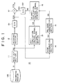
FIG. 1 and FIG. 2 are drawings for describing an
image output device (referred to simply as output device
hereinafter) 10 and an image recording device (referred to
simply as recording device hereinafter) 20 used in an image
anti-duplication control system according to this embodiment.
In other words, the output device 10 corresponds to the
output system of a DVD device, and the recording device 20
corresponds to the recording system of a DVD device.
In FIG. 1, on a recording medium 100, digitized
images and audio signals are recorded together with an
anti-duplication control signal as additional information.
The recording medium 100 is a DVD in this embodiment. The
anti-duplication control signal may be recorded on the
innermost or outermost TOC or a track area known as the
directory, or it may be inserted on a track in which image
data or audio data is recorded, namely, on the area different
from the data recording area. An example described
hereinafter is of the latter case, namely that the case the
anti-duplication control signal is read out at the same time
as the video signal is read out.
In this embodiment, the anti-duplication control
signal may be a signal for limiting the number of
duplications such as a signal for permitting only the first
duplication, To simplify the description in this embodiment,
the anti-duplication control signal is a 1 bit signal for
indicating inhibition or permission of a video signal
duplication. For description, the anti-duplication control
signal is described as a signal added in the video signal.
As shown in FIG. 1, the playback device 10 of in
this embodiment comprises a read-out section 11, decoding
section 12, anti-duplication control signal extracting
section 13, sync separation section 14, PN code generation
section 15, spectrally spread anti-duplication control signal
generation section 16 (referred to as SS (SS is an
abbreviation of spectral spreading) anti-duplication control
signal generator hereinafter), addition section 17, and D/ A
conversion circuits 191, and 192.
The read-out unit 11 extracts a playback video
signal component S2 from the signal S1 obtained by playing
back the recording medium 100, and supplies it to the
decoding section 12 and anti-duplication control signal
extraction section 13.
The decoding section 12 demodulates the playback
video signal component S2, generates a digital video signal,
and supplies it to the D/A conversion circuit 191. The D/A
conversion circuit 191 performs D/A conversion of the digital
video signal to generate an analog video signal S2A
comprising a sync signal, and supplies the result to the sync
separator 14 and addition section 17.
The anti-duplication control signal extraction
section 13 extracts an anti-duplication control signal S3
added to the playback video signal component S2, and the
extracted anti-duplication control signal S3 is supplied to
the SS anti-duplication control signal generation section 16.
The sync separation section 14 removes an video
sync signal S4 from the analog video signal S2A, and supplies
the result to the PN code generation section 15. According
to this embodiment, a horizontal sync signal is used as the
video sync signal S4.
The PN code generator 15 generates a PN code
(spread code) using the vertical sync signal S4 as a
reference and forms various timing signals to be used in
other processors. In detail, the PN code generation section
15 functions as a spread code generation means for generating
a spread code for spectral spreading.
FIG. 3 is a block diagram for describing the PN
code generation section 15 of the output device 10 used in
this embodiment. Figs. 4A to 4D are diagrams for describing
a PN code string S5 generated in the PN code generating
section 15.
As shown in FIG. 3, the PN code generation section
15 comprises a PN code generation control section 151, PLL
circuit 152, PN code generator 153, and timing signal
generation section 154. The horizontal sync signal S4
extracted in the sync separator 14 is supplied to the PN code
generator 151 of the PN code generation section 15, the PLL
circuit 152, and the timing signal generation section 154.
The PN code generation control section 151
generates an PN code start timing signal T1 (Fig. 4B) which
indicates a timing for starting generation of a PN code
string in synchronizing with the vertical sync signal S4
(Fig. 4A). In this embodiment, the PN code start timing
signal T1 is generated with reference to the frond edge of
the vertical sync signal S4, and indicates the timing so as
that generation of a PN code string which repeats every one
vertical interval is started.
The PN code generation control section 151
generates a PN code generation control signal VT (Fig. 4C)
for indicating vertical intervals where PN code strings are
to be generated and vertical intervals where PN code strings
are not to be generated. The PN code generation control
signal VT is a signal for controlling a switch circuit SW1
which will be described hereinafter.
In this embodiment, the PN code generation control
signal VT is a signal having a low level interval or high
level interval which are alternating every one vertical
interval with reference to the front edge of the vertical
sync signal S4 as shown in Fig. 4C.
The PN code start timing signal T1 generated in the
PN code generation control section 151 is supplied to the PN
code generator 153, and the PN code generation control signal
VT is supplied to the switch circuit SW1.
The PLL circuit 152 generates a clock signal CLK
based on the horizontal sync signal S4 supplied to it, and
the clock signal is supplied to the PN code generator 153.
The PLL circuit 152 in this embodiment generates a clock
signal CLK having a frequency of, for example, 1 MHz as
described hereinafter.
The PN code generator 153 determines PN code string
generation start timing based on the PN code start timing
signal T1, and also generates a PN code corresponding to the
clock signal CLK, and supplied it to the input terminal of
the switch circuit SW1.
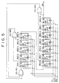
Fig. 5 is a diagram for illustrating one example of
the PN code generator 153. The PN code generator shown in
Fig. 5 comprises 12 D-flip-flops REG1 to REG12 and three
exclusive-OR circuits EX-OR1 to EX-OR3. As shown in Fig. 5,
upon receiving supply of a PN code start timing signal T1
used as a reset signal, clock signal CLK, and enable signal
EN, the PN code generator 153 in this example generates a PN
code having 4095 chips per one vertical interval.
In this case as described hereinbefore, the clock
rate of 250 kHz gives one period of a PN code string of
4095/250=16.38 ms, and a PN code having 4095 chips is
generated in an approximate one vertical interval (16.7 ms).
By using the PN code start timing signal T1 as a reset
signal, a PN code string having a pre-determined code pattern
is generated from its head every one vertical interval. In
other words, a PN code string which repeats every one
vertical interval is generated.
In this embodiment, the PN code generator 153
generates M series codes which generate codes [1] and [0]
randomly without deviation, and converts a generated code
level [0] to [-1] to generates a PN code string composed of
codes [1] and [-1].
The switch circuit SW1 is provided with two input
terminals-a and -b as shown in Fig. 3. To the input
terminal-a, the PN code string generated by the PN code
generator 153 as described herein above is supplied, on the
other hand, 0 level signal that is the median value of the PN
code string composed of 1 and -1 is supplied to the other
input terminal-b.
The switch SW1 is controlled correspondingly to the
PN code generation control signal VT outputted from the PN
code generation control section 151, switched to the input
terminal-a side correspondingly to the trailing edge of a PN
code generation control signal VT, and switched to the input
terminal-b side correspondingly to the leading edge of a PN
code generation control signal VT.
From the switch circuit SW1 as shown in Fig. 4D,
the PN code string is thereby outputted every one vertical
interval, and 0 level signals are outputted in vertical
intervals on which a PN code string is not outputted, as the
result, the PN code string S5 is generated.
In detail, the switch SW1 outputs a PN code string
outputted from the PN code generator 153 in low level
intervals of the PN code generation control signal VT and
outputs a O level signal in high level intervals of the PN
code generation control signal VT, thereby the PN code string
is generated intermittently every second vertical interval
with respect to the video signal. The PN code string S5
outputted from the switch circuit SW1 is supplied to the SS
anti-duplication control signal generation section 16.
The timing signal generation section 154 generates
various timing signals based on the vertical sync signal S4
and output it.
The SS anti-duplication control signal generation
section 16 generates a spectrally spread anti-duplication
control signal S6 by spectrally spreading the
anti-duplication control signal using the PN code string S5,
and supplies it to the D/A conversion circuit 192. The D/A
conversion circuit 192 converts the spectrally spread signal
S6 to an analog spectrally spread signal S6A and supplies it
to the addition section 17.
The addition section 17 superimposes the analog
spectrally spread signal S6A on the analog video signal S2A
to generate an output video signal S7A, and outputs it. As
described herein above, the addition section 17 functions as
a superimposition means for superimposing a spectral spread
signal S6A that is the spectrally spread anti-duplication
control signal using the PN code string S5.
The analog output video signal S7A on which the
spectrally spread anti-duplication control signal is
superimposed is supplied to a monitor receiver for displaying
a video image or a recording device 20 which will be
described hereinafter.
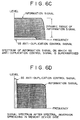
Figs. 6A to 6D show a relation between the
anti-duplication control signal and main information signal,
video signal in this example, in the form of spectrum. The
anti-duplication control signal contains not so much
information, and is a low bit rate signal having a narrow
band as shown in Fig. 6A. The anti-duplication control
signal is changed by performing spectral spreading to a
signal having a wide band as shown in Fig. 6B. When, the
spectral spread signal level becomes low in inverse
proportion to the enlargement ratio of the band.
When the spectral spread signal or SS
anti-duplication control signal S6A is superimposed on an
information signal in the addition section 17, the SS
anti-duplication control signal S6A is superimposed with a
level smaller than that of the dynamic range of the video
signal that is an information signal as shown in Fig. 6C.
Such superimposition can prevents the main information signal
from being deteriorated. Hence, when the video signal on
which the SS anti-duplication control signal is superimposed
is supplied to a monitor receiver to playback an image, the
SS anti-duplication control signal does not affect adversely
and a good playback image is obtained.
On the other hand, when inversion spectral spread
is performed to detect the SS anti-duplication control signal
in the recording side as described hereinafter, the SS
anti-duplication control signal is restored again as a signal
having a narrow band as shown in Fig. 6D. By giving a
sufficient band enlargement ratio, the power of the
anti-duplication control signal after inversion spreading
exceeds that of the information signal, and it becomes
possible to detect the anti-duplication control signal.
In this case, it is impossible to remove or alter
the anti-duplication control signal by way of simple
replacement of a frequency filter or information, because
the SS anti-duplication control signal is superimposed on the
analog video signal superimposed in the same time and same
frequency as those of the analog video signal.
Therefore, the SS anti-duplication control signal
superimposed on a video signal will not be removed, and the
SS anti-duplication control signal is provided consistently
to a device such as monitor receiver or recording device.
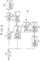
Next, the recording device 20 which receives supply
of the video signal S7A from the above-mentioned output
device 10 and records the video signal is described. The
recording device 20 of this embodiment is provided with a
coding section 21, sync separation section 22, PN code
generation section 23, PN code inversion section 24,
detection section 25 for detecting the spectrally spread
anti-duplication control signal superimposed on the video
signal (referred to as SS anti-duplication control signal
detection section hereinafter), duplication control section
26 for controlling duplication control such as permission or
inhibition, write section 27, and A/D conversion circuit 291
as shown in Fig. 2. The recording medium 200 is a DVD on
which the video signal is written by the recording medium 20.
The video signal S7A supplied from the output
device 10 is converted to a digital video signal S8 by the
A/D conversion circuit 291 and the resultant signal is
supplied to the coding section 21, sync separation section
22, and SS anti-duplication control signal detection section
25.
The coding section 21 receives supply of the
digital video signal S8, and performs coding processing such
as removal of the video sync signal and data compression of
the digital video signal to generates a digital video signal
S9 for supplying and recording on the recording medium 200,
and the digital video signal S9 is supplied to the write
section 27.
The sync separation section 22 extracts the video
sync signal S11 from the digital video signal S8 before
coding processing, and supplies it to the PN code generation
section 23. In the recording device 20 of this embodiment, a
vertical sync signal is used as the video sync signal S11
corresponding to the above-mentioned output device 10.
The PN code generation section 23 generates a PN
code as the spread code based on the vertical sync signal
S11, and generates various timing signals used by other
processing sections.
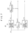
Fig. 7 is a block diagram for illustrating the PN
code generation section 23 of the recording device 20 of this
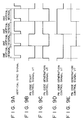
embodiment, and Fig. 8A to 8D are diagrams for describing the
PN code start timing signal T2, PN code inversion control
signal VT2, and PN inversion code S12 generated by the PN
code generation section 23.
As shown in Fig. 7, the PN code generation section
23 is provided with a PN code generation control section 231,
PLL circuit 232, PN code generator 233, and timing signal
generation section 234. Though the PN code generation
section 23 is a section for generating the PN code string and
various timing signal like the PN code generation section 15
of the above-mentioned output device 10 shown in Fig. 3, this
section 23 is different from the PN code generation section
15 of the output device 10 in that the switch circuit SW1 is
not provided.
The PN code generation control section 231
generates a PN code start timing signal T2 (Fig. 8B) which
indicates timing for starting generation of a PN code string
based on the vertical sync signal S11 (Fig. 8A). In this
embodiment, the PN code start timing signal T2 is generated
with reference to the front edge of the vertical sync signal
S11. The PN code start timing signal T2 indicates PN code
string generation start timing which repeats every one
vertical interval.
The PLL circuit 232 generates a clock signal CLK 2
with reference to the vertical sync signal S11 supplied to
the PLL circuit 232, and supplies it to the PN code generator
233. The PLL circuit 232 of this embodiment generates a
clock signal CLK 2 of, for example, frequency of 250 kHz like
the PLL circuit 152 of the PN code generation section 15 of
the above-mentioned output device 10.
The PN code generator 233 determines PN code
generation start timing based on the PN code start timing
signal T2, and generates a PN code corresponding to the clock
signal CLK 2 and outputs it. Further, the PN code generator
233 has the same structure as that of the above-mentioned PN
code generator 153 shown in Fig. 5.
The PN code generator 233 generates a PN code S12
using the PN code start timing signal T2 and clock signal CLK
2. Thereby, generation of the PN code string S12 is started
at the same start timing as that of the PN code string S5
with respect to the video signal supplied to the recording
device 20 which PN code string S5 is generated in the output
device 10.
In this embodiment, the PN code string S12 is a
string that is the PN code string of one period generated
from the head every one vertical interval like the PN code
string used for spectrally spreading the anti-duplication
control signal in the above-mentioned output device 10.
The timing signal generation section 234 of the PN
code generation section 23 generates a PN code inversion
control signal
VT2 (Fig. 8C) used in the PN code inversion section 24 and
output it. In this embodiment, the PN code inversion control
signal VT2 is a signal for inverting every one vertical
interval.
As described herein above, the PN code string S12
and PN code inversion control signal VT2 generated in the PN
code generation control section 23 are supplied to the PN
code inversion section 24.
The PN code inversion section 24 inverts the
polarity of the PN code string S12 supplied from the PN code
generation section 23 every one vertical interval based on
the PN code inversion control signal VT2 to generates a PN
inversion code S13 (Fig. 8D).
In detail, the PN code inversion section 24 outputs
the supplied PN code string S12 as it is in the low level
interval of the PN code inversion control signal VT2, and on
the other hand, in the high level interval of the PN code
inversion control signal VT2, the PN code inversion section
24 inverts the polarity of the supplied PN code string S12.
As the result as shown in Fig. 8D, a PN inversion code S13
having the different polarity alternating every one vertical
interval is generated.
Herein, the polarity inversion means inversion from
a PN code of 1 to a PN code of -1 and inversion from a PN
code of -1 to a PN code of 1, and in this embodiment, the PN
inversion code S13 is generated by outputting all the PN code
strings in one vertical interval or by inverting the polarity
of all the PN code string in one vertical interval by the PN
code inversion section 24. The generated PN inversion code
13 is supplied to the SS anti-duplication control signal
detection section 25 as an inversion spreading PN code string
S13 used for inversion spectral spreading.
The SS anti-duplication control signal detection
section 25 functions as an inversion spectral spreading
processing means, and the function allows the SS
anti-duplication control signal detection section 25 to
extract the spectrally spread anti-duplication control signal
superimposed on the video signal S8 by performing inversion
spectral spreading using the PN inversion code S13 as a
reference signal, and the SS anti-duplication control signal
detection section 25 supplies it to the duplication control
section 26 as the anti-duplication control signal S14.
When inversion spectral spreading is performed in
the SS anti-duplication control signal detection section, as
described hereinbefore, the video signal S8 containing the
spectrally spread anti-duplication control signal is
multiplied by the PN inversion code S13, and the result is
integrated to extract the anti-duplication control signal
superimposed on the video signal S8. While inversion
spectral spreading, the polarity of the video signal S8 is
inverted every one vertical interval by multiplying the PN
inversion code S13.
The video signal is a correlative signal between
adjacent fields. Therefore, the video signal component
having different polarity repeating every one vertical
interval is cancelled and offset by integration during
inverse spectral spreading. Thus, the anti-duplication
control signal superimposed on the video signal is
effectively extracted without adverse effect of high level
video signals.
The anti-duplication control signal S14 extracted
by the SS anti-duplication control signal detection section
25 as described herein above is supplied to the duplication
control section 26.
The duplication control section 26 decodes the
anti-duplication control signal S14 and judges whether the
video signal S7A supplied to the recording device 20 is a
duplication permit signal or a duplication inhibition signal.
Based on the judgement result, the duplication control
section 26 generates a write control signal S15 and supplies
it to the write section 27 to perform duplication control of
the video signal S9, thus the selection whether writing is
permitted or not permitted is performed.
The write section 27 writes the video signal S9 on
the recording medium 200 if the write control signal S15 is a
signal for permitting writing, on the other hand, the write
section 27 does not write the video signal S9 on the
recording medium 200 if the write control signal S15 is a
signal for inhibiting writing.
As described herein above, in the video signal
duplication control system comprising the output device 10
and recording device 20 of this embodiment, by starting
generation of the PN code string every one vertical interval
based on the vertical sync signal, generation of the PN code
string is started at the same timing as that of the video
sync signal in both the output device 10 and recording device
20.
Further, in the output device 10, the
anti-duplication control signal is spectrally spread using
the PN code string S5 generated every one vertical interval
with respect to the video signal, and the resultant signal is
superimposed on the video signal. In other words, the
spectrally spread anti-duplication control signal is
superimposed and outputted every second vertical interval of
the video signal.
In the recording device 20, correspondingly to the
video signal outputted from the output device 10, the PN
inversion code S13 having the same PN code string S12 as the
PN code string S5 used in spectral spreading is generated for
the vertical interval on which the spectral spread signal S6A
is superimposed, on the other hand, the PN inversion code S13
having the PN code string having opposite polarity to that of
the PN code string S12 is generated for the vertical interval
on which the spectral spread signal S6A is not superimposed,
and inversion spectral spreading is performed using this PN
inversion code.
Therefore, the same PN code string as the PN code
string used for spectral spreading is multiplied for the
vertical interval on which the spectral spread code is
superimposed in inversion spectral spreading, on the other
hand, the PN code string having opposite polarity to that of
the same PN code string as used for spectral spreading is
multiplied for the vertical interval on which the spectral
spread signal is not superimposed, and the result is
integrated.
In this case, the video signal component of
adjacent vertical intervals is cancelled by integration
during inversion spectral spreading, hence, only the
anti-duplication control signal superimposed on the video
signal as a spectral spread signal is extracted. The
anti-duplication control signal superimposed on the video
signal is extracted without adverse effect of high level
video signals.
Inversion spectral spreading is thereby performed
rapidly and correctly, and thus detection efficiency of the
spectrally spread anti-duplication control signal
superimposed on the video signal is improved and spread gain
of the anti-duplication control signal is reduced.
As described hereinbefore, in the output device 10
of this embodiment, the PN code string is generated every
second vertical interval with reference to the front edge of
the vertical sync signal (Fig. 9A) by using the PN code
generation control signal VT which is inverted every vertical
interval as shown in Fig. 9B, and by spectrally spreading the
anti-duplication control signal using this PN code string,
the anti-duplication control signal which is spectrally
spread every second vertical interval is superimposed on the
video signal, however, the present invention is by no means
limited to the above-mentioned case.
For example, as shown in Fig. 9C, a signal having
the phase opposite to that of the PN code generation control
signal VT shown in Fig. 9B may be used. In this case, the
spectrally spread anti-duplication control signal may be
superimposed on either odd field or even field of the video
signal.
Alternatively, as shown in Figs. 9D and 9E, by
generating the PN code string every two vertical interval
(one frame), the spectrally spread anti-duplication control
signal may be superimposed on the video signal every two
vertical interval (one frame).
The present invention is by no means limited to the
case that the PN code string used for spectral spreading is
generated every second vertical interval or every third
vertical interval, however, the PN code string may be
generated every integral multiple of one vertical interval
such as every fourth vertical interval or every fifth
vertical interval.
In general, the video signal interval on which the
anti-duplication control signal is superimposed and the video
signal interval on which the anti-duplication control signal
is not superimposed may be prescribed so that the video
signal of both video signal intervals is sufficiently
correlative to cancel the video signal of both video signal
intervals by calculating the difference between the video
signal in the video signal interval on which the spectrally
spread anti-duplication control signal is superimposed and
the video signal in the adjacent video signal interval on
which the spectrally spread anti-duplication control signal
is not superimposed.
Further, in the recording device 20 correspondingly
to the output device 10, the same PN code string as the PN
code used for spectrally spreading the anti-duplication
control signal in the output device is generated in the video
signal interval on which the spectrally spread
anti-duplication control signal is superimposed, on the other
hand, the PN code string having the opposite polarity to that
of the PN code string used for spectral spreading is
generated in the video signal interval on which the
spectrally spread anti-duplication control signal is not
superimposed which video signal interval is adjacent to the
video signal interval on which the spectrally spread
anti-duplication control signal is superimposed.
In the above-mentioned embodiment, in the output
device 10 and recording device 20, the PN code string is
generated at the timing synchronous with the vertical sync
signal using the vertical sync signal as the reference
signal, however, the reference signal is by no means limited
to the vertical sync signal, and the horizontal sync signal
may be used as the reference signal.
In the case that the horizontal sync signal is used
as described herein above, in the output device 10, the PN
code string used for spectral spreading may be generated
every integral multiple of one horizontal interval such as
every second horizontal interval, every third horizontal
interval, or every fourth horizontal interval.
Further in this case, in the recording device 20,
the PN code string is generated every integral multiple of
one horizontal interval such as every second horizontal
interval, every third horizontal interval, or every fourth
horizontal interval correspondingly to the output device 10,
and the polarity of the generated PN code string is inverted
in the interval on which the anti-duplication control signal
is not superimposed.
Further, in the above-mentioned embodiment, the PN
code string which repeats every vertical interval is
generated every second vertical interval, and the
anti-duplication control signal is spectrally spread using
this PN code string, and the spectrally spread
anti-duplication control signal is superimposed every second
vertical interval on the video signal. However, the present
invention is by no means limited to the case.
For example, the PN code string is generated every
one vertical interval, the anti-duplication control signal is
spectrally spread every second horizontal interval using this
PN code string, and the anti-duplication control signal may
be superimposed every second horizontal interval on the video
signal.
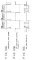
For example, Fig. 10A to 10C are diagrams for
describing an example of a case that the anti-duplication
control signal is spectrally spread using the PN code string
which repeats every one vertical interval, and the spectrally
spread anti-duplication control signal is superimposed every
second horizontal interval.
In detail, in the PN code generation section 15 of
the output device 10, the PN code string used for spectral
spreading is generated, for example, every one vertical
interval. The PN code generation control signal HT (Fig.
10B) which is inverted every one horizontal interval is
generated based on the horizontal sync signal (Fig. 10A).
Based on the PN code generation control signal HT, the switch
circuit SW1 of the PN code generation section 15 described
using Fig. 3 is controlled to output the PN code from the PN
code generator 153 every second horizontal interval and is
controlled to output 0 level signal in the horizontal
interval where the PN code is not outputted.
As the result, the PN code string is generated
every second horizontal interval as shown in Fig. 10C. The
anti-duplication control signal is spectrally spread using
the PN code string shown in Fig. 10A to 10C, and the
spectrally spread anti-duplication control signal is
superimposed every one horizontal interval of the video
signal.
Fig. 11A to 11C are diagrams for describing the
processing in the recording device 20 in this case. In
detail, in the recording device 20 like the output device 10,
the PN code string which repeats every one vertical interval
is generated, and also the PN code inversion control signal
HT2 which is inverted every one horizontal interval is
generated based on the horizontal sync signal (Fig. 11A) as
shown in Fig. 11A to 11C.
Based on the PN code inversion control signal HT2,
the PN code string having the polarity opposite to the PN
code string generated in the horizontal interval on which the
spectrally spread anti-duplication control signal is
superimposed is generated as shown in Fig. 11C.
In the case that inversion spectral spreading is
performed using the PN code string which is inverted every
one horizontal interval as described herein above, by
integration during inversion spectral spreading, the video
signal component is cancelled due to correlation between
horizontal scanning lines as in the case of the
above-mentioned embodiment, and the anti-duplication control
signal superimposed every second horizontal interval is
detected efficiently.
Further, the start timing of PN code string
generation is not limited to the case of every one vertical
interval, may be every plurality of vertical intervals or
every horizontal intervals. In sum, the PN code is generated
at the same timing as that of the video signal in the output
device 10 and recording device 20.
Further, the video signal interval on which the
spectrally spread anti-duplication control signal is
superimposed is by no means limited to the case of every
second horizontal interval, for example, the anti-duplication
control signal may be superimposed every second pixel on the
video signal.
Further, in the output device 10 of the
above-mentioned embodiment, the spectrally spread
anti-duplication control signal is superimposed over one
vertical interval or one horizontal interval as shown in
Figs. 4A to 4D and Fig. 10A to 10C, however, the present
invention is by no means limited to the case.
For example, one vertical interval is divided into
a plurality of sub-intervals, the anti-duplication control
signal spectrally spread on one divided sub-interval or on a
plurality of divided sub-intervals may be superimposed.
Fig. 12A to 12D are diagrams for describing an
example of the case that one vertical interval is divided
into two sub-intervals and the spectrally spread
anti-duplication control signal is superimposed on one
sub-interval in the above-mentioned output device 10.
In this case, the output device 10 generates the PN
code start timing signal T1 for generating the PN code
string, for example, every one vertical interval with
reference to the front edge of the vertical sync signal (Fig.
12A), and also generates the PN code generation control
signal VT for generating the PN code string during 1/2
vertical interval every second vertical interval as shown in
Fig. 12C.
As the result in the output device 10, the PN code
string S5 is generated so that the PN code string is
generated during 1/2 vertical interval every second vertical
interval as shown in Fig. 12D, and the level is 0 in other
intervals. The anti-duplication control signal is spectrally
spread using this PN code string S5 (Fig. 12D), the
spectrally spread anti-duplication control signal is
superimposed on 1/2 vertical interval repeating every second
vertical interval.
Fig. 13A to 13D are diagrams for describing the
processing in the recording device 20 which receives supply
of the anti-duplication control signal spectrally spread
during 1/2 vertical interval repeating every second vertical
interval.
The recording device 20 generates the PN code start
timing signal T2 for generating the PN code string every one
vertical interval based on the front edge of the vertical
sync signal (Fig. 13A) like the output device 10. In
addition, the recording device 20 generates the PN code
inversion control signal VT2 for inverting the polarity of
the generated PN code string every one vertical interval.
As the result, in the recording device 20, the PN
code string having the same code pattern as that of the
output device 10 is generated based on the PN code timing
signal T2. In the case of this example, when the PN code
string corresponding to 1/2 vertical interval, generation of
the PN code stops, generation of the PN code string re-starts
correspondingly to rising of the next PN code start timing
signal, and by repeating stop and re-start, the PN code
string corresponding to 1/2 vertical interval is generated
every one vertical interval.
The recording device 20 inverts every one vertical
interval the polarity of the PN code string generated every
one vertical interval based on the PN code inversion control
signal VT2. The PN inversion code S13 having the polarity
inverted every one vertical interval is thereby generated.
By performing inversion spectral spreading using
this PN inversion code S13 and by integration during
inversion spectral spreading, the video signal component of
1/2 vertical interval of the field on which the
anti-duplication control signal is superimposed and the video
signal component of adjacent 1/2 vertical interval of the
field on which the anti-duplication control signal is not
superimposed are cancelled each other.
Accordingly, also in this case, the
anti-duplication control signal superimposed on the video
signal is extracted efficiently because the video signal
component is cancelled between highly correlative fields.
As described herein above, the spectrally spread
anti-duplication control signal is superimposed on the video
signal interval, in this case, the predetermined interval in
the field such as 1/2 vertical interval or 1/3 vertical
interval. The anti-duplication control signal is not
superimposed on the interval corresponding to the video
signal interval which is highly correlative to this video
signal interval (field), and outputted.
In the recording device side, the same PN code
string as the PN code string used for spectral spreading is
generated for the interval on which the spectrally spread
anti-duplication control signal is superimposed, on the other
hand, the PN code string having the polarity opposite to that
of the PN code string used for spectral spreading is
generated for the interval corresponding to the video signal
interval on which the anti-duplication control signal having
a correlation to the video signal interval is not
superimposed, and inversion spectral spreading may be
performed using the inversion spreading PN code having the
inverted polarity.
Alternatively, one horizontal interval is divided
into a plurality of sub-intervals, and the spectrally spread
anti-duplication control signal may be superimposed on one
divided sub-interval or a plurality of divided sub-intervals
out of divided sub-intervals. Also in this case, the
spectrally spread anti-duplication control signal is
superimposed on the predetermined interval in the one
horizontal interval (one line), and the anti-duplication
control signal is not superimposed on the interval
corresponding to the line correlative to the predetermined
interval, in the output device like the case of the
above-mentioned one vertical interval (one field).
In the recording device, the inversion spreading PN
code having different polarity may be used as described
herein above dependently on the type of the interval whether
on which the anti-duplication control signal is superimposed
or on which the anti-duplication control signal is not
superimposed in the correlative horizontal interval.
[Second Embodiment]
Next, the second embodiment of the video signal
duplication control system comprising a video signal output
device and video signal recording device in accordance with
the present invention will be described herein after.
In the second embodiment, by removing the video
signal component before inversion spectral spreading is
performed in the recording device, only the spectrally spread
anti-duplication control signal component superimposed on the
video signal is extracted, the resultant signal is subjected
to inversion spectral spreading, thereby, the
anti-duplication control signal superimposed on the video
signal is extracted rapidly and correctly.
In the second embodiment, the same output device as
the output device 10 used in the first embodiment described
using Fig. 1 is used. Therefore, the output device 10 in the
second embodiment spectrally spreads the anti-duplication
control signal read out from the recording medium 100 using
the PN code string generated every second vertical interval,
and superimposes the spectrally spread anti-duplication
control signal on the video signal played back from the
recording medium 100 every second vertical interval, and
outputs it.
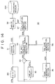
Fig. 14 is a block diagram for illustrating a
recording device 30 used in the second embodiment. The
recording device 30 receives a video signal outputted from
the output device 10 used in this embodiment and records the
video signal on the recording medium 200.
The recording medium 30 of the second embodiment is
provided with a coding section 31, delay circuit 32,
subtraction section 33, SS anti-duplication control signal
detection section 34, sync separation section 35, PN code
generation section 36, duplication control section 37, write
section 38, and A/D conversion circuit 391 as shown in Fig.
14.
The video signal S7A supplied from the output
device 10 is subjected to A/D conversion through the A/D
conversion circuit 391 and the digital video signal S31 is
supplied to the coding section 31, delay circuit 32,
subtraction section 33, and sync separation section 35.
The coding section 31 receives the digital video
signal S31, and then removes the sync signal and performs
coding processing such as data compression of the digital
video signal to generate a recording digital video signal
S32, and supplies it to the write section 38.
In the second embodiment, the delay circuit 32
delays the supplied digital video signal S31 by one vertical
interval and supplies it to the subtraction section 33. The
subtraction section 33 subtracts the digital video signal S31
from the one vertical interval-delayed digital video signal
S31L from the delay circuit 32 to output the spectrally
spread anti-duplication control signal superimposed on the
digital video signal.
In detail, on the video signal supplied from the
output device 10, the anti-duplication control signal
spectrally spread using the PN code string generated every
second vertical interval as shown in Fig. 4D is superimposed
every second vertical interval. Hence, in this embodiment,
first the video signal in the vertical interval on which the
anti-duplication control signal spectrally spread by delaying
the video signal S31 by one vertical interval by means of the
delay circuit 32 is superimposed is supplied to the
subtraction section 33 through the delay circuit 32.
When, to the subtraction section 33, the video
signal in the vertical interval on which the spectrally
spread anti-duplication control signal is not superimposed
subsequent to the vertical interval on which the spectrally
spread anti-duplication control signal is superimposed is
supplied from the A/D conversion circuit 391.
As described hereinbefore, the video signal is
highly correlative between adjacent fields. Therefore, by
subtracting the video signal in the vertical interval on
which the anti-duplication control signal is not superimposed
from the video signal in the preceding vertical interval on
which the spectrally spread anti-duplication control signal
is superimposed, the video signal component is offset, and
the spectrally spread anti-duplication control signal
component S33 is supplied to the SS anti-duplication control
signal detection section 34.
However, in the case that the video signal delayed
by one vertical interval by means of the delay circuit 32 is
subtracted from the video signal in the subsequent vertical
interval successively, the video signal on which the
spectrally spread anti-duplication control signal is
superimposed is inevitably subtracted from the video signal
on which the spectrally spread anti-duplication control
signal is not superimposed. In this case, such subtraction
is not preferable because the spectrally spread
anti-duplication control signal component having the inverted
polarity is inevitably calculated.
To cope with this problem, the delay circuit 32 of
the second embodiment delays only the video signal in the
vertical interval on which the spectrally spread
anti-duplication control signal is superimposed by one
vertical interval. In the subtraction section 33, the video
signal component in the vertical interval on which the
anti-duplication control signal is superimposed is offset by
the video signal component in the subsequent vertical
interval on which the anti-duplication control signal is not
superimposed, and the video signal component is removed, then
the spectrally spread anti-duplication control signal
component is outputted.
On the other hand, receiving supply of the A/D
converted video signal S31, the sync separation section 35
extracts the vertical sync signal S34 contained in the video
signal S31 and supplies it to the PN code generation section
33.
The PN code generation section 33 has the same
structure as the PN code generation section 23 of the
recording device 20 described hereinbefore. The PN code
generation section 33 of the second embodiment generates the
same PN code string S35 as the PN code string used for
spectral spreading in the output device 10 corresponding to
the clock signal generated based on the vertical sync signal
S34 every one vertical interval with reference to the
vertical sync signal S34. The PN code string S35 is supplied
to the SS anti-duplication control signal detection section
34 as an inversion spreading PN code string.
By performing inversion spectral spreading on the
spectrally spread anti-duplication control signal component
S33 supplied from the subtraction section 33 using the
inversion spreading PN code string S35, the SS
anti-duplication control signal detection section 34 extracts
the anti-duplication control signal S36 and supplies it to
the duplication control section 37.
The duplication control section 37 generates the
control signal S37 for controlling writing of the video
signal S32 on the recording medium 200 depending on the
anti-duplication control signal S36 like the duplication
control section 26 of the recording device 20 described
hereinbefore, and supplies it to the write section 38.
The write section 38 writes the video signal S32 on
the recording medium 200 if the control signal S37 generated
depending on the anti-duplication control signal S36 is a
signal for indicating permission of writing, on the other
hand, the write section 38 does not write the video signal
S32 on the recording medium 200 if the control signal S37 is
a signal for indicating inhibition of writing.
As described herein above, in the recording device
30 of the second embodiment, the anti-duplication control
signal superimposed on the video signal can be extracted
without adverse effect of high level video signal components
like the above-mentioned first embodiment, because the video
signal component in adjacent vertical intervals which are
highly correlative is removed. Thereby, inversion spectral
spreading is performed correctly and rapidly, the detection
efficiency of the spectrally spread anti-duplication control
signal superimposed on the video signal is improved, and the
spread gain of the anti-duplication control signal is
reduced.
The output device 10 of the second embodiment may
generate the PN code string used for spectral spreading every
integral multiple of vertical interval such as every second
vertical interval, every third vertical interval, or every
fourth vertical interval.
In this case, in the recording device 30, the video
signal to be supplied to the subtraction section 34 may be
delayed by means of the delay circuit 33 by the video signal
interval on which the video signal is superimposed
correspondingly to the output device 10. Further, in this
case, only the video signal in the video signal interval on
which the anti-duplication control signal is superimposed may
be delayed.
Further, in the output device 10 and recording
device 30 of the second embodiment, the horizontal sync
signal may be used as the reference signal instead of the
vertical sync signal as in the output device 10 and recording
device 20 in the first embodiment described hereinbefore.
In the case that the horizontal sync signal is used
as described herein above, in the output device 10, the PN
code string used for spectral spreading may be generated
every integral multiple of horizontal interval as in the case
that the vertical sync signal is used.
Further, in the recording device 30, corresponding
to the output device 10 used in the second embodiment, the
video signal on which the anti-duplication control signal is
superimposed may be delayed by integral multiple of one
horizontal interval.
For example, one vertical interval is divided into
a plurality of sub-intervals, and the spectrally spread
anti-duplication control signal may be superimposed on one
divided sub-interval or a plurality of divided sub-intervals
out of the divided sub-intervals as in the first embodiment
described hereinbefore.
For example, the spectrally spread anti-duplication
control signal may be superimposed on the video signal
interval, in this case the predetermined interval, such as
1/2 vertical interval or 1/3 vertical interval. In this
case, the anti-duplication control signal is not superimposed
on the interval corresponding to the video signal interval
highly correlative to this video signal interval (field) for
outputting.
In the recording device side, the difference
between the interval on which the spectrally spread
anti-duplication control signal is superimposed and the
interval correlative to this video signal interval on which
the anti-duplication control signal is not superimposed is
calculated. In other words, in the recording device 20 of
the second embodiment, delay is adjusted so that the
difference between the video signal in the interval on which
the anti-duplication control signal is superimposed and the
interval which is correlative to that interval can be
calculated.
Of course, one horizontal interval is divided into
a plurality of sub-intervals, the spectrally spread
anti-duplication control signal may be superimposed on one
divided sub-interval or a plurality of divided sub-intervals
out of the divided sub-intervals.
As described herein above, in the case that the
video signal interval on which the spectrally spread
anti-duplication control signal is to be superimposed is so
long as to be equal to a plurality of vertical intervals, or
to the contrary, the video signal interval is so short as to
be equal to 1/4 vertical interval or 1/8 vertical interval,
the PN code generator suitable for such video signal may be
used.
Further, in the case that the PN code generator
which generates a long PN code string having one period of,
for example, four vertical intervals, the PN code string
suitable for the video signal interval on which the
anti-duplication control signal is to be superimposed is may
be generated by stopping temporarily the PN code generator
using the enable signal supplied to the PN code generator.
Further, for example, two PN code generators for
generating the PN code string having one period of one
vertical interval are provided, and used with switching,
thereby, for example, the video signal interval on which the
anti-duplication control signal is to be superimposed longer
than one vertical interval can be processed properly.
Further, in the case that the PN code generator for
generating a long PN code string is used, or two PN code
generators are provided as described herein above, the PN
code string having the same code pattern as the PN code
string used for spectral spreading corresponding to the
interval on which the spectrally spread anti-duplication
control signal is superimposed is generated also in the
recording device side by using the video signal sync signal
as the reference.
In the above-mentioned embodiment, the PN code
start timing signal T1 is generated with reference to the
front edge of the video sync signal, however, by no mean
limited to the case, the phase relation between respective
signals may be deviated arbitrarily, for example, the
position delayed by several clocks from the front edge of the
video sync signal may be applied as the reference.
Further, in the above-mentioned embodiment, the
case of the analog connection in which an analog video signal
is supplied from the output device to the recording device is
described for description, however, the present invention may
be applied to the case of digital connection.
In other words, the spectrally spread
anti-duplication control signal can be superimposed either on
the analog video signal and on the digital video signal.
Further, in the recording device 20 and recording
device 30, the video signal to be supplied to the SS
anti-duplication control signal detection section is
subjected to filtration previously, and only the low level
video signal on which the spectrally spread anti-duplication
control signal is superimposed is extracted, and then the
extracted video signal may be supplied to the SS
anti-duplication control signal detection section.
In the above-mentioned embodiment, the case that
the output device 10 and recording device 20 are DVD devices
is described, however, the present invention is by no means
limited to the case, and it is possible to apply the present
invention to the output device and recording device of a
video disk and video CD. In other words, the present
invention can be applied to either analog apparatus such as
an analog VTR and digital apparatus such as a DVD device.
In the above-mentioned embodiment, the
anti-duplication control signal added in the video signal
recorded on the recording medium 100 is extracted, spectrally
spread using the PN code, and superimposed on the video
signal to be supplied to the recording device 20 or recording
device 30, however, a recording medium having the recorded
video signal on which the spectrally spread anti-duplication
control signal was previously superimposed may be used.
In detail, for example, the anti-duplication
control signal is spectrally spread using the PN code string
generated every second vertical interval with respect to the
video signal to be recorded on the recording medium and the
resultant signal is superimposed on the video signal. A
recording medium having the recorded video signal on which
the anti-duplication control signal was superimposed every
second vertical interval is prepared.
In the case of the recording medium having the
recorded video signal on which the spectrally spread
anti-duplication control signal was previously superimposed
as described herein above, it is not necessary to perform
processing such as extraction of the anti-duplication control
signal, generation of the PN code, spectral spread, and
superimposition of the spectrally spread anti-duplication
control signal on the video signal.
In the case of the recording medium having the
recorded video signal on which the spectrally spread
anti-duplication control signal was previously superimposed,
the recording device side having the function to perform
inversion spectral spread to extract the anti-duplication
control signal can extract the anti-duplication control
signal superimposed previously on the video signal and
perform duplication control effectively.
Alternatively, an anti-duplication control signal
generation section is provided to the output device, and the
anti-duplication control signal generated in the output
device is spectrally spread using the PN code string and
superimposed on the video signal, and then outputted.
In this case, even if the anti-duplication control
signal is not recorded originally on the recording medium or
the spectrally spread anti-duplication control signal is not
superimposed, duplication control is performed in the
recording device side using the anti-duplication control
signal which was generated in the output device and
superimposed on the video signal.
In the above-mentioned embodiment, the case that
the output device and recording device of DVD devices are
used as the duplication prevention control device is
described, the present invention is by no means limited to
the case. For example, the present invention can be applied
to the case of an output device for outputting television
signals in a broadcasting station side in which the
spectrally spread anti-duplication control signal is
superimposed on the television signal to be transmitted and
then the television signal is transmitted. In the receiving
side, inversion spectral spread is performed to extract the
anti-duplication control signal string superimposed on the
video signal, and duplication prevention control of the video
signal is performed based on the anti-duplication control
signal.
Of course, the present invention can be applied to
the output device and receiving device for video signal
transmitted through a cable as in the case of cable
television.
Further, in the above-mentioned first and second
embodiments, the case that the anti-duplication control
signal of the video signal is superimposed as the additional
information is described, however, the present invention is
by no means limited to the case.
For example, a copyright information which
functions to identify copyright holder of the image to be
played back from the video signal may be spectrally spread
and superimposed on the video signal. In this case, because
the copyright information superimposed on the video signal is
extracted by inversion spectral spread and hence the
copyright holder is recognized, the copyright information is
useful for preventing the copyright from being pirated, and
useful for warning the piracy in the case of use of an image
of the copyright holder without permission.
Further, to eliminate the adverse effect of high
level video signals when the additional information is
extracted from the video signal on which the spectrally
spread additional information is superimposed as described
hereinbefore, it is considered as a method that the video
signal on which the spectrally spread additional information
is not superimposed (original software) is recorded on a
recording medium for preparation, and by subtracting the
video signal on which the additional information is not
superimposed from the video signal on which the additional
information is superimposed, and the spectrally spread
additional information superimposed on the video signal is
extracted.
However, in this case, the original software should
be prepared previously. Hence, if the original software is
not available in hand, it is impossible to cancel the video
signal component and extract only the spectrally spread
additional information component.
On the other hand, according to the above-mentioned
video signal output device and video signal recording device
in accordance with the present invention, the additional
information superimposed on the video signal can be extracted
without adverse effect of the video signal without using the
original software on which the additional information is not
superimposed.
As described hereinbefore, according to the video
signal transmission method, superimposed information
extraction method, video signal output device, video signal
recording device, and video signal recording medium in
accordance with the present invention, the video signal is
cancelled between the video signal in the video signal
interval on which the additional information is superimposed
and the video signal in the adjacent video signal interval on
which the additional information is not superimposed because
of correlation of field or frame of the video signal, or
correlation between horizontal scanning lines, and the
spectrally spread additional information superimposed on the
video signal can be extracted rapidly and correctly.
Thereby, the detection efficiency of the additional
information superimposed on the video signal is improved and
the spread gain during spectral spreading is reduced.
Further, generation of the spread code at the
timing based on the video sync signal allows the output side
and receiving side of the video signal to start generation of
the spread code at the same timing as that of the video sync
signal. Thus, inversion spectral spreading in the recording
device can be performed rapidly.