EP0849606A1 - Method for the transmission of radar transmitter pulses - Google Patents
Method for the transmission of radar transmitter pulses Download PDFInfo
- Publication number
- EP0849606A1 EP0849606A1 EP97203785A EP97203785A EP0849606A1 EP 0849606 A1 EP0849606 A1 EP 0849606A1 EP 97203785 A EP97203785 A EP 97203785A EP 97203785 A EP97203785 A EP 97203785A EP 0849606 A1 EP0849606 A1 EP 0849606A1
- Authority
- EP
- European Patent Office
- Prior art keywords
- pulses
- radar
- transmitted
- frequency difference
- transmission
- Prior art date
- Legal status (The legal status is an assumption and is not a legal conclusion. Google has not performed a legal analysis and makes no representation as to the accuracy of the status listed.)
- Granted
Links
Images

Classifications
-
- G—PHYSICS
- G01—MEASURING; TESTING
- G01S—RADIO DIRECTION-FINDING; RADIO NAVIGATION; DETERMINING DISTANCE OR VELOCITY BY USE OF RADIO WAVES; LOCATING OR PRESENCE-DETECTING BY USE OF THE REFLECTION OR RERADIATION OF RADIO WAVES; ANALOGOUS ARRANGEMENTS USING OTHER WAVES
- G01S13/00—Systems using the reflection or reradiation of radio waves, e.g. radar systems; Analogous systems using reflection or reradiation of waves whose nature or wavelength is irrelevant or unspecified
- G01S13/02—Systems using reflection of radio waves, e.g. primary radar systems; Analogous systems
- G01S13/06—Systems determining position data of a target
- G01S13/08—Systems for measuring distance only
- G01S13/10—Systems for measuring distance only using transmission of interrupted, pulse modulated waves
- G01S13/24—Systems for measuring distance only using transmission of interrupted, pulse modulated waves using frequency agility of carrier wave
-
- G—PHYSICS
- G01—MEASURING; TESTING
- G01S—RADIO DIRECTION-FINDING; RADIO NAVIGATION; DETERMINING DISTANCE OR VELOCITY BY USE OF RADIO WAVES; LOCATING OR PRESENCE-DETECTING BY USE OF THE REFLECTION OR RERADIATION OF RADIO WAVES; ANALOGOUS ARRANGEMENTS USING OTHER WAVES
- G01S13/00—Systems using the reflection or reradiation of radio waves, e.g. radar systems; Analogous systems using reflection or reradiation of waves whose nature or wavelength is irrelevant or unspecified
- G01S13/02—Systems using reflection of radio waves, e.g. primary radar systems; Analogous systems
- G01S13/06—Systems determining position data of a target
- G01S13/08—Systems for measuring distance only
- G01S13/10—Systems for measuring distance only using transmission of interrupted, pulse modulated waves
- G01S13/26—Systems for measuring distance only using transmission of interrupted, pulse modulated waves wherein the transmitted pulses use a frequency- or phase-modulated carrier wave
- G01S13/28—Systems for measuring distance only using transmission of interrupted, pulse modulated waves wherein the transmitted pulses use a frequency- or phase-modulated carrier wave with time compression of received pulses
- G01S13/284—Systems for measuring distance only using transmission of interrupted, pulse modulated waves wherein the transmitted pulses use a frequency- or phase-modulated carrier wave with time compression of received pulses using coded pulses
- G01S13/286—Systems for measuring distance only using transmission of interrupted, pulse modulated waves wherein the transmitted pulses use a frequency- or phase-modulated carrier wave with time compression of received pulses using coded pulses frequency shift keyed
Definitions
- the invention relates to a method for obtaining information regarding at least one target through the transmission of radar transmitter pulses and the subsequent processing, in a receiver and in a processor, of target echoes obtained in the listening intervals between radar transmitter pulses, for observing the target with a predetermined range resolution, in which process K bursts of radar transmitter pulses are transmitted, a different radar transmit frequency is selected for each burst and moreover, within a burst, groups of pulses with N mutually different transmit frequencies are transmitted repeatedly for the purpose of Doppler processing, so that per transmission, K.N. different radar transmit frequencies are transmitted to achieve the selected range resolution.
- the method is aimed at obtaining target information with an extremely high range resolution and a Doppler processing that is of a sufficient quality to distinguish the generally moving target from the generally stationary background.
- a method of this type is known from EP 0.706.061 A2.
- the method described in this patent specification renders a high range resolution and a good Doppler processing possible for a radar having a limited instantaneous bandwidth.
- pulses are transmitted at recurrent intervals, as is usual in radar engineering, whereupon the echoes from a transmitted pulse are received in a listening interval.
- This is a time-consuming process for the radar apparatus, which usually operates multifunctionally and is therefore during that time unavailable for other tasks.
- a long illumination time increases the risk of interference, for instance caused by jamming signals or a deviation of the target trajectory.
- the present invention has for its object to reduce the illumination time without degrading the quality of the transmission.
- the invention is thereto characterized in that for the N pulses, the listening intervals at least substantially coincide.
- An exceptionally advantageous embodiment of the invention is characterized in that the N pulses are transmitted in succession, but at least substantially contiguously. Because a solid-state transmitter is usually quite suitable for the generation of long pulses, the transmitting power is not adversely affected. A concomitant advantage is that the phenomenon of beat occurring between pulses is prevented, which phenomenon could give rise to unexpectedly large signal strengths in a transmitter output stage and an antenna connected thereto. A further concomitant advantage is that the pulses transmitted in succession can be generated by means of hardware which is normally incorporated in a radar apparatus. If the pulses are transmitted simultaneously, partial duplication of the hardware required for pulse generation is practically unavoidable.
- pulses are transmitted in succession, it may be useful to modulate the pulses, by means of for instance a linear frequency modulation.
- a second, coarse, range resolution can be realized to preclude echoes from several targets from entering the processor simultaneously.
- a still further advantageous realization of the method is characterized in that, within a group of N pulses the frequency difference between two pulses is smaller than the frequency difference between two bursts.
- a still further advantageous embodiment enables the simplification of the processing required for obtaining the high range resolution and is characterized in that for a group of N pulses the frequency difference between two pulses is at least substantially a multiple of a first selected frequency difference.
- a still further embodiment is characterized in that with respect to the bursts, the frequency difference between two bursts is at least substantially a multiple of a second selected frequency difference, which is larger than the first frequency difference.
- the frequency difference between two bursts is to be understood as the frequency difference between two reference frequencies within the respective bursts, for instance the lowest frequencies transmitted in the bursts.
- the second frequency difference can advantageously amount at least substantially N times the first frequency difference, all this such that the pulses form a uniform grid in the frequency spectrum.
- Filter circuits may be located at the output of the receiver channel output for the generation, per radar transmitter pulse, of range information pertaining to the target.
- a radar apparatus for observing a target with a high range resolution requires the transmission of a wideband radar signal. If the instantaneous bandwidth of the radar apparatus is not sufficient, it is possible to transmit a number of narrow-band pulses with mutually different frequencies. These pulses are preferably transmitted at a fixed pulse repetition rate and with fixed frequency differences, for instance 24 pulses increasing in frequency, always with a frequency difference of 1,666. Mc/s and a pulse repetition rate of one millisecond. The entire transmission then lasts 24 milliseconds. This length of time will only increase further if Doppler processing is necessary, which requires each pulse to be transmitted more than once, for instance four times, in order to suppress clutter. This considerable length of time is disadvantageous, because deliberate or accidental interference may adversely affect the observation of the target, just like a change in the target's speed or aspect angle.
- Figure 1 shows a transmission diagram of radar transmitter pulses according to a feasible embodiment of the invention in which pulses with twenty-four different frequencies are each transmitted four times for the purpose of Doppler processing.
- the instantaneous bandwidth of the radar apparatus is sufficiently wide for processing three pulses with different frequencies, e.g. f1, f2, f3 simultaneously, these pulses are transmitted simultaneously.
- f4, f5, f6 are transmitted simultaneously, followed by f7, f8, f9 until the transmission is completed.
- the groups of pulses have to be transmitted repeatedly a number of times in succession for the purpose of Doppler processing f1, f2, f3, for instance at t1, t2, t3, t4 etc.
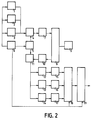
- FIG. 2 shows a block diagram of a radar apparatus in which this type of transmission can be realized.
- Each of the three pulse generators 1, 2, 3 simultaneously generates a transmitter pulse with mutually different frequencies. These transmitter pulses are subsequently applied to a mixer stage 4, which also receives a signal from a synthesizer 5.
- Synthesizer 5 can for instance generate eight different frequencies in the radar band in which the radar apparatus operates, with 5 Mc/s increments.
- control unit 6 which controls the pulse generators 1, 2, 3 and synthesizer 5 in such a manner that, first, combined with the lowest synthesizer frequency, three transmitter pulses with a mutual frequency difference of 1,666 Mc/s are simultaneously generated, and which subsequently observes a listening time, after which the three transmitter pulses are transmitted three times in succession for the purpose of Doppler processing.
- the synthesizer frequency is then increased by 5 Mc/s, after which the following three transmitter pulses are transmitted repeatedly etc.
- the generated transmitter pulses are amplified through a radar transmitter 7 and are supplied to an antenna 9 via a T/R device 8, for instance a circulator. Radar echoes received in antenna 9 are fed to a radar receiver 10 via T/R device 8 and are subsequently fed to a second mixer stage 11, which also receives a signal from synthesizer 5.
- the output signal of mixer stage 11 is applied to three filter circuits 12, 13, 14 which are complementary to the pulse generators 1, 2, 3, to that effect that filter circuit 12 passes only radar echoes from signals generated by pulse generator 1, filter circuit 13 passes only radar echoes from signals generated by pulse generator 2 and filter circuit 14 passes only radar echoes from signals generated by pulse generator 3, such on the basis of the frequency of the signals.
- the originally combined signals of pulse generators 1, 2, 3 can be entirely separated.
- the output signals of filter circuits 12, 13, 14 are subsequently applied to three phase-sensitive detectors 15, 16, 17 to each of which, as is customary with coherent radars, a suitable reference signal is supplied by the pulse generators 1, 2, 3.
- the output signals of the coherent detectors 15, 16, 17 are then applied to an analog-digital convertor 18 which, controlled by control unit 6, samples the output signals on the basis of a known distance to the target, obtained by means of a second radar apparatus or with the same radar apparatus in another operating mode, and which converts the output signals into three complex numbers representing the target strength, which numbers are subsequently applied to a digital computer 19 for further processing.
- the digital computer 19 In order to remove clutter, the digital computer 19 first performs a Doppler processing to the set of 96 complex numbers thus obtained. This results in a set of 24 complex numbers representing the target, which set is subsequently subjected to a Fourier processing to obtain target information with a high range resolution, all this in accordance with procedures known in the art.
- the radar transmitter pulses are not transmitted equidistantly in time, whereas the Fourier processing presumes equidistant transmission, it is necessary to adjust the 24 complex numbers representing the target prior to Fourier processing. Supposing that with respect to the three pulses simultaneously transmitted at t1, the pulse with the lowest frequency f1 is transmitted at the right moment, then the pulse with f2 is transmitted too early by one third of the pulse repetition rate and the pulse with f3 by two thirds of the pulse repetition rate.
- the adjustment can then be easily made on the basis of these times and the known frequencies and is tantamount to a phase correction for the signals with frequencies f2, f3, f5, f6 etc, which adjustment can easily be computed in digital computer 19 and can for instance be integrated in the Doppler processing.
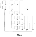
- FIG. 1 shows a block diagram of this second embodiment of the radar apparatus in which this method can be used.
- pulse generator 3 generates three successive transmitter pulses with different frequencies, for instance also with a mutual frequency difference of 1,666. Mc/s.
- a most suitable device for this purpose is a SAW delay line which, triggered by control unit 6 and on the basis of a COHO signal, well-known in the art, can generate the three transmitter pulses. These transmitter pulses are then mixed with the aid of synthesizer 5 and mixer stage 4, are subsequently amplified to full power via radar transmitter 7 and transmitted via T/R device 8 and antenna 9. Upon reception, the radar echoes of the three pulses are again separated by the filter circuits 12, 13, 14 and are supplied to three phase-sensitive detectors 15, 16, 17, which are thereto also supplied with the COHO signal. Further processing is performed completely analogous to the processing described with reference to figure 2, with the exception of the phase correction.
- the pulse with frequency f2 is now transmitted too early by one third of the pulse repetition rate minus the pulse length, after which the phase correction can again be easily computed.
- the pulse with frequency f3 is transmitted too early by two-thirds of the pulse repetition rate minus twice the pulse length.
- Pulse generator 3 of figure 3 can also be implemented as a prior art direct synthesizer where the waveform to be generated is digitally stored in a read-only memory and, triggered by command unit 6, is read and supplied to a digital-analog convertor, followed by a low-pass filter.
- the pulses may be modulated so as to allow pulse compression.
- a suitable type of modulation is a linear FM modulation.
- Actual pulse compression then takes place in filter circuits 12, 13, 14, which are for instance implemented as SAW delay lines. Pulse compression entails the advantage that long pulses can be employed, while it can nevertheless be prevented that multiple targets are simultaneously observed.
Abstract
Description
- Figure 1
- represents a first type of transmission of radar transmitter pulses according to the invention;
- Figure 2
- represents a block diagram of a first embodiment of a radar apparatus in which the method can be employed;
- Figure 3
- represents a block diagram of a second embodiment of a radar apparatus in which the method can be employed.
Claims (12)
- Method for obtaining information regarding at least one target through the transmission of radar transmitter pulses and the subsequent processing, in a receiver and in a processor, of target echoes obtained in the listening intervals between the radar transmitter pulses, in order to observe the target with a predetermined range resolution, in which process K bursts of radar transmitter pulses are transmitted, a different radar transmit frequency is selected for each burst and moreover, within a burst, groups of pulses with N mutually different transmit frequencies are transmitted repeatedly for the purpose of Doppler processing, so that per transmission, K.N. different radar transmit frequencies are transmitted to achieve the predetermined range resolution, characterized in that for the N pulses, the listening intervals at least substantially coincide.
- Method as claimed in claim 1, characterized in that the N pulses are transmitted at least substantially simultaneously.
- Method as claimed in claim 1, characterized in that the N pulses are transmitted at least substantially contiguously.
- Method as claimed in claim 3, characterized in that within a group of N pulses, the frequency difference between two pulses is smaller than the frequency difference between two bursts.
- Method as claimed in claim 4, characterized in that for a group of N pulses, the frequency difference between two pulses is at least substantially a multiple of a first selected frequency difference.
- Method as claimed in claim 5, characterized in that for the K bursts, the frequency difference between two bursts is at least substantially a multiple of a second selected frequency difference.
- Method as claimed in claim 6, characterized in that the second frequency difference amounts at least substantially N times the first frequency difference.
- Method as claimed in claim 4, characterized in that the target echoes of the N pulses with the N different frequencies are processed simultaneously in a single receiver channel.
- Method as claimed in claim 8, characterized in that target echoes of the N pulses are passed to N filter circuits connected to the receiver channel.
- Method as claimed in claim 9, characterized in that the target echoes in the various filter circuits are moreover delayed to such an extent that corresponding target echoes appear shifted in time at the various filter circuit outputs, so that it seems as if the N pulses were transmitted as a succession of pulses transmitted equidistantly in time.
- Radar apparatus for obtaining information regarding at least one target, comprising a radar transmitter, an antenna, a radar receiver, for the generation and transmission of radar transmitter pulses and the reception of target echoes, the radar apparatus being designed for the transmission of K bursts of radar transmitter pulses with mutually different radar transmit frequencies and for the repeated transmission, within a burst, of groups of N pulses with mutually different radar transmit frequencies, such that per transmission, K.N. different radar transmit frequencies are transmitted to achieve a selected range resolution, characterized in that the radar apparatus is designed for the simultaneous or at least substantially contiguous transmission of the N pulses within a group.
- Radar apparatus as claimed in claim 11, characterized in that the radar receiver is designed for substantially simultaneous processing of target echoes of the N pulses within a group.
Applications Claiming Priority (2)
| Application Number | Priority Date | Filing Date | Title |
|---|---|---|---|
| NL1004798 | 1996-12-17 | ||
| NL1004798A NL1004798C2 (en) | 1996-12-17 | 1996-12-17 | METHOD FOR TRANSMITTING RADAR TRANSMISSION PULSES |
Publications (2)
| Publication Number | Publication Date |
|---|---|
| EP0849606A1 true EP0849606A1 (en) | 1998-06-24 |
| EP0849606B1 EP0849606B1 (en) | 2005-10-12 |
Family
ID=19764066
Family Applications (1)
| Application Number | Title | Priority Date | Filing Date |
|---|---|---|---|
| EP97203785A Expired - Lifetime EP0849606B1 (en) | 1996-12-17 | 1997-12-03 | Method for the transmission of radar transmitter pulses |
Country Status (6)
| Country | Link |
|---|---|
| US (1) | US5943004A (en) |
| EP (1) | EP0849606B1 (en) |
| AU (1) | AU724008B2 (en) |
| CA (1) | CA2225019C (en) |
| DE (1) | DE69734345T2 (en) |
| NL (1) | NL1004798C2 (en) |
Cited By (2)
| Publication number | Priority date | Publication date | Assignee | Title |
|---|---|---|---|---|
| EP1634095A2 (en) * | 2003-05-22 | 2006-03-15 | General Atomics | Ultra-wideband radar system using sub-band coded pulses |
| US10114116B2 (en) * | 2014-08-19 | 2018-10-30 | Navico Holding As | Common burst for pulse compression radar |
Families Citing this family (5)
| Publication number | Priority date | Publication date | Assignee | Title |
|---|---|---|---|---|
| NL1012373C2 (en) * | 1999-06-17 | 2000-12-19 | Hollandse Signaalapparaten Bv | Radar device. |
| GB0228731D0 (en) * | 2002-12-10 | 2003-01-15 | Trw Ltd | Frequency shift keying radar with ambiguity detection |
| CA2526133C (en) * | 2003-05-22 | 2012-04-10 | General Atomics | Ultra-wideband radar system using sub-band coded pulses |
| JP5398306B2 (en) * | 2009-03-04 | 2014-01-29 | 古野電気株式会社 | Radar equipment |
| US10222454B2 (en) * | 2014-08-19 | 2019-03-05 | Navico Holding As | Combining Reflected Signals |
Citations (3)
| Publication number | Priority date | Publication date | Assignee | Title |
|---|---|---|---|---|
| GB2134741A (en) * | 1983-01-31 | 1984-08-15 | Decca Ltd | Radar apparatus |
| US5347283A (en) * | 1989-06-14 | 1994-09-13 | Hughes Aircraft Company | Frequency agile radar |
| EP0706061A2 (en) * | 1994-10-04 | 1996-04-10 | Telefonaktiebolaget Lm Ericsson | Method for the control of a radar station |
Family Cites Families (3)
| Publication number | Priority date | Publication date | Assignee | Title |
|---|---|---|---|---|
| US3787853A (en) * | 1967-03-31 | 1974-01-22 | Raytheon Co | Coded multiple frequency signal system |
| US4450444A (en) * | 1981-05-29 | 1984-05-22 | The United States Of America As Represented By The Secretary Of The Navy | Stepped frequency radar target imaging |
| US4743910A (en) * | 1986-12-16 | 1988-05-10 | Hughes Aircraft Company | Frequency domain, pulse compression radar apparatus for eliminating clutter |
-
1996
- 1996-12-17 NL NL1004798A patent/NL1004798C2/en not_active IP Right Cessation
-
1997
- 1997-12-03 EP EP97203785A patent/EP0849606B1/en not_active Expired - Lifetime
- 1997-12-03 DE DE69734345T patent/DE69734345T2/en not_active Expired - Lifetime
- 1997-12-08 AU AU46928/97A patent/AU724008B2/en not_active Expired
- 1997-12-12 US US08/990,090 patent/US5943004A/en not_active Expired - Lifetime
- 1997-12-16 CA CA002225019A patent/CA2225019C/en not_active Expired - Lifetime
Patent Citations (3)
| Publication number | Priority date | Publication date | Assignee | Title |
|---|---|---|---|---|
| GB2134741A (en) * | 1983-01-31 | 1984-08-15 | Decca Ltd | Radar apparatus |
| US5347283A (en) * | 1989-06-14 | 1994-09-13 | Hughes Aircraft Company | Frequency agile radar |
| EP0706061A2 (en) * | 1994-10-04 | 1996-04-10 | Telefonaktiebolaget Lm Ericsson | Method for the control of a radar station |
Cited By (4)
| Publication number | Priority date | Publication date | Assignee | Title |
|---|---|---|---|---|
| EP1634095A2 (en) * | 2003-05-22 | 2006-03-15 | General Atomics | Ultra-wideband radar system using sub-band coded pulses |
| EP1634095A4 (en) * | 2003-05-22 | 2007-02-28 | Gen Atomics | Ultra-wideband radar system using sub-band coded pulses |
| US10114116B2 (en) * | 2014-08-19 | 2018-10-30 | Navico Holding As | Common burst for pulse compression radar |
| US10120069B2 (en) | 2014-08-19 | 2018-11-06 | Navico Holding As | Multiple ranges for pulse compression radar |
Also Published As
| Publication number | Publication date |
|---|---|
| CA2225019C (en) | 2008-12-02 |
| DE69734345T2 (en) | 2006-07-13 |
| US5943004A (en) | 1999-08-24 |
| AU724008B2 (en) | 2000-09-07 |
| CA2225019A1 (en) | 1998-06-17 |
| NL1004798C2 (en) | 1998-06-18 |
| EP0849606B1 (en) | 2005-10-12 |
| DE69734345D1 (en) | 2005-11-17 |
| AU4692897A (en) | 1998-06-18 |
Similar Documents
| Publication | Publication Date | Title |
|---|---|---|
| JP2545958B2 (en) | Digital beamforming radar | |
| AU2005242826B2 (en) | System and method for concurrent operation of multiple radar or active sonar systems on a common frequency | |
| RU2413958C2 (en) | Radar apparatus | |
| US20080088499A1 (en) | Methods and apparatus for hyperview automotive radar | |
| EP2876460B1 (en) | A vehicle radar with two transmitter antenna arrangements | |
| EP0389720B1 (en) | Radar detection of targets at short and long range | |
| JP2010538251A (en) | Digital radar or sonar device | |
| US6184820B1 (en) | Coherent pulse radar system | |
| JP2008501978A (en) | Short pulse / step frequency radar system | |
| JP2004535562A (en) | A pulse radar that changes the frequency spectrum interval irregularly for each pulse when an interference signal is detected | |
| EP0928427B1 (en) | Radar systems | |
| EP0027122B1 (en) | Monopulse radar with pilot signal generator | |
| CA2009601A1 (en) | Blind speed elimination for dual displaced phase center antenna radar processor mounted on a moving platform | |
| EP0849606B1 (en) | Method for the transmission of radar transmitter pulses | |
| GB2214026A (en) | Radar apparatus employing different kinds of pulses | |
| US4060806A (en) | Phased array radars | |
| US4496949A (en) | MTI Radar adaptable to different environmental conditions | |
| US7755538B2 (en) | Radar apparatus | |
| GB2134741A (en) | Radar apparatus | |
| GB2115252A (en) | Pulse doppler radar units | |
| JP2656097B2 (en) | Radar equipment | |
| US5061933A (en) | Short-range radar system | |
| US4014020A (en) | Automatic gain control circuit for high range resolution correlation radar | |
| JP2000275330A (en) | Doppler radar apparatus and transmission method for radar pulses | |
| JP2579353B2 (en) | Digital beamforming radar |
Legal Events
| Date | Code | Title | Description |
|---|---|---|---|
| PUAI | Public reference made under article 153(3) epc to a published international application that has entered the european phase |
Free format text: ORIGINAL CODE: 0009012 |
|
| AK | Designated contracting states |
Kind code of ref document: A1 Designated state(s): BE CH DE FR GB LI NL SE |
|
| AX | Request for extension of the european patent |
Free format text: AL;LT;LV;MK;RO;SI |
|
| 17P | Request for examination filed |
Effective date: 19981228 |
|
| AKX | Designation fees paid |
Free format text: BE CH DE FR GB LI NL SE |
|
| RBV | Designated contracting states (corrected) |
Designated state(s): BE CH DE FR GB LI NL SE |
|
| RAP1 | Party data changed (applicant data changed or rights of an application transferred) |
Owner name: THALES NEDERLAND B.V. |
|
| 17Q | First examination report despatched |
Effective date: 20020201 |
|
| GRAP | Despatch of communication of intention to grant a patent |
Free format text: ORIGINAL CODE: EPIDOSNIGR1 |
|
| GRAS | Grant fee paid |
Free format text: ORIGINAL CODE: EPIDOSNIGR3 |
|
| GRAA | (expected) grant |
Free format text: ORIGINAL CODE: 0009210 |
|
| AK | Designated contracting states |
Kind code of ref document: B1 Designated state(s): BE CH DE FR GB LI NL SE |
|
| PG25 | Lapsed in a contracting state [announced via postgrant information from national office to epo] |
Ref country code: BE Free format text: LAPSE BECAUSE OF FAILURE TO SUBMIT A TRANSLATION OF THE DESCRIPTION OR TO PAY THE FEE WITHIN THE PRESCRIBED TIME-LIMIT Effective date: 20051012 |
|
| REG | Reference to a national code |
Ref country code: GB Ref legal event code: FG4D |
|
| REG | Reference to a national code |
Ref country code: CH Ref legal event code: EP |
|
| REF | Corresponds to: |
Ref document number: 69734345 Country of ref document: DE Date of ref document: 20051117 Kind code of ref document: P |
|
| REG | Reference to a national code |
Ref country code: SE Ref legal event code: TRGR |
|
| ET | Fr: translation filed | ||
| PLBE | No opposition filed within time limit |
Free format text: ORIGINAL CODE: 0009261 |
|
| STAA | Information on the status of an ep patent application or granted ep patent |
Free format text: STATUS: NO OPPOSITION FILED WITHIN TIME LIMIT |
|
| 26N | No opposition filed |
Effective date: 20060713 |
|
| REG | Reference to a national code |
Ref country code: FR Ref legal event code: PLFP Year of fee payment: 19 |
|
| REG | Reference to a national code |
Ref country code: FR Ref legal event code: PLFP Year of fee payment: 20 |
|
| PGFP | Annual fee paid to national office [announced via postgrant information from national office to epo] |
Ref country code: NL Payment date: 20161212 Year of fee payment: 20 Ref country code: FR Payment date: 20161128 Year of fee payment: 20 Ref country code: CH Payment date: 20161213 Year of fee payment: 20 Ref country code: DE Payment date: 20161129 Year of fee payment: 20 Ref country code: GB Payment date: 20161125 Year of fee payment: 20 |
|
| PGFP | Annual fee paid to national office [announced via postgrant information from national office to epo] |
Ref country code: SE Payment date: 20161213 Year of fee payment: 20 |
|
| REG | Reference to a national code |
Ref country code: DE Ref legal event code: R071 Ref document number: 69734345 Country of ref document: DE |
|
| REG | Reference to a national code |
Ref country code: NL Ref legal event code: MK Effective date: 20171202 |
|
| REG | Reference to a national code |
Ref country code: CH Ref legal event code: PL |
|
| REG | Reference to a national code |
Ref country code: GB Ref legal event code: PE20 Expiry date: 20171202 |
|
| REG | Reference to a national code |
Ref country code: SE Ref legal event code: EUG |
|
| PG25 | Lapsed in a contracting state [announced via postgrant information from national office to epo] |
Ref country code: GB Free format text: LAPSE BECAUSE OF EXPIRATION OF PROTECTION Effective date: 20171202 |