EP0850133B1 - Sizing apparatus - Google Patents
Sizing apparatus Download PDFInfo
- Publication number
- EP0850133B1 EP0850133B1 EP96929974A EP96929974A EP0850133B1 EP 0850133 B1 EP0850133 B1 EP 0850133B1 EP 96929974 A EP96929974 A EP 96929974A EP 96929974 A EP96929974 A EP 96929974A EP 0850133 B1 EP0850133 B1 EP 0850133B1
- Authority
- EP
- European Patent Office
- Prior art keywords
- sizing sleeve
- tube
- fluid
- sizing
- pressure
- Prior art date
- Legal status (The legal status is an assumption and is not a legal conclusion. Google has not performed a legal analysis and makes no representation as to the accuracy of the status listed.)
- Expired - Lifetime
Links
Images


Classifications
-
- B—PERFORMING OPERATIONS; TRANSPORTING
- B29—WORKING OF PLASTICS; WORKING OF SUBSTANCES IN A PLASTIC STATE IN GENERAL
- B29C—SHAPING OR JOINING OF PLASTICS; SHAPING OF MATERIAL IN A PLASTIC STATE, NOT OTHERWISE PROVIDED FOR; AFTER-TREATMENT OF THE SHAPED PRODUCTS, e.g. REPAIRING
- B29C48/00—Extrusion moulding, i.e. expressing the moulding material through a die or nozzle which imparts the desired form; Apparatus therefor
- B29C48/25—Component parts, details or accessories; Auxiliary operations
- B29C48/88—Thermal treatment of the stream of extruded material, e.g. cooling
- B29C48/90—Thermal treatment of the stream of extruded material, e.g. cooling with calibration or sizing, i.e. combined with fixing or setting of the final dimensions of the extruded article
- B29C48/901—Thermal treatment of the stream of extruded material, e.g. cooling with calibration or sizing, i.e. combined with fixing or setting of the final dimensions of the extruded article of hollow bodies
- B29C48/903—Thermal treatment of the stream of extruded material, e.g. cooling with calibration or sizing, i.e. combined with fixing or setting of the final dimensions of the extruded article of hollow bodies externally
-
- B—PERFORMING OPERATIONS; TRANSPORTING
- B29—WORKING OF PLASTICS; WORKING OF SUBSTANCES IN A PLASTIC STATE IN GENERAL
- B29C—SHAPING OR JOINING OF PLASTICS; SHAPING OF MATERIAL IN A PLASTIC STATE, NOT OTHERWISE PROVIDED FOR; AFTER-TREATMENT OF THE SHAPED PRODUCTS, e.g. REPAIRING
- B29C48/00—Extrusion moulding, i.e. expressing the moulding material through a die or nozzle which imparts the desired form; Apparatus therefor
- B29C48/03—Extrusion moulding, i.e. expressing the moulding material through a die or nozzle which imparts the desired form; Apparatus therefor characterised by the shape of the extruded material at extrusion
- B29C48/09—Articles with cross-sections having partially or fully enclosed cavities, e.g. pipes or channels
-
- B—PERFORMING OPERATIONS; TRANSPORTING
- B29—WORKING OF PLASTICS; WORKING OF SUBSTANCES IN A PLASTIC STATE IN GENERAL
- B29C—SHAPING OR JOINING OF PLASTICS; SHAPING OF MATERIAL IN A PLASTIC STATE, NOT OTHERWISE PROVIDED FOR; AFTER-TREATMENT OF THE SHAPED PRODUCTS, e.g. REPAIRING
- B29C48/00—Extrusion moulding, i.e. expressing the moulding material through a die or nozzle which imparts the desired form; Apparatus therefor
- B29C48/25—Component parts, details or accessories; Auxiliary operations
- B29C48/88—Thermal treatment of the stream of extruded material, e.g. cooling
- B29C48/90—Thermal treatment of the stream of extruded material, e.g. cooling with calibration or sizing, i.e. combined with fixing or setting of the final dimensions of the extruded article
- B29C48/904—Thermal treatment of the stream of extruded material, e.g. cooling with calibration or sizing, i.e. combined with fixing or setting of the final dimensions of the extruded article using dry calibration, i.e. no quenching tank, e.g. with water spray for cooling or lubrication
-
- B—PERFORMING OPERATIONS; TRANSPORTING
- B29—WORKING OF PLASTICS; WORKING OF SUBSTANCES IN A PLASTIC STATE IN GENERAL
- B29C—SHAPING OR JOINING OF PLASTICS; SHAPING OF MATERIAL IN A PLASTIC STATE, NOT OTHERWISE PROVIDED FOR; AFTER-TREATMENT OF THE SHAPED PRODUCTS, e.g. REPAIRING
- B29C48/00—Extrusion moulding, i.e. expressing the moulding material through a die or nozzle which imparts the desired form; Apparatus therefor
- B29C48/25—Component parts, details or accessories; Auxiliary operations
- B29C48/88—Thermal treatment of the stream of extruded material, e.g. cooling
- B29C48/90—Thermal treatment of the stream of extruded material, e.g. cooling with calibration or sizing, i.e. combined with fixing or setting of the final dimensions of the extruded article
- B29C48/908—Thermal treatment of the stream of extruded material, e.g. cooling with calibration or sizing, i.e. combined with fixing or setting of the final dimensions of the extruded article characterised by calibrator surface, e.g. structure or holes for lubrication, cooling or venting
-
- B—PERFORMING OPERATIONS; TRANSPORTING
- B29—WORKING OF PLASTICS; WORKING OF SUBSTANCES IN A PLASTIC STATE IN GENERAL
- B29C—SHAPING OR JOINING OF PLASTICS; SHAPING OF MATERIAL IN A PLASTIC STATE, NOT OTHERWISE PROVIDED FOR; AFTER-TREATMENT OF THE SHAPED PRODUCTS, e.g. REPAIRING
- B29C48/00—Extrusion moulding, i.e. expressing the moulding material through a die or nozzle which imparts the desired form; Apparatus therefor
- B29C48/25—Component parts, details or accessories; Auxiliary operations
- B29C48/88—Thermal treatment of the stream of extruded material, e.g. cooling
- B29C48/911—Cooling
- B29C48/9115—Cooling of hollow articles
- B29C48/912—Cooling of hollow articles of tubular films
- B29C48/913—Cooling of hollow articles of tubular films externally
Definitions
- the present invention relates to a sizing sleeve arrangement for controlling the outer diameter of a plastic tube being produced by a continuous tube forming process such as extrusion, or by an expansion process such as that generally described in WO-A-9002644, wherein the tube at least in the region of the sizing sleeve is under positive internal pressure.
- sizing sleeves for tube diameter control with passages allowing the injection of lubricating water between the sleeve and the travelling tube, for example as achieved by a helical channel about the sleeve as described in WO-A-91 04 147 and EP-A2-0 385 285.
- these sizing sleeves may also have apertures in the sizing sleeve for applying a vacuum to the outside of the tube.
- Document GB 1 154 259 discloses an apparatus for sizing and cooling a plastic extrudate in accordance with the preamble of appended claim 1, wherein the sleeve is axially segmented into high and low pressure portions, such that lubricating fluid supplied by the high pressure portion forms a layer between the sizing sleeve and the plastic extrudate and is drained at the low pressure portions.
- the present invention provides a sizing sleeve according to appended claim 1.
- the solution proposed has the advantage that very fine injection apertures can be produced the size and shape of which can be carefully controlled.
- the extruded tube 2 is formed to approximately the desired outside diameter, but requires calibration to ensure conformance to required specifications. While the material of the tube is still sufficiently plastic to be shaped, the tube approaches a sizing apparatus for fine control of the final outside diameter.
- the extruded tube is under positive internal pressure, thus pressing the tube against the cylindrical inner surface of the sizing apparatus. Cooling is applied to the extruded tube within and downstream of the sizing apparatus to lock in the final diameter.
- the illustrated sizing sleeve means consists of a plurality of pressurised sizing sleeve portions 10 alternated with drainage zones 12.
- each drainage zone may be a small gap between adjacent pressurised portions 10 of the sizing sleeve means, allowing sufficient area for the water injected in the previous pressurised portion to escape and isolating adjacent pressurised portions but insufficient unsupported length to allow substantial outwards creep of the tube.
- Each pressurised portion 10 is formed as a jacketed tube, the inner tube 14 being perforated with a large number of injection apertures 16. Cool water from a high pressure source 17 is introduced under pressure to the annular manifold space between the inner 14 and outer 18 tubes and is injected through the apertures 16 to form a fine layer of water which both lubricates the movement of the tube past the inner surface of the sizing sleeve and cools the outside of the tube to lock in the final tube diameter.
- the sizing sleeve means is also adapted for the situation where the tube entering the sizing sleeve is not at its extruded diameter, but is instead being diametrically expanded in order to impart circumferential orientation of the polymer molecules.
- the tube is expanded by means internal fluid pressure restrained by an inflatable plug.
- a sizing sleeve according to the invention may be located at the downstream limit of expansion of the tube in order to provide final diameter control of the expanded tube.
- the separation of the pressurised portions 10 by drainage zones 12 allows the injected water from the upstream pressurised portion to escape, preventing build up of water between the tube and the sleeve inner surface, which can result in fluctuations in diameter of the resultant tube.
- the drainage zones further allow isolation of pressure zones and limit or eliminate pressure communication between them.
- the present applicants have found that, if this is not the case, an oscillatory system can be set up due to interactions between axially moving deformations on the tube and the pressure field within the injected fluid. Isolation of pressure zones allows the pressure profile to be set and maintained at a specified profile without "cross-talk" or interference between zones.
- the pressure of the fluid layer between the sleeve inner surface and the tube will be substantially equal to the internal pressure in the tube less a component due to the elastic and viscous resistance of the tube wall.
- the wall thickness of the tube being extruded will typically vary by ⁇ 10%, which will cause variation of a similar magnitude in the elastic and viscous resistance to the internal pressure.
- the tube wall resists a large component, typically 60-90%, of the internal pressure, and the lubricating layer pressure is therefore only the remaining 10-40%, the 10% variation in resistance translates to about ⁇ 50% variation in the lubricating layer pressure.
- the sizing apparatus preferably includes injection fluid flow rate stabilising means which substantially reduces variation in the rate of fluid injection caused by pressure variations of the lubricating layer.
- the fluid flow rate stabilising means causes a 50% variation in the lubricating layer pressure to result in less than 20%, preferably less than 10%, variation in the injection rate.
- the flow rate stabilising means can control the fluid supply to the injection apertures 16, for example comprising a flow control device 28 (see Fig. 2) placed in the fluid supply lines to each of the pressurised portions 10.
- the flow control device 28 may be high pressure drop constriction, such as an orifice, provided with substantial excess pressure at its upstream side so that normal variations in pressure at the downstream side have little effect on the flow rate through the device.
- the pressure drop caused by the constriction device should be greater than the lubricating layer pressure.
- the pressure provided by the fluid source is preferably at least 100% and most desirably at least 150% of the maximum internal pressure, at least in the pressurised portion adjacent the entry end of the sizing sleeve.
- the tube wall is in a plastic state and the elastic resistance to the internal pressure is at its lowest, but will still counteract a very significant proportion of the internal pressure and thus the fluid source pressure will be substantially greater than the lubricating layer pressure.
- the outer surface of the tube is cooled by the fluid film and the thickness of the outer hardened portion of the tube progressively increases until the tube no longer requires diametral support from the film pressure to hold its diameter under the stress of the internal pressure.
- the fluid supply pressure can be reduced progressively along the sizing sleeve if desired.
- the high pressure source and orifice may be substituted by a mechanical flow control device which adjusts to keep the flow rate relatively constant.
- the drainage zones can be simply a gap 12 between adjacent pressurised sleeve portions, as shown in Fig. 1.
- the drainage zones can be part of a continuous sizing sleeve, as shown in Fig. 2.
- the sizing sleeve is formed as a jacketed tube, the inner tube having a plurality of apertures or circumferential slots 26 therethrough.
- the region between the inner and outer tubes is divided into a plurality of regions 20 by a series of radial walls 22, with each region having a spigot 24 or other means for connection of fluid supply/outlet tubes.
- the regions 20a to which a supply of fluid under pressure is connected act as pressurised portions as in Fig. 1, while those regions 20b to which fluid outlet tubes are connected act as collection manifolds and thus drainage zones.
- pressurised portions 10 have a length consisting of two successive regions, followed by drainage zones of one region.
- each sizing sleeve portion are relatively large, for example at least 1mm per 100mm tube diameter or a circumferential slot 26 to present minimal pressure drop to the fluid injection and drainage.
- the pressure of the manifold is therefore approximately equal to the lubrication layer pressure.
- Each pressurised manifold is connected to the high pressure fluid source 17 via a flow stabilising means 28 as discussed above. It is preferred that each manifold is connected to the source 17 via a separate flow stabiliser 28, so that fluctuations in tube wall thickness will not cause one chamber to inject excessive water at the expense of the other chambers.
- the injection slots 26 or apertures can be divided into a number of circumferential sectors and the fluid supply to each sector made independent by providing each with its own flow stabiliser.
- each sector can be provided with a separate fluid supply.
- This latter arrangement can be used to control fluid supply pressure to each part of the sleeve circumference independently.
- the applicant has determined that the eccentricity in the circularity and wall thickness of the tube approaching the sizing device is often caused by pin offset in the extruder head producing the tube. Such eccentricity is regular and predictable, and thus may be amenable to compensation by independent control of the injection fluid in the sizing device in a number, for example three to eight, of circumferential sectors.
- An alternative means of attaining flow stability is to inject fluid through a large number of fine apertures, for example less than about 0.5mm and more preferably less than about 0.25mm in hydraulic diameter.
- flow stability may be achieved using apertures of hydraulic diameter less than 0.5% of the tube diameter.
- the use of high pressure drop injection apertures and a high pressure fluid source as the flow stabilising means has the advantage of stabilising the fluid injection about the sizing sleeve circumference as well as stability of the overall fluid flow into the sizing sleeve.
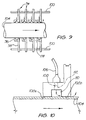
- Figs. 3 to 5 illustrate a modular sizing sleeve construction according to a further embodiment, which facilitates the formation of fine injection apertures.
- the sizing sleeve is formed of a series of segments 30 each integrally comprising an inner ring portion 32, a bridging portion 24 at one end, and an outer coaxial ring portion 36 with an inlet or outlet aperture 37.
- the inner and outer ring portions are offset axially and radially from each other, so that the fitting segments together forms a substantially continuous sizing sleeve surface surrounded by a series of annular manifolds 38.
- Each manifold is sealed against external leakage by an o-ring 40 in a groove 42 in one segment contacting a surface of the next segment, and the segments are held in place by a clamping arrangement consisting of a pair of clamping rings 44, 46 joined by a series of tie bars 48.
- the upstream clamping ring 44 may have an inner surface 50 acting as a lead in portion for the sizing sleeve, having a rounded entry part 52 formed of polymer material such as high density polyethylene (HDPE).
- HDPE high density polyethylene
- each inner ring portion abuts the bridging portion rear face 54 of the adjoining segment, and has a series of radial grooves 56 milled therein.
- these grooves serve as the injection apertures for injection of the fluid to the inside of the sizing sleeve.
- An advantage of this construction is that the size and shape of the injection apertures can be carefully controlled because the manufacture involves cutting notches into an end surface of each segment rather than laser or physical drilling through the body of the sizing sleeve. Very fine apertures can be produced, for example triangular notches about 0.1 - 0.2mm deep and 0.1 - 0.3mm wide (see Fig. 5), by conventional machining techniques.
- Another advantage of this construction is the ability to dismantle and clean the sizing sleeve in the event of blockage of the injection apertures.
- each segment to be used as a drainage zone may be spaced by a small amount, for example 0.2 - 2mm, from the previous segment by a spacing member such as a shim in order to create a circumferential drainage slot of that width.
- the sizing sleeve may consist of twelve such segments and have each fourth segment spaced by 0.5mm to act as a drainage zone.
- special drainage segments can be provided, having a larger aperture area than the injection segments.
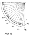
- Figs. 6 to 7B illustrates an alternative modular sizing sleeve, which allows water to be injected at several places along the length of each segment.
- the arrangement is particularly adapted for use as the first pressurised portion of the sizing sleeve, where cooling and lubrication requirements are high, but if required this construction may be extended along the length of the sizing sleeve.
- the structure of the sizing sleeve is formed by a number of overlapping segments, each containing a fluid inlet or drainage connection 37.
- the second and subsequent segment 30b integrate the inner part 58, forming the inner surface of the sizing sleeve, with the outer part 60 which includes the fluid connection 37.
- the end surface 62 of the inner part is notched as described above for Figs. 4 to 6, to form injection or drainage apertures, and fluid passages 64 lead from the apertures 66 to the fluid connection 37.
- the first segment 30a consists of an outer support ring 68 which mates with the second segment and has the fluid inlet 37, and a series of shorter inner rings 70 fitted inside to form the sizing sleeve inner surface.
- the inner rings have aligned bores 72 running therethrough at angularly spaced locations.
- the inner rings also have radial grooves 66 in their end surfaces and are chamfered at their outer edges so that, when adjacent rings are abutted together the adjacent chamfers form a circumferential fluid distribution channel 74 communicating with the radial channels formed by the grooves.
- the bore 72 through each ring 70 is flared to provide fluid communication with the circumferential channels and thus provide fluid to the injection apertures.
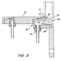
- Fig. 8 illustrates an alternative entry arrangement for the sizing sleeve, incorporating an adjustable width fluid injection aperture.
- the illustrated entry arrangement is fitted to a sizing sleeve comprising segments of the type designated by reference numeral 30b in Fig. 7A, but is suitable for use with sizing sleeves of other types.
- a forwardly facing channel ring 76 has a flange 78 extending inwards to align with the inner surface of the sizing sleeve, with an inwardly angled front surface 80 surrounding the sizing sleeve opening.
- the outer part of the channel incorporates the fluid inlet port 82 for providing water to the manifold 84 defined within the channel.
- the front of the channel is closed off by an externally threaded entry flange 86 which screws into engagement with a fine internal thread 88 on the outer part of the channel.
- the front surface of the entry flange includes a frustoconical lead in portion 90 which extends inwards to a diameter slightly smaller, for example up to 1mm or more preferably about 0.2mm, than that of the sizing sleeve inner surface.
- the smaller diameter lip functions as a seal with the plastic tube which bears against it with a high pressure.
- the contact surface 91 should preferably have a hard coating such as DLC (diamond-like coating).
- the entry flange rear surface is parallel to the front surface 80 of the inwards flange 78 to create a circular fluid injection slot. This injects the lubricating water behind the overhanging lip of the lead in portion 90 to form a lubricating layer which is carried along by the travelling tube.
- the width of the slot 92, and therefore the amount of liquid injected as the lubricating layer, may be adjusted by screwing the threaded flange 86 in or out relative to the channel ring 76.
- Fluid injected in a first portion of the sizing sleeve may be at a higher temperature than the fluid injected further downstream, so that the tube travel in the initial part of the sizing sleeve is lubricated without cooling the tube so that it more readily adopts the shape of the sizing sleeve.
- the injection fluid both lubricates and cools the tube.
- each pressurised sizing sleeve portion may have a separate fluid source with independently controllable temperature and pressure.
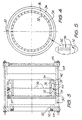
- Figs. 9 and 10 show a further embodiment of a modular sizing sleeve, in which each segment 94 consists of an inwards facing circumferential channel 96 with an outwards supporting flange 98.
- An array of the axial rods 100 pass through the support flanges 98 of the segments to hold them in an axially spaced formation.
- Each channel ring includes a pair of hardened inner surfaces 102a, 102b serving as sizing sleeve surfaces for supporting the travelling tube 104, and has a fluid supply 106, and injection aperture 108 leading to the annular space 110 defined between the channel and the tube.
- the injection fluid is supplied under pressure to this annular space 110 to support the tube in this region.
- the water flow through the apertures 108 may be adjustable by means of a threaded adjustment member 112 as best seen in Fig. 10.
- the space 114 between the adjacent segments forms the drainage zone of the sizing sleeve, with the relative proportions of the injection and drainage zones being adjustable by changing the spacing of the segments.
- the sizing sleeve solid surface area, surfaces 102a and 102b may be approximately equal to the remaining area presented by the spaces 110 and 114.
- the temperature control may predominantly be carried out by the cooling water rather than the injection water and application of vacuum to the tube exterior in the drainage zones is easily achieved. Warm water may be injected to the first segments to assist the tube to adopt the sizing sleeve diameter.
Abstract
Description
Claims (13)
- A sizing sleeve for controlling the outer diameter of an internally pressurised plastic tube (2) travelling through the sizing sleeve, the sizing sleeve having an upstream and a downstream end relative to the tube travel, including at least two pressurised sizing sleeve portions each having means for injecting fluid under pressure substantially about the circumference of the tube (2) to form a lubricating fluid layer between a sizing sleeve inner surface and the tube (2), the pressurised! sizing sleeve portions are axially separated and isolated from each other by a drainage zone, characterised in that each pressurised sizing sleeve portion comprises an inner sizing sleeve member having a plurality of coaxial rings (30) arranged end-to-end and each having a plurality of injection apertures (56) extending thereacross, and an annular injection fluid manifold (38) radially surrounding the inner sizing sleeve member, receiving fluid from a fluid supply means and communicating with said injection apertures (56), the injection apertures (56) being formed between end surfaces (54) of adjacent rings, said injection apertures being formed by grooves in one or more of said end surfaces (54), and said grooves communicating with said fluid supply means and extending to the sizing sleeve inner surface.
- The sizing sleeve according to claim 1, characterised in that said grooves (54) extend substantially radially across said end surface.
- A sizing sleeve according to claim 1 or 2, characterised in that the injection apertures (56) cause a sufficiently high pressure differential between the manifold (38) and the lubricating fluid layer so that a 50% variation in pressure of the lubricating fluid layer causes less than 20% variation in the rate of fluid injection through said apertures (56).
- A sizing sleeve according to claim 3, characterised in that pressure in said manifold (38) exceeds the internal pressure in said tube (2).
- A sizing sleeve according to claim 4, characterised in that manifold pressure exceeds 150% of the internal pressure in said tube (2).
- A sizing sleeve according to any one of claims 3 to 5, characterised in that said injection apertures (56) have a diameter less than 0.5 mm.
- A sizing sleeve according to claim 6, characterised in that said injection apertures (56) have a diameter less than 0.25 mm.
- A sizing sleeve according to any one of the preceding claims, characterised in that the sizing sleeve includes an entry portion (86) which projects radially inwards of said sizing sleeve inner surface.
- A sizing sleeve according to claim 8, characterised in that it includes means (84) for injecting said fluid behind said inwardly projecting entry portion (86).
- A sizing sleeve according to claim 9, characterised in that said injecting means includes a circumferential slot (92) located behind said entry portion (86).
- A sizing sleeve according to claim 10, characterised in that it includes a screw connection (88) between said entry portion (86) and a manifold to adjust the area of said slot.
- A sizing sleeve according to claim 8, characterised in that said entry portion (86) includes a hardened contact surface (91) having a diamond-like coating.
- A sizing sleeve according to any one of the preceding claims, characterised in that the coaxial rings (30) are held in place by a clamping arrangement consisting of a pair of clamping rings (44, 46) joined by a series of tie bars (48).
Applications Claiming Priority (4)
| Application Number | Priority Date | Filing Date | Title |
|---|---|---|---|
| AUPN547495 | 1995-09-15 | ||
| AUPN5474A AUPN547495A0 (en) | 1995-09-15 | 1995-09-15 | Sizing apparatus |
| AUPN0547/49 | 1995-09-15 | ||
| PCT/AU1996/000585 WO1997010093A1 (en) | 1995-09-15 | 1996-09-16 | Sizing apparatus |
Publications (3)
| Publication Number | Publication Date |
|---|---|
| EP0850133A1 EP0850133A1 (en) | 1998-07-01 |
| EP0850133A4 EP0850133A4 (en) | 1998-12-23 |
| EP0850133B1 true EP0850133B1 (en) | 2002-01-23 |
Family
ID=3789801
Family Applications (1)
| Application Number | Title | Priority Date | Filing Date |
|---|---|---|---|
| EP96929974A Expired - Lifetime EP0850133B1 (en) | 1995-09-15 | 1996-09-16 | Sizing apparatus |
Country Status (15)
| Country | Link |
|---|---|
| US (1) | US6050800A (en) |
| EP (1) | EP0850133B1 (en) |
| JP (1) | JP4316009B2 (en) |
| CN (1) | CN1063127C (en) |
| AT (1) | ATE212284T1 (en) |
| AU (2) | AUPN547495A0 (en) |
| BR (1) | BR9610595A (en) |
| CA (1) | CA2231873C (en) |
| DE (1) | DE69618794T2 (en) |
| ES (1) | ES2170260T3 (en) |
| NO (1) | NO313818B1 (en) |
| NZ (1) | NZ316855A (en) |
| PT (1) | PT850133E (en) |
| RU (1) | RU2171180C2 (en) |
| WO (1) | WO1997010093A1 (en) |
Cited By (7)
| Publication number | Priority date | Publication date | Assignee | Title |
|---|---|---|---|---|
| US7273655B2 (en) | 1999-04-09 | 2007-09-25 | Shojiro Miyake | Slidably movable member and method of producing same |
| US7650976B2 (en) | 2003-08-22 | 2010-01-26 | Nissan Motor Co., Ltd. | Low-friction sliding member in transmission, and transmission oil therefor |
| US7771821B2 (en) | 2003-08-21 | 2010-08-10 | Nissan Motor Co., Ltd. | Low-friction sliding member and low-friction sliding mechanism using same |
| US8096205B2 (en) | 2003-07-31 | 2012-01-17 | Nissan Motor Co., Ltd. | Gear |
| US8152377B2 (en) | 2002-11-06 | 2012-04-10 | Nissan Motor Co., Ltd. | Low-friction sliding mechanism |
| US8206035B2 (en) | 2003-08-06 | 2012-06-26 | Nissan Motor Co., Ltd. | Low-friction sliding mechanism, low-friction agent composition and method of friction reduction |
| US8575076B2 (en) | 2003-08-08 | 2013-11-05 | Nissan Motor Co., Ltd. | Sliding member and production process thereof |
Families Citing this family (12)
| Publication number | Priority date | Publication date | Assignee | Title |
|---|---|---|---|---|
| CN1149143C (en) * | 2000-05-08 | 2004-05-12 | 张鸣 | Plastic extruding and setting mold kit and its manufacture |
| DE10127911B4 (en) * | 2001-06-08 | 2008-12-18 | Eastman Kodak Co. | Method of making a cuff |
| AT413271B (en) * | 2002-03-19 | 2006-01-15 | Greiner Extrusionstechnik Gmbh | MOLDING DEVICE, ESPECIALLY CALIBRATION PANEL |
| US6946094B2 (en) * | 2002-08-27 | 2005-09-20 | American Maplan Corporation | Adjustable sizing tube |
| JP4986048B2 (en) * | 2007-09-07 | 2012-07-25 | 横浜ゴム株式会社 | Mandrel manufacturing method and apparatus |
| ITMI20090309A1 (en) | 2009-03-03 | 2010-09-04 | Tecnomatic S R L Unipersonale | DEVICE AND METHOD FOR CALIBRATING TUBES |
| CN104669588A (en) * | 2013-11-27 | 2015-06-03 | 上海金湖挤出设备有限公司 | Precision high-efficiency tubing sizing sleeve |
| CN104527016B (en) * | 2014-12-01 | 2017-01-25 | 贵州省工程复合材料中心 | Soft-hard co-extrusion sealing air duct guard board setting device |
| CN106926433A (en) * | 2015-12-30 | 2017-07-07 | 上海长园电子材料有限公司 | Extrusion sleeve limiting device and macromolecule sleeve pipe production system |
| GB2561839A (en) * | 2017-04-24 | 2018-10-31 | Radius Systems Ltd | Method for expanding a tubular structure |
| CN112192823B (en) * | 2020-09-17 | 2022-05-24 | 江苏亨通光电股份有限公司 | Double-heterochromatic strip sheath and extrusion die thereof |
| CN112895198B (en) * | 2021-01-13 | 2022-07-19 | 广东瑞远新材料有限公司 | Polyethylene granulation process |
Family Cites Families (18)
| Publication number | Priority date | Publication date | Assignee | Title |
|---|---|---|---|---|
| FR154968A (en) * | 1966-11-25 | 1900-01-01 | ||
| US3546745A (en) * | 1968-02-29 | 1970-12-15 | Phillips Petroleum Co | Extrudate sizing sleeve |
| US3804567A (en) * | 1970-04-06 | 1974-04-16 | Chevron Res | Apparatus for cooling and sizing hot thermoplastic extrudates |
| NO139727C (en) * | 1972-11-29 | 1979-05-02 | Petzetakis George A | METHOD AND DEVICE FOR THE MANUFACTURE OF A THERMOPLASTIC MATERIAL HOSE |
| DE2357993C2 (en) * | 1973-11-21 | 1983-11-17 | Reifenhäuser KG, 5210 Troisdorf | Device for the internal calibration of hollow profiles made of thermoplastic material |
| FR2404512A1 (en) * | 1977-09-29 | 1979-04-27 | Armosig | Lubrication of an extruded profile entering a vacuum calibration die - the die being helically grooved to sustain the lubricant coating |
| US4272231A (en) * | 1977-12-12 | 1981-06-09 | Gloucester Engineering Co., Inc. | Air cooling ring for plastic film with independent lubricating air for film guide surface |
| JPS54127467A (en) * | 1978-03-27 | 1979-10-03 | Showa Yuka Kk | Sizing sleeve |
| JPS5555833A (en) * | 1978-10-20 | 1980-04-24 | Matsushita Electric Works Ltd | Pipe sizing die |
| CH643481A5 (en) * | 1981-12-21 | 1984-06-15 | Maillefer Sa | DEVICE FOR CALIBRATING A TUBE IN PLASTIC MATERIAL PRODUCED BY EXTRUSION. |
| SU1224162A1 (en) * | 1984-10-09 | 1986-04-15 | Опытное производственно-техническое предприятие "Энерготехпром" | Sizing nozzle to extruder for sizing thermoplastic pipes |
| WO1990002644A1 (en) * | 1988-09-15 | 1990-03-22 | Vinidex Tubemakers Pty. Limited | Method of pipe manufacture |
| DE3906363C1 (en) * | 1989-03-01 | 1990-11-08 | Inoex Gmbh Innovationen Und Ausruestungen Fuer Die Extrusionstechnik, 4970 Bad Oeynhausen, De | |
| FI86158C (en) * | 1989-09-22 | 1992-07-27 | Jrt Finland Oy | KALIBRERINGSVERKTYG. |
| DE4028115A1 (en) * | 1989-10-31 | 1991-05-02 | Theysohn Friedrich Fa | FLOATING PLASTIC PROFILE CALIBRATION DEVICE |
| JPH06862A (en) * | 1992-06-18 | 1994-01-11 | Sekisui Chem Co Ltd | Sizing die for extrusion molding equipment |
| DE4333480A1 (en) * | 1993-10-01 | 1995-04-06 | Krupp Ag Hoesch Krupp | Process and apparatus for mounting and/or guiding elastically or plastically deformable solid-profile or hollow-profile elements subjected to longitudinal force |
| US5648102A (en) * | 1995-08-07 | 1997-07-15 | The Conair Group, Inc. | Vacuum calibrator tool |
-
1995
- 1995-09-15 AU AUPN5474A patent/AUPN547495A0/en not_active Abandoned
-
1996
- 1996-09-16 AU AU69194/96A patent/AU713656B2/en not_active Ceased
- 1996-09-16 BR BR9610595-0A patent/BR9610595A/en not_active IP Right Cessation
- 1996-09-16 CA CA002231873A patent/CA2231873C/en not_active Expired - Fee Related
- 1996-09-16 ES ES96929974T patent/ES2170260T3/en not_active Expired - Lifetime
- 1996-09-16 JP JP51151597A patent/JP4316009B2/en not_active Expired - Fee Related
- 1996-09-16 AT AT96929974T patent/ATE212284T1/en not_active IP Right Cessation
- 1996-09-16 US US09/029,690 patent/US6050800A/en not_active Expired - Fee Related
- 1996-09-16 WO PCT/AU1996/000585 patent/WO1997010093A1/en active IP Right Grant
- 1996-09-16 EP EP96929974A patent/EP0850133B1/en not_active Expired - Lifetime
- 1996-09-16 CN CN96196953A patent/CN1063127C/en not_active Expired - Fee Related
- 1996-09-16 PT PT96929974T patent/PT850133E/en unknown
- 1996-09-16 NZ NZ316855A patent/NZ316855A/en not_active IP Right Cessation
- 1996-09-16 DE DE69618794T patent/DE69618794T2/en not_active Expired - Lifetime
- 1996-09-16 RU RU98107135/12A patent/RU2171180C2/en not_active IP Right Cessation
-
1998
- 1998-03-13 NO NO19981117A patent/NO313818B1/en not_active IP Right Cessation
Cited By (7)
| Publication number | Priority date | Publication date | Assignee | Title |
|---|---|---|---|---|
| US7273655B2 (en) | 1999-04-09 | 2007-09-25 | Shojiro Miyake | Slidably movable member and method of producing same |
| US8152377B2 (en) | 2002-11-06 | 2012-04-10 | Nissan Motor Co., Ltd. | Low-friction sliding mechanism |
| US8096205B2 (en) | 2003-07-31 | 2012-01-17 | Nissan Motor Co., Ltd. | Gear |
| US8206035B2 (en) | 2003-08-06 | 2012-06-26 | Nissan Motor Co., Ltd. | Low-friction sliding mechanism, low-friction agent composition and method of friction reduction |
| US8575076B2 (en) | 2003-08-08 | 2013-11-05 | Nissan Motor Co., Ltd. | Sliding member and production process thereof |
| US7771821B2 (en) | 2003-08-21 | 2010-08-10 | Nissan Motor Co., Ltd. | Low-friction sliding member and low-friction sliding mechanism using same |
| US7650976B2 (en) | 2003-08-22 | 2010-01-26 | Nissan Motor Co., Ltd. | Low-friction sliding member in transmission, and transmission oil therefor |
Also Published As
| Publication number | Publication date |
|---|---|
| EP0850133A1 (en) | 1998-07-01 |
| JP4316009B2 (en) | 2009-08-19 |
| ATE212284T1 (en) | 2002-02-15 |
| CA2231873C (en) | 2007-05-15 |
| JP2000514004A (en) | 2000-10-24 |
| AU713656B2 (en) | 1999-12-09 |
| PT850133E (en) | 2002-07-31 |
| ES2170260T3 (en) | 2002-08-01 |
| NO981117L (en) | 1998-05-14 |
| WO1997010093A1 (en) | 1997-03-20 |
| NZ316855A (en) | 1999-11-29 |
| BR9610595A (en) | 1999-08-31 |
| RU2171180C2 (en) | 2001-07-27 |
| AUPN547495A0 (en) | 1995-10-12 |
| DE69618794T2 (en) | 2002-08-22 |
| DE69618794D1 (en) | 2002-03-14 |
| CN1196012A (en) | 1998-10-14 |
| CA2231873A1 (en) | 1997-03-20 |
| CN1063127C (en) | 2001-03-14 |
| NO313818B1 (en) | 2002-12-09 |
| US6050800A (en) | 2000-04-18 |
| EP0850133A4 (en) | 1998-12-23 |
| AU6919496A (en) | 1997-04-01 |
| NO981117D0 (en) | 1998-03-13 |
Similar Documents
| Publication | Publication Date | Title |
|---|---|---|
| EP0850133B1 (en) | Sizing apparatus | |
| EP0823873B1 (en) | Method for treating an extruded plastic section and extrusion installation therefor | |
| CA2373737C (en) | Pipe extrusion die for multi-layer pipe | |
| IL46891A (en) | Extruder head for encasing a pipe or a cable with an outer plastic tube | |
| CA2330928C (en) | Extruder die head | |
| US5942171A (en) | Method for manufacturing biaxially oriented tubing from thermoplastic material | |
| CA1319478C (en) | Extrusion die having elongated extrusion nozzle which facilitates tool changes | |
| CN1064588C (en) | Biaxial stretching of plastic tube | |
| CN1147789A (en) | Gap adjustment of a plastic flow channel in a plastic part forming device | |
| US5186878A (en) | Improvements relating to cooling plugs in thermoplastic pipe forming apparatus and process | |
| EP0844927B1 (en) | Control method for the manufacture of oriented plastics tubes | |
| US7122141B2 (en) | Method and system for dual co-extrusion | |
| AU5340190A (en) | Drip irrigation pipe with embodied continuous conduit for pressure reduction and method of producing same | |
| US20010010828A1 (en) | Extruder die head | |
| KR920005527B1 (en) | Extrusion molding method and apparatus for pipe having multilayered wall | |
| KR100511932B1 (en) | Method and apparatus for producing tube for air blown installation using lubricous film | |
| EP1458546B1 (en) | Method and extrusion head for extruding a polymeric material | |
| JPH02116532A (en) | Extruder die for tubular body | |
| AU2004228070A1 (en) | Method and apparatus for control of plastics tube orientation process |
Legal Events
| Date | Code | Title | Description |
|---|---|---|---|
| PUAI | Public reference made under article 153(3) epc to a published international application that has entered the european phase |
Free format text: ORIGINAL CODE: 0009012 |
|
| 17P | Request for examination filed |
Effective date: 19980203 |
|
| AK | Designated contracting states |
Kind code of ref document: A1 Designated state(s): AT BE CH DE DK ES FI FR GB GR IE IT LI LU MC NL PT SE |
|
| A4 | Supplementary search report drawn up and despatched |
Effective date: 19981105 |
|
| AK | Designated contracting states |
Kind code of ref document: A4 Designated state(s): AT BE CH DE DK ES FI FR GB GR IE IT LI LU MC NL PT SE |
|
| 17Q | First examination report despatched |
Effective date: 20000327 |
|
| RAP1 | Party data changed (applicant data changed or rights of an application transferred) |
Owner name: UPONOR INNOVATION AB Owner name: VINIDEX TUBEMAKERS PTY. LTD. |
|
| GRAG | Despatch of communication of intention to grant |
Free format text: ORIGINAL CODE: EPIDOS AGRA |
|
| GRAG | Despatch of communication of intention to grant |
Free format text: ORIGINAL CODE: EPIDOS AGRA |
|
| GRAH | Despatch of communication of intention to grant a patent |
Free format text: ORIGINAL CODE: EPIDOS IGRA |
|
| RAP1 | Party data changed (applicant data changed or rights of an application transferred) |
Owner name: UPONOR INNOVATION AB Owner name: VINIDEX PTY LTD |
|
| GRAH | Despatch of communication of intention to grant a patent |
Free format text: ORIGINAL CODE: EPIDOS IGRA |
|
| GRAA | (expected) grant |
Free format text: ORIGINAL CODE: 0009210 |
|
| REG | Reference to a national code |
Ref country code: GB Ref legal event code: IF02 |
|
| AK | Designated contracting states |
Kind code of ref document: B1 Designated state(s): AT BE CH DE DK ES FI FR GB GR IE IT LI LU MC NL PT SE |
|
| PG25 | Lapsed in a contracting state [announced via postgrant information from national office to epo] |
Ref country code: FI Free format text: LAPSE BECAUSE OF FAILURE TO SUBMIT A TRANSLATION OF THE DESCRIPTION OR TO PAY THE FEE WITHIN THE PRESCRIBED TIME-LIMIT Effective date: 20020123 Ref country code: AT Free format text: LAPSE BECAUSE OF FAILURE TO SUBMIT A TRANSLATION OF THE DESCRIPTION OR TO PAY THE FEE WITHIN THE PRESCRIBED TIME-LIMIT Effective date: 20020123 |
|
| REF | Corresponds to: |
Ref document number: 212284 Country of ref document: AT Date of ref document: 20020215 Kind code of ref document: T |
|
| REG | Reference to a national code |
Ref country code: CH Ref legal event code: EP |
|
| REG | Reference to a national code |
Ref country code: IE Ref legal event code: FG4D |
|
| REF | Corresponds to: |
Ref document number: 69618794 Country of ref document: DE Date of ref document: 20020314 |
|
| REG | Reference to a national code |
Ref country code: CH Ref legal event code: NV Representative=s name: PA ALDO ROEMPLER |
|
| PG25 | Lapsed in a contracting state [announced via postgrant information from national office to epo] |
Ref country code: DK Free format text: LAPSE BECAUSE OF FAILURE TO SUBMIT A TRANSLATION OF THE DESCRIPTION OR TO PAY THE FEE WITHIN THE PRESCRIBED TIME-LIMIT Effective date: 20020423 |
|
| ET | Fr: translation filed | ||
| REG | Reference to a national code |
Ref country code: PT Ref legal event code: SC4A Free format text: AVAILABILITY OF NATIONAL TRANSLATION Effective date: 20020423 |
|
| REG | Reference to a national code |
Ref country code: ES Ref legal event code: FG2A Ref document number: 2170260 Country of ref document: ES Kind code of ref document: T3 |
|
| REG | Reference to a national code |
Ref country code: GR Ref legal event code: EP Ref document number: 20020401562 Country of ref document: GR |
|
| PG25 | Lapsed in a contracting state [announced via postgrant information from national office to epo] |
Ref country code: LU Free format text: LAPSE BECAUSE OF NON-PAYMENT OF DUE FEES Effective date: 20020916 Ref country code: IE Free format text: LAPSE BECAUSE OF NON-PAYMENT OF DUE FEES Effective date: 20020916 |
|
| PLBE | No opposition filed within time limit |
Free format text: ORIGINAL CODE: 0009261 |
|
| STAA | Information on the status of an ep patent application or granted ep patent |
Free format text: STATUS: NO OPPOSITION FILED WITHIN TIME LIMIT |
|
| 26N | No opposition filed | ||
| PG25 | Lapsed in a contracting state [announced via postgrant information from national office to epo] |
Ref country code: MC Free format text: LAPSE BECAUSE OF NON-PAYMENT OF DUE FEES Effective date: 20030401 |
|
| REG | Reference to a national code |
Ref country code: IE Ref legal event code: MM4A |
|
| REG | Reference to a national code |
Ref country code: CH Ref legal event code: PCAR Free format text: ALDO ROEMPLER PATENTANWALT;BRENDENWEG 11 POSTFACH 154;9424 RHEINECK (CH) |
|
| REG | Reference to a national code |
Ref country code: FR Ref legal event code: TP |
|
| PGFP | Annual fee paid to national office [announced via postgrant information from national office to epo] |
Ref country code: IT Payment date: 20100928 Year of fee payment: 15 |
|
| PGFP | Annual fee paid to national office [announced via postgrant information from national office to epo] |
Ref country code: CH Payment date: 20110923 Year of fee payment: 16 |
|
| PGFP | Annual fee paid to national office [announced via postgrant information from national office to epo] |
Ref country code: SE Payment date: 20110923 Year of fee payment: 16 Ref country code: PT Payment date: 20110914 Year of fee payment: 16 Ref country code: GB Payment date: 20110920 Year of fee payment: 16 Ref country code: GR Payment date: 20110923 Year of fee payment: 16 Ref country code: FR Payment date: 20110928 Year of fee payment: 16 Ref country code: ES Payment date: 20110916 Year of fee payment: 16 Ref country code: DE Payment date: 20110923 Year of fee payment: 16 |
|
| PGFP | Annual fee paid to national office [announced via postgrant information from national office to epo] |
Ref country code: NL Payment date: 20110929 Year of fee payment: 16 |
|
| PGFP | Annual fee paid to national office [announced via postgrant information from national office to epo] |
Ref country code: BE Payment date: 20110914 Year of fee payment: 16 |
|
| REG | Reference to a national code |
Ref country code: PT Ref legal event code: MM4A Free format text: LAPSE DUE TO NON-PAYMENT OF FEES Effective date: 20130318 |
|
| BERE | Be: lapsed |
Owner name: *VINIDEX PTY LTD Effective date: 20120930 Owner name: *UPONOR INNOVATION A.B. Effective date: 20120930 |
|
| REG | Reference to a national code |
Ref country code: NL Ref legal event code: V1 Effective date: 20130401 |
|
| PG25 | Lapsed in a contracting state [announced via postgrant information from national office to epo] |
Ref country code: SE Free format text: LAPSE BECAUSE OF NON-PAYMENT OF DUE FEES Effective date: 20120917 |
|
| REG | Reference to a national code |
Ref country code: CH Ref legal event code: PL Ref country code: SE Ref legal event code: EUG |
|
| REG | Reference to a national code |
Ref country code: GR Ref legal event code: ML Ref document number: 20020401562 Country of ref document: GR Effective date: 20130404 |
|
| GBPC | Gb: european patent ceased through non-payment of renewal fee |
Effective date: 20120916 |
|
| PG25 | Lapsed in a contracting state [announced via postgrant information from national office to epo] |
Ref country code: PT Free format text: LAPSE BECAUSE OF NON-PAYMENT OF DUE FEES Effective date: 20130318 |
|
| REG | Reference to a national code |
Ref country code: FR Ref legal event code: ST Effective date: 20130531 |
|
| PG25 | Lapsed in a contracting state [announced via postgrant information from national office to epo] |
Ref country code: GB Free format text: LAPSE BECAUSE OF NON-PAYMENT OF DUE FEES Effective date: 20120916 Ref country code: DE Free format text: LAPSE BECAUSE OF NON-PAYMENT OF DUE FEES Effective date: 20130403 Ref country code: LI Free format text: LAPSE BECAUSE OF NON-PAYMENT OF DUE FEES Effective date: 20120930 Ref country code: BE Free format text: LAPSE BECAUSE OF NON-PAYMENT OF DUE FEES Effective date: 20120930 Ref country code: CH Free format text: LAPSE BECAUSE OF NON-PAYMENT OF DUE FEES Effective date: 20120930 |
|
| PG25 | Lapsed in a contracting state [announced via postgrant information from national office to epo] |
Ref country code: GR Free format text: LAPSE BECAUSE OF NON-PAYMENT OF DUE FEES Effective date: 20130404 Ref country code: NL Free format text: LAPSE BECAUSE OF NON-PAYMENT OF DUE FEES Effective date: 20130401 Ref country code: FR Free format text: LAPSE BECAUSE OF NON-PAYMENT OF DUE FEES Effective date: 20121001 Ref country code: IT Free format text: LAPSE BECAUSE OF NON-PAYMENT OF DUE FEES Effective date: 20120916 |
|
| REG | Reference to a national code |
Ref country code: DE Ref legal event code: R119 Ref document number: 69618794 Country of ref document: DE Effective date: 20130403 |
|
| REG | Reference to a national code |
Ref country code: ES Ref legal event code: FD2A Effective date: 20131018 |
|
| PG25 | Lapsed in a contracting state [announced via postgrant information from national office to epo] |
Ref country code: ES Free format text: LAPSE BECAUSE OF NON-PAYMENT OF DUE FEES Effective date: 20120917 |