EP0850606A2 - Modular joint prosthesis stabilization and augmentation system - Google Patents
Modular joint prosthesis stabilization and augmentation system Download PDFInfo
- Publication number
- EP0850606A2 EP0850606A2 EP97310443A EP97310443A EP0850606A2 EP 0850606 A2 EP0850606 A2 EP 0850606A2 EP 97310443 A EP97310443 A EP 97310443A EP 97310443 A EP97310443 A EP 97310443A EP 0850606 A2 EP0850606 A2 EP 0850606A2
- Authority
- EP
- European Patent Office
- Prior art keywords
- collet
- fixation peg
- securement
- fixation
- distal end
- Prior art date
- Legal status (The legal status is an assumption and is not a legal conclusion. Google has not performed a legal analysis and makes no representation as to the accuracy of the status listed.)
- Granted
Links
Images


Classifications
-
- A—HUMAN NECESSITIES
- A61—MEDICAL OR VETERINARY SCIENCE; HYGIENE
- A61F—FILTERS IMPLANTABLE INTO BLOOD VESSELS; PROSTHESES; DEVICES PROVIDING PATENCY TO, OR PREVENTING COLLAPSING OF, TUBULAR STRUCTURES OF THE BODY, e.g. STENTS; ORTHOPAEDIC, NURSING OR CONTRACEPTIVE DEVICES; FOMENTATION; TREATMENT OR PROTECTION OF EYES OR EARS; BANDAGES, DRESSINGS OR ABSORBENT PADS; FIRST-AID KITS
- A61F2/00—Filters implantable into blood vessels; Prostheses, i.e. artificial substitutes or replacements for parts of the body; Appliances for connecting them with the body; Devices providing patency to, or preventing collapsing of, tubular structures of the body, e.g. stents
- A61F2/02—Prostheses implantable into the body
- A61F2/30—Joints
- A61F2/30721—Accessories
- A61F2/30734—Modular inserts, sleeves or augments, e.g. placed on proximal part of stem for fixation purposes or wedges for bridging a bone defect
-
- A—HUMAN NECESSITIES
- A61—MEDICAL OR VETERINARY SCIENCE; HYGIENE
- A61F—FILTERS IMPLANTABLE INTO BLOOD VESSELS; PROSTHESES; DEVICES PROVIDING PATENCY TO, OR PREVENTING COLLAPSING OF, TUBULAR STRUCTURES OF THE BODY, e.g. STENTS; ORTHOPAEDIC, NURSING OR CONTRACEPTIVE DEVICES; FOMENTATION; TREATMENT OR PROTECTION OF EYES OR EARS; BANDAGES, DRESSINGS OR ABSORBENT PADS; FIRST-AID KITS
- A61F2/00—Filters implantable into blood vessels; Prostheses, i.e. artificial substitutes or replacements for parts of the body; Appliances for connecting them with the body; Devices providing patency to, or preventing collapsing of, tubular structures of the body, e.g. stents
- A61F2/02—Prostheses implantable into the body
- A61F2/30—Joints
- A61F2/38—Joints for elbows or knees
- A61F2/3859—Femoral components
-
- A—HUMAN NECESSITIES
- A61—MEDICAL OR VETERINARY SCIENCE; HYGIENE
- A61F—FILTERS IMPLANTABLE INTO BLOOD VESSELS; PROSTHESES; DEVICES PROVIDING PATENCY TO, OR PREVENTING COLLAPSING OF, TUBULAR STRUCTURES OF THE BODY, e.g. STENTS; ORTHOPAEDIC, NURSING OR CONTRACEPTIVE DEVICES; FOMENTATION; TREATMENT OR PROTECTION OF EYES OR EARS; BANDAGES, DRESSINGS OR ABSORBENT PADS; FIRST-AID KITS
- A61F2/00—Filters implantable into blood vessels; Prostheses, i.e. artificial substitutes or replacements for parts of the body; Appliances for connecting them with the body; Devices providing patency to, or preventing collapsing of, tubular structures of the body, e.g. stents
- A61F2/02—Prostheses implantable into the body
- A61F2/30—Joints
- A61F2/38—Joints for elbows or knees
- A61F2/3886—Joints for elbows or knees for stabilising knees against anterior or lateral dislocations
-
- A—HUMAN NECESSITIES
- A61—MEDICAL OR VETERINARY SCIENCE; HYGIENE
- A61F—FILTERS IMPLANTABLE INTO BLOOD VESSELS; PROSTHESES; DEVICES PROVIDING PATENCY TO, OR PREVENTING COLLAPSING OF, TUBULAR STRUCTURES OF THE BODY, e.g. STENTS; ORTHOPAEDIC, NURSING OR CONTRACEPTIVE DEVICES; FOMENTATION; TREATMENT OR PROTECTION OF EYES OR EARS; BANDAGES, DRESSINGS OR ABSORBENT PADS; FIRST-AID KITS
- A61F2/00—Filters implantable into blood vessels; Prostheses, i.e. artificial substitutes or replacements for parts of the body; Appliances for connecting them with the body; Devices providing patency to, or preventing collapsing of, tubular structures of the body, e.g. stents
- A61F2/02—Prostheses implantable into the body
- A61F2/30—Joints
- A61F2002/30001—Additional features of subject-matter classified in A61F2/28, A61F2/30 and subgroups thereof
- A61F2002/30316—The prosthesis having different structural features at different locations within the same prosthesis; Connections between prosthetic parts; Special structural features of bone or joint prostheses not otherwise provided for
- A61F2002/30329—Connections or couplings between prosthetic parts, e.g. between modular parts; Connecting elements
- A61F2002/30405—Connections or couplings between prosthetic parts, e.g. between modular parts; Connecting elements made by screwing complementary threads machined on the parts themselves
-
- A—HUMAN NECESSITIES
- A61—MEDICAL OR VETERINARY SCIENCE; HYGIENE
- A61F—FILTERS IMPLANTABLE INTO BLOOD VESSELS; PROSTHESES; DEVICES PROVIDING PATENCY TO, OR PREVENTING COLLAPSING OF, TUBULAR STRUCTURES OF THE BODY, e.g. STENTS; ORTHOPAEDIC, NURSING OR CONTRACEPTIVE DEVICES; FOMENTATION; TREATMENT OR PROTECTION OF EYES OR EARS; BANDAGES, DRESSINGS OR ABSORBENT PADS; FIRST-AID KITS
- A61F2/00—Filters implantable into blood vessels; Prostheses, i.e. artificial substitutes or replacements for parts of the body; Appliances for connecting them with the body; Devices providing patency to, or preventing collapsing of, tubular structures of the body, e.g. stents
- A61F2/02—Prostheses implantable into the body
- A61F2/30—Joints
- A61F2002/30001—Additional features of subject-matter classified in A61F2/28, A61F2/30 and subgroups thereof
- A61F2002/30316—The prosthesis having different structural features at different locations within the same prosthesis; Connections between prosthetic parts; Special structural features of bone or joint prostheses not otherwise provided for
- A61F2002/30329—Connections or couplings between prosthetic parts, e.g. between modular parts; Connecting elements
- A61F2002/30476—Connections or couplings between prosthetic parts, e.g. between modular parts; Connecting elements locked by an additional locking mechanism
- A61F2002/30484—Mechanically expandable devices located on the first prosthetic part for locking into or onto the second prosthetic part
-
- A—HUMAN NECESSITIES
- A61—MEDICAL OR VETERINARY SCIENCE; HYGIENE
- A61F—FILTERS IMPLANTABLE INTO BLOOD VESSELS; PROSTHESES; DEVICES PROVIDING PATENCY TO, OR PREVENTING COLLAPSING OF, TUBULAR STRUCTURES OF THE BODY, e.g. STENTS; ORTHOPAEDIC, NURSING OR CONTRACEPTIVE DEVICES; FOMENTATION; TREATMENT OR PROTECTION OF EYES OR EARS; BANDAGES, DRESSINGS OR ABSORBENT PADS; FIRST-AID KITS
- A61F2/00—Filters implantable into blood vessels; Prostheses, i.e. artificial substitutes or replacements for parts of the body; Appliances for connecting them with the body; Devices providing patency to, or preventing collapsing of, tubular structures of the body, e.g. stents
- A61F2/02—Prostheses implantable into the body
- A61F2/30—Joints
- A61F2002/30001—Additional features of subject-matter classified in A61F2/28, A61F2/30 and subgroups thereof
- A61F2002/30316—The prosthesis having different structural features at different locations within the same prosthesis; Connections between prosthetic parts; Special structural features of bone or joint prostheses not otherwise provided for
- A61F2002/30329—Connections or couplings between prosthetic parts, e.g. between modular parts; Connecting elements
- A61F2002/30476—Connections or couplings between prosthetic parts, e.g. between modular parts; Connecting elements locked by an additional locking mechanism
- A61F2002/30507—Connections or couplings between prosthetic parts, e.g. between modular parts; Connecting elements locked by an additional locking mechanism using a threaded locking member, e.g. a locking screw or a set screw
-
- A—HUMAN NECESSITIES
- A61—MEDICAL OR VETERINARY SCIENCE; HYGIENE
- A61F—FILTERS IMPLANTABLE INTO BLOOD VESSELS; PROSTHESES; DEVICES PROVIDING PATENCY TO, OR PREVENTING COLLAPSING OF, TUBULAR STRUCTURES OF THE BODY, e.g. STENTS; ORTHOPAEDIC, NURSING OR CONTRACEPTIVE DEVICES; FOMENTATION; TREATMENT OR PROTECTION OF EYES OR EARS; BANDAGES, DRESSINGS OR ABSORBENT PADS; FIRST-AID KITS
- A61F2/00—Filters implantable into blood vessels; Prostheses, i.e. artificial substitutes or replacements for parts of the body; Appliances for connecting them with the body; Devices providing patency to, or preventing collapsing of, tubular structures of the body, e.g. stents
- A61F2/02—Prostheses implantable into the body
- A61F2/30—Joints
- A61F2002/30001—Additional features of subject-matter classified in A61F2/28, A61F2/30 and subgroups thereof
- A61F2002/30316—The prosthesis having different structural features at different locations within the same prosthesis; Connections between prosthetic parts; Special structural features of bone or joint prostheses not otherwise provided for
- A61F2002/30535—Special structural features of bone or joint prostheses not otherwise provided for
- A61F2002/30594—Special structural features of bone or joint prostheses not otherwise provided for slotted, e.g. radial or meridian slot ending in a polar aperture, non-polar slots, horizontal or arcuate slots
-
- A—HUMAN NECESSITIES
- A61—MEDICAL OR VETERINARY SCIENCE; HYGIENE
- A61F—FILTERS IMPLANTABLE INTO BLOOD VESSELS; PROSTHESES; DEVICES PROVIDING PATENCY TO, OR PREVENTING COLLAPSING OF, TUBULAR STRUCTURES OF THE BODY, e.g. STENTS; ORTHOPAEDIC, NURSING OR CONTRACEPTIVE DEVICES; FOMENTATION; TREATMENT OR PROTECTION OF EYES OR EARS; BANDAGES, DRESSINGS OR ABSORBENT PADS; FIRST-AID KITS
- A61F2/00—Filters implantable into blood vessels; Prostheses, i.e. artificial substitutes or replacements for parts of the body; Appliances for connecting them with the body; Devices providing patency to, or preventing collapsing of, tubular structures of the body, e.g. stents
- A61F2/02—Prostheses implantable into the body
- A61F2/30—Joints
- A61F2002/30001—Additional features of subject-matter classified in A61F2/28, A61F2/30 and subgroups thereof
- A61F2002/30316—The prosthesis having different structural features at different locations within the same prosthesis; Connections between prosthetic parts; Special structural features of bone or joint prostheses not otherwise provided for
- A61F2002/30535—Special structural features of bone or joint prostheses not otherwise provided for
- A61F2002/30604—Special structural features of bone or joint prostheses not otherwise provided for modular
-
- A—HUMAN NECESSITIES
- A61—MEDICAL OR VETERINARY SCIENCE; HYGIENE
- A61F—FILTERS IMPLANTABLE INTO BLOOD VESSELS; PROSTHESES; DEVICES PROVIDING PATENCY TO, OR PREVENTING COLLAPSING OF, TUBULAR STRUCTURES OF THE BODY, e.g. STENTS; ORTHOPAEDIC, NURSING OR CONTRACEPTIVE DEVICES; FOMENTATION; TREATMENT OR PROTECTION OF EYES OR EARS; BANDAGES, DRESSINGS OR ABSORBENT PADS; FIRST-AID KITS
- A61F2/00—Filters implantable into blood vessels; Prostheses, i.e. artificial substitutes or replacements for parts of the body; Appliances for connecting them with the body; Devices providing patency to, or preventing collapsing of, tubular structures of the body, e.g. stents
- A61F2/02—Prostheses implantable into the body
- A61F2/30—Joints
- A61F2/30721—Accessories
- A61F2/30734—Modular inserts, sleeves or augments, e.g. placed on proximal part of stem for fixation purposes or wedges for bridging a bone defect
- A61F2002/30736—Augments or augmentation pieces, e.g. wedges or blocks for bridging a bone defect
-
- A—HUMAN NECESSITIES
- A61—MEDICAL OR VETERINARY SCIENCE; HYGIENE
- A61F—FILTERS IMPLANTABLE INTO BLOOD VESSELS; PROSTHESES; DEVICES PROVIDING PATENCY TO, OR PREVENTING COLLAPSING OF, TUBULAR STRUCTURES OF THE BODY, e.g. STENTS; ORTHOPAEDIC, NURSING OR CONTRACEPTIVE DEVICES; FOMENTATION; TREATMENT OR PROTECTION OF EYES OR EARS; BANDAGES, DRESSINGS OR ABSORBENT PADS; FIRST-AID KITS
- A61F2/00—Filters implantable into blood vessels; Prostheses, i.e. artificial substitutes or replacements for parts of the body; Appliances for connecting them with the body; Devices providing patency to, or preventing collapsing of, tubular structures of the body, e.g. stents
- A61F2/02—Prostheses implantable into the body
- A61F2/30—Joints
- A61F2/30767—Special external or bone-contacting surface, e.g. coating for improving bone ingrowth
- A61F2/30771—Special external or bone-contacting surface, e.g. coating for improving bone ingrowth applied in original prostheses, e.g. holes or grooves
- A61F2002/30878—Special external or bone-contacting surface, e.g. coating for improving bone ingrowth applied in original prostheses, e.g. holes or grooves with non-sharp protrusions, for instance contacting the bone for anchoring, e.g. keels, pegs, pins, posts, shanks, stems, struts
- A61F2002/30891—Plurality of protrusions
- A61F2002/30892—Plurality of protrusions parallel
-
- A—HUMAN NECESSITIES
- A61—MEDICAL OR VETERINARY SCIENCE; HYGIENE
- A61F—FILTERS IMPLANTABLE INTO BLOOD VESSELS; PROSTHESES; DEVICES PROVIDING PATENCY TO, OR PREVENTING COLLAPSING OF, TUBULAR STRUCTURES OF THE BODY, e.g. STENTS; ORTHOPAEDIC, NURSING OR CONTRACEPTIVE DEVICES; FOMENTATION; TREATMENT OR PROTECTION OF EYES OR EARS; BANDAGES, DRESSINGS OR ABSORBENT PADS; FIRST-AID KITS
- A61F2220/00—Fixations or connections for prostheses classified in groups A61F2/00 - A61F2/26 or A61F2/82 or A61F9/00 or A61F11/00 or subgroups thereof
- A61F2220/0025—Connections or couplings between prosthetic parts, e.g. between modular parts; Connecting elements
-
- A—HUMAN NECESSITIES
- A61—MEDICAL OR VETERINARY SCIENCE; HYGIENE
- A61F—FILTERS IMPLANTABLE INTO BLOOD VESSELS; PROSTHESES; DEVICES PROVIDING PATENCY TO, OR PREVENTING COLLAPSING OF, TUBULAR STRUCTURES OF THE BODY, e.g. STENTS; ORTHOPAEDIC, NURSING OR CONTRACEPTIVE DEVICES; FOMENTATION; TREATMENT OR PROTECTION OF EYES OR EARS; BANDAGES, DRESSINGS OR ABSORBENT PADS; FIRST-AID KITS
- A61F2310/00—Prostheses classified in A61F2/28 or A61F2/30 - A61F2/44 being constructed from or coated with a particular material
- A61F2310/00005—The prosthesis being constructed from a particular material
- A61F2310/00011—Metals or alloys
- A61F2310/00017—Iron- or Fe-based alloys, e.g. stainless steel
-
- A—HUMAN NECESSITIES
- A61—MEDICAL OR VETERINARY SCIENCE; HYGIENE
- A61F—FILTERS IMPLANTABLE INTO BLOOD VESSELS; PROSTHESES; DEVICES PROVIDING PATENCY TO, OR PREVENTING COLLAPSING OF, TUBULAR STRUCTURES OF THE BODY, e.g. STENTS; ORTHOPAEDIC, NURSING OR CONTRACEPTIVE DEVICES; FOMENTATION; TREATMENT OR PROTECTION OF EYES OR EARS; BANDAGES, DRESSINGS OR ABSORBENT PADS; FIRST-AID KITS
- A61F2310/00—Prostheses classified in A61F2/28 or A61F2/30 - A61F2/44 being constructed from or coated with a particular material
- A61F2310/00005—The prosthesis being constructed from a particular material
- A61F2310/00011—Metals or alloys
- A61F2310/00023—Titanium or titanium-based alloys, e.g. Ti-Ni alloys
-
- A—HUMAN NECESSITIES
- A61—MEDICAL OR VETERINARY SCIENCE; HYGIENE
- A61F—FILTERS IMPLANTABLE INTO BLOOD VESSELS; PROSTHESES; DEVICES PROVIDING PATENCY TO, OR PREVENTING COLLAPSING OF, TUBULAR STRUCTURES OF THE BODY, e.g. STENTS; ORTHOPAEDIC, NURSING OR CONTRACEPTIVE DEVICES; FOMENTATION; TREATMENT OR PROTECTION OF EYES OR EARS; BANDAGES, DRESSINGS OR ABSORBENT PADS; FIRST-AID KITS
- A61F2310/00—Prostheses classified in A61F2/28 or A61F2/30 - A61F2/44 being constructed from or coated with a particular material
- A61F2310/00005—The prosthesis being constructed from a particular material
- A61F2310/00011—Metals or alloys
- A61F2310/00029—Cobalt-based alloys, e.g. Co-Cr alloys or Vitallium
-
- A—HUMAN NECESSITIES
- A61—MEDICAL OR VETERINARY SCIENCE; HYGIENE
- A61F—FILTERS IMPLANTABLE INTO BLOOD VESSELS; PROSTHESES; DEVICES PROVIDING PATENCY TO, OR PREVENTING COLLAPSING OF, TUBULAR STRUCTURES OF THE BODY, e.g. STENTS; ORTHOPAEDIC, NURSING OR CONTRACEPTIVE DEVICES; FOMENTATION; TREATMENT OR PROTECTION OF EYES OR EARS; BANDAGES, DRESSINGS OR ABSORBENT PADS; FIRST-AID KITS
- A61F2310/00—Prostheses classified in A61F2/28 or A61F2/30 - A61F2/44 being constructed from or coated with a particular material
- A61F2310/00005—The prosthesis being constructed from a particular material
- A61F2310/00179—Ceramics or ceramic-like structures
Definitions
- the invention relates to joint prostheses having enhanced stability and modularity.
- Joint arthroplasty is a well known surgical procedure by which a diseased and/or damaged natural joint is replaced by a prosthetic joint. Joint arthroplasty is commonly performed for knees, hips, elbows, and other joints. The health and condition of the joint to be replaced dictate the type of prosthesis that can suitably be used to replace the natural joint. For example, knee prostheses, and particularly femoral components of knee prostheses, are available in different designs to meet the needs of varying patient conditions.
- Some femoral components for knee joint prostheses are known as cruciate retaining femoral components since they are useful as a prosthesis component where a patient's cruciate ligaments are not sacrificed during a knee arthroplasty procedure.
- This type of femoral component typically has fixation pegs integrally mated upon the medial and lateral distal flats of the superior surface of the prosthesis to stabilize the prosthesis upon mounting to the femur.
- the cruciate ligaments also contribute to the stabiiity of the artificial knee joint.
- a cruciating sacrificing femoral component Another type of femoral component for a knee joint prosthesis is known as a cruciating sacrificing femoral component.
- This type of prosthesis component is useful where the patient's cruciate ligaments are non-functional or must be removed in the course of a knee arthroplasty procedure.
- Cruciate sacrificing femoral components typically have an intercondylar notch formed on a superior, bone engaging surface of the femoral component.
- This structure is in the form of a box, having substantially vertical medial, lateral, anterior and posterior walls, and a substantially horizontal superior wall. The intercondylar notch is mounted within the patient's femur to stabilize the prosthesis.
- an aperture is formed in the superior wall of the intercondylar notch and it is useful to mate a femoral stem to the femoral component.
- the femoral stem helps to anchor the femoral component to a patient's femur, and to contribute stability to the artificial joint.
- Femoral component fixation in cruciate substituting total knee replacement surgery is sometimes achieved through cement attachment of the femoral component to the prepared femur while stability is imparted to the femoral component by the intercondylar notch, femoral chamfer cuts, and the optional attachment of femoral stems or rods. It is sometimes possible for cruciate substituting femoral components to loosen and thus contribute to the need for total knee replacement surgery and enhanced stabilization of the prosthesis.
- a bone e.g., the femur
- a joint prosthesis is to be secured.
- the femoral component can be augmented by adding augmenting blocks of appropriate shapes and sizes to the superior surface thereof.
- Various types of augmentation blocks are known to those having ordinary skill in the art.
- An exemplary augmentation system is disclosed in U.S. Patent No. 4,936,847 (Manginelli).
- the present invention relates to modular joint prostheses that offer surgeons enhanced versatility to achieve prosthesis component stability.
- the prosthesis system of the invention enables surgeons to selectively add fixation stabilizing members and/or augmentation components. While the invention is applicable to a variety of jcint prosthesis components in which stabilization is important and augmentation is sometimes necessary, the invention is described herein with respect to femoral components of knee prostheses.
- the invention comprises a modular joint prosthesis that includes an articulation component, such as a femoral component of a knee prosthesis, having a first, bone-engaging surface and a second, articulation surface. At least one securement cavity is formed in the first surface, and most preferably a securement cavity is formed on each of the medial and lateral distal flats of the femoral component.
- the system also includes at least one elongate fixation peg member, each of which is selectively mateable to the securement cavity in the first surface to provide enhanced prothesis stability.
- the fixation pegs each have distal and proximal ends and include an axial bore which may include internal fixation structures such as internal threads.
- the system also includes a collet member for each fixation peg, and each collet member has two or more expandable elements that are able to selectively engage the sidewalls of one of the securement cavities.
- a bore preferably extends through the collet, and at least a proximal portion of the bore may include fixation structures such as internal threads.
- One or more expansion pins are also provided and each has a distal end that is able to expand the collet and a proximal end which may include a structure, such as external threads, which facilitates mating within the bores of the fixation peg member and the collet member.
- the fixation peg is positioned over a securement cavity and the expansion element of the collet is disposed within the cavity.
- the expansion pin is then inserted within the collet and the fixation peg to positively engage the peg and to expand the expandable elements of the collet such that they engage the walls of the cavity to secure the peg to the prosthesis.
- One or more augmentation blocks may be provided to fit between the first surface of the femoral component and the fixation pegs such that the augmentation block and the fixation pegs are together selectively affixed to the articulation component.
- This system is particularly useful with cruciate substituting femoral components of knee joint prosthesis to provide added prosthesis stability.
- collet members are separate from the fixation pegs and the expansion pins engage both the collet and the fixation peg. In another embodiment the collet members are integral with and are formed on a distal end of the fixation pegs.
- Figure 1 is an isometric view of a knee joint prosthesis femoral component having a modular stabilizing peg according to the present invention.
- Figure 2A is a sectional view of the prosthesis shown in Figure 1.
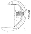
- Figure 2B is a sectional view of the prosthesis shown in Figure 1, illustrating the collet in a non-expanded condition.
- Figure 3 is a sectional view of an alternative prosthesis system, similar to that shown in Figure 2A, but also including an augmentation block.
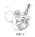
- Figure 4 is an exploded view of the prosthesis shown in Figure 3.
- Figure 5A is a bottom view of a fixation peg useful with the prosthesis shown in Figure 1.
- Figure 5B is a sectional view of the collet shown in Figure 5A.
- Figure 6 is a top view of an augmentation block of the type shown in Figure 4.
- Figure 7 is an isometric view of an alternative modular augmentation and stabilizing prosthesis system according to the present invention.
- Figure 8A is a sectional view of the prosthesis system of Figure 7.
- Figure 8B is a sectional view of the prosthesis system of Figure 7, illustrating the collet in a non-expanded condition.
- Figure 9 is an exploded view of the prosthesis system of Figure 8B.
- Figure 10A is a side view of the collet useful with the invention shown in Figure 7.
- Figure 10B is a bottom view of the collet shown in Figure 10A.
- Figure 10C is a sectional view of the collet shown in Figure 10A.
- Figure 11 is a side view of an expansion pin useful with the invention shown in Figure 7.
- the invention provides a joint prosthesis system 10 that offers enhanced intraoperative versatility and modularity to improve femoral component fixation and stability.
- the invention is particularly applicable to cruciate substituting femoral components.
- the present invention is described with reference to an anticipated use with a femoral component of a knee joint prosthesis. It is understood, however, that the invention can be adapted for use with a variety of joint prostheses.
- a particular advantage of the present invention, which lends itself to use with various types of joint prostheses, is the ease with which fixation elements and augmentation pieces can be secured to a prosthesis.
- FIG. 1 illustrates the prosthesis system 10 of the invention in which a cruciate substituting femoral component 12 has an intercondylar notch 13, anterior and posterior portions 14, 16 and condyles 18, 20. Each condyle includes an inferior articulation surface 22 and an opposed superior bone engaging surface 24.
- Figures 2A and 2B illustrate that the lateral distal flat 30 includes a securement cavity 32, and a similar cavity (not shown) is formed in the medial distal flat 28.
- Fixation pegs 26 are selectively mounted within securement cavities 32 upon the medial and lateral distal flats 28, 30 of superior surface 24, on opposite sides of intercondylar notch 13.
- the system includes modular, selectively mountable fixation pegs 26.
- the fixation pegs 26 are substantially elongate members having a peg body 33 with proximal and distal ends 34, 36.
- a bore 52 extends between the proximal and distal ends of the fixation peg.
- an expansion collet 38 is integral with and is disposed distally of the distal end 36 of peg body 33.
- the system also includes a supply of expansion pins 40 having a proximal end 42, including external threads 44, and a distal, collet expanding end 46.
- the illustrated expansion pins include external threads, it is understood that alternative surface features may exist on the expansion pins, instead of threads, to permit positive engagement with the bore 52 of the fixation peg 26.
- fixation pegs is an important feature of the invention. Since fixation pegs need not be installed on all cruciate sacrificing femoral components, the modularity offered by this invention gives the surgeon the option to attach fixation pegs to a prosthesis to be implanted.
- Fixation pegs can be selectively mounted upon a prosthesis by simply placing the expansion collet end 38 of peg 26 within one of the securement cavities. Thereafter, set screw 40 is inserted within the proximal end 34 of the fixation peg and into bore 52.
- the expansion pin is advanced within the bore and external threads on the screw mate with complementary threads in the bore. Further advancement of the expansion pin causes the distal end of the expansion pin to expand collet 38 so that the collet interferingly engages the walls of cavity 32 to secure the fixation peg to the prosthesis.
- the overall length of the fixation pegs can vary depending upon the anatomical requirements of a patient, the dimensions of prostheses components, and whether the peg is to be used with or without any augmentation block. Generally, the overall length of the peg can be from 2 to 60 millimeters, and m6re preferably from about 10 to 50 millimeters.
- the length of the collet end 38 of peg 26 should be such that it is slightly less than the depth of cavity 32, allowing distal base 48 of peg 26 to rest on superior surface 24 of the femoral component.
- the length of the collet is generally about 2 mm to 20 mm.
- the fixation peg preferably decreases in diameter from distal end 36 to proximal end 34.
- the diameter at base 48 is about 4 mm to 10 mm, while the diameter at proximal end 34 is about 2 mm to 8 mm.
- External surface features 50 such as axial grooves, axial ribs, annular grooves or annular ribs, can be formed in the external surface of the peg to enhance fixation of the prosthesis within bone.
- Figure 5A is a bottom view of fixation pin 26, illustrating the expansion collet 38.
- the collet 38 is preferably slotted, with two perpendicular slots 35 formed therein that separate the collet into four substantially triangular shaped wedges 37.
- an interior portion of collet 38 is angled inwardly to enable the internal geometry of the collet to cooperate with the distal end 46 of expansion pin 40 to cause wedges 37 to expand and to separate from one another when the distal end of the expansion pin is forced into engagement with the corresponding internal surfaces of the wedges.
- the collet may have one or more slots disposed therein.
- Figure 5B is a sectional view of peg 26, showing a bore 52 that extends the length of the body 33 of peg 26.
- Bore 52 preferably includes internal threads 54 that are able to mate with complementary external threads 44 of expansion pin 40.
- bore 52 includes threads 54 in an illustrated embodiment, it is understood that other structures may be formed within bore 52 to facilitate engagement with complementary external structures on expansion pin 40.
- Expansion pins 40 are of a length sufficient to enable them to fit within peg 26 to the extent necessary to expand collet 38.
- the expansion pin includes a proxinal end 42, having external threads 44 that are mateable with internal threads 54 of bore 52, and a distal end 46.
- the proximal end of the expansion pin may include a structure or mechanism, such as a hex head 45, that cooperates with an installation tool to enable it to be advanced into bore 52.
- Distal end 46 preferably has a geometry that will cause expansion of the distal stem of the collet.
- the distal end 46 of pin 40 can include a radius tip 56, a dogged end (not shown) or similar geometries.
- expansion pins 40 are described as being threaded members that threadingly engages internal threads 54 within bore 52,. it is understood that other fixation structures and techniques may be utilized to maintain the expansion pins within the bore 52 and to expand collet 38. As noted above, internal structures may be formed within bore 52 that accommodate complementary surface features on expansion pin 40 to enable mechanical engagement of the components.
- the modular system 10 of the invention may also include an augmentation block 58 that is secured on superior surface 24 of femoral component 12, between the femoral component 12 and the fixation peg 26.
- Augmentation blocks of various designs are well known in the art and are commonly used to facilitate proper seating of prosthesis components within a patient when insufficient bony mass exists in certain areas of the patient's bone upon which the prosthesis is to be mounted.
- the augmentation block 58 illustrated in Figures 3, 4 and 6 is adapted to mount on the superior surface 24, on either the medial or lateral distal flats 28, 30 of a femoral component 12 of an artificial knee joint.
- Block 58 may be adapted for use in either left or right side knee prostheses.
- An augmenting block suitable for a left side prosthesis can mount upon either the medial or lateral inferior condylar surfaces
- an augmenting block suitable for a right side prosthesis can mount upon either the medial or lateral inferior condylar surfaces of the prosthesis.
- block 58 has a first (distal) surface 60 and a second (proximal) surface 62 and an aperture 61 extending between these surfaces.
- a recessed area 63 may surround the aperture 61.
- the area of the proximal surface 62 preferable is greater than the area of the distal surface 60 in order for the block to conform to the geometry of the inner condylar surface of a knee joint femoral component.
- Augmenting block 58 has two opposed, canted surfaces 64, 66 that can be either posterior or anterior surfaces, depending upon whether the augmentation block is mounted on the medial or lateral side, or on a left or right side prosthesis.
- surfaces 64, 66 are canted as such that each surface slopes inwardly from the proximal surface 62 to the distal surface 60 as shown in Figures 4 and 6.
- the angle of the canted surfaces 64, 66 can vary as will be appreciated by those having ordinary skill in the art.
- the angle of surfaces 64, 66 corresponds to the angle of the anterior and posterior chamfers 68, 70 of the femoral component to enable proper seating of the augmenting block 58 within a femoral component.
- Augmenting block 58 further includes surfaces 72, 74 which correspond to either medial or lateral facing surfaces, depending upon whether the augmentation block 58 is used on the lateral or medial side of a prosthesis, or in a left or right side prosthesis.
- Side surfaces 72, 74 preferably are substantially vertical and extend at a right angle to the plane of the proximal or distal surfaces 62, 60.
- augmentation block 58 is adapted to mount on a prosthesis component, such as the medial or lateral distal flats 28, 30, such that the distal surface 60 of block 58 contacts the superior surface 24 of femoral component 12.
- the distal end of expansion collet 38 of fixation peg 26 preferably extends through aperture 61 and beyond the distal surface 60 of block 58 by a distance sufficient to enable collet 38 to fit within a securement cavity 32 disposed in a surface of the femoral component to be augmented.
- the frictional and/or mechanical engagement of the collet with cavity 32 enables the augmentation system to be secured to an appropriate surface of the femoral component.
- distal stem extends beyond the distal surface of the block can vary depending upon the requirements of a given application. Typically, this distance is about 0.155 to 0.175 inch and most preferably about 0.165 inch.- One of ordinary skill in the art will appreciate that the length of the distal stem should not be so great that its distal end contacts the bottom of cavity 32.
- an expansion pin 40 controls the expansion (and, optionally, the contraction) of the distal stem of collet 58.
- the expansion pin is a threaded screw
- tightening of the screw expands the distal stem of the collet
- loosening screw enables a once expanded collet to contract.
- fixation pegs are not permanently installed upon the prosthesis, they can be selectively affixed to the prosthesis at the option of the surgeon.
- the dimensions of the various components of system 10 can vary. It is important, however, that the relative dimensions of the components be such that collet 38, in the non-expanded condition shown in Figure 2B, be able to fit within the securement cavity (and, where applicable through augmentation block aperture 61) without excess friction or interference.
- the outer walls of wedges 37 Upon expansion of the collet, as shown in Figure 2A, the outer walls of wedges 37 should firmly engage the inner walls of securement cavity 32 to prevent dislodgement or movement of the fixation peg.
- the preferred tensile attachment force of the collet to the prosthesis should be in the range of about 50 to 500 kg.
- the dimensions of these components will vary depending upon the requirements of a given application, and one of ordinary skill in the art can readily determine the appropriate relative dimensions.
- the diameter of the collet in the non-expanded condition is approximateiy 0.240 to 0.260 inch, and preferably it is about 0.250 inch.
- the diameter of the collet in the expanded condition preferably is about 0.010 to 0.020 inch greater than the diameter in the non-expanded condition.
- the diameter of the securement cavity 32 is sufficient to yield a secure interference fit between the collet and the cavity when the collet is expanded.
- the cavity has a diameter of about 0.26 inch ⁇ 0.10 inch.
- the depth of the mounting cavity can vary, as will be understood by those of ordinary skill in the art, but preferably the depth is about 0.18 to 0.26 inch.
- the collet 38 should not engage the bottom wall of cavity 32.
- FIG. 7 through 11 Another embodiment, illustrated in Figures 7 through 11, provides an alternative fixation technique for the modular prosthesis system 100 of the invention.
- the collet is not integral with the fixation peg, but the same modular fixation options exist. That is, fixation pegs can be mounted directly upon the superior surface of a joint prothesis, without an augmentation block, or an augmentation block can be disposed between the fixation peg and the prosthesis.
- Figure 7 illustrates a cruciate substituting femoral component 102 that includes an intercondylar notch 104, an inferior surface 106 having condyles 108, 110 and a superior bone engaging surface 112 having lateral and medial distal flats.
- the prosthesis depicted in Figure 7 is assumed to be a left knee femoral component having anterior 118 and posterior 120 surfaces.
- Figure 7 illustrates an augmentation block 122 and fixation peg 124 mounted on lateral distal flat 116. It is understood that the fixation peg 124 can be mounted directly upon the medial or lateral distal flats without an augmentation block.
- Figures 8A through 11 illustrate the various components of system 100. These components include fixation pegs 124, one or more optional augmentation blocks 122, one or more collets 126 and one or more expansion pins 128. Further, as noted above with respect to Figures 1 through 6, the femoral component 102 includes at least one securement cavity 130. Preferably, one securement cavity is mounted on each of the medial and lateral distal flats of the femoral component.
- Fixation peg 124 is an elongate member having proximal and distal ends 132, 134.
- the distal end 134 of the peg includes a base 136 which surrounds an opening 138 of an internal bore 140 which extends within the peg.
- Internal threads 141 (or other internal fixation structures) preferably are present within the bore and may extend the entire length of the bore or, alternatively, threads be present only in selected regions of the bore.
- the proximal end 132 of peg 126 is shown to include a closed top 142, the top may alternatively be open.
- the base 136 abuts the proximal surface 144 of augmentation block 122. Alternatively, if no augmentation block is used, base 136 will abut the superior surface 112 of femoral component 102.
- Fixation peg 124 is of a construction similar to that described above with respect to Figures 1 through 6, except that it does not include an integral distal collet. Fixation peg 124 thus may include external surface features 146 and may have a larger diameter at distal end 134 than at proximal end 132.
- expansion pin 128 is an elongate member that has distal 148 and proximal 150 ends.
- the expansion pin is intended to expand collet 128, by action of its distal end 148, while its proximal end 150 engages both a proximal end 152 of the collet and the fixation peg.
- various structures can enable the expansion pin to expand the collet and to engage the collet and the fixation peg, a preferred embodiment is described below.
- the proximal end 150 of the expansion pin 128 preferably includes external threads 154.
- the threads 154 extend over a distance of about 2 to 20 mm.
- the distal end 148 of the collet is non-threaded and preferably has a diameter that is slightly less than the diameter of proximal end 150.
- the distal tip 153 of expansion pin 128 has a geometry that will cause expansion of the collet, such as a radius tip point 155, a dogged end (not shown), or similar geometries.
- the head 151 of the expansion pin 128 is a hex head.
- Collet 126 has a proximal end of 152, including collar 156 and a distal, collet expanding end 158.
- the collar 156 can mount within a recessed area surrounding cavity 130.
- the collar 156 will be seated in a recessed area 159 surrounding aperture 160 on a proximal surface 144 of block 122.
- the collar 156 and the recessed area can be of virtually any corresponding shapes including, for example, circular and D-shaped.
- a D-shaped collar which includes a flat end 169, or another irregularly shaped collar, can be useful to prevent any unwanted rotation of the collet within the securement cavity 130 or aperture 160.
- collet 126 preferably includes internal threads 164 within proximal region 152. These threads are complementary to threads 154 of expansion pin 128 such that a lower (distal) portion of threads 154 mate with threads 164 to maintain the expansion pin in a desired position with the collet.
- the distal end of the collet is preferably slotted and is of a structure as described above for collet 38 illustrated in Figures 1 through 6.
- Figures 7 through 9 illustrate an augmentation block 122 used with system 100. It is understood that the use of augmentation block 122 is optional. If the augmentation block 122 is not to be used, the fixation peg 124 is mounted directly to the superior surface 112 of femoral component 102.
- System 100 can be utilized as follows. If a surgeon determines that it is desirable to mount fixation pegs 124 upon prosthesis 102, set screw 128 is advanced within collet, without expanding the collet, until threads 154 and 164 mate. The collet is then positioned within securement cavity 130 and the set screw is tightened until the collet expands to the extent that it maintains good purchase upon the inner walls of the securement cavity 130. The torque needed to effect such expansion generally is about 20 to 40 inch-pounds, and more preferably about 30 inch-pounds. Thereafter, the fixation peg is threaded upon expansion pin 128 such that threads 154 mate with internal threads 141 of fixation peg 124. Prcferably the length of the external threads 154 that remain exposed once the expansion pin is deployed to expand the collet is about 6 to 12 mm.
- a similar procedure is utilized for an embodiment in which an augmentation block 122 is to be used.
- collet 126 may be predisposed within aperture 160 of augmentation block 122.
- expansion pin 128 is advanced within the collet causing the collet to expand and to secure the augmentation block to the femoral component.
- the fixation peg can be threaded upon the proximal end of the expansion pin.
- system 100 include internal threads within the collet 126 and fixation peg 124, and external threads on expansion pin 128. It is understood that other structures can be used, instead of threads, to facilitate joinder of the set screw to both the collet and the fixation peg.
- the prostheses components of the invention can be made from a variety of biocompatible materials having high strength, durability and resistance to wear debris.
- materials include metal alloys such as a cobalt chromium alloys, titanium alloys, stainless steel, ceramics and other materials, including polymers, that are well known for use in the manufacture of implantable bone prostheses.
- a preferred material for the prostheses components is a cobalt chromium alloy such as ASTM F-75.
- the collet components preferably are made from a malleable metal or metal alloy to reduce the risk of tensile failure as a result of collet expansion. Where such materials are used to form a threaded component, the materials should be able to deform (but not fail) when subjected to a torque of about 20 to 65 in-lbs, and more preferably about 25-35 in-lbs.
- a preferred material is a wrought cobalt chromium alloy such as ASTM F-90.
- the set screw preferably is made from a metal or metal alloy that has a higher modulus and a greater hardness than does the collet. Such properties ensure that the collet (and not the expansion pin) will deform when subjected to torque and/or axial load.
- a preferred material from which the expansion pin can be manufactured is wrought cobalt chromium alloy such as ASTM F-1537 (formerly known as ASTM F-799).
- the tensile securement values of the fixation pegs and/or augmentation blocks to the femoral components preferably are in the range of about 50 to 500 kg. This secure fit ensures that the performance of the prosthesis component is not compromised.
- the modular fixation peg and augmentation system of the invention can be easily attached within a femoral component of a knee joint prosthesis.
Abstract
Description
Claims (13)
- A modular knee joint prosthesis system, comprising a femoral component having a superior bone engaging surface and an inferior articulation surface, the superior surface including at least one securement cavity, each of the securement cavities being defined by a sidewall and a bottom wall;at least one substantially elongate fixation peg member, each fixation peg member being selectively matable, via a collet member, with one of the securement cavities of the superior surface of the femoral component, each fixation peg member having a distal end, a proximal bone engaging end and an internal bore;at least one collet member matable with a distal end of the fixation peg member, each collet member having an expandable distal end adapted to fit within and selectively engage the sidewall of one of the securement cavities and a proximal end including an internal bore; andan expansion pin element having a proximal end including an external structure matable with the internal bore of the fixation peg member and the internal bore of the collet member, and a distal end capable of selectively expanding the collet such that the collet engages the sidewalls of the securement cavity.
- The system of claim 1 wherein the internal bore of the fixation peg member includes an internally threaded portion.
- The system of claim 2 wherein the internal bore of the collet member includes an internally threaded portion.
- The system of claim 3 wherein the external structure of the expansion pin element comprises an external threaded region.
- The system of claim 1 wherein the collet member is integral with the elongate fixation pegs and forms a distal end thereof.
- The system of claim 4 wherein the collet member is separate from the fixation peg member, and wherein the collet member includesan expandable distal end formed by two or more expandable wedge-like members each separated by a slot; anda collar at a proximal end thereof.
- The system of claim 6 wherein the collar of the collet member seats upon the securement cavity with the distal end of the collet member extending therein such that the expansion pin element is threadingly engaged within the internally threaded region of the axial bore of the collet member and the internally threaded region of the fixation peg member.
- The system of claim 7 further comprising at least one augmentation block having first and second opposed surfaces and an aperture extending therebetween, the first surface being mountable upon a portion of the superior surface of the femoral component and the aperture being dimensioned to receive the distal end of the collet member such that the augmentation block and the fixation peg member are together selectively matable with the articulation component.
- The system of claim 8 wherein the articulation component is a femoral component of a knee joint prosthesis.
- The system of claim 8 wherein in the femoral component is a cruciate substituting femoral component including an intercondylar notch formed on the superior surface thereof.
- The system of claim 10 wherein one of the securement cavities is formed on each of a medial distal flat and a lateral distal flat of the femoral component.
- The system of claim 6 wherein the fixation peg members decrease in diameter from an end adjacent one of the superior surface of the augmentation block and the superior surface of the articulation component to the proximal end thereof.
- A modular joint prosthesis system, comprising:an articulation component having a first, bone engaging surface and a second, articulation surface, the first surface including at least one securement cavity, each of the securement cavities being defined by a sidewall and a bottom wall;at least one substantially elongate fixation peg member, each fixation peg member being selectively matable within one of the securement cavities on the first surface of the articulation component and each fixation peg member having a distal end including an expandable collet that is engageable with the circular sidewall of one of the securement cavities, a proximal bone engaging end and an axial bore extending between the distal and proximal ends of the fixation peg member; andan expansion pin element having a proximal end including at least one external structure matable within the axial bore of the fixation peg member, the expansion pin element further including a distal end capable of selectively expanding the collet such that the collet engages the sidewalls of the securement cavity.
Applications Claiming Priority (2)
| Application Number | Priority Date | Filing Date | Title |
|---|---|---|---|
| US08/772,966 US5766255A (en) | 1996-12-23 | 1996-12-23 | Modular joint prosthesis stabilization and augmentation system |
| US772966 | 1996-12-23 |
Publications (3)
| Publication Number | Publication Date |
|---|---|
| EP0850606A2 true EP0850606A2 (en) | 1998-07-01 |
| EP0850606A3 EP0850606A3 (en) | 1998-12-16 |
| EP0850606B1 EP0850606B1 (en) | 2004-05-12 |
Family
ID=25096756
Family Applications (1)
| Application Number | Title | Priority Date | Filing Date |
|---|---|---|---|
| EP97310443A Expired - Lifetime EP0850606B1 (en) | 1996-12-23 | 1997-12-22 | Modular joint prosthesis stabilization and augmentation system |
Country Status (5)
| Country | Link |
|---|---|
| US (1) | US5766255A (en) |
| EP (1) | EP0850606B1 (en) |
| JP (1) | JPH10309296A (en) |
| CA (1) | CA2225322A1 (en) |
| DE (1) | DE69729058T2 (en) |
Cited By (13)
| Publication number | Priority date | Publication date | Assignee | Title |
|---|---|---|---|---|
| FR2780636A1 (en) * | 1998-07-06 | 2000-01-07 | Merck Biomaterial France | Modular knee prosthesis comprises lower femoral mounting plate and upper tibial plate for total knee prosthesis |
| EP1550418A1 (en) * | 2003-12-30 | 2005-07-06 | Zimmer Technology, Inc. | Implant systems with fastener for mounting on an articulation surface of an orthopedic joint |
| US7462199B2 (en) | 2003-12-30 | 2008-12-09 | Medicinelodge, Inc. | Methods for mounting a tibial condylar implant |
| ES2315044A1 (en) * | 2002-05-24 | 2009-03-16 | Medicinalodge, Inc | Modular femoral components for knee arthroplasty |
| US7578824B2 (en) | 2003-12-30 | 2009-08-25 | Zimmer, Inc. | Methods and apparatus for forming a tunnel through a proximal end of a tibia |
| US7766969B2 (en) | 2005-12-05 | 2010-08-03 | Zimmer, Inc. | Modular progressive implant for a joint articulation surface |
| US7819878B2 (en) | 2003-12-30 | 2010-10-26 | Zimmer, Inc. | Tibial condylar hemiplasty tissue preparation instruments and methods |
| US7867280B2 (en) | 2003-12-30 | 2011-01-11 | Zimmer, Inc. | Methods for mounting and using tethered joint bearing implants |
| US7922772B2 (en) | 2002-05-24 | 2011-04-12 | Zimmer, Inc. | Implants and related methods and apparatus for securing an implant on an articulating surface of an orthopedic joint |
| US8048163B2 (en) | 2002-02-20 | 2011-11-01 | Zimmer, Inc. | Knee arthroplasty prosthesis |
| EP2682073A1 (en) * | 2012-07-02 | 2014-01-08 | DePuy (Ireland) | Knee prosthesis system with side-mounted augments |
| WO2018095778A3 (en) * | 2016-11-24 | 2018-09-27 | Waldemar Link Gmbh & Co. Kg | Intermediate segment for a joint component |
| US10966837B2 (en) | 2009-12-21 | 2021-04-06 | Derek James Wallace McMinn | Cup with conical permanent pegs |
Families Citing this family (51)
| Publication number | Priority date | Publication date | Assignee | Title |
|---|---|---|---|---|
| US6676704B1 (en) | 1994-08-12 | 2004-01-13 | Diamicron, Inc. | Prosthetic joint component having at least one sintered polycrystalline diamond compact articulation surface and substrate surface topographical features in said polycrystalline diamond compact |
| US6793681B1 (en) | 1994-08-12 | 2004-09-21 | Diamicron, Inc. | Prosthetic hip joint having a polycrystalline diamond articulation surface and a plurality of substrate layers |
| US6290726B1 (en) | 2000-01-30 | 2001-09-18 | Diamicron, Inc. | Prosthetic hip joint having sintered polycrystalline diamond compact articulation surfaces |
| US6494918B1 (en) | 2000-01-30 | 2002-12-17 | Diamicron, Inc. | Component for a prosthetic joint having a diamond load bearing and articulation surface |
| US6402787B1 (en) | 2000-01-30 | 2002-06-11 | Bill J. Pope | Prosthetic hip joint having at least one sintered polycrystalline diamond compact articulation surface and substrate surface topographical features in said polycrystalline diamond compact |
| US6596225B1 (en) | 2000-01-31 | 2003-07-22 | Diamicron, Inc. | Methods for manufacturing a diamond prosthetic joint component |
| US6425922B1 (en) | 2000-01-30 | 2002-07-30 | Diamicron, Inc. | Prosthetic hip joint having at least one sintered polycrystalline diamond compact articulation surface |
| US6514289B1 (en) | 2000-01-30 | 2003-02-04 | Diamicron, Inc. | Diamond articulation surface for use in a prosthetic joint |
| US6074424A (en) * | 1998-01-23 | 2000-06-13 | Sulzer Orthopedics Inc. | Implantable knee joint prosthesis convertible from primary to revision |
| US6086614A (en) * | 1998-01-23 | 2000-07-11 | Sulzer Orthopedics Inc. | Orthopedic prosthesis having anti-backout screw |
| US6071311A (en) * | 1998-08-14 | 2000-06-06 | Johnson & Johnson Professional, Inc. | Cylindrical box femoral stem |
| US20050203630A1 (en) * | 2000-01-30 | 2005-09-15 | Pope Bill J. | Prosthetic knee joint having at least one diamond articulation surface |
| US6709463B1 (en) | 2000-01-30 | 2004-03-23 | Diamicron, Inc. | Prosthetic joint component having at least one solid polycrystalline diamond component |
| US6410877B1 (en) | 2000-01-30 | 2002-06-25 | Diamicron, Inc. | Methods for shaping and finishing prosthetic joint components including polycrystalline diamond compacts |
| US8114163B2 (en) | 2000-04-10 | 2012-02-14 | Biomet Manufacturing Corp. | Method and apparatus for adjusting height and angle for a radial head |
| US8920509B2 (en) | 2000-04-10 | 2014-12-30 | Biomet Manufacturing, Llc | Modular radial head prosthesis |
| US8535382B2 (en) | 2000-04-10 | 2013-09-17 | Biomet Manufacturing, Llc | Modular radial head prostheses |
| WO2002007647A2 (en) * | 2000-07-20 | 2002-01-31 | Depuy Orthopaedics, Inc. | Modular connection for orthopedic component |
| EP1301147B1 (en) * | 2000-07-20 | 2009-01-21 | Depuy Orthopaedics, Inc. | Modular femoral stem component for a hip joint prosthesis |
| US6482209B1 (en) * | 2001-06-14 | 2002-11-19 | Gerard A. Engh | Apparatus and method for sculpting the surface of a joint |
| US7615081B2 (en) * | 2002-05-24 | 2009-11-10 | Zimmer, Inc. | Femoral components for knee arthroplasty |
| US7150761B2 (en) * | 2002-05-24 | 2006-12-19 | Medicinelodge, Inc. | Modular femoral components for knee arthroplasty |
| AU2003287190A1 (en) | 2002-10-23 | 2004-05-13 | Alastair J. T. Clemow | Modular femoral component for a total knee joint replacement for minimally invasive implantation |
| US20040102852A1 (en) | 2002-11-22 | 2004-05-27 | Johnson Erin M. | Modular knee prosthesis |
| US7722644B2 (en) | 2003-06-11 | 2010-05-25 | Medicine Lodge, Inc. | Compact line locks and methods |
| US7727281B2 (en) * | 2003-12-08 | 2010-06-01 | Ortho Development Corporation | Modular femoral knee stem extender |
| WO2005067521A2 (en) * | 2004-01-12 | 2005-07-28 | Depuy Products, Inc. | Systems and methods for compartmental replacement in a knee |
| US7544209B2 (en) * | 2004-01-12 | 2009-06-09 | Lotke Paul A | Patello-femoral prosthesis |
| US8002840B2 (en) | 2004-01-12 | 2011-08-23 | Depuy Products, Inc. | Systems and methods for compartmental replacement in a knee |
| US8535383B2 (en) * | 2004-01-12 | 2013-09-17 | DePuy Synthes Products, LLC | Systems and methods for compartmental replacement in a knee |
| US8852195B2 (en) * | 2004-07-09 | 2014-10-07 | Zimmer, Inc. | Guide templates for surgical implants and related methods |
| US7488347B1 (en) | 2005-01-06 | 2009-02-10 | Medicine Lodge, Inc. | Transosseous graft retention system and method |
| US7641694B1 (en) | 2005-01-06 | 2010-01-05 | IMDS, Inc. | Line lock graft retention system and method |
| US7998217B1 (en) | 2005-02-02 | 2011-08-16 | Biomet Manufacturing Corp. | Modular offset stem implants |
| US7842093B2 (en) * | 2006-07-18 | 2010-11-30 | Biomet Manufacturing Corp. | Method and apparatus for a knee implant |
| US8187280B2 (en) | 2007-10-10 | 2012-05-29 | Biomet Manufacturing Corp. | Knee joint prosthesis system and method for implantation |
| US8562616B2 (en) | 2007-10-10 | 2013-10-22 | Biomet Manufacturing, Llc | Knee joint prosthesis system and method for implantation |
| US8157869B2 (en) * | 2007-01-10 | 2012-04-17 | Biomet Manufacturing Corp. | Knee joint prosthesis system and method for implantation |
| US8163028B2 (en) | 2007-01-10 | 2012-04-24 | Biomet Manufacturing Corp. | Knee joint prosthesis system and method for implantation |
| US8328873B2 (en) | 2007-01-10 | 2012-12-11 | Biomet Manufacturing Corp. | Knee joint prosthesis system and method for implantation |
| JP5156093B2 (en) * | 2008-05-30 | 2013-03-06 | 日本写真印刷株式会社 | Electronic device and method for mounting protection panel with touch input function |
| WO2009154781A1 (en) * | 2008-06-20 | 2009-12-23 | Yale University | Porous expansion bolt |
| EP2603173B1 (en) * | 2010-08-12 | 2016-03-23 | Smith & Nephew, Inc. | Structures for use in orthopaedic implant fixation |
| JP5883131B2 (en) * | 2011-07-07 | 2016-03-09 | ジンマー,インコーポレイティド | Method and apparatus for strengthening the posterior side of a femoral knee prosthesis element |
| US9414927B2 (en) | 2011-12-08 | 2016-08-16 | Imds Llc | Shoulder arthroplasty |
| US9439768B2 (en) | 2011-12-08 | 2016-09-13 | Imds Llc | Glenoid vault fixation |
| US9788957B2 (en) | 2012-12-07 | 2017-10-17 | Cleveland Clinic Foundation | Glenoid vault fixation |
| US10130480B2 (en) | 2013-03-13 | 2018-11-20 | Howmedica Osteonics Corp. | Modular patella trials |
| US11065124B2 (en) | 2018-05-25 | 2021-07-20 | Howmedica Osteonics Corp. | Variable thickness femoral augments |
| US11083585B2 (en) | 2019-05-09 | 2021-08-10 | Howmedica Osteonics Corp. | Spring retained femoral augment |
| US11491013B2 (en) * | 2019-07-11 | 2022-11-08 | Howmedica Osteonics Corp. | Augment and means for connecting the same to a joint prosthesis |
Citations (1)
| Publication number | Priority date | Publication date | Assignee | Title |
|---|---|---|---|---|
| US4936847A (en) | 1988-12-27 | 1990-06-26 | Johnson & Johnson Orthopaedics, Inc. | Revision knee prosthesis |
Family Cites Families (37)
| Publication number | Priority date | Publication date | Assignee | Title |
|---|---|---|---|---|
| US1664566A (en) * | 1924-08-25 | 1928-04-03 | Briggs Mfg Co | Fastener |
| US1816970A (en) * | 1929-03-11 | 1931-08-04 | Hess Gottfried | Anchor socket |
| US2490364A (en) * | 1948-02-27 | 1949-12-06 | Herman H Livingston | Bone pin |
| US2616328A (en) * | 1951-02-01 | 1952-11-04 | William F Mathias Jr | Fastener |
| US3076453A (en) * | 1961-01-16 | 1963-02-05 | Raymond G Tronzo | Hip nail |
| US4081866A (en) * | 1977-02-02 | 1978-04-04 | Howmedica, Inc. | Total anatomical knee prosthesis |
| US4209861A (en) * | 1978-02-22 | 1980-07-01 | Howmedica, Inc. | Joint prosthesis |
| US4312614A (en) * | 1978-11-21 | 1982-01-26 | Itw Limited | Security fastener |
| US4353135A (en) * | 1980-05-09 | 1982-10-12 | Minnesota Mining And Manufacturing Company | Patellar flange and femoral knee-joint prosthesis |
| US4711232A (en) * | 1985-07-12 | 1987-12-08 | Artur Fischer | Bone fastener and method of installing same |
| CH667383A5 (en) * | 1985-09-12 | 1988-10-14 | Sulzer Ag | TIBIAL PART FOR A KNEE JOINT PROSTHESIS. |
| US4822366A (en) * | 1986-10-16 | 1989-04-18 | Boehringer Mannheim Corporation | Modular knee prosthesis |
| US4731086A (en) * | 1987-04-20 | 1988-03-15 | Dow Corning Wright | Shim for femoral knee joint prosthesis and method of using |
| FR2615726A1 (en) * | 1987-06-01 | 1988-12-02 | Landos Applic Orthopediques Fs | Prosthetic fixation element with anchoring stud |
| GB2211261B (en) * | 1987-10-19 | 1991-03-27 | Nifco Inc | Coupler for coupling together plates |
| US4892547A (en) * | 1988-02-03 | 1990-01-09 | Biomet, Inc. | Partially stabilized knee prosthesis |
| US4950298A (en) * | 1988-04-08 | 1990-08-21 | Gustilo Ramon B | Modular knee joint prosthesis |
| GB2223174A (en) * | 1988-09-08 | 1990-04-04 | Bristol Myers Co | Prosthetic implant |
| CA2006152C (en) * | 1988-12-27 | 1999-03-23 | John Edward Slamin | Modular knee prosthesis |
| US5207711A (en) * | 1990-01-08 | 1993-05-04 | Caspari Richard B | Knee joint prosthesis |
| US5201768A (en) * | 1990-01-08 | 1993-04-13 | Caspari Richard B | Prosthesis for implant on the tibial plateau of the knee |
| US5092897A (en) * | 1990-03-15 | 1992-03-03 | Forte Mark R | Implantable acetabular prosthetic hip joint with universal adjustability |
| US4971500A (en) * | 1990-03-19 | 1990-11-20 | Illinois Tool Works Inc. | Enclosed plastic screw grommet |
| DE69130681T2 (en) * | 1990-09-25 | 1999-06-10 | Innovasive Devices Inc | BONE FIXING DEVICE |
| AU9089891A (en) * | 1990-11-14 | 1992-06-11 | Arch Development Corporation | Improved floating bearing prosthetic knee |
| US5108446A (en) * | 1990-11-26 | 1992-04-28 | Sulzer Brothers Limited | Hip joint prosthesis |
| DE69123966T2 (en) * | 1991-10-11 | 1997-07-10 | Essor Soc Civ | Surgical prosthesis for the knee joint |
| FR2684290B1 (en) * | 1991-11-29 | 1994-01-21 | Tornier Ets | KNEE PROSTHESIS. |
| US5176684A (en) * | 1992-02-20 | 1993-01-05 | Dow Corning Wright | Modular shaping and trial reduction guide for implantation of posterior-stabilized femoral prosthesis and method of using same |
| US5370693A (en) * | 1992-09-28 | 1994-12-06 | Depuy Inc. | Orthopedic implant augmentation and stabilization device |
| US5549687A (en) * | 1992-12-10 | 1996-08-27 | Wright Medical Technology, Inc. | Retrofit posterior stabilizing housing implant for replacement knee prosthesis |
| FR2702368B1 (en) * | 1993-03-10 | 1995-06-09 | Medinov Sa | Tibial implant for knee prosthesis. |
| US5405395A (en) * | 1993-05-03 | 1995-04-11 | Wright Medical Technology, Inc. | Modular femoral implant |
| US5549685A (en) * | 1994-02-23 | 1996-08-27 | Zimmer, Inc. | Augmentation for an orthopaedic implant |
| EP0797417B1 (en) * | 1994-10-28 | 2000-01-05 | Sulzer Orthopedics Inc. | Knee prosthesis with shims |
| US5556433A (en) * | 1994-12-01 | 1996-09-17 | Johnson & Johnson Professional, Inc. | Modular knee prosthesis |
| US5984969A (en) * | 1995-06-01 | 1999-11-16 | Johnson & Johnson Professional, Inc. | Joint prosthesis augmentation system |
-
1996
- 1996-12-23 US US08/772,966 patent/US5766255A/en not_active Expired - Lifetime
-
1997
- 1997-12-19 CA CA002225322A patent/CA2225322A1/en not_active Abandoned
- 1997-12-22 JP JP9370177A patent/JPH10309296A/en active Pending
- 1997-12-22 DE DE69729058T patent/DE69729058T2/en not_active Expired - Lifetime
- 1997-12-22 EP EP97310443A patent/EP0850606B1/en not_active Expired - Lifetime
Patent Citations (1)
| Publication number | Priority date | Publication date | Assignee | Title |
|---|---|---|---|---|
| US4936847A (en) | 1988-12-27 | 1990-06-26 | Johnson & Johnson Orthopaedics, Inc. | Revision knee prosthesis |
Cited By (18)
| Publication number | Priority date | Publication date | Assignee | Title |
|---|---|---|---|---|
| FR2780636A1 (en) * | 1998-07-06 | 2000-01-07 | Merck Biomaterial France | Modular knee prosthesis comprises lower femoral mounting plate and upper tibial plate for total knee prosthesis |
| US9072605B2 (en) | 2002-02-20 | 2015-07-07 | Zimmer, Inc. | Knee arthroplasty prosthesis |
| US8048163B2 (en) | 2002-02-20 | 2011-11-01 | Zimmer, Inc. | Knee arthroplasty prosthesis |
| ES2315044A1 (en) * | 2002-05-24 | 2009-03-16 | Medicinalodge, Inc | Modular femoral components for knee arthroplasty |
| US7922772B2 (en) | 2002-05-24 | 2011-04-12 | Zimmer, Inc. | Implants and related methods and apparatus for securing an implant on an articulating surface of an orthopedic joint |
| US7867280B2 (en) | 2003-12-30 | 2011-01-11 | Zimmer, Inc. | Methods for mounting and using tethered joint bearing implants |
| US7771483B2 (en) | 2003-12-30 | 2010-08-10 | Zimmer, Inc. | Tibial condylar hemiplasty implants, anchor assemblies, and related methods |
| US7819878B2 (en) | 2003-12-30 | 2010-10-26 | Zimmer, Inc. | Tibial condylar hemiplasty tissue preparation instruments and methods |
| US7867236B2 (en) | 2003-12-30 | 2011-01-11 | Zimmer, Inc. | Instruments and methods for preparing a joint articulation surface for an implant |
| US7578824B2 (en) | 2003-12-30 | 2009-08-25 | Zimmer, Inc. | Methods and apparatus for forming a tunnel through a proximal end of a tibia |
| US7462199B2 (en) | 2003-12-30 | 2008-12-09 | Medicinelodge, Inc. | Methods for mounting a tibial condylar implant |
| US8236060B2 (en) | 2003-12-30 | 2012-08-07 | Zimmer, Inc. | Tethered joint bearing implants and systems |
| EP1550418A1 (en) * | 2003-12-30 | 2005-07-06 | Zimmer Technology, Inc. | Implant systems with fastener for mounting on an articulation surface of an orthopedic joint |
| US7766969B2 (en) | 2005-12-05 | 2010-08-03 | Zimmer, Inc. | Modular progressive implant for a joint articulation surface |
| US10966837B2 (en) | 2009-12-21 | 2021-04-06 | Derek James Wallace McMinn | Cup with conical permanent pegs |
| EP2682073A1 (en) * | 2012-07-02 | 2014-01-08 | DePuy (Ireland) | Knee prosthesis system with side-mounted augments |
| WO2018095778A3 (en) * | 2016-11-24 | 2018-09-27 | Waldemar Link Gmbh & Co. Kg | Intermediate segment for a joint component |
| US11583404B2 (en) | 2016-11-24 | 2023-02-21 | Waldemar Link Gmbh & Co. Kg | Intermediate segment for a joint component |
Also Published As
| Publication number | Publication date |
|---|---|
| EP0850606A3 (en) | 1998-12-16 |
| EP0850606B1 (en) | 2004-05-12 |
| US5766255A (en) | 1998-06-16 |
| DE69729058T2 (en) | 2005-05-12 |
| DE69729058D1 (en) | 2004-06-17 |
| JPH10309296A (en) | 1998-11-24 |
| CA2225322A1 (en) | 1998-06-23 |
Similar Documents
| Publication | Publication Date | Title |
|---|---|---|
| US5766255A (en) | Modular joint prosthesis stabilization and augmentation system | |
| US5755800A (en) | Modular joint prosthesis augmentation system | |
| CA2177742C (en) | Augmentation device for joint prosthesis | |
| US5405398A (en) | Prosthetic knee with posterior stabilized femoral component | |
| EP0904749B1 (en) | Joint prosthesis having controlled rotation | |
| US5658344A (en) | Tibial insert reinforcement pin | |
| EP0904750B1 (en) | Rotatable joint prosthesis with axial securement | |
| US5571194A (en) | Femoral augmentation system for artificial knee joint | |
| EP0797417B1 (en) | Knee prosthesis with shims | |
| US6709461B2 (en) | Modular joint prosthesis system | |
| CA2367652C (en) | Constrained prosthetic knee with rotating bearing | |
| EP1023881B1 (en) | Modular tibial insert for prosthesis system | |
| US6139581A (en) | Posterior compensation tibial tray | |
| US5019103A (en) | Tibial wedge system | |
| US6773461B2 (en) | Constrained prosthetic knee with rotating bearing | |
| EP0986994B1 (en) | Tapped box femoral stem attachment for a modular knee prosthesis | |
| US20120330430A1 (en) | Constrained prosthetic knee with rotating bearing | |
| AU5295799A (en) | Joint prosthesis and anchoring means | |
| EP0387308A1 (en) | Knee-joint prosthesis. |
Legal Events
| Date | Code | Title | Description |
|---|---|---|---|
| PUAI | Public reference made under article 153(3) epc to a published international application that has entered the european phase |
Free format text: ORIGINAL CODE: 0009012 |
|
| AK | Designated contracting states |
Kind code of ref document: A2 Designated state(s): DE FR GB |
|
| AX | Request for extension of the european patent |
Free format text: AL;LT;LV;MK;RO;SI |
|
| PUAL | Search report despatched |
Free format text: ORIGINAL CODE: 0009013 |
|
| AK | Designated contracting states |
Kind code of ref document: A3 Designated state(s): AT BE CH DE DK ES FI FR GB GR IE IT LI LU MC NL PT SE |
|
| AX | Request for extension of the european patent |
Free format text: AL;LT;LV;MK;RO;SI |
|
| 17P | Request for examination filed |
Effective date: 19990527 |
|
| AKX | Designation fees paid |
Free format text: DE FR GB |
|
| 17Q | First examination report despatched |
Effective date: 20020327 |
|
| RAP1 | Party data changed (applicant data changed or rights of an application transferred) |
Owner name: DEPUY PRODUCTS, INC. |
|
| RAP1 | Party data changed (applicant data changed or rights of an application transferred) |
Owner name: DEPUY PRODUCTS, INC. |
|
| GRAP | Despatch of communication of intention to grant a patent |
Free format text: ORIGINAL CODE: EPIDOSNIGR1 |
|
| GRAS | Grant fee paid |
Free format text: ORIGINAL CODE: EPIDOSNIGR3 |
|
| GRAA | (expected) grant |
Free format text: ORIGINAL CODE: 0009210 |
|
| AK | Designated contracting states |
Kind code of ref document: B1 Designated state(s): DE FR GB |
|
| PG25 | Lapsed in a contracting state [announced via postgrant information from national office to epo] |
Ref country code: FR Free format text: LAPSE BECAUSE OF FAILURE TO SUBMIT A TRANSLATION OF THE DESCRIPTION OR TO PAY THE FEE WITHIN THE PRESCRIBED TIME-LIMIT Effective date: 20040512 |
|
| REG | Reference to a national code |
Ref country code: GB Ref legal event code: FG4D |
|
| REF | Corresponds to: |
Ref document number: 69729058 Country of ref document: DE Date of ref document: 20040617 Kind code of ref document: P |
|
| PLBE | No opposition filed within time limit |
Free format text: ORIGINAL CODE: 0009261 |
|
| STAA | Information on the status of an ep patent application or granted ep patent |
Free format text: STATUS: NO OPPOSITION FILED WITHIN TIME LIMIT |
|
| 26N | No opposition filed |
Effective date: 20050215 |
|
| EN | Fr: translation not filed | ||
| PGFP | Annual fee paid to national office [announced via postgrant information from national office to epo] |
Ref country code: GB Payment date: 20161221 Year of fee payment: 20 Ref country code: DE Payment date: 20161213 Year of fee payment: 20 |
|
| REG | Reference to a national code |
Ref country code: DE Ref legal event code: R071 Ref document number: 69729058 Country of ref document: DE |
|
| REG | Reference to a national code |
Ref country code: GB Ref legal event code: PE20 Expiry date: 20171221 |
|
| PG25 | Lapsed in a contracting state [announced via postgrant information from national office to epo] |
Ref country code: GB Free format text: LAPSE BECAUSE OF EXPIRATION OF PROTECTION Effective date: 20171221 |