EP0850672A2 - LCD game machine and ROM cartridge - Google Patents
LCD game machine and ROM cartridge Download PDFInfo
- Publication number
- EP0850672A2 EP0850672A2 EP97122952A EP97122952A EP0850672A2 EP 0850672 A2 EP0850672 A2 EP 0850672A2 EP 97122952 A EP97122952 A EP 97122952A EP 97122952 A EP97122952 A EP 97122952A EP 0850672 A2 EP0850672 A2 EP 0850672A2
- Authority
- EP
- European Patent Office
- Prior art keywords
- key
- game
- display portion
- operative
- game machine
- Prior art date
- Legal status (The legal status is an assumption and is not a legal conclusion. Google has not performed a legal analysis and makes no representation as to the accuracy of the status listed.)
- Granted
Links
Images


Classifications
-
- A63F13/06—
-
- A—HUMAN NECESSITIES
- A63—SPORTS; GAMES; AMUSEMENTS
- A63F—CARD, BOARD, OR ROULETTE GAMES; INDOOR GAMES USING SMALL MOVING PLAYING BODIES; VIDEO GAMES; GAMES NOT OTHERWISE PROVIDED FOR
- A63F13/00—Video games, i.e. games using an electronically generated display having two or more dimensions
- A63F13/90—Constructional details or arrangements of video game devices not provided for in groups A63F13/20 or A63F13/25, e.g. housing, wiring, connections or cabinets
- A63F13/92—Video game devices specially adapted to be hand-held while playing
-
- A63F13/08—
-
- A—HUMAN NECESSITIES
- A63—SPORTS; GAMES; AMUSEMENTS
- A63F—CARD, BOARD, OR ROULETTE GAMES; INDOOR GAMES USING SMALL MOVING PLAYING BODIES; VIDEO GAMES; GAMES NOT OTHERWISE PROVIDED FOR
- A63F13/00—Video games, i.e. games using an electronically generated display having two or more dimensions
- A63F13/20—Input arrangements for video game devices
- A63F13/22—Setup operations, e.g. calibration, key configuration or button assignment
-
- A—HUMAN NECESSITIES
- A63—SPORTS; GAMES; AMUSEMENTS
- A63F—CARD, BOARD, OR ROULETTE GAMES; INDOOR GAMES USING SMALL MOVING PLAYING BODIES; VIDEO GAMES; GAMES NOT OTHERWISE PROVIDED FOR
- A63F13/00—Video games, i.e. games using an electronically generated display having two or more dimensions
- A63F13/40—Processing input control signals of video game devices, e.g. signals generated by the player or derived from the environment
- A63F13/42—Processing input control signals of video game devices, e.g. signals generated by the player or derived from the environment by mapping the input signals into game commands, e.g. mapping the displacement of a stylus on a touch screen to the steering angle of a virtual vehicle
-
- A—HUMAN NECESSITIES
- A63—SPORTS; GAMES; AMUSEMENTS
- A63F—CARD, BOARD, OR ROULETTE GAMES; INDOOR GAMES USING SMALL MOVING PLAYING BODIES; VIDEO GAMES; GAMES NOT OTHERWISE PROVIDED FOR
- A63F13/00—Video games, i.e. games using an electronically generated display having two or more dimensions
- A63F13/90—Constructional details or arrangements of video game devices not provided for in groups A63F13/20 or A63F13/25, e.g. housing, wiring, connections or cabinets
-
- A—HUMAN NECESSITIES
- A63—SPORTS; GAMES; AMUSEMENTS
- A63F—CARD, BOARD, OR ROULETTE GAMES; INDOOR GAMES USING SMALL MOVING PLAYING BODIES; VIDEO GAMES; GAMES NOT OTHERWISE PROVIDED FOR
- A63F2300/00—Features of games using an electronically generated display having two or more dimensions, e.g. on a television screen, showing representations related to the game
- A63F2300/20—Features of games using an electronically generated display having two or more dimensions, e.g. on a television screen, showing representations related to the game characterised by details of the game platform
- A63F2300/204—Features of games using an electronically generated display having two or more dimensions, e.g. on a television screen, showing representations related to the game characterised by details of the game platform the platform being a handheld device
-
- A—HUMAN NECESSITIES
- A63—SPORTS; GAMES; AMUSEMENTS
- A63F—CARD, BOARD, OR ROULETTE GAMES; INDOOR GAMES USING SMALL MOVING PLAYING BODIES; VIDEO GAMES; GAMES NOT OTHERWISE PROVIDED FOR
- A63F2300/00—Features of games using an electronically generated display having two or more dimensions, e.g. on a television screen, showing representations related to the game
- A63F2300/20—Features of games using an electronically generated display having two or more dimensions, e.g. on a television screen, showing representations related to the game characterised by details of the game platform
- A63F2300/206—Game information storage, e.g. cartridges, CD ROM's, DVD's, smart cards
Definitions
- a liquid crystal display (LCD) is adopted for a display portion of a hand-held game machine, and a game is programed to be developed into a vertical scrolling or into a horizontal scrolling.
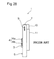
- Fig. 27 shows a plan view of a prior art machine .
- a cartridge with its memory cell having a memory of a program data is built in the machine, a game play is started.
- Fig.28 is a side view of the Fig. 27 seen from an arrow A.
- a numeral 1 is a game machine .
- a LCD display portion (2) is positioned on the center of the machine (1).
- a cruciform shifting key (3) is formed as a first operative means on the slight lower and left position of the machine and on the left side of the display portion (2) to be operated by a thumb of a left hand (B).
- This key (3) is established in bulging cruciform toward its center with a round skirt, and the key (3 )develops to move a character of the game in the direction of "Up and Down" and "Left and Right” .
- This key (3) also decides the character of the game after the selection of starting game .
- a set key (4) comprising a passive movement key (4a) and a active movement key (4b) is formed as a second operative means to be operated by a thumb of a right hand (C).
- the passive movement key (4a) provides a passive movement, such as offering jumpings or lying downs for the character in case of receiving enemy attacks in the game
- the active movement key (4b) provides a active movement such as offering attacks for the character against its enemy in the game.
- a start key (5) is positioned to be operated by the right thumb (C), and on the upper and central portion of the machine (1), a speaker (6) is positioned.
- a switch (7), a volume controller (8) and a luminance controller (9) are furnished, and all of these equipments can be controlled by either of right or left thumb.
- an insertion hole (11) is prepared to receive a cartridge (10) with which a memory cell is installed storing a game program data.
- an operative function is offered to the cruciform key (3) to move the character in every direction as required and to specify the character for the selection of the game or for the requirements in accordance with the game situations.
- another operative function is offered to the set key (4) comprising the passive movement key (4a) and the active movement key (4b), whereas the passive movement such as jumps or lying downs is provided for the former key (4a) while the active moment such as attacks is provided or the latter key (4b). The player operates these two function keys on his disposal to enjoy the game .
- the LCD display portion (2) is produced in nearly square shape so that both vertical and horizontal scrolling games can be optionally adopted.
- square shape for the display portion (3) some dead space on the display portion (2) is unavoidable .
- both right and left sides of the portion (2) become dead spaces thereof, while if the game is performed in a horizontal display, both top and bottom sides become dead spaces. On these dead spaces, some characters or sceneries which are not required for the game development are shown.
- the LCD material used for the display portion (2) is very expensive and it constitutes a main cause to raise up the price of the hand-held LCD game machine. Thus, the material offers a very high handicap to lower the cost of the machine.
- This invention relates to a hand-held LCD game machine and a ROM cartridge and combination of the machine and the cartridge, wherein a player enjoys a game performance, watching a LCD display portion with manual operation of keys and switches by both thumbs, holding the machine by both hands.
- the present invention has an object to develop the machine with a smaller LCD material to provide a display portion in oblong shape to attain the cost down of the machine.
- the invention has a further object to provide a smaller and more compact machine by adopting the smaller LCD material built in the machine.
- the display portion is provided in oblong shape after cutting off the both sides of the portion different from the prior art in square shape, and in case if the game is proceeded in a vertical scrolling manner, the portion in oblong shape is displayed lengthwise, while in case if the game is proceeded in a horizontal scrolling manner, the portion in oblong shape is displayed sideways.
- This invention also provides plural operative means to perform the game by adopting input and output signals which are issued and caught by the machine or the inserted cartridge in accordance with the selected game, whereas the game is properly displayed on the LCD display portion.
- the plural operative means and the game program data are also memoried in the ROM cartridge, whereas the game machine may have quite a variety of its performance on choice.
- a numeral 12 is a hand-held LCD game machine, and on the middle of the machine (12) a LCD display portion (13) is positioned.
- a cruciform shift key (3) is established as a first operative means on the left side and in the vicinity of the long side (13a) of the display portion (13), and this key (3) is operated by a left thumb (B) .
- a set key (4) comprising a passive movement key (4a)) and an active movement key (4b) is established as a second operative means to be operated by a right thumb.
- a similar set key (14) comprising a passive movement key (14a) and an active movement key (14b) is established as a third operative means .
- a start key (5) is positioned so that the key (5) can be operated by the right thumb (C).
- a speaker (6) is located above the display portion (13) in the middle.
- a power switch (7), a volume controller (8) and a luminance controller (9) which controls the luminance of the display portion (13) are prepared so that these switches can be operated by either right thumb (B) or left thumb (C).
- an insertion hole (11) (not shown in the drawing) is formed to receive a cartridge (10) in which a game program data is already memoried in its cell, and thus the cartridge (10) is inserted into the hole (11).
- the cartridge (10) with a memory cell of the vertical processing is inserted into the hole (11), and as shown in FIG. 2, the machine (12) is turned round to the left at 90 degree and held by both hands with the display portion (13) in lengthwise, and the shift key (3) is operated by the left thumb (B) while the set key (14) including the passive key (14a) and the active key (14b) is operated by the right thumb (C).
- the shift key (3) is to be always operated by the left thumb (B) while the set keys (4, 14) are to be always operated by the right thumb (C), and therefore a sense of incongruity is not occurred to a player during his operation when he plays the game in the horizontal or vertical manner.
- the mutual position between the shift key (3) and the set key (4) or between the shift key (3) and the set key (14) is in the vicinity of the display portion (13) and is separated each other.
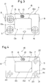
- this game machine (1 5) has a cruciform key (3), but in stead of the set keys (4 and 14), the same cruciform keys are adopted for the set keys under the numerals 16 and 17.
- the shift key (3) is positioned at the left and lower side, in the vicinity of a long side (13c) of the display portion (13) as the first operative means to be operated by the left thumb (B), while the similar cruciform key (16) as a movement key is positioned at the right and lower side, in the vicinity of the long side (13c) as the second operative means to be operated by the right thumb (C), and the similar key (17) as the third operative means is positioned at the upper and left side, in the vicinity of a short side (13b).
- a change-over switch (18) in sliding action is established, and it functions to change the shift key (3) into the movement key.
- the right half if the right half is pushed, it functions as a passive movement same as the passive key (4a) of the first embodiment, while if the left half is pushed it functions as a active movement same as the active key (4b).
- the function of the shift key (3) is to be changed into the movement key (16) .
- the shift key (3) is handled by the left thumb (B) and the movement key (16) is handled by the right thumb (C).
- the shift key (17) is handled by the left thumb (B) and the shift key (3) is now changed into the movement key to be handled by the right thumb (C).
- a shift key (20) is positioned at the left and lower side, in the vicinity of a long side (13c) of the display portion (13) as the second operative means to be handled by the left thumb (B), while the movement key (21) is positioned at the right and lower side, in the vicinity of the long side (13c) as the first operative means to be operated by the right thumb (C), and a shift key (22) is positioned at he upper and right side, in the vicinity of a short side (13d).
- buttons in high and low control the movement of the character in the game in the direction of high and low, while other two buttons in left and right also control the movement of the character in the direct of left and right.
- an upper button functions a passive movement
- a right button functions an active movement
- a left button functions a start key
- a bottom button is a reserve button.
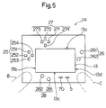
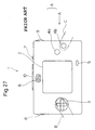
- a 4-pcs cruciform shift key (25) is prepared on the left side and a little bit upward portion of the machine (24) along a short side (13b) as the first operative means to be handled by the left thumb (B), while a 2-pcs movement key (26) in uneven steps is prepared in contrast with the shift key (25) along a short side (13d) as the second operative means to be handled by the right thumb (C).
- a 4-pcs cruciform shift key (27) having the exact function with the key (2 5) is prepared along a long side (13a) as the third operative means to be handled by the left thumb (B), while a 2-pcs movement key (28) having the same function with the key (26) is prepared along a long side (13c) as the fourth operative means .
- the cartridge (10) (not shown in the drawing) equipped with a program data of the horizontal scrolling game is built in with the machine (24), and the game is performed .
- the machine (24) is held by both hands, an upper key switch (251) is allotted a role for the character to attack its enemy toward upside, a left key switch (252) is allotted a role to move into the left direction, a bottom key switch (253) is allotted to lie down into the downward direction, and a right key switch (254) is allotted a role to move into the right direction.
- an upper key switch (261) is allotted a movement for the character to jump, and a bottom key switch (262) is allotted a movement to attack enemies with arms .
- an upper key switch (271) is allotted a role for the character to attack its enemy toward upside
- a left key switch (272) is allotted a role to move into the left direction
- a bottom key switch (273) is allotted to lie down into the downward direction
- a right key switch (274) is allotted a role to move into the right direction
- an upper key switch (281) is allotted a movement for the character to jump
- a bottom key switch (282) is allotted a movement to attack enemies with arms.
- the numeral 5 is a start key
- the numeral 70 is a select key to choose the arms to be used.
- the shift key (25) and the movement key (26) are positioned in the contrast places each other over the display portion (13) in the horizontal performance, while the shift key (27) and the movement key (28) are in the same connections therebetween in the vertical performance.
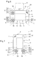
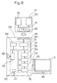
- the game machine (29) in this embodiment is equipped with a direction indicating key.
- a first direction indicating key (30) is established at the left and lower portion in the vicinity of a short side (13b) as the first operative means and the second direction key (31) is established toward the upper portion as the third operative means.
- a 2-pcs decision key (32) in uneven steps is established at the right and lower portion in the vicinity with a long side (13c) as the second operative means.
- a volume control button (8) and a start key (5) are separately formed.
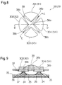
- the first direction indicating key (30) comprises a first key switch (301), a second key switch (302), a third key switch (303) and a fourth key switch (304) while the second direction indicating key (31) comprises a fifth key switch (311), a sixth key switch (312), a seventh key switch (313) and an eighth key switch (313).
- the decision key (32) comprises a ninth key switch (321) and a tenth key switch (322).
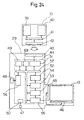
- each key switch has a key top to be pushed, a switch pattern (34) formed on the substrate (33) of the game machine (29), a dome-like restorable material (35) with flat top covering the switch pattern (34) and a conductive material (36) formed on said flat top.
- a switch pattern 34) formed on the substrate (33) of the game machine (29)
- a dome-like restorable material 35) with flat top covering the switch pattern (34)
- a conductive material (36) formed on said flat top.
- each key top contacts on the flat and upper surface of the restorable material (35) and protrudes through a housing (37) of the machine (29) .
- the restorable material (35) is transformed to contact on the switch pattern (34), which causes to close the circuit of the key switch.
- the material (35) restores into its original form so that the conductive material (36) is apart from the switch pattern (34) to cause the opening of the circuit.
- the four key tops (301, 302, 303, and 304) in the first indicating key (30) and the other four key tops (311, 312, 313 and 314) in the second indicating key (31) are separated by the partitioned wall (38) extending upward in X-letter like form from the surface of the housing (37).
- This wall (38) is swelled in the middle and inclines toward its end in all four directions, and the top end is entering into the surface of the housing (37) around the outer circumference of the corresponding key top.
- all key tops (301, 302, 303, 304, 311, 312, 313 and 314) are separated by the partitioned wall (38) including the center portion (38a) and the end portion (38b), and thus they are all independent.
- each key top can be pushed by the thumb independently so that adjoining key tops may not be pushed together.
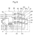
- FIG. 11 shows a circuit of the switch mechanism shown in FIG. 9 and FIG. 10, the conductive material are shown in a chain line.
- a program ROM (39) with which a game program for the horizontal or/and vertical scrolling game are memoried, a saving RAM (40), a bus (41) and a cassette connector (42) are prepared.
- the saving RAM (40) stores temporarily the datum of the program ROM (39) and other data required for game processing such as item data or clear stage data.
- the connector (42) is connected with the program ROM (39) and the saving RAM (40) via the bus (41).
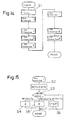
- a machine connector (43), a system LSI (44), a LCD display portion (13), a crystal oscillator (47) and an operation portion (48) are prepared.
- the connector (43) connects with the cassette connector (4 2), while the system LSI (44) reads the program data issued by the ROM (39) based on the input signal and controls the processing of the game properly and this LSI (44) also controls the image on the display portion (13).
- the display portion (13) is connected with the LSI (44) via a LCD common driver (45) and a LCD segment driver (46).
- the crystal oscillator (47) is arranged to cause a clock signal with simultaneous timing with the system LSI (44) .
- the operation portion (48) comprises a start key (5), the first and second direction indicating keys (30 and 31) and the decision key (32).
- a speaker (5), a volume controller (8), a power supply switch (7), a luminance controller (9) and other peripheral devices including a power supply are omitted.
- the system LSI (44) in the first place performs to initialize a register, RAM, a system area and also performs to indicate a logo mark.
- the LSI (44) is composed of, a CPU core (49) which reads the program data from the program ROM (39) of the cartridge (10) and outputs the relative results to each required device, an oscillating circuit (50) to issue a clock signal based on a pulse signal issued by the crystal oscillator (47), a bus interface (51) formed to input or output the data between the machine (29) and the cartridge (10), and an inner RAM (52) which temporarily stores various data like indicated and sounded data .
- the LSI (44) is connected with this inner RAM (52) to control the data areas thereof.
- the LSI (44) also includes a DMA controller (54) which transfers various data to a display controller (53) and a sound controller (not indicated in the drawing) without any control of the CPU core (4 9), a display controller (53) which is connected with the DMA controller (54) and changes co-ordinates, fonts, and screens transmitted from the inner RAM (52) into the display data, a LCD interface (55) which is connected with the display controller (53), positioned between the LCD common driver (45) and the LCD segment driver (46) and changes the display data into the data to be displayed at the display portion (13), a key interface (51) which is connected with the operation portion (48), and a inner bus (57) which connects the CPU core (49), the bus interface (51), the inner RAM (52), the DMA controller (54), the display controller (53), the LCD interface (55) and a key interface (56).
- a DMA controller which transfers various data to a display controller (53) and a sound controller (not indicated in the drawing) without any control of the CPU core (4 9
- the other end of the terminal of the ninth key switch (321) is connected with the input side of a NOT circuit (59) which is linked with a signal wire (KEYIN 3) OF a key scan input signal to be read by the CPU core (49), and similarly the other end of the terminal of the tenth key switch (322) is connected with the input side of a NOT circuit (60) linked with a signal wire (KEYIN 2) while the other end of the terminal of the start key (5) is connected with a NOT circuit (61) linked with a signal wire (KEYIN 1).
- the other end of the terminal of the second key switch (302) is connected with the input side of the NOT circuit (59), and similarly the other end of the terminal of the third key switch (303) is connected with the input side of the NOT circuit (60), and the other end of the terminal of the fourth key switch (304) is connected with the input side of the NOT circuit (61), while the other end of the terminal of the first key switch (301) is connected with the input side of a NOT circuit (63) which is linked with a signal wire (KEYIN 0).
- a NOT circuit (64) wherein a signal wire (KEYOUT 0) of the key scan output signal is connected into the input side, four pieces of the reverse diodes are connected in parallel, and onto the input side of each diode, one end of each terminal of the sixth key switch (312), the seventh key switch (313), the eighth key switch (314) and the fifth key switch (311) is connected, while the other end of each terminal in the key interface (56) is connected with a power supply to cause a voltage (H) via a pull up resistance (R).
- the other end of the terminal of the sixth key switch (312) is connected with the input side of the NOT circuit (59), and similarly the other end of the terminal of the seventh key switch (313) is connected with the input side of the NOT circuit (60), and the other end of the terminal of the eighth key switch (314) is connected with the input side of the NOT circuit (61), while the other end of the terminal of the fifth key switch (311) is connected with the input side of a NOT circuit (63).
- the CPU core (49) reads the key scan input signals in the key interface (56) and judges whether the switch circuit is open or closed. In other words, when the switch circuit is open, all input signal wires (KEYIN 3, KEYIN 2, KEYIN 1, and KEYIN 0) show "L" conditions.
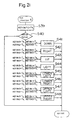
- a cartridge (10) wherein a horizontal scrolling game is momoried is now inserted into the machine (29) for the sideways display on the display portion (13), and the cassette connector (42) is connected with the game connector (43), the power is supplied by the switch (7).
- the CPU core (49) reads a game program data of the program ROM (39) of the cartridge via the bus interface (51).
- the displayed data are now memoried and stored temporarily into the inner RAM (52).
- the data temporarily stored in the RAM (52) is transmitted to a display controller (53) through a DMA controller (54).
- the displayed data are converted into dots display data in the display controller (53), and the converted data of dots display are by the control of the CPU core (49) transmitted to the display portion (13) through a LCD interface (55) via a LCD common driver (45) and a LCD segment driver (46), and finally the title of the game is shown in sideways on the display portion (13) as a Step S1.
- the subroutine 1 is performed whether a decision key (32) is put on or not.
- the "H" key scan output signal is caused in the signal wire (KEYOUT 2) as the Step S2 and the "H" key scan input signal is caused in the signal line (KEYIN 3), then an operation function "A" as a Step S4 is allotted to the ninth key (321) of the decision key (32) to provide functions of jumpings or attacks.
- an operation function "B" as a Step S5 is allotted to the tenth key switch (322) of the decision key (32) to provide functions of circumstances settings or optional powers .
- the subroutine 2 is performed whether a first direction indicating key (30) is put on or not.
- the "H" key scan output signal is caused in the signal wire (KEYOUT 1) as a Step S7 from the key interface (56), and the CPU core (49) judges as a Step S8 whether the key scan input signal from the signal wires (KEYIN 3, KEYIN 2, KEYIN 1 and KEYIN 0) is "L" or "H".
- an operation function "LEFT” as a Step S9 is allotted to the second key switch (302) of the first direction key (30) to provide the functions to move the character of the game or the cursor into the left direction.
- an operation function "DOWN” as a Step S10 is allotted to the third key switch (30 3) of the first direction key (30) to provide the functions to move downwards
- an operation function "RIGHT” as a Step S11 is allotted to the fourth key switch (304) of the first direction key (30)
- an operation function "UP” as a Step S12 is allotted to the first key switch (301) respectively.
- the subroutine 3 is performed whether a second direction indicating key (31) is put on or not.
- the "H" key scan output signal is caused in the signal wire (KEYOUT 0) as a Step S17 from the key interface (56), and the CPU core (49) judges as a Step S18 whether the key scan input signal from the signal wires (KEYIN 3, KEYIN 2, KEYIN 1 and KEYIN 0) is "L" or "H".
- the first and the second direction indicating keys (30 and 31) have functions to instruct the movement directions or movement changes, while the decision key (32) has functions to instruct some special actions or commands. It is also available to program the second direction indicating key ( 31 ) as the annulment key , or else to program as the other special action key.
- the cartridge wherein a vertical scrolling game is memoried is now inserted into this game machine (29).
- the title of the game is shown in lengthwise on the display portion (13) as a Step S27, and during the game is in progress, the subroutine 4 is performed.
- the "H" key scan output signal is caused in the signal wire (KEYOUT 2) as the Step S2 8
- the CPU core (49) judges as a Step 29 the key scan input signal issued from the signal wires (KEYIN 3, KEYIN 2 and KEYIN 2) comes into the key interface (5 6) .
- the subroutine 5 is performed .
- the "H" key scan output signal as a Step S33 is caused from the signal wire (KEYOUT 1) , and the judgement as a Step S34 is made, and then when the "H" key scan input signal is caused from the signal wire (KEYIN 3), as a Step S35 the function "A" is allotted, whose function is the same as the second key switch (302) of the first direction indicating key (30) to move "LEFT” and as the ninth key switch (321) of the decision key (32) to offer jumps and attacks.
- Step S36 When the "H" key scan input signal is caused from the signal wire (KEYIN 2), as a Step S36 the function "B" is allotted, whose function is the same as the third key switch (303) of the first direction indicating key (30) to move "DOWN” and as the tenth key switch (322) of the decision key (3 2) to offer game circumstances and options.
- Step S37 When the "H” key scan input signal is caused from the signal wire (KEYIN 1), as a Step S37 the function "D” is allotted, whose function is the same as the fourth key switch (304) of the first direction indicating key (30) to move "RIGHT", while when the "H” key scan input signal is caused from the signal wire (KEYIN 0), as a Step S38 the function "C” is allotted, whose function is the same as the first key switch (304) of the first direction indicating key (30) to move "UP".
- the subroutine 6 is performed .
- the "H" key scan output signal as a Step S39 is caused from the signal wire (KEYOUT 0) , and the judgement as a Step S40 is made, and then when the "H" key scan input signal is caused from the signal wire (KEYIN 3), as a Step S41 the function "DOWN" is allotted to the sixth key switch (312) of the second direction indicating key (31) to start active movements like attacks toward downwards .
- Step S42 the function "RIGHT” is allotted to the seventh key switch (313) of the second direction indicating key (31) to move the character and cursor into right direction.
- Step S43 the function "UP” is allotted to the eighth key switch (314) of the second direction indicating key (31) to offer active movements toward upwards, while when the "H" key scan input signal is caused from the signal wire (KEYIN 0), as a Step S44 the function "LEFT” is allotted to the fifth key switch (314) of the second direction indicating key (31) to move "UP".
- the ninth and tenth keys (321 and 322) of the decision key (32) may be programed as the annulment key, while the first and forth key switch (301 and 304) are also treated as the annulment key.
- the subroutines 1, 2 and 3 are adopted for horizontal display as shown in FIG. 15, FIG. 16 and FIG. 17, while the subroutines 4, 5 and 6 are adopted for vertical display as shown in FIG. 19, 21 and 22.
- the first key switch (301) of the first direction indicating key (30) is allotted with the "UP" function to offer active movements toward the upside, while, as shown in FIG . 7, where the machine (29) is held lengthwise, namely in the vertical display, the "UP" function allotted to the first key switch (301) is now changed to be allotted to the eighth key (314) of the second direction indicating key (31).
- the active functions allotted to the first and second direction indicating key (30 and 31) may be changed to decide the shifting direction or the attacking directions through the selection of the decision key (32).
- the constitution of the first and second direction indicating keys (30 and 31) provides a X-letter like division wall (38) on the middle separating four key switch tops and this constitution makes it possible to operate the key tops independently and also to operate plural tops together, and at the same time those tops can be used as a direction indicating key or a decision key for the first and second direction indicating keys (30 and 31).
- This constitution provides both functions to be operated independently and to be operated as a single switch , which offers a good operability for the machine (29).
- the height of the key top protruding from the surface of the housing (37) it should be adapted not to close the switch circuit when the thumb is placed over the central portion (38a) of the division wall (38), and this height is acceptable higher or lower than the central portion (38) .
- conductive rubber may be used as the conductive material.
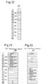
- FIG. 22 is a block chart showing a scan register
- FIG . 23 is a block chart showing an operation function memory
- the FIG . 23(a) shows an operation function memory for the horizontal display
- the FIG. 23 (b) shows an operation function memory for the vertical display
- the scan register (65) as a means of allotting functions is formed in the key interface (56).
- a flag of the bit "1" as function signal stands when each key switch circuit of each independent register (5, 301 ⁇ 304, 311 ⁇ 314, 321 and 322) is closed, and the flag of the bit “1” also stands when each key switch circuit of each adjoining register (301/302, 302/303, 303/304, 304/301, 311/3 12, 312/313, 313/314 and 314/311) is closed.
- Operation function memories comprise a function memory (66) for the horizontal display and a function memory (67) for the vertical display, and they are formed in the saving RAM (40) in correspondence with the scan register (65).
- the "H” key scan output signal is caused in the signal wire (KEYOUT 1) from the key interface (56) through the control of the CPU core (49) in order to judge whether the first direction indicating key (30) is pushed on or not.
- the flag of the bit “1” stands at the register (302) of the scan register (65).
- the key interface (56) is always scanning the scan register (65), and once the "1" flag stands, through the control of the CPU core (49), the second key switch (302) of the first direction indicating key (30) is allotted to the operation function "LEFT" to shift the character or the cursor into the left direction, and thus the game is performed.
- the title of the game is displayed accordingly in sideways or lengthwise.
- the operation function memory (66) for the horizontal display is adopted, while, when the game is proceeded in the vertical manners, the function memory (67) is adopted.
- the operation function memories (66 and 67) can be established in the inner RAM (52), and when the game program is performed, all function data are read from the program ROM (39) and can be stored in the memories (66 and 67) in correspondence with the scan register (65).
- the function signals for operation are obtained by a set of the operative means constituted from the first direction indicating key (30) and the decision key (32), while, in the vertical scrolling game, the same function signals are obtained by the corresponding operative means constituted from the second direction indicating key (31) and the first direction indicating key (30).
- function data for operation are memoried with the saving RAM of the cartridge or with the inner RAM of the machine in the proper guidance of the horizontal or vertical scrolling game .
- FIG. 6 ⁇ FIG. 11, FIG. 13 ⁇ FIG. 21 and FIG. 24 ⁇ FIG. 26.
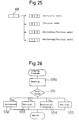
- FIG . 24 is a block chart explaining the general circuit between the cartridge and the machine
- FIG. 25 is a block chart explaining a decision memory for the vertical or horizontal pattern
- FIG. 26 is a flow chart explaining a decision program for the vertical or horizontal pattern.
- the numeral 68 is a decision memory for the vertical or horizontal display as a data memory means and it is established in the program ROM (39) of the cartridge (10).
- the numeral 69 is a inner ROM which is connected with the inner bus of the system LSI (44) .
- a decision data comprising 2-bit capacity to judge the vertical or horizontal game is equipped.
- Step S50 the CPU core reads the horizontal or vertical decision datum in the memory (68), whose datum is memoried the specified address of the program ROM (39) .
- the datum shows "00" as a Step S51
- a logo mark for horizontal scrolling is shown on the display portion (13) as a Step S52
- the program as explained in FIG. 14 ⁇ FIG. 17 is performed.
- the program shown in FIG. 18 ⁇ FIG. 21 is performed.
- the decision memory can be provided separately from the program ROM (39) . At the same time, this memory can be also provided by a circuit in stead of using the inner ROM (69).
- the decision memory (68) As the decision memory (68) is established in the cartridge (10), it is easily recognized whether the cartridge (10) is usable with the game machine (29) immediately, and the player can confirm the mode of the game clearly before his starting.
- a scan register (65) is established in a key interface (56), and similar to the sixth embodiment an operative function memory is established in a saving RAM (40), while similar to the seventh embodiment a decision memory (68) is established in a cartridge (10).
- each operative function is stored into two operative function memories (66 and 67) in correspondence with each register of the scan register (65). Then, similar to the sixth embodiment, each operative function is allotted properly and the game is performed.
- the operative function memories (66 and 67) can be established in the inner RAM (57).
- FIG. 1 The present embodiment is now explained with reference to FIG. 1, FIG. 2 and FIG. 6 ⁇ FIG. 21.
- This embodiment adopts the game machine (12) of the first embodiment in the system of the fifth embodiment. Except the game machine (29), the difference resides where the key top of the shift key (3) is a round cruciform shape and where a set key (4 and 14) as the movement key is positioned apart from the shift key (3).
- the mechanism of the key switch is exactly same as that adopted in the fifth embodiment.
- the upper side switch of the shift key (3) functions as the first key switch (301) of the direction indicating key (30) in the machine (29), and the left side key switch of the shift key (3) functions as the second key switch (302).
- the lower side key switch of the shift key (3) functions as the third key switch (303), while the right side key switch of the shift key ( 3 ) functions as the fourth key (304).
- the passive moment key (4a) of the set key (4) functions as the tenth key switch (32 2) of the decision key (32), while the active moment key (4b) of the set key (4) functions as the ninth key (321) of the decision key (32) .
- the upper side switch of the shift key (3) which is exactly same as the right side key switch in the horizontal display functions as the eighth key switch (314) of the direction indicating key (31) in the machine (29), and the left side key switch of the shift key (3) functions as the fifth key switch (311).
- the lower side key switch of the shift key (3) functions as the sixth key switch (312), while the right side key switch of the shift key (3) functions as the seventh key (313).
- the passive moment key (14a) of the set key (14) functions as the third key switch (303) of the direction indicating key (30), while the active moment key (14b) of the set key (14) functions as the second key (302) of the direction key (30).
- FIG. 3 FIG. 6 ⁇ FIG . 13, FIG. 22 and FIG. 23.
- This embodiment adopts the game machine (15) of the second embodiment in the system of the sixth embodiment.
- the operative function memories (66 and 67) are established in the inner RAM (57) of the machine (15). Except the machine (15), the difference resides where the key top of the shift keys (3 and 17) and the movement key (16) is a round cruciform shape and where a change-over switch (18) is formed in order to change the function of the shift key (3) into that of the movement key (16).
- the inner mechanism of the key switch is exactly same as shown in FIG. 9 ⁇ FIG. 11 except the key top.
- the upper side key switch and the left side key switch of the movement key (16) may be used as the reserve keys.
- This embodiment adopts the game machine (19) of the third embodiment in the system of the fifth embodiment.
- the upper side switch of the shift key (20) functions as the first key switch (301) of the direction indicating key (30) in the machine (29), and the left side key switch of the shift key (20) functions as the second key switch (302).
- the lower side key switch of the shift key (20) functions as the third key switch (303), while the right side key switch of the shift key (20) functions as the fourth key (304).
- the passive moment key (4a ) of the movement key (21) functions as the tenth key switch (322) of the decision key (32), while the active moment key (4b) of the movement key (21) functions as the ninth key (321) of the decision key (32).
- the upper side switch of the shift key (22) functions as the eighth key switch (314) of the direction indicating key (31) in the machine (29), and the left side key switch of the shift key (22) functions as the fifth key switch (311).
- the lower side key switch of the shift key (22) functions as the sixth key switch (312), while the right side key switch of the shift key (22) functions as the seventh key (313).
- the passive moment key (4a) of the movement key (21) functions as the tenth key switch (322) of the decision key (32), while the active moment key (4b) of the movement key (21) functions as the ninth key switch (321) of the decision key (32) .
- This embodiment adopts the game machine (24) of the fourth embodiment in the system of the fifth embodiment.
- the upper side switch (251) of the shift key (25) functions as the first key switch (301) of the direction indicating key (30) in the machine (29), and the left side key switch (252) of the shift key (25) functions as the second key switch (302).
- the lower side key switch (253) of the shift key (25) functions as the third key switch (303), while the right side key switch (254) of the shift key (25) functions as the fourth key (304).
- the upper side key switch (261) of the movement key (26) functions as the tenth key switch (322) of the decision key (32), while the lower side key switch ( 262 ) of the movement key ( 26 ) functions as the ninth key (32 1) of the decision key (32).
- the upper side switch (271) of the shift key (27) functions as the eighth key switch (314) of the direction indicating key (31) in the machine (29), and the left side key switch (272) of the shift key (27) functions as the fifth key switch (3 11).
- the lower side key switch (273) of the shift key (27) functions as the sixth key switch (312), while the right side key switch (274) of the shift key (27) functions as the seventh key (313).
- the upper side key switch (281) of the movement key (28) functions as the third key switch (303) of the direction indicating key (30), while the lower key switch (282) of the movement key (28) functions as the second key switch (302) of the direction key (30).
- the language of the operative function means the actions of the character in the game for shifting, stoppage, jumping and so on, or it means the function to display and control the character in the game. For example, when the operative function is given to the direction key, the character is to move in the direction of the key.
- the horizontal scrolling game is performed in the horizontal LCD display portion, while the vertical scrolling game is performed in the vertical LCD display portion, but it should be granted as a matter of course that the horizontal game can be also proceeded in the vertical display while the vertical game can be also proceeded in the horizontal display.
- any kind of the program data such as the horizontal, vertical, horizontal/vertical mixed displays can be available in this invented machine.
- plural operative means are provided for the hand-held LCD game machine so that the game can be operated both in lengthwise or sideways condition with the proper LCD display portion in compliance with the horizontal , vertical or horizontal/vertical mixed scrolling game .
- the invention has realized the oblong shape of the LCD display in smaller size than the before, where the almost square LCD display is unavoidable in prior art. By this realization, this invention can provide both the low cost and the more compact size by minimizing the LCD display .
- the plural operative means are positioned in proper places, so that the good and desirable operability can be obtained thereof in actual play operation with good combinations of the machine and the cartridge as provided.
Abstract
Description
Claims (16)
- In a hand-held LCD game machine into which a cartridge equipped with a memory cell of a game program datum inserted and with which a game is developed on a LCD display portion, wherein a first operative means is positioned at a place to be handled by one thumb and a second operative means is also positioned at another place to be handled by the other thumb, the improvement comprises :the LCD display portion is formed at an oblong shape;the first operative means and the second operative means are established in the vicinity of and apart from one side of the display portion; anda third operative means with the similar functions of the first or the second means is established in the vicinity of the other side of the display portion and apart from the first operative means .
- The game machine according to Claim 1, wherein the third operative means has similar functions of the second operative means.
- The game machine according to Claim 1, wherein the third operative means has similar functions of the first operative means while the first operative means is adapted to have similar functions of the second operative means in stead of its first functions.
- In a hand-held LCD game machine into which a cartridge equipped with a memory cell of a game program datum and a game is developed on a LCD display portion, wherein a first operative means is positioned at a place to be handled by one thumb and a second operative means is also positioned at another place to be handled by the other thumb, the improvement comprises :the LCD display portion is formed at an oblong shape;the first operative means and the second operative means are established in the vicinity of two opposite sides of the display portion in the condition that the display portion is sandwiched between these two means ; andthe third operative means with the similar functions of the first means and a fourth operative means with the similar functions of the second means are established in the vicinity of the other and two opposite sides of the display portion in the condition that the display portion is sandwiched between these two mans.
- The game machine according to Claim 1, wherein operative functions are allotted to operative means in correspondence with a game program datum when a cartridge is inserted into the game machine and thus the operative means have the functions.
- The game machine according to Claim 1, wherein when a cartridge in which a horizontal scrolling game program data is memoried is inserted into the game machine operative functions are allotted to a set of operative means positioned apart from a longer side of the LCD display portion while when the cartridge in which a vertical scrolling game data is memoried is inserted in the game machine the operative functions are allotted to another set of operative means positioned apart from a shorter side of the LCD display portion.
- The game machine according to Claim 1, wherein when a cartridge in which a horizontal/vertical mixed scrolling game program data is memoried is inserted into the game machine operative functions are adapted to be allotted to a set of operative means positioned apart from a longer side of the LCD display portion in case of the horizontal game while in case of the vertical game operative functions are allotted to another set of operative means positioned apart from a shorter side of the LCD display portion.
- The game machine according to Claim 1, wherein the operative functions allotted to the operative means includes the instructions to move the character or the background scene shown on the display portion.
- The game machine according to Claim 8, wherein the operative means to move the character or the background scene comprises a cruciform switch composed of four pieces key switches and each top of the key switch is separated by a X-letter like partitioned wall swelled in the middle and inclining toward its end in four directions .
- The game machine according to Claim 1, wherein when the horizontal scrolling game is running the signal of the operative function is allotted to the program datum to proceed a set of operative means positioned apart from the longer side of the LCD display portion while when the vertical scrolling game is running the signal is allotted to the program datum to proceed another set of the operative means positioned apart from the shorter side of the LCD display portion.
- The game machine according to Claim 1, wherein a decision means to judge whether the horizontal scrolling game is memoried or the vertical scrolling game is memoried is prepared in the cartridge to be inserted into the game machine.
- A cartridge to be inserted into the game machine and to be equipped with the game program datum memory, wherein when the horizontal scrolling game datum is memoried the means to proceed a set of operative means positioned apart from the longer side of the LCD display portion is prepared while when the vertical scrolling game datum is memoried the means to proceed another set of operative means positioned apart from the shorter side of the LCD display portion is also prepared.
- The cartridge according to Claim 12, wherein, when a game program datum is memoried so that the character or the background scene is developed in the horizontal display as well as the horizontal/vertical mixed movements of the character or the background scene is developed in the vertical display, the means to proceed a set of operative means positioned apart from the longer side of the LCD display portion is provided in case of the horizontal display while the means to proceed another set of operative means positioned apart from the shorter side of the LCD display portion is offered in case of the vertical display.
- The cartridge according to Claim 12, wherein a data memory means is prepared in order to judge whether a horizon scrolling game datum is memoried or a vertical scrolling game datum is memoried.
- The cartridge according to Claim 14, wherein the data memory means is established in the memory cell.
- Combination of a hand-held LCD game machine and a cartridge, wherein the game machine and the cartridge in which the program datum for the game procedures is memoried in the cell are combined.
Applications Claiming Priority (6)
| Application Number | Priority Date | Filing Date | Title |
|---|---|---|---|
| JP358198/96 | 1996-12-27 | ||
| JP35819896 | 1996-12-27 | ||
| JP35819896 | 1996-12-27 | ||
| JP32713497A JP3198084B2 (en) | 1996-12-27 | 1997-11-11 | Handheld liquid crystal game machine, cartridge incorporating storage element storing game program data, and game system combining handheld liquid crystal game machine and cartridge |
| JP32713497 | 1997-11-11 | ||
| JP327134/97 | 1997-11-11 |
Publications (3)
| Publication Number | Publication Date |
|---|---|
| EP0850672A2 true EP0850672A2 (en) | 1998-07-01 |
| EP0850672A3 EP0850672A3 (en) | 1999-12-01 |
| EP0850672B1 EP0850672B1 (en) | 2004-10-13 |
Family
ID=26572395
Family Applications (1)
| Application Number | Title | Priority Date | Filing Date |
|---|---|---|---|
| EP97122952A Expired - Lifetime EP0850672B1 (en) | 1996-12-27 | 1997-12-29 | LCD game machine and ROM cartridge |
Country Status (6)
| Country | Link |
|---|---|
| US (2) | US6764400B1 (en) |
| EP (1) | EP0850672B1 (en) |
| JP (1) | JP3198084B2 (en) |
| AT (1) | ATE279243T1 (en) |
| DE (1) | DE69731172D1 (en) |
| HK (1) | HK1014887A1 (en) |
Cited By (2)
| Publication number | Priority date | Publication date | Assignee | Title |
|---|---|---|---|---|
| US10173132B2 (en) | 2004-03-31 | 2019-01-08 | Nintendo Co., Ltd. | Game console |
| US11278793B2 (en) | 2004-03-31 | 2022-03-22 | Nintendo Co., Ltd. | Game console |
Families Citing this family (24)
| Publication number | Priority date | Publication date | Assignee | Title |
|---|---|---|---|---|
| JP3198084B2 (en) * | 1996-12-27 | 2001-08-13 | 株式会社バンダイ | Handheld liquid crystal game machine, cartridge incorporating storage element storing game program data, and game system combining handheld liquid crystal game machine and cartridge |
| JP3847058B2 (en) * | 1999-10-04 | 2006-11-15 | 任天堂株式会社 | GAME SYSTEM AND GAME INFORMATION STORAGE MEDIUM USED FOR THE SAME |
| KR100800040B1 (en) * | 2000-03-08 | 2008-01-31 | 기븐 이미징 리미티드 | A capsule for in vivo imaging |
| US20020006815A1 (en) * | 2000-05-31 | 2002-01-17 | Andrea Finke-Anlauff | Foldable keyboard for mobile communications device |
| JP3671883B2 (en) * | 2001-08-15 | 2005-07-13 | ソニー株式会社 | Image recording / playback device |
| US20040185934A1 (en) * | 2003-03-21 | 2004-09-23 | Vision Electronics Co., Ltd. | Game cotroller with an alarm clock |
| US7771280B2 (en) | 2004-03-31 | 2010-08-10 | Nintendo Co., Ltd. | Game console connector and emulator for the game console |
| US7333219B2 (en) * | 2005-03-29 | 2008-02-19 | Mitutoyo Corporation | Handheld metrology imaging system and method |
| US9030497B2 (en) * | 2005-06-30 | 2015-05-12 | Nec Display Solutions, Ltd. | Display device and arrangement method of OSD switches |
| JP5330640B2 (en) | 2006-05-09 | 2013-10-30 | 任天堂株式会社 | GAME PROGRAM, GAME DEVICE, GAME SYSTEM, AND GAME PROCESSING METHOD |
| US20080182669A1 (en) * | 2007-01-26 | 2008-07-31 | Alan Amron | Game and video cartridge for portable electronic device |
| US20080180302A1 (en) * | 2007-01-26 | 2008-07-31 | Digital Video Chip, Llc | Universal remote control |
| US8010711B2 (en) * | 2007-01-26 | 2011-08-30 | Digital Video Chip, Llc | Universal multimedia |
| US20080182670A1 (en) * | 2007-01-26 | 2008-07-31 | Alan Amron | Game and video cartridge for a host device |
| JP2009211159A (en) * | 2008-02-29 | 2009-09-17 | Brother Ind Ltd | Terminal device |
| US8454436B2 (en) * | 2008-06-26 | 2013-06-04 | Wms Gaming Inc. | Gaming machine with movable display screen |
| CN101732874B (en) * | 2008-11-14 | 2012-02-08 | 上海九鹰电子科技有限公司 | Model aeroplane remote controller |
| JP4636462B2 (en) * | 2009-03-30 | 2011-02-23 | 富士通東芝モバイルコミュニケーションズ株式会社 | Portable machine |
| JP5135404B2 (en) * | 2010-09-30 | 2013-02-06 | 株式会社東芝 | Information processing device |
| US20130204712A1 (en) * | 2012-01-25 | 2013-08-08 | Tourwrist, Inc. | Systems and Methods for Monetizing Advertisement Locations of Virtual Tour Applications |
| JP5395945B2 (en) * | 2012-11-08 | 2014-01-22 | 株式会社東芝 | Information processing device |
| JP6285900B2 (en) * | 2015-09-02 | 2018-02-28 | 株式会社ソニー・インタラクティブエンタテインメント | Operating device |
| KR102481632B1 (en) * | 2016-04-26 | 2022-12-28 | 삼성전자주식회사 | Electronic device and method for inputting adaptive touch using display in the electronic device |
| US20220261094A1 (en) * | 2021-02-17 | 2022-08-18 | Elo Touch Solutions, Inc. | Device tilt angle and dynamic button function |
Citations (3)
| Publication number | Priority date | Publication date | Assignee | Title |
|---|---|---|---|---|
| GB2226768A (en) * | 1989-01-10 | 1990-07-11 | Nintendo Co Ltd | Hand-held electronic game |
| US4969647A (en) * | 1989-06-02 | 1990-11-13 | Atari Corporation | Invertible hand-held electronic game apparatus |
| US5276831A (en) * | 1986-11-19 | 1994-01-04 | Nintendo Co. Limited | Memory cartridge having a multi-memory controller with memory bank switching capabilities and data processing apparatus |
Family Cites Families (27)
| Publication number | Priority date | Publication date | Assignee | Title |
|---|---|---|---|---|
| US134391A (en) * | 1872-12-31 | Improvement in bolts | ||
| US4359222A (en) * | 1978-10-30 | 1982-11-16 | Smith Engineering | Hand-held electronic game playing device with replaceable cartridges |
| US4334679A (en) * | 1980-01-24 | 1982-06-15 | Doyle Holly Thomis | Hand-held pinball game |
| GB2070810B (en) * | 1980-02-28 | 1984-08-15 | Nintendo Co Ltd | Timepiece apparatus having game function |
| JPS579480A (en) * | 1980-06-19 | 1982-01-18 | Nintendo Co Ltd | Figure displaying game device |
| JPS57108789A (en) * | 1980-12-26 | 1982-07-06 | Nintendo Co Ltd | Timepiece device with game function |
| US4401304A (en) * | 1981-01-05 | 1983-08-30 | Tomy Kogyo Co., Inc. | Electronic tennis game with interactive controls |
| US4386776A (en) * | 1981-02-17 | 1983-06-07 | Coleco Industries, Inc. | Electronic sports-action game with improved game-object simulation |
| US4504062A (en) * | 1981-06-04 | 1985-03-12 | Smith Engineering | Digital watch having matrix display for arcade-like game playing |
| EP0103571A1 (en) * | 1982-01-25 | 1984-03-28 | Entex Industries, Inc. | Hand held electronic game with interchangeable cartridges |
| CA1234981A (en) * | 1983-08-01 | 1988-04-12 | Gunpei Yokoi | Liquid crystal display unit |
| US5184830A (en) | 1989-01-10 | 1993-02-09 | Nintendo Company Limited | Compact hand-held video game system |
| US5026058A (en) * | 1989-03-29 | 1991-06-25 | Eric Bromley | Electronic baseball game apparatus |
| US4992631A (en) * | 1989-06-02 | 1991-02-12 | Atari Corporation | Multi-directional switch assembly |
| US5150899A (en) * | 1990-01-26 | 1992-09-29 | Konami Co., Ltd. | Hand held video game with simulated rescue |
| US5137277A (en) * | 1990-01-26 | 1992-08-11 | Konami Co., Ltd. | Hand held video game with simulated air battle |
| JP2627208B2 (en) * | 1990-06-14 | 1997-07-02 | 株式会社セガ・エンタープライゼス | Game device and television tuner cartridge for game device |
| DE4034166A1 (en) * | 1990-10-26 | 1992-04-30 | Cherry Mikroschalter Gmbh | Position control of screen cursor - has input element that can be moved, in X-Y plane with spring return to neutral position |
| US5476261A (en) * | 1992-05-07 | 1995-12-19 | Hultstrand; Victor S. | Adaptor for a machine having a controller and buttons for operation thereof |
| US5435552A (en) * | 1993-09-27 | 1995-07-25 | Welback Enterprises Ltd. | Electronic game |
| JPH07281806A (en) | 1994-04-12 | 1995-10-27 | Matsushita Electric Ind Co Ltd | Input/output device |
| US5452960A (en) * | 1994-10-27 | 1995-09-26 | Kuhlenschmidt; Richard E. | Children's computer keyboard |
| US5685776A (en) * | 1994-11-23 | 1997-11-11 | Tiger Electronics, Inc. | Hand-held electronic game devices |
| US5795227A (en) * | 1996-06-28 | 1998-08-18 | Raviv; Roni | Electronic game system |
| JP3198084B2 (en) * | 1996-12-27 | 2001-08-13 | 株式会社バンダイ | Handheld liquid crystal game machine, cartridge incorporating storage element storing game program data, and game system combining handheld liquid crystal game machine and cartridge |
| USD414217S (en) * | 1997-12-26 | 1999-09-21 | Kabushiki Kaisha Bandai | Game machine |
| JP3330326B2 (en) * | 1998-08-04 | 2002-09-30 | 株式会社バンダイ | LCD game device |
-
1997
- 1997-11-11 JP JP32713497A patent/JP3198084B2/en not_active Expired - Fee Related
- 1997-12-23 US US08/997,477 patent/US6764400B1/en not_active Expired - Fee Related
- 1997-12-29 DE DE69731172T patent/DE69731172D1/en not_active Expired - Lifetime
- 1997-12-29 AT AT97122952T patent/ATE279243T1/en not_active IP Right Cessation
- 1997-12-29 EP EP97122952A patent/EP0850672B1/en not_active Expired - Lifetime
-
1998
- 1998-12-29 HK HK98119184A patent/HK1014887A1/en not_active IP Right Cessation
-
2004
- 2004-06-25 US US10/877,213 patent/US20040235569A1/en not_active Abandoned
Patent Citations (3)
| Publication number | Priority date | Publication date | Assignee | Title |
|---|---|---|---|---|
| US5276831A (en) * | 1986-11-19 | 1994-01-04 | Nintendo Co. Limited | Memory cartridge having a multi-memory controller with memory bank switching capabilities and data processing apparatus |
| GB2226768A (en) * | 1989-01-10 | 1990-07-11 | Nintendo Co Ltd | Hand-held electronic game |
| US4969647A (en) * | 1989-06-02 | 1990-11-13 | Atari Corporation | Invertible hand-held electronic game apparatus |
Cited By (3)
| Publication number | Priority date | Publication date | Assignee | Title |
|---|---|---|---|---|
| US10173132B2 (en) | 2004-03-31 | 2019-01-08 | Nintendo Co., Ltd. | Game console |
| US10722783B2 (en) | 2004-03-31 | 2020-07-28 | Nintendo Co., Ltd. | Game console |
| US11278793B2 (en) | 2004-03-31 | 2022-03-22 | Nintendo Co., Ltd. | Game console |
Also Published As
| Publication number | Publication date |
|---|---|
| DE69731172D1 (en) | 2004-11-18 |
| ATE279243T1 (en) | 2004-10-15 |
| HK1014887A1 (en) | 1999-10-08 |
| JP3198084B2 (en) | 2001-08-13 |
| JPH10235014A (en) | 1998-09-08 |
| US6764400B1 (en) | 2004-07-20 |
| US20040235569A1 (en) | 2004-11-25 |
| EP0850672B1 (en) | 2004-10-13 |
| EP0850672A3 (en) | 1999-12-01 |
Similar Documents
| Publication | Publication Date | Title |
|---|---|---|
| EP0850672B1 (en) | LCD game machine and ROM cartridge | |
| EP0594995B1 (en) | Game apparatus | |
| EP0665526B1 (en) | Display signal conversion apparatus for video game | |
| US6315669B1 (en) | Portable color display game machine and storage medium for the same | |
| EP1291047B1 (en) | Game system, puzzle game program, and storage medium having program stored therein | |
| US5649861A (en) | Game device for displaying game input operations on the display | |
| EP0431724B1 (en) | TV game machine | |
| US8075401B2 (en) | Hand-held game apparatus and game program | |
| US6540611B1 (en) | Portable game machine and game-advancing method | |
| US8961303B2 (en) | Game apparatus and game program | |
| EP1151773A2 (en) | Game system provided with message exchange function, game apparatus used in the game system, message exchange system, and computer readable storage medium | |
| EP0960637B1 (en) | Hand-held color display game machine and memory medium therefor | |
| EP1170043B1 (en) | Video game system | |
| JP2001212373A (en) | Hand-held liquid crystal game machine | |
| JP3304877B2 (en) | Game equipment | |
| JP3994112B2 (en) | cartridge | |
| EP1002560B1 (en) | Video game apparatus and information storage medium for video game | |
| KR19990044750A (en) | Cartridges mounted on hand held liquid crystal game consoles and hand held liquid crystal game consoles and combinations with hand held liquid crystal game consoles and cartridges | |
| JPH0213021Y2 (en) | ||
| JP4159072B2 (en) | Game input device and input attachment | |
| KR200187139Y1 (en) | Step machine | |
| JP2001282422A (en) | Radio telephony equipment | |
| JP2006006572A (en) | Game control program | |
| JP2006043416A (en) | Game system, program and computer readable information record medium | |
| KR19980061207U (en) | Pager |
Legal Events
| Date | Code | Title | Description |
|---|---|---|---|
| PUAI | Public reference made under article 153(3) epc to a published international application that has entered the european phase |
Free format text: ORIGINAL CODE: 0009012 |
|
| AK | Designated contracting states |
Kind code of ref document: A2 Designated state(s): AT BE CH DE DK ES FI FR GB GR IE IT LI LU MC NL PT SE |
|
| AX | Request for extension of the european patent |
Free format text: AL;LT;LV;MK;RO;SI |
|
| RAP1 | Party data changed (applicant data changed or rights of an application transferred) |
Owner name: KABUSHIKI KAISHA BANDAI |
|
| PUAL | Search report despatched |
Free format text: ORIGINAL CODE: 0009013 |
|
| AK | Designated contracting states |
Kind code of ref document: A3 Designated state(s): AT BE CH DE DK ES FI FR GB GR IE IT LI LU MC NL PT SE |
|
| AX | Request for extension of the european patent |
Free format text: AL;LT;LV;MK;RO;SI |
|
| 17P | Request for examination filed |
Effective date: 20000602 |
|
| AKX | Designation fees paid |
Free format text: AT BE CH DE DK ES FI FR GB GR IE IT LI LU MC NL PT SE |
|
| AXX | Extension fees paid |
Free format text: AL PAYMENT 20000602;LT PAYMENT 20000602;LV PAYMENT 20000602;MK PAYMENT 20000602;RO PAYMENT 20000602;SI PAYMENT 20000602 |
|
| 17Q | First examination report despatched |
Effective date: 20021030 |
|
| GRAP | Despatch of communication of intention to grant a patent |
Free format text: ORIGINAL CODE: EPIDOSNIGR1 |
|
| RIC1 | Information provided on ipc code assigned before grant |
Ipc: 7A 63F 13/00 A |
|
| GRAS | Grant fee paid |
Free format text: ORIGINAL CODE: EPIDOSNIGR3 |
|
| GRAA | (expected) grant |
Free format text: ORIGINAL CODE: 0009210 |
|
| AK | Designated contracting states |
Kind code of ref document: B1 Designated state(s): AT BE CH DE DK ES FI FR GB GR IE IT LI LU MC NL PT SE |
|
| AX | Request for extension of the european patent |
Extension state: AL LT LV MK RO SI |
|
| PG25 | Lapsed in a contracting state [announced via postgrant information from national office to epo] |
Ref country code: SE Free format text: LAPSE BECAUSE OF FAILURE TO SUBMIT A TRANSLATION OF THE DESCRIPTION OR TO PAY THE FEE WITHIN THE PRESCRIBED TIME-LIMIT Effective date: 20041013 Ref country code: NL Free format text: LAPSE BECAUSE OF FAILURE TO SUBMIT A TRANSLATION OF THE DESCRIPTION OR TO PAY THE FEE WITHIN THE PRESCRIBED TIME-LIMIT Effective date: 20041013 Ref country code: LI Free format text: LAPSE BECAUSE OF FAILURE TO SUBMIT A TRANSLATION OF THE DESCRIPTION OR TO PAY THE FEE WITHIN THE PRESCRIBED TIME-LIMIT Effective date: 20041013 Ref country code: IT Free format text: LAPSE BECAUSE OF FAILURE TO SUBMIT A TRANSLATION OF THE DESCRIPTION OR TO PAY THE FEE WITHIN THE PRESCRIBED TIME-LIMIT;WARNING: LAPSES OF ITALIAN PATENTS WITH EFFECTIVE DATE BEFORE 2007 MAY HAVE OCCURRED AT ANY TIME BEFORE 2007. THE CORRECT EFFECTIVE DATE MAY BE DIFFERENT FROM THE ONE RECORDED. Effective date: 20041013 Ref country code: FR Free format text: LAPSE BECAUSE OF FAILURE TO SUBMIT A TRANSLATION OF THE DESCRIPTION OR TO PAY THE FEE WITHIN THE PRESCRIBED TIME-LIMIT Effective date: 20041013 Ref country code: FI Free format text: LAPSE BECAUSE OF FAILURE TO SUBMIT A TRANSLATION OF THE DESCRIPTION OR TO PAY THE FEE WITHIN THE PRESCRIBED TIME-LIMIT Effective date: 20041013 Ref country code: CH Free format text: LAPSE BECAUSE OF FAILURE TO SUBMIT A TRANSLATION OF THE DESCRIPTION OR TO PAY THE FEE WITHIN THE PRESCRIBED TIME-LIMIT Effective date: 20041013 Ref country code: BE Free format text: LAPSE BECAUSE OF FAILURE TO SUBMIT A TRANSLATION OF THE DESCRIPTION OR TO PAY THE FEE WITHIN THE PRESCRIBED TIME-LIMIT Effective date: 20041013 Ref country code: AT Free format text: LAPSE BECAUSE OF FAILURE TO SUBMIT A TRANSLATION OF THE DESCRIPTION OR TO PAY THE FEE WITHIN THE PRESCRIBED TIME-LIMIT Effective date: 20041013 |
|
| REG | Reference to a national code |
Ref country code: GB Ref legal event code: FG4D |
|
| REG | Reference to a national code |
Ref country code: CH Ref legal event code: EP |
|
| REG | Reference to a national code |
Ref country code: IE Ref legal event code: FG4D |
|
| REF | Corresponds to: |
Ref document number: 69731172 Country of ref document: DE Date of ref document: 20041118 Kind code of ref document: P |
|
| PG25 | Lapsed in a contracting state [announced via postgrant information from national office to epo] |
Ref country code: LU Free format text: LAPSE BECAUSE OF NON-PAYMENT OF DUE FEES Effective date: 20041229 |
|
| PG25 | Lapsed in a contracting state [announced via postgrant information from national office to epo] |
Ref country code: IE Free format text: LAPSE BECAUSE OF NON-PAYMENT OF DUE FEES Effective date: 20041230 |
|
| PG25 | Lapsed in a contracting state [announced via postgrant information from national office to epo] |
Ref country code: MC Free format text: LAPSE BECAUSE OF NON-PAYMENT OF DUE FEES Effective date: 20041231 |
|
| PG25 | Lapsed in a contracting state [announced via postgrant information from national office to epo] |
Ref country code: GR Free format text: LAPSE BECAUSE OF FAILURE TO SUBMIT A TRANSLATION OF THE DESCRIPTION OR TO PAY THE FEE WITHIN THE PRESCRIBED TIME-LIMIT Effective date: 20050113 Ref country code: DK Free format text: LAPSE BECAUSE OF FAILURE TO SUBMIT A TRANSLATION OF THE DESCRIPTION OR TO PAY THE FEE WITHIN THE PRESCRIBED TIME-LIMIT Effective date: 20050113 |
|
| PG25 | Lapsed in a contracting state [announced via postgrant information from national office to epo] |
Ref country code: DE Free format text: LAPSE BECAUSE OF FAILURE TO SUBMIT A TRANSLATION OF THE DESCRIPTION OR TO PAY THE FEE WITHIN THE PRESCRIBED TIME-LIMIT Effective date: 20050114 |
|
| PG25 | Lapsed in a contracting state [announced via postgrant information from national office to epo] |
Ref country code: ES Free format text: LAPSE BECAUSE OF FAILURE TO SUBMIT A TRANSLATION OF THE DESCRIPTION OR TO PAY THE FEE WITHIN THE PRESCRIBED TIME-LIMIT Effective date: 20050124 |
|
| REG | Reference to a national code |
Ref country code: HK Ref legal event code: GR Ref document number: 1014887 Country of ref document: HK |
|
| LTIE | Lt: invalidation of european patent or patent extension |
Effective date: 20041013 |
|
| NLV1 | Nl: lapsed or annulled due to failure to fulfill the requirements of art. 29p and 29m of the patents act | ||
| REG | Reference to a national code |
Ref country code: CH Ref legal event code: PL |
|
| PLBE | No opposition filed within time limit |
Free format text: ORIGINAL CODE: 0009261 |
|
| STAA | Information on the status of an ep patent application or granted ep patent |
Free format text: STATUS: NO OPPOSITION FILED WITHIN TIME LIMIT |
|
| REG | Reference to a national code |
Ref country code: IE Ref legal event code: MM4A |
|
| 26N | No opposition filed |
Effective date: 20050714 |
|
| EN | Fr: translation not filed | ||
| PG25 | Lapsed in a contracting state [announced via postgrant information from national office to epo] |
Ref country code: PT Free format text: LAPSE BECAUSE OF NON-PAYMENT OF DUE FEES Effective date: 20050313 |
|
| PGFP | Annual fee paid to national office [announced via postgrant information from national office to epo] |
Ref country code: GB Payment date: 20141224 Year of fee payment: 18 |
|
| GBPC | Gb: european patent ceased through non-payment of renewal fee |
Effective date: 20151229 |
|
| PG25 | Lapsed in a contracting state [announced via postgrant information from national office to epo] |
Ref country code: GB Free format text: LAPSE BECAUSE OF NON-PAYMENT OF DUE FEES Effective date: 20151229 |