EP0851634A2 - Method and apparatus for dynamically reconfiguring virtual lans of a network device - Google Patents

Method and apparatus for dynamically reconfiguring virtual lans of a network device Download PDF

Info

Publication number
EP0851634A2
EP0851634A2 EP97309623A EP97309623A EP0851634A2 EP 0851634 A2 EP0851634 A2 EP 0851634A2 EP 97309623 A EP97309623 A EP 97309623A EP 97309623 A EP97309623 A EP 97309623A EP 0851634 A2 EP0851634 A2 EP 0851634A2
Authority
EP
European Patent Office
Prior art keywords
virtual
root
port
lans
ports
Prior art date
Legal status (The legal status is an assumption and is not a legal conclusion. Google has not performed a legal analysis and makes no representation as to the accuracy of the status listed.)
Withdrawn
Application number
EP97309623A
Other languages
German (de)
French (fr)
Other versions
EP0851634A3 (en
Inventor
Peram Marimuthu
Current Assignee (The listed assignees may be inaccurate. Google has not performed a legal analysis and makes no representation or warranty as to the accuracy of the list.)
Compaq Computer Corp
Original Assignee
Compaq Computer Corp
Priority date (The priority date is an assumption and is not a legal conclusion. Google has not performed a legal analysis and makes no representation as to the accuracy of the date listed.)
Filing date
Publication date
Application filed by Compaq Computer Corp filed Critical Compaq Computer Corp
Publication of EP0851634A2 publication Critical patent/EP0851634A2/en
Publication of EP0851634A3 publication Critical patent/EP0851634A3/en
Withdrawn legal-status Critical Current

Links

Images

Classifications

    • HELECTRICITY
    • H04ELECTRIC COMMUNICATION TECHNIQUE
    • H04LTRANSMISSION OF DIGITAL INFORMATION, e.g. TELEGRAPHIC COMMUNICATION
    • H04L45/00Routing or path finding of packets in data switching networks
    • H04L45/48Routing tree calculation
    • HELECTRICITY
    • H04ELECTRIC COMMUNICATION TECHNIQUE
    • H04LTRANSMISSION OF DIGITAL INFORMATION, e.g. TELEGRAPHIC COMMUNICATION
    • H04L12/00Data switching networks
    • H04L12/28Data switching networks characterised by path configuration, e.g. LAN [Local Area Networks] or WAN [Wide Area Networks]
    • H04L12/46Interconnection of networks
    • H04L12/4641Virtual LANs, VLANs, e.g. virtual private networks [VPN]
    • H04L12/467Arrangements for supporting untagged frames, e.g. port-based VLANs

Definitions

  • the present invention relates generally to the field of networking devices, and more particularly to a system and method for method and apparatus for dynamically reconfiguring virtual LANs to obtain a functional spanning tree for efficient network operation.
  • a network may be expanded by using one or more repeaters, bridges, switches or similar type devices.
  • a repeater is a device that moves all packets from one network segment to another by regenerating, re-timing, and amplifying the electrical signals.
  • a bridge is a device that operates at the Data-Link Layer of the OSI (Open Systems Interconnection) Reference Model and passes packets from one network to another and increases efficiency by filtering packets to reduce the amount of unnecessary packet propagation on each network segment.
  • a switch is a network device similar in function to a multiple port bridge, but includes a plurality of ports for coupling to several similar networks for directing network traffic among the networks.
  • a repeater or a switch may also include a second set of ports for coupling to higher speed network devices, such as one or more uplink ports.
  • Each bridging device transmits configuration messages, otherwise referred to as configuration bridge protocol data units (BPDUs), which are used by other bridging devices in the network to determine the spanning tree.
  • the configuration messages used to determine the spanning tree are based on 48-bit media-access control (MAC) addresses, which, according to industry standards, are guaranteed to be unique.
  • the bridging device having the lowest MAC address is selected as the root of the spanning tree, and the other bridging devices determine a cost, or distance away from, the root device.
  • Some bridging devices such as multiple port bridges, switches, routers or the like include the capability for a user to define one or more virtual LANs (VLANs). Separate VLANs enable separate address space to be associated with each VLAN.
  • the user or network administrator defines one or more VLANs by grouping one or more ports together in a VLAN definition, where the bridging device effectively separates each VLAN from the other ports.
  • One or more ports may be shared among two or more VLANs, which causes traffic to flow between the VLANs with shared ports. Such shared ports are allowed, but may cause looping problems, address conflicts and/or broadcast storms.
  • the user may intentionally or inadvertently connect two or more ports of two mutually-exclusive VLANs together through external hardware forming an external loop. Such loops are not necessarily handled by the standard spanning tree procedure and may result in undesired packet duplication and transmission, address conflicts or broadcast storms.
  • a method according to the present invention of configuring VLANs of a multiple port bridging device includes steps of predefining a plurality of VLANs, performing the spanning tree procedure to determine a root identifier and a root port for each VLAN, comparing the root identifier of each VLAN with at least one other VLAN, and if the root identifier of any two VLANs are equal, comparing the root ports of the two VLANs, and if the root identifiers are the same and if the root ports are different for any two VLANs, merging the two VLANs into a new VLAN.
  • each VLAN is compared with every other VLAN in this manner.
  • a network device includes a plurality of ports, a VLAN definition circuit that defines a plurality of VLANs by grouping one or more of the ports, spanning tree circuitry that determines a spanning tree definition for each of the VLANs including determination of a root identifier and a root port, and processing circuitry that compares the spanning tree definition of the VLANs, and that merges any two VLANs if the root identifier of both are the same and if the root port of both of the two VLANs are not the same.
  • the processing circuitry further merges two VLANs if the root identifier and the root port of both VLANs are the same and if a shared port is blocking for one and not blocking for the other.
  • the memory 110 includes a programmable VLAN definition section 112 for defining any grouping of the ports 104 as desired.
  • the processor 106 executes routines for assisting a user or system administrator to program the memory 110.
  • VLAN V1 150 including ports P1, P2 and P3, and a VLAN V2 152 including ports P4, P5 and P6.
  • the VLANs V1 and V2 include mutually-exclusive sets of the ports 104.
  • the VLAN definition section 112 includes a VLAN port mask for each port, where each port mask includes a bit for every port of the network device 102.
  • a DTE device 144 is coupled to port P4 through a network segment 142.
  • the configuration shown in Figure 1 illustrates a hardware loop between ports P2 and P6 of the network device 102, where the hardware loop includes the devices 118, 126, 130 and 138 and the network segments 116, 124, 128, 136 and 140.
  • FIG 4 is another simplified block diagram of the network device 102 with the same VLAN definition shown in Figure 3, where V1 includes ports P1-P4 and V2 includes ports P4-P7. However, the network system 306 is coupled to the shared port P4. Thus, port P4 becomes the ROOT port for both VLANs V1 and V2.
  • FIG. 5 is another simplified block diagram of the network device 102 with another VLAN definition, where a VLAN V1 502 includes ports P1-P5 and a VLAN V2 504 includes ports P3-P7.
  • the ports P3-P5 are shared among the VLANs V1 and V2.
  • port P3 is determined to be the ROOT port for both V1 and V2.
  • Port P4 is configured as blocking for both V1 and V2 as shown with an "X" symbol therein.
  • port P5 is set to blocking for V1 and forwarding for V2.

Abstract

A system and method of configuring VLANs of a multiple port bridging device by merging potentially conflicting VLANs is disclosed. One or more VLANs are first defined by the user, and equivalent and subset VLANs are merged. The spanning tree procedure is then performed to determine a root identifier and a root port for each VLAN. The root identifier of each VLAN is compared with the other VLANs, and if equal, the root ports of the two VLANs are compared. If the root identifiers are the same and if the root ports are different for any two VLANs, the two VLANs are merged into a new VLAN. To merge two VLANs, all of the ports of both VLANs are combined to define a new VLAN. Preferably, each VLAN is compared with every other VLAN in this manner. The spanning tree procedure is then executed for the new VLAN, which is then compared to the other VLANs in the same manner. Furthermore, if the root identifiers and the root ports are equal, then it is determined if any shared port of the two VLANs is blocked for one and not the other. If so, the two VLANs are merged into a new VLAN..

Description

The present invention relates generally to the field of networking devices, and more particularly to a system and method for method and apparatus for dynamically reconfiguring virtual LANs to obtain a functional spanning tree for efficient network operation.
There are many different types of networks and network systems for sharing files and resources for otherwise enabling communication between two or more computers. The term "network device" generally refers to a computer linked to a network via a network interface card (NIC), or to other devices that perform specialized functions in the network, such as repeaters or hubs, bridges, switches, routers and brouters, to name a few examples. Networks may be categorized based on various features and functions, such as message capacity, range over which nodes are distributed, node or computer types, node relationships, topology or logical and/or physical layout, architecture or structure based on cable type and data packet format, access possibilities, etc. For example, the range of a network refers to the distance over which nodes are distributed, such as local-area networks (LANs) within an office or floor of a building, wide-area networks (WANs) spanning across a college campus, or a city or a state and global-area networks (GANs) spanning across national boundaries.
A network may be expanded by using one or more repeaters, bridges, switches or similar type devices. A repeater is a device that moves all packets from one network segment to another by regenerating, re-timing, and amplifying the electrical signals. A bridge is a device that operates at the Data-Link Layer of the OSI (Open Systems Interconnection) Reference Model and passes packets from one network to another and increases efficiency by filtering packets to reduce the amount of unnecessary packet propagation on each network segment. A switch is a network device similar in function to a multiple port bridge, but includes a plurality of ports for coupling to several similar networks for directing network traffic among the networks. A repeater or a switch may also include a second set of ports for coupling to higher speed network devices, such as one or more uplink ports.
Expansion of a network often results in loops that cause undesired duplication and transmission of network packets, such as broadcast storms, as well as address conflict problems. A standard spanning tree procedure has been defined for network bridging devices, such as bridges, routers and switches, to enable the bridging devices of a network to dynamically discover a subset of any topology that forms a loop-free or "spanning" tree. A spanning tree procedure by the American National Standards Institute and the Institute of Electrical and Electronics Engineers, Inc is published in a specification known as the ANSI/IEEE Std. 802.1D. The spanning tree procedure results in a network path between any two devices in the network system, which is updated dynamically in response to modifications of the network system. Each bridging device transmits configuration messages, otherwise referred to as configuration bridge protocol data units (BPDUs), which are used by other bridging devices in the network to determine the spanning tree. The configuration messages used to determine the spanning tree are based on 48-bit media-access control (MAC) addresses, which, according to industry standards, are guaranteed to be unique. The bridging device having the lowest MAC address is selected as the root of the spanning tree, and the other bridging devices determine a cost, or distance away from, the root device.
Some bridging devices, such as multiple port bridges, switches, routers or the like include the capability for a user to define one or more virtual LANs (VLANs). Separate VLANs enable separate address space to be associated with each VLAN. The user or network administrator defines one or more VLANs by grouping one or more ports together in a VLAN definition, where the bridging device effectively separates each VLAN from the other ports. One or more ports may be shared among two or more VLANs, which causes traffic to flow between the VLANs with shared ports. Such shared ports are allowed, but may cause looping problems, address conflicts and/or broadcast storms. Also, the user may intentionally or inadvertently connect two or more ports of two mutually-exclusive VLANs together through external hardware forming an external loop. Such loops are not necessarily handled by the standard spanning tree procedure and may result in undesired packet duplication and transmission, address conflicts or broadcast storms.
It is desired to detect problematic links or loops in VLAN definitions and hardware connections, respectively, that would otherwise cause network problems and undermine the purpose of the spanning tree. It is further desired to modify the network configuration to result in a trouble-free and functional network system.
A method according to the present invention of configuring VLANs of a multiple port bridging device, includes steps of predefining a plurality of VLANs, performing the spanning tree procedure to determine a root identifier and a root port for each VLAN, comparing the root identifier of each VLAN with at least one other VLAN, and if the root identifier of any two VLANs are equal, comparing the root ports of the two VLANs, and if the root identifiers are the same and if the root ports are different for any two VLANs, merging the two VLANs into a new VLAN. Preferably, each VLAN is compared with every other VLAN in this manner. To merge the VLANs, all of the ports of both VLANs are combined to define the new VLAN. The spanning tree procedure is then executed for the new VLAN, which is then compared to the other VLANs in the same manner. Also, any predefined VLANs that are equivalent to each other are merged, and any subset VLANs are merged with larger VLANs that include all of the ports of the respective subset VLANs. If the root identifiers and the root ports are equal, a method according to the present invention may further include steps of determining if any shared port of the two VLANs is blocked for one and not the other, and if so, merging the two VLANs into a new VLAN.
A network device according to the present invention includes a plurality of ports, a VLAN definition circuit that defines a plurality of VLANs by grouping one or more of the ports, spanning tree circuitry that determines a spanning tree definition for each of the VLANs including determination of a root identifier and a root port, and processing circuitry that compares the spanning tree definition of the VLANs, and that merges any two VLANs if the root identifier of both are the same and if the root port of both of the two VLANs are not the same. The processing circuitry further merges two VLANs if the root identifier and the root port of both VLANs are the same and if a shared port is blocking for one and not blocking for the other. The processing circuitry merges VLANs by determining a new VLAN that includes all the ports of the merged VLANs. The circuitry of the network device, including the spanning tree circuitry, the processing circuitry and the VLAN definition circuit comprises a processor, memory and port circuitry coupled together in any desired and suitable fashion for performing the network functions.
It is appreciated that a method and apparatus for dynamically reconfiguring virtual LANs of a network device prevents network problems, such as looping data packets, address conflicts and/or broadcast storms, that would otherwise result from the given VLAN definition and/or the particular network configuration. Such VLAN merging prevents network problems intended to be addressed by the spanning tree procedure, but re-introduced with the VLAN definition or hardware configuration. Conflicts arising any two VLANs not resolved by the standard spanning tree procedure are resolved by merging the VLANs into one and recalculating a spanning tree for the new VLAN. Such merging eliminates the potential problems to achieve a working network without introducing any new network problems. The management information base (MIB) may be extended to reflect the original VLAN definitions and the results of any VLAN mergers. A user or network administrator may reconfigure the VLANs or the hardware as desired.
A better understanding of the present invention can be obtained when the following detailed description of the preferred embodiment is considered in conjunction with the following drawings, in which:
  • Figure 1 is a block diagram illustrating a network system including a multiple port network device implemented according to the present invention;
  • Figure 2 is a simplified block diagram illustrating the network device of Figure 1 with a VLAN definition showing a subset VLAN;
  • Figure 3 is a simplified block diagram illustrating the network device of Figure 1 with a VLAN definition showing VLANs with a shared port and different root ports;
  • Figure 4 is a simplified block diagram illustrating the network device of Figure 1 with a VLAN definition showing VLANs with a shared port and the same root port;
  • Figure 5 is a simplified block diagram illustrating the network device of Figure 1 with a VLAN definition showing VLANs with multiple shared ports, the same root port and one shared port with different status for the VLANs;
  • Figure 6 is a simplified block diagram illustrating the network device of Figure 1 with a VLAN definition showing multiple VLANs with a shared ports;
  • Figure 7 is a flowchart diagram illustrating a reconfiguration procedure implemented according to the present invention;
  • Figure 8 is a simplified block diagram illustrating the network device of Figure 1 with the original VLAN definitions of Figure 3 merged into a new VLAN definition; and
  • Figure 9 is a simplified block diagram illustrating the network device of Figure 1 with the original VLAN definitions of Figure 5 merged into a new VLAN definition.
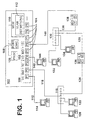
  • Referring now to Figure 1, a block diagram is shown of a network system 100 including a multiple port network device 102 implemented according to the present invention, which has a plurality of ports 104 labeled P1, P2, P3, ... Pn. The network device 102 may have as many ports 104 as desired, where each port 104 operates according to any type of network protocol, such as Ethernet or the like. Also, the ports 104 may include some ports operating according to one protocol and others operation according to a different protocol. For example, several of the ports 104 may operate at 10 megabits per second (Mbps) according to Ethernet 10Base-T while the remaining ports operate at 100 Mbps according to Ethernet 100Base-TX. The ports 104 enable connection of the network device 102 to a plurality of other network devices through network segments, such as twisted-pair cables, fiber optic cables, coaxial cables, etc. or even wireless connections as known to those skilled in the art. The other network devices include bridges, switches, repeaters, routers, brouters, etc., or any type of Data Terminal Equipment (DTE) device, which is any source or destination of data including a computer system with a network interface card (NIC) or the like.
    The network device 102 is preferably a multiple port bridge or switch, which includes processing logic or a processor 106, port circuitry 108 and memory 110, which includes any combination of non-volatile and programmable memory, such as read only memory (ROM), random access memory (RAM), etc. The processor 106, the port circuitry 108 and the memory 110 may be implemented and coupled in any desired manner. For example, the memory 110 may be a central memory and coupled to both the processor 106 and the port circuitry 108 as desired, or the memory 110 is distributed within the network device 102, such as separate memory modules for the processor 106, the port circuitry 108 and even for any one or more of the individual ports P1-Pn.
    The processor 106 generally performs the processing functions and procedures including initialization and configuration of the network switch 102. The processor 106 executes routines stored the memory 110 for performing its various functions. For example, the processor 106 performs the spanning tree functions according to the ANSI/IEEE Std. 802.1D standard, including initialization procedures according to section 4.7.1 and spanning tree configuration according to section 4.8.1. The processor 106 also performs ongoing management functions during operation, including dynamically reconfiguration of virtual LAN (VLAN) definitions according to the present invention as described more fully below. The port circuitry 108 is coupled to each of the ports 104 for controlling packet data flow between the ports 104 and for enabling the processor 106 to control operation of the ports 104 as desired.
    The memory 110 includes a programmable VLAN definition section 112 for defining any grouping of the ports 104 as desired. The processor 106 executes routines for assisting a user or system administrator to program the memory 110. As shown in Figure 1, at least two separate VLANs are defined, including a VLAN V1 150 including ports P1, P2 and P3, and a VLAN V2 152 including ports P4, P5 and P6. Thus, the VLANs V1 and V2 include mutually-exclusive sets of the ports 104. In the preferred embodiment, the VLAN definition section 112 includes a VLAN port mask for each port, where each port mask includes a bit for every port of the network device 102. A bit in the port mask is set to a logic high level (such as logic one) to include the respective port in a VLAN and cleared to a logic low level (such as logic zero) to mask the port. In this manner, each port
    Figure 00080001
    s port mask defines a VLAN for that port by identifying every other port 104 belonging in the same VLAN group. Of course, each port 104 may be defined as its own VLAN, or all of the ports 104 may be included in one global VLAN.
    A network segment 112 couples a DTE device 114 to port P1. A network segment 116 couples a network device 118 to port P2. The network device 118 is preferably a repeater or the like with multiple ports for coupling one or more DTE devices 120, 122 via separate network segments. One port of the repeater 118 is coupled to one port of another network device 126 through a network segment 124. The network device 126 is a bridge, which includes another port coupled to another repeater 130 via a network segment 128. The repeater 130 couples one or more DTE devices 132, 134 through separate network segments, and is coupled to one port of another bridge 138 via a network segment 136. The bridge 138 includes another port coupled to port P6 of the network device 102 via a network segment 140. A DTE device 144 is coupled to port P4 through a network segment 142. The configuration shown in Figure 1 illustrates a hardware loop between ports P2 and P6 of the network device 102, where the hardware loop includes the devices 118, 126, 130 and 138 and the network segments 116, 124, 128, 136 and 140.
    Figure 2 is a simplified block diagram illustrating the network device 102 with a different VLAN definition. In particular, a first VLAN V1 202 includes ports P1, P2 and P3 and a second VLAN V2 204 includes ports P1-P6. In this manner, V1 is a subset of V2. A subset VLAN definition may cause problems if any of the shared ports P1, P2 or P3 are configured as blocking for one VLAN and non-blocking (listening/learning/forwarding) for another. For each port 104 and for each VLAN definition, the network device 102 determines a port status based on user-defined parameters and the results of the spanning tree operation. If a port is blocked, then the network device 102 generally ignores any data packets received at the port and does not send any data packets via that port. A port is set to a listening status mode during configuration to send and receive configuration packets, otherwise known as bridge protocol data units (BPDUs). A port is set to a learning status mode to perform the learning bridge functions of examining and storing network addresses of devices coupled to the port. A port is set to a forwarding mode for sending and receiving data packets.
    Figure 3 is another simplified block diagram of the network device 102 with another VLAN definition, where a VLAN V1 302 includes ports P1-P4 and a VLAN V2 304 includes ports P4-P7. In this manner, port P4 is shared between both VLANs V1 and V2. Ports P2 and P5 are coupled to an external network 306, which includes a bridge device 308 with a simplified bridge identifier (ID) of 5. Normally, each bridging device is assigned at least one bridge ID (or BID in the Figures), which is an industry-wide, 48-bit unique address. The network switch 102 has assigned a bridge ID of 12 to VLAN V1 and a bridge ID of 13 to V2. If the bridge ID of 5 of the bridge device 308 is the lowest according to the spanning tree procedure, then the bridge device 308 is the ROOT bridge for the network 306 including the network device 102. Port P2 becomes the ROOT port for the VLAN V1 and port P5 becomes the ROOT port for the VLAN V2 of the network device 102. Since V1 and V2 have a shared port and different root ports, a loop exists across the VLANs V1 and V2, which further causes potential problems, such as duplicate packets, address conflicts, broadcast storms, etc.
    Figure 4 is another simplified block diagram of the network device 102 with the same VLAN definition shown in Figure 3, where V1 includes ports P1-P4 and V2 includes ports P4-P7. However, the network system 306 is coupled to the shared port P4. Thus, port P4 becomes the ROOT port for both VLANs V1 and V2.
    Figure 5 is another simplified block diagram of the network device 102 with another VLAN definition, where a VLAN V1 502 includes ports P1-P5 and a VLAN V2 504 includes ports P3-P7. In this case, the ports P3-P5 are shared among the VLANs V1 and V2. After initialization and configuration, port P3 is determined to be the ROOT port for both V1 and V2. Port P4 is configured as blocking for both V1 and V2 as shown with an "X" symbol therein. However, port P5 is set to blocking for V1 and forwarding for V2. Although it is generally allowed that two or more ports be shared among several VLANs, network problems arise if a shared port is blocking for one VLAN and not blocking for any other one of the sharing VLANs.
    Figure 6 is another simplified block diagram of the network device 102 yet with another VLAN definition, where a VLAN V1 602 includes ports P2-P4, a VLAN V2 604 includes ports P3-P7 and a VLAN V3 606 includes ports P4, P8 and P9. In this manner, port P3 is shared between VLANs V1 and V2, and port P4 is shared between all three VLANs V1-V3. In general, such multiple port sharing is allowed, but may cause problems as previously described with configurations according to the standard spanning tree procedure. For example, address conflict and/or duplicate packet problems arise if port P3 is blocking for V1 and forwarding for V2.
    Figure 7 is a flowchart diagram illustrating a reconfiguration procedure performed by the network device 102 to overcome any of the VLAN configuration problems described above. The reconfiguration procedure modifies the user-defined VLAN definitions, as performed by the processor 106; the port circuitry 108, or any combination thereof. At a first step 702, the VLAN assignments are read from the memory 110, such as defined in the VLAN definition section 112. At next step 704, any equivalent VLANs are merged together, where equivalent VLANs are those having the same port assignments. Also, any subset VLANs are merged together with their corresponding superset VLANs. Two VLANs Vi and Vj are merged according to the following equations (1) and (2): Vi' (fwd_mask) := Vi (fwd_mask) OR Vj (fwd_mask) Vj' (fwd_mask) := Vj (fwd_mask) OR Vi (fwd_mask) where fwd_mask denotes the port mask of the indicated VLAN, the VLANs Vi' and Vj' are the "new" VLAN definitions, the ":=" operator means "set equal to", and the "OR" operator is the logic OR bit-wise operation. As indicated by the equations (1) and (2), the new VLAN definitions are the same for both new VLANs, and includes a superset of the ports of the original VLAN definitions. Once merged, only one of the VLAN assignments is active and used for purposes of determining the spanning tree, while the other VLAN definition is kept in the management information base (MIB) of the network device 102 for management purposes, but is not used for purposes of determining the spanning tree. The port mask assignments of each of the affected ports is modified in the VLAN definitions 112, where the new VLAN port mask definition is used for each affected and included port. It is also noted that the original VLAN definitions are also kept for purposes of network management.
    Using Figure 2 as an example, V1 has a port mask fwd_mask = 000007h (where "h" denotes hexadecimal notation) and V2 has a port mask fwd_mask = 00003Fh. After the merge operation, the port masks for both of the new VLANs V1' and V2' is fwd_mask = 00003Fh. The new port mask definition V1' is active and used for purposes of the spanning tree, and the "new" port mask definition for V2' is kept for purposes of management, marked as a merged VLAN, but is not active and thus is not used for determining the spanning tree. The port masks for each of the ports P1-P6 are also set equal to the new fwd_mask = 00003Fh.
    At next step 706, the network device 102 assigns a unique bridge ID for each active VLAN. At next step 708, each port of each active VLAN is initialized according to the spanning tree initialization procedure as defined in section 4.8.1 of ANSI/IEEE Std. 802.1D. At next step 710, the spanning tree configuration procedure as defined in section 4.7.1 of ANSI/IEEE Std. 802.1D is performed for each port of each active VLAN. After the configuration procedure according to the standard spanning tree procedure, each VLAN has been assigned a root identifier (ROOT ID) and a ROOT port. For example, as shown in Figure 3, the VLAN V1 is assigned a ROOT ID of 5 and port 2 is its ROOT port, and the VLAN V2 is assigned a ROOT ID of 5 and port 5 is its ROOT port.
    At next steps 712 and 714, each active VLAN is compared with every other VLAN to identify any potential network problems as previously described. Any problematic pair of VLANs are merged into a new VLAN definition as described below, and the new VLAN is then compared with every remaining VLAN until all remaining and active VLANs have been tested and configured. At step 714, a new pair of active VLANs are selected. At next step 716, the ROOT ID of the selected VLANs are compared. If the ROOT IDs of the selected pair are not equal, operation returns to step 712 to select another pair of active VLANs. In the case of unequal ROOT IDs, the two VLANs are not linked together and contains no problematic loops, and thus the spanning tree is satisfactory. If, however, the ROOT IDs of the selected pair are equal, operation proceeds to step 718, where it is queried whether the ROOT ports of the selected pair are equal. If the ROOT IDs of the selected pair are equal but the ROOT ports are not, as illustrated in Figure 3, operation proceeds to step 722 to merge the two VLANs.
    The equations (1) and (2) provided above are used to merge the two VLANs in step 722. For example, as shown in Figure 3, the VLAN V1 has a port mask fwd_mask = 00000Fh and the VLAN V2 has a port mask fwd_mask = 000078h. Each of the new VLANs V1' and V2' have a new port mask fwd_mask = 00007Fh as a result of the merge operation. As described above, the VLAN V1' is selected for continued spanning tree operations and the VLAN V2' is marked as merged and not used. The port mask definitions for each of the ports P1-P7 are modified and set equal to 00007Fh, and the resulting VLAN V1' 802 is shown in Figure 8. At next step 724, a bridge ID is assigned for the new VLAN V1', which may be a completely new bridge ID or one of the bridge IDs assigned to the original VLANs V1 and V2. As shown in Figure 8, the new VLAN V1' is assigned the bridge ID = 12 of the original VLAN V1. At next step 726, all of the ports of the new VLAN are initialized in a similar manner as described for step 708, and the spanning tree configuration for the new VLAN is performed in a similar manner as described for step 710.
    As shown in Figure 8, the new configuration for the new VLAN V1' results in one of the ROOT ports to be selected as the ROOT port for the new VLAN V1' 802, since only one ROOT port may be selected for any given VLAN. From step 728, operation returns to step 712 to compare another pair of VLANs, where the new VLAN is also eventually compared with every other VLAN. Referring back to step 718, if the ROOT IDs and the ROOT ports are equal, such as shown in Figures 4 and 5, operation proceeds to step 720. At step 720, it is queried whether any shared port is blocked for one VLAN and not for any other VLAN. If not, such as shown in Figure 4, then operation returns to step 712 to select another pair of VLANs for comparison. If, however, a shared port is blocked for one VLAN and not for another, such as the port P5 of the configuration shown in Figure 5, then operation proceeds to step 722 to merge the VLANs. For example, in Figure 5, the port P5 is blocked for VLAN V1 but is in the forwarding state for the VLAN V2. In this case, the VLANs V1 and V2 are merged resulting in a new VLAN V1' 902, as shown in Figure 9. After the initialization and configuration steps 726, 728 are performed, the ROOT port is likely to remain the same depending upon the bridge ID assigned to the new VLAN. The port originally having different status settings for different VLANs, which was the port P5 in Figure 5, is given a new status setting, such as forwarding, blocking, etc., for the new VLAN V1' shown in Figure 9.
    After all of the active VLANs and newly merged VLANs have been compared as determined in step 712, operation is complete for the original VLAN definition. In one embodiment, however, the VLAN definition may be modified during operation. If the VLAN definitions are reconfigured during operation, the procedure shown in Figure 7 is repeated for each new VLAN defined, and for each new VLAN as a result of merged VLANs, if any.
    A bridge MIB (RFC 1493) for the network device 102 may be extended for management purposes as desired. The bridge MIB is preferably stored in the memory 110. The MIB extensions enables a user or network administrator to determine merged VLANs and reconfigure the VLAN definitions or make hardware modifications as desired. An example of possible MIB extensions are as follows:
  • 1. dot1dBase group base extensions, which include the bridge address, number of ports present in the bridge etc.
  • 2. dot1dStp group extensions to cover all the virtual bridges and their spanning trees.
  • 3. dot1dTp group for each virtual bridge
  • 4. dot1dStatic group extensions if Static addresses have to be configured on a VLAN basis.
  • An example VLAN Management MIB is as follows:
    Figure 00140001
    Figure 00150001
    Figure 00160001
    Figure 00170001
    It is now appreciated that a method and apparatus for dynamically reconfiguring virtual LANs of a network device prevents network problems, such as looping data packets, address conflicts and/or broadcast storms, caused by particular VLAN definitions and/or hardware configuration. Equivalent and subset VLANs are first combined since they could potentially cause network problems. The spanning tree procedure is then performed, including initialization and configuration. After the initial spanning tree procedure is performed, the VLANs are compared to identify problematic configurations. Mutually-exclusive VLANs with the same root identifier have been connected together externally forming a loop, so that the VLANs are merged. VLANs with shared ports having different root ports are also merged. VLANs with shared ports and the same root port are merged if any shared port is blocking for one VLAN and not the other. Such VLAN merging prevents network problems that are not addressed by the spanning tree procedure because of overlapping VLAN definitions and/or hardware configurations. Also, VLAN merging results in a working network without introducing new problems.
    Although a system and method according to the present invention has been described in connection with the preferred embodiment, it is not intended to be limited to the specific form set forth herein, but on the contrary, it is intended to cover such alternatives, modifications, and equivalents, as can be reasonably included within the spirit and scope of the invention as defined by the appended claims.

    Claims (14)

    1. A method of configuring virtual LANs of a multiple port bridging device, comprising the steps of:
      predefining a plurality of virtual LANs by grouping ports together for each predefined virtual LAN;
      performing a spanning tree procedure to determine a root identifier and a root port for each virtual LAN;
      comparing the root identifier of each virtual LAN with at least one other virtual LAN;
      if the root identifier of any two virtual LANs are equal, comparing the root ports of the two virtual LANs; and
      if the root identifiers are the same and if the root ports are different for any two virtual LANs, merging the two virtual LANs into a new virtual LAN.
    2. The method of claim 1, wherein said step of merging comprises the step of combining all of the ports of the two virtual LANs to form the new virtual LAN.
    3. The method of claim 1, prior to said step of performing a spanning tree procedure, further comprising the step of:
      merging any predefined virtual LANs that are equivalent; and
      merging any predefined virtual LANs that is a subset of a larger virtual LAN with the larger virtual LAN.
    4. The method of claim 1, after said step of merging, further comprising the step of:
      performing a spanning tree procedure for the new virtual LAN.
    5. The method of claim 4, further comprising the steps of:
      comparing the root identifier of the new virtual LAN with at least one other virtual LAN;
      if the root identifier of the new virtual LAN is the same as the root identifier of any other virtual LAN, comparing the root ports of the two virtual LANs; and
      if the root identifiers are the same and if the root ports are different for the two virtual LANs, merging the two virtual LANs into another new virtual LAN.
    6. The method of claim 4, further comprising the steps of:
      comparing the root identifier of the new virtual LAN with at least one other virtual LAN;
      if the root identifier of the new virtual LAN is the same as the root identifier of any other virtual LAN, comparing the root ports of the two virtual LANs;
      if the root identifiers and the root ports are the same for the two virtual LANs, determining if any shared port of the two virtual LANs is blocked for one of the two virtual LANs and not the other; and
      if a shared port of the two virtual LANs is blocked for one of the two virtual LANs and not the other, merging the two virtual LANs into another new virtual LAN.
    7. The method of claim 1, further comprising the steps of:
      if the root identifiers and the root ports are the same for any two virtual LANs, determining if any shared port of the two virtual LANs is blocked for one of the two virtual LANs and not the other; and
      if a shared port of the two virtual LANs is blocked for one of the two virtual LANs and not the other, merging the two virtual LANs into a new virtual LAN.
    8. A network device, comprising:
      a plurality of ports;
      a virtual LAN definition circuit that defines a plurality of virtual LANs of said plurality of ports;
      spanning tree circuitry coupled to said virtual LAN definition circuit that determines a spanning tree definition for each of said plurality of virtual LANs including determination of a root identifier and a root port; and
      processing circuitry coupled to said spanning tree circuitry and said virtual LAN definition circuit that compares said spanning tree definition of each of said plurality of virtual LANs with at least one other of said plurality of virtual LANs, and that merges any two virtual LANs if said root identifier of both of said any two virtual LANs are the same and if said root port of both of said two virtual LANs are not the same.
    9. The network device of claim 8, further comprising:
      said processing circuitry further merges said any two virtual LANs if said root identifier and said root port of both of said any two virtual LANs are the same and if a shared port between said any two virtual LANs is blocking for one and not blocking for the other.
    10. The network device of claim 8, further comprising:
      said processing circuitry merging said any two virtual LANs by determining a new virtual LAN that includes all the ports of both of said any two virtual LANs.
    11. The network device of claim 8, wherein said spanning tree circuitry comprises:
      a processor;
      memory coupled to said processor; and
      port circuitry coupled to said processor.
    12. The network device of claim 8, wherein said processing circuitry comprises a processor coupled to memory.
    13. The network device of claim 8, wherein said processing circuitry operates the network device as a network switch.
    14. A network system, comprising:
      a multiple port bridging device, comprising:
      a plurality of ports;
      a virtual LAN definition circuit that defines a plurality of virtual LANs of said plurality of ports;
      spanning tree circuitry coupled to said virtual LAN definition circuit that determines a spanning tree definition for each of said plurality of virtual LANs including determination of a root identifier and a root port; and
      processing circuitry coupled to said spanning tree circuitry and said virtual LAN definition circuit that compares said spanning tree definition of each of said plurality of virtual LANs with at least one other of said plurality of virtual LANs, and that merges any two virtual LANs if said root identifier of both of said any two virtual LANs are the same and if said root port of both of said two virtual LANs are not the same and if said root identifier and said root port of both of said any two virtual LANs are the same and if a shared port between said any two virtual LANs is blocking for one and not blocking for the other; and
      a plurality of network devices coupled to said multiple port bridging device through at least one of said plurality of ports.
    EP97309623A 1996-12-27 1997-11-28 Method and apparatus for dynamically reconfiguring virtual lans of a network device Withdrawn EP0851634A3 (en)

    Applications Claiming Priority (2)

    Application Number Priority Date Filing Date Title
    US775021 1996-12-27
    US08/775,021 US5878232A (en) 1996-12-27 1996-12-27 Dynamic reconfiguration of network device's virtual LANs using the root identifiers and root ports determined by a spanning tree procedure

    Publications (2)

    Publication Number Publication Date
    EP0851634A2 true EP0851634A2 (en) 1998-07-01
    EP0851634A3 EP0851634A3 (en) 1999-09-29

    Family

    ID=25103082

    Family Applications (1)

    Application Number Title Priority Date Filing Date
    EP97309623A Withdrawn EP0851634A3 (en) 1996-12-27 1997-11-28 Method and apparatus for dynamically reconfiguring virtual lans of a network device

    Country Status (3)

    Country Link
    US (1) US5878232A (en)
    EP (1) EP0851634A3 (en)
    JP (1) JP4002335B2 (en)

    Cited By (6)

    * Cited by examiner, † Cited by third party
    Publication number Priority date Publication date Assignee Title
    GB2410648A (en) * 2004-01-30 2005-08-03 Hewlett Packard Development Co Managing a network having multiple domains
    DE19929517B4 (en) * 1998-07-01 2008-05-08 National Semiconductor Corp.(N.D.Ges.D.Staates Delaware), Santa Clara Apparatus and method for mapping VLAN tags
    WO2009088467A1 (en) * 2008-01-07 2009-07-16 Commscope Inc. Of North Carolina Methods, systems and computer program products for provisioning vlan services in a network
    US7565435B2 (en) 2003-12-20 2009-07-21 Alcatel Lucent Method for obtaining the best connectivity achievable within virtual local area networks
    US7848264B1 (en) * 1997-12-24 2010-12-07 Cisco Technology, Inc. Method and apparatus for rapidly reconfiguring computer networks
    CN103200067A (en) * 2012-01-05 2013-07-10 通用电气公司 Dynamic virtual LANs to segregate data

    Families Citing this family (177)

    * Cited by examiner, † Cited by third party
    Publication number Priority date Publication date Assignee Title
    US6400681B1 (en) 1996-06-20 2002-06-04 Cisco Technology, Inc. Method and system for minimizing the connection set up time in high speed packet switching networks
    US5909682A (en) * 1996-12-30 1999-06-01 Mci Worldcom, Inc. Real-time device data management for managing access to data in a telecommunication system
    US6658526B2 (en) * 1997-03-12 2003-12-02 Storage Technology Corporation Network attached virtual data storage subsystem
    US6934249B1 (en) 1997-04-01 2005-08-23 Cisco Technology, Inc. Method and system for minimizing the connection set up time in high speed packet switching networks
    US6459700B1 (en) * 1997-06-23 2002-10-01 Compaq Computer Corporation Multiple segment network device configured for a stacked arrangement
    US6081522A (en) 1997-06-30 2000-06-27 Sun Microsystems, Inc. System and method for a multi-layer network element
    US6049528A (en) 1997-06-30 2000-04-11 Sun Microsystems, Inc. Trunking ethernet-compatible networks
    US6115378A (en) * 1997-06-30 2000-09-05 Sun Microsystems, Inc. Multi-layer distributed network element
    US6081512A (en) 1997-06-30 2000-06-27 Sun Microsystems, Inc. Spanning tree support in a high performance network device
    US6088356A (en) 1997-06-30 2000-07-11 Sun Microsystems, Inc. System and method for a multi-layer network element
    US6044087A (en) 1997-06-30 2000-03-28 Sun Microsystems, Inc. Interface for a highly integrated ethernet network element
    US6044418A (en) 1997-06-30 2000-03-28 Sun Microsystems, Inc. Method and apparatus for dynamically resizing queues utilizing programmable partition pointers
    US6246669B1 (en) 1997-11-28 2001-06-12 Cisco Technology, Inc. Method and system for optimizing connection set-up operations in a high speed digital network
    US6188694B1 (en) * 1997-12-23 2001-02-13 Cisco Technology, Inc. Shared spanning tree protocol
    US6032194A (en) 1997-12-24 2000-02-29 Cisco Technology, Inc. Method and apparatus for rapidly reconfiguring computer networks
    US6202114B1 (en) * 1997-12-31 2001-03-13 Cisco Technology, Inc. Spanning tree with fast link-failure convergence
    US6301224B1 (en) * 1998-01-13 2001-10-09 Enterasys Networks, Inc. Network switch with panic mode
    US6469987B1 (en) 1998-01-13 2002-10-22 Enterasys Networks, Inc. Virtual local area network with trunk stations
    US6112251A (en) 1998-01-13 2000-08-29 Cabletron Systems, Inc. Virtual local network for sending multicast transmissions to trunk stations
    US7027406B1 (en) * 1998-04-16 2006-04-11 Avaya Communication Israel Ltd. Distributed port-blocking method
    US6445691B2 (en) * 1998-06-08 2002-09-03 Koninklijke Philips Electronics N. V. Wireless coupling of standardized networks and non-standardized nodes
    US6445690B2 (en) * 1998-06-08 2002-09-03 Koninklijke Philips Electronics N.V. Wireless coupling of incompatible nodes via a virtual network
    KR100298979B1 (en) * 1998-06-12 2001-09-06 윤종용 I Triple Triple 1394 Serial Bus Topology Optimization
    US6657959B1 (en) 1998-06-27 2003-12-02 Intel Corporation Systems and methods for implementing ABR with guaranteed MCR
    US6735773B1 (en) 1998-06-27 2004-05-11 Intel Corporation Method and apparatus for issuing commands to a network processor configured to provide a plurality of APIs
    US6604136B1 (en) 1998-06-27 2003-08-05 Intel Corporation Application programming interfaces and methods enabling a host to interface with a network processor
    US6724767B1 (en) * 1998-06-27 2004-04-20 Intel Corporation Two-dimensional queuing/de-queuing methods and systems for implementing the same
    US6603768B1 (en) 1998-06-27 2003-08-05 Intel Corporation Multi-protocol conversion assistance method and system for a network accelerator
    US6728249B2 (en) 1998-06-27 2004-04-27 Intel Corporation System and method for performing cut-through forwarding in an ATM network supporting LAN emulation
    US6246702B1 (en) * 1998-08-19 2001-06-12 Path 1 Network Technologies, Inc. Methods and apparatus for providing quality-of-service guarantees in computer networks
    US6215797B1 (en) 1998-08-19 2001-04-10 Path 1 Technologies, Inc. Methods and apparatus for providing quality of service guarantees in computer networks
    US20040208158A1 (en) 1998-08-19 2004-10-21 Fellman Ronald D. Methods and apparatus for providing quality-of-service guarantees in computer networks
    US6628661B1 (en) * 1998-08-27 2003-09-30 Intel Corporation Spanning tree recovery in computer networks
    US6765919B1 (en) * 1998-10-23 2004-07-20 Brocade Communications Systems, Inc. Method and system for creating and implementing zones within a fibre channel system
    JP3175826B2 (en) * 1998-11-24 2001-06-11 日本電気株式会社 Network configuration method and network management node
    US6898189B1 (en) 2000-08-23 2005-05-24 Cisco Technology, Inc. Restartable spanning tree for high availability network systems
    US6628624B1 (en) 1998-12-09 2003-09-30 Cisco Technology, Inc. Value-added features for the spanning tree protocol
    US6801506B1 (en) * 1999-03-31 2004-10-05 Cisco Technology, Inc. Method and apparatus for providing fast spanning tree re-starts
    US6526052B1 (en) 1998-12-23 2003-02-25 Enterasys Networks, Inc. Virtual local area networks having rules of precedence
    US6771610B1 (en) * 1999-01-19 2004-08-03 3Com Corporation Spanning tree with protocol for bypassing port state transition timers
    US6798739B1 (en) 1999-06-07 2004-09-28 Nortel Networks Limited Mechanism for splicing trees
    US6879594B1 (en) 1999-06-07 2005-04-12 Nortel Networks Limited System and method for loop avoidance in multi-protocol label switching
    US6724734B1 (en) 1999-06-15 2004-04-20 Avaya Communication Israel, Ltd. Creating a spanning tree of a network including clusters
    US6781953B1 (en) * 1999-08-03 2004-08-24 Avaya Communication Israel Ltd. Broadcast protocol for local area networks
    US6779016B1 (en) 1999-08-23 2004-08-17 Terraspring, Inc. Extensible computing system
    US8234650B1 (en) 1999-08-23 2012-07-31 Oracle America, Inc. Approach for allocating resources to an apparatus
    US7463648B1 (en) 1999-08-23 2008-12-09 Sun Microsystems, Inc. Approach for allocating resources to an apparatus based on optional resource requirements
    US8179809B1 (en) 1999-08-23 2012-05-15 Oracle America, Inc. Approach for allocating resources to an apparatus based on suspendable resource requirements
    US7703102B1 (en) 1999-08-23 2010-04-20 Oracle America, Inc. Approach for allocating resources to an apparatus based on preemptable resource requirements
    US8032634B1 (en) 1999-08-23 2011-10-04 Oracle America, Inc. Approach for allocating resources to an apparatus based on resource requirements
    US8019870B1 (en) 1999-08-23 2011-09-13 Oracle America, Inc. Approach for allocating resources to an apparatus based on alternative resource requirements
    JP4481401B2 (en) * 1999-10-08 2010-06-16 富士通マイクロエレクトロニクス株式会社 Network control method and apparatus
    US6678241B1 (en) 1999-11-30 2004-01-13 Cisc Technology, Inc. Fast convergence with topology switching
    US6658012B1 (en) 2000-04-27 2003-12-02 International Business Machines Corporation Statistics for VLAN bridging devices
    US7594028B1 (en) 2000-04-28 2009-09-22 International Business Machines Corporation Counting of GVRP protocol data units within a network bridge
    JP2001352335A (en) 2000-06-07 2001-12-21 Nec Corp Lan duplicate system and lan duplication method used for it
    US6934262B1 (en) * 2000-08-26 2005-08-23 Cisco Technology, Inc. Method and apparatus for restricting the assignment of VLANs
    US6937576B1 (en) 2000-10-17 2005-08-30 Cisco Technology, Inc. Multiple instance spanning tree protocol
    US7000011B1 (en) * 2000-11-06 2006-02-14 Hewlett-Packard Development Company, Lp. Designing interconnect fabrics
    US6839793B2 (en) * 2001-03-28 2005-01-04 Intel Corporation Method and apparatus to maximize bandwidth availability to USB devices
    US7366194B2 (en) 2001-04-18 2008-04-29 Brocade Communications Systems, Inc. Fibre channel zoning by logical unit number in hardware
    US7698389B2 (en) * 2001-05-16 2010-04-13 Hewlett-Packard Development Company, L.P. Device configuration in a distributed environment
    US7099285B1 (en) * 2001-06-15 2006-08-29 Advanced Micro Devices, Inc. Remote configuration of a subnet configuration table in a network device
    US7441017B2 (en) * 2001-06-29 2008-10-21 Thomas Lee Watson System and method for router virtual networking
    US20030041238A1 (en) * 2001-08-15 2003-02-27 International Business Machines Corporation Method and system for managing resources using geographic location information within a network management framework
    US7177946B1 (en) 2001-12-06 2007-02-13 Cisco Technology, Inc. Optimal sync for rapid spanning tree protocol
    US7433948B2 (en) * 2002-01-23 2008-10-07 Cisco Technology, Inc. Methods and apparatus for implementing virtualization of storage within a storage area network
    US7088674B2 (en) * 2001-12-27 2006-08-08 Alcatel Canada Inc. Method and apparatus for checking continuity of leaf-to-root VLAN connections
    US20030145294A1 (en) 2002-01-25 2003-07-31 Ward Julie Ann Verifying interconnect fabric designs
    US6963932B2 (en) * 2002-01-30 2005-11-08 Intel Corporation Intermediate driver having a fail-over function for a virtual network interface card in a system utilizing Infiniband architecture
    US9009004B2 (en) * 2002-01-31 2015-04-14 Hewlett-Packasrd Development Comany, L.P. Generating interconnect fabric requirements
    US7532604B2 (en) * 2002-05-08 2009-05-12 Siemens Canada Limited Local area network with wireless client freedom of movement
    US20030227878A1 (en) * 2002-06-07 2003-12-11 Krumm-Heller Alexander Michael Apparatus and method for automatically and dynamically reconfiguring network provisioning
    US20040042416A1 (en) * 2002-08-27 2004-03-04 Ngo Chuong Ngoc Virtual Local Area Network auto-discovery methods
    US7680086B2 (en) * 2002-09-09 2010-03-16 Siemens Canada Limited Wireless local area network with clients having extended freedom of movement
    US20040202185A1 (en) * 2003-04-14 2004-10-14 International Business Machines Corporation Multiple virtual local area network support for shared network adapters
    US7508774B2 (en) * 2003-04-28 2009-03-24 Alcatel-Lucent Usa Inc. Extensions to the spanning tree protocol
    US7352740B2 (en) * 2003-04-29 2008-04-01 Brocade Communciations Systems, Inc. Extent-based fibre channel zoning in hardware
    US7034837B2 (en) * 2003-05-05 2006-04-25 Silicon Graphics, Inc. Method, system, and computer program product for determining a structure of a graphics compositor tree
    US7627654B2 (en) 2003-06-09 2009-12-01 Foundry Networks, Inc. System and method for multiple spanning tree protocol domains in a virtual local area network
    US7564858B1 (en) 2003-08-01 2009-07-21 Foundry Networks, Inc. System and method for enabling a remote instance of a loop avoidance protocol
    US7558205B1 (en) * 2003-08-01 2009-07-07 Foundry Networks, Inc. System and method for detecting and isolating a remote loop
    US7734736B2 (en) * 2003-08-19 2010-06-08 Alcatel Lucent Configuring virtual LANs on layer 2
    CN1317864C (en) * 2003-09-13 2007-05-23 华为技术有限公司 A method for implementing table update in virtual local area network
    WO2005057863A1 (en) * 2003-12-12 2005-06-23 Fujitsu Limited Data transmission apparatus
    US7430203B2 (en) * 2004-01-29 2008-09-30 Brocade Communications Systems, Inc. Fibre channel zoning hardware for directing a data packet to an external processing device
    US7774461B2 (en) 2004-02-18 2010-08-10 Fortinet, Inc. Mechanism for determining a congestion metric for a path in a network
    US7275151B2 (en) * 2004-06-03 2007-09-25 International Business Machines Corporation Nodelay per port
    JP2006033275A (en) * 2004-07-14 2006-02-02 Fujitsu Ltd Loop frame detector and loop frame detection method
    US7701881B1 (en) * 2004-07-17 2010-04-20 Cisco Technology, Inc. System and method for determining the mergeability of spanning tree instances
    FR2882939B1 (en) * 2005-03-11 2007-06-08 Centre Nat Rech Scient FLUIDIC SEPARATION DEVICE
    JP4503470B2 (en) * 2005-03-17 2010-07-14 富士通株式会社 Server management apparatus and computer server
    US7150689B2 (en) * 2005-03-21 2006-12-19 Balingit Ronald F Pitching practice apparatus
    US8260932B2 (en) * 2005-04-27 2012-09-04 International Business Machines Corporation Using broadcast domains to manage virtual local area networks
    JP4580865B2 (en) * 2005-11-30 2010-11-17 株式会社東芝 Telephone system and channel acquisition method of the telephone system
    CN101051924B (en) * 2006-04-06 2011-05-18 华为技术有限公司 Equipment managing method for user's networks and user's network managing entity
    US20080034167A1 (en) * 2006-08-03 2008-02-07 Cisco Technology, Inc. Processing a SCSI reserve in a network implementing network-based virtualization
    US8614954B2 (en) * 2006-10-26 2013-12-24 Hewlett-Packard Development Company, L.P. Network path identification
    US7995499B2 (en) * 2006-11-23 2011-08-09 Cisco Technology, Inc. Minimizing spanning-tree protocol event processing and flooding in distribution networks
    CN101299671B (en) * 2007-04-30 2013-03-13 上海贝尔阿尔卡特股份有限公司 Method and device for transmitting and receiving multicast data packet
    GB2462981B (en) * 2007-06-19 2012-03-07 Commscope Inc Methods,systems, and computer program products for using managed port circuitry to map connections among structured cabling apparatus and network devices
    US8681641B1 (en) * 2007-06-25 2014-03-25 Cisco Technology, Inc. Loop mitigation mechanism for ethernet networks
    US8077709B2 (en) 2007-09-19 2011-12-13 Cisco Technology, Inc. Redundancy at a virtual provider edge node that faces a tunneling protocol core network for virtual private local area network (LAN) service (VPLS)
    JP4417997B2 (en) * 2007-12-13 2010-02-17 株式会社東芝 Overlay network system, overlay network construction and maintenance method in the same system, and program
    US9274851B2 (en) * 2009-11-25 2016-03-01 Brocade Communications Systems, Inc. Core-trunking across cores on physically separated processors allocated to a virtual machine based on configuration information including context information for virtual machines
    US8769155B2 (en) * 2010-03-19 2014-07-01 Brocade Communications Systems, Inc. Techniques for synchronizing application object instances
    US20110228772A1 (en) 2010-03-19 2011-09-22 Brocade Communications Systems, Inc. Providing multicast services without interruption upon a switchover
    US9461840B2 (en) 2010-06-02 2016-10-04 Brocade Communications Systems, Inc. Port profile management for virtual cluster switching
    US8989186B2 (en) 2010-06-08 2015-03-24 Brocade Communication Systems, Inc. Virtual port grouping for virtual cluster switching
    US9001824B2 (en) 2010-05-18 2015-04-07 Brocade Communication Systems, Inc. Fabric formation for virtual cluster switching
    US8867552B2 (en) 2010-05-03 2014-10-21 Brocade Communications Systems, Inc. Virtual cluster switching
    US9716672B2 (en) 2010-05-28 2017-07-25 Brocade Communications Systems, Inc. Distributed configuration management for virtual cluster switching
    US9769016B2 (en) 2010-06-07 2017-09-19 Brocade Communications Systems, Inc. Advanced link tracking for virtual cluster switching
    US9270486B2 (en) 2010-06-07 2016-02-23 Brocade Communications Systems, Inc. Name services for virtual cluster switching
    US9608833B2 (en) 2010-06-08 2017-03-28 Brocade Communications Systems, Inc. Supporting multiple multicast trees in trill networks
    US9806906B2 (en) 2010-06-08 2017-10-31 Brocade Communications Systems, Inc. Flooding packets on a per-virtual-network basis
    US8446914B2 (en) 2010-06-08 2013-05-21 Brocade Communications Systems, Inc. Method and system for link aggregation across multiple switches
    US9246703B2 (en) 2010-06-08 2016-01-26 Brocade Communications Systems, Inc. Remote port mirroring
    US9628293B2 (en) 2010-06-08 2017-04-18 Brocade Communications Systems, Inc. Network layer multicasting in trill networks
    US9807031B2 (en) 2010-07-16 2017-10-31 Brocade Communications Systems, Inc. System and method for network configuration
    US9104619B2 (en) 2010-07-23 2015-08-11 Brocade Communications Systems, Inc. Persisting data across warm boots
    US8495418B2 (en) 2010-07-23 2013-07-23 Brocade Communications Systems, Inc. Achieving ultra-high availability using a single CPU
    US8650285B1 (en) 2011-03-22 2014-02-11 Cisco Technology, Inc. Prevention of looping and duplicate frame delivery in a network environment
    US9270572B2 (en) 2011-05-02 2016-02-23 Brocade Communications Systems Inc. Layer-3 support in TRILL networks
    US9363207B2 (en) * 2011-06-24 2016-06-07 Cisco Technology, Inc. Private virtual local area network isolation
    US8948056B2 (en) * 2011-06-28 2015-02-03 Brocade Communication Systems, Inc. Spanning-tree based loop detection for an ethernet fabric switch
    US9401861B2 (en) 2011-06-28 2016-07-26 Brocade Communications Systems, Inc. Scalable MAC address distribution in an Ethernet fabric switch
    US9736085B2 (en) 2011-08-29 2017-08-15 Brocade Communications Systems, Inc. End-to end lossless Ethernet in Ethernet fabric
    US9143335B2 (en) 2011-09-16 2015-09-22 Brocade Communications Systems, Inc. Multicast route cache system
    US9699117B2 (en) 2011-11-08 2017-07-04 Brocade Communications Systems, Inc. Integrated fibre channel support in an ethernet fabric switch
    US9450870B2 (en) 2011-11-10 2016-09-20 Brocade Communications Systems, Inc. System and method for flow management in software-defined networks
    US8995272B2 (en) 2012-01-26 2015-03-31 Brocade Communication Systems, Inc. Link aggregation in software-defined networks
    US9742693B2 (en) 2012-02-27 2017-08-22 Brocade Communications Systems, Inc. Dynamic service insertion in a fabric switch
    US8892696B1 (en) * 2012-03-08 2014-11-18 Juniper Networks, Inc. Methods and apparatus for automatic configuration of virtual local area network on a switch device
    US9154416B2 (en) 2012-03-22 2015-10-06 Brocade Communications Systems, Inc. Overlay tunnel in a fabric switch
    US9374301B2 (en) 2012-05-18 2016-06-21 Brocade Communications Systems, Inc. Network feedback in software-defined networks
    US10277464B2 (en) 2012-05-22 2019-04-30 Arris Enterprises Llc Client auto-configuration in a multi-switch link aggregation
    EP2853066B1 (en) 2012-05-23 2017-02-22 Brocade Communications Systems, Inc. Layer-3 overlay gateways
    US9602430B2 (en) 2012-08-21 2017-03-21 Brocade Communications Systems, Inc. Global VLANs for fabric switches
    US10581763B2 (en) 2012-09-21 2020-03-03 Avago Technologies International Sales Pte. Limited High availability application messaging layer
    US9203690B2 (en) 2012-09-24 2015-12-01 Brocade Communications Systems, Inc. Role based multicast messaging infrastructure
    US9967106B2 (en) 2012-09-24 2018-05-08 Brocade Communications Systems LLC Role based multicast messaging infrastructure
    US9401872B2 (en) 2012-11-16 2016-07-26 Brocade Communications Systems, Inc. Virtual link aggregations across multiple fabric switches
    US9548926B2 (en) 2013-01-11 2017-01-17 Brocade Communications Systems, Inc. Multicast traffic load balancing over virtual link aggregation
    US9413691B2 (en) 2013-01-11 2016-08-09 Brocade Communications Systems, Inc. MAC address synchronization in a fabric switch
    US9350680B2 (en) 2013-01-11 2016-05-24 Brocade Communications Systems, Inc. Protection switching over a virtual link aggregation
    US9565113B2 (en) 2013-01-15 2017-02-07 Brocade Communications Systems, Inc. Adaptive link aggregation and virtual link aggregation
    US10616049B2 (en) 2013-01-25 2020-04-07 Dell Products, L.P. System and method for determining the configuration of switches in virtual link trunking environments
    US9407500B2 (en) 2013-01-25 2016-08-02 Dell Products L.P. System and method for determining the configuration of switches in virtual link trunking environments
    US9565099B2 (en) 2013-03-01 2017-02-07 Brocade Communications Systems, Inc. Spanning tree in fabric switches
    US9401818B2 (en) 2013-03-15 2016-07-26 Brocade Communications Systems, Inc. Scalable gateways for a fabric switch
    US9699001B2 (en) 2013-06-10 2017-07-04 Brocade Communications Systems, Inc. Scalable and segregated network virtualization
    US9565028B2 (en) 2013-06-10 2017-02-07 Brocade Communications Systems, Inc. Ingress switch multicast distribution in a fabric switch
    US9806949B2 (en) 2013-09-06 2017-10-31 Brocade Communications Systems, Inc. Transparent interconnection of Ethernet fabric switches
    US9912612B2 (en) 2013-10-28 2018-03-06 Brocade Communications Systems LLC Extended ethernet fabric switches
    US9548873B2 (en) 2014-02-10 2017-01-17 Brocade Communications Systems, Inc. Virtual extensible LAN tunnel keepalives
    US10581758B2 (en) 2014-03-19 2020-03-03 Avago Technologies International Sales Pte. Limited Distributed hot standby links for vLAG
    US10476698B2 (en) 2014-03-20 2019-11-12 Avago Technologies International Sales Pte. Limited Redundent virtual link aggregation group
    US10063473B2 (en) 2014-04-30 2018-08-28 Brocade Communications Systems LLC Method and system for facilitating switch virtualization in a network of interconnected switches
    US9800471B2 (en) 2014-05-13 2017-10-24 Brocade Communications Systems, Inc. Network extension groups of global VLANs in a fabric switch
    US10616108B2 (en) 2014-07-29 2020-04-07 Avago Technologies International Sales Pte. Limited Scalable MAC address virtualization
    US9544219B2 (en) 2014-07-31 2017-01-10 Brocade Communications Systems, Inc. Global VLAN services
    US9807007B2 (en) 2014-08-11 2017-10-31 Brocade Communications Systems, Inc. Progressive MAC address learning
    US9524173B2 (en) 2014-10-09 2016-12-20 Brocade Communications Systems, Inc. Fast reboot for a switch
    US9699029B2 (en) 2014-10-10 2017-07-04 Brocade Communications Systems, Inc. Distributed configuration management in a switch group
    US9619349B2 (en) 2014-10-14 2017-04-11 Brocade Communications Systems, Inc. Biasing active-standby determination
    US9628407B2 (en) 2014-12-31 2017-04-18 Brocade Communications Systems, Inc. Multiple software versions in a switch group
    US9626255B2 (en) 2014-12-31 2017-04-18 Brocade Communications Systems, Inc. Online restoration of a switch snapshot
    US10003552B2 (en) 2015-01-05 2018-06-19 Brocade Communications Systems, Llc. Distributed bidirectional forwarding detection protocol (D-BFD) for cluster of interconnected switches
    US9942097B2 (en) 2015-01-05 2018-04-10 Brocade Communications Systems LLC Power management in a network of interconnected switches
    US9807005B2 (en) 2015-03-17 2017-10-31 Brocade Communications Systems, Inc. Multi-fabric manager
    US10038592B2 (en) 2015-03-17 2018-07-31 Brocade Communications Systems LLC Identifier assignment to a new switch in a switch group
    US10579406B2 (en) 2015-04-08 2020-03-03 Avago Technologies International Sales Pte. Limited Dynamic orchestration of overlay tunnels
    US10439929B2 (en) 2015-07-31 2019-10-08 Avago Technologies International Sales Pte. Limited Graceful recovery of a multicast-enabled switch
    US10171303B2 (en) 2015-09-16 2019-01-01 Avago Technologies International Sales Pte. Limited IP-based interconnection of switches with a logical chassis
    US9912614B2 (en) 2015-12-07 2018-03-06 Brocade Communications Systems LLC Interconnection of switches based on hierarchical overlay tunneling
    US10237090B2 (en) 2016-10-28 2019-03-19 Avago Technologies International Sales Pte. Limited Rule-based network identifier mapping

    Citations (2)

    * Cited by examiner, † Cited by third party
    Publication number Priority date Publication date Assignee Title
    US5150360A (en) * 1990-03-07 1992-09-22 Digital Equipment Corporation Utilization of redundant links in bridged networks
    US5394402A (en) * 1993-06-17 1995-02-28 Ascom Timeplex Trading Ag Hub for segmented virtual local area network with shared media access

    Family Cites Families (13)

    * Cited by examiner, † Cited by third party
    Publication number Priority date Publication date Assignee Title
    US5079767A (en) * 1988-09-27 1992-01-07 Digital Equipment Corporation Method of multicast message distribution
    US5309437A (en) * 1990-06-29 1994-05-03 Digital Equipment Corporation Bridge-like internet protocol router
    US5398242A (en) * 1992-04-07 1995-03-14 Digital Equipment Corporation Automatically configuring LAN numbers
    US5490252A (en) * 1992-09-30 1996-02-06 Bay Networks Group, Inc. System having central processor for transmitting generic packets to another processor to be altered and transmitting altered packets back to central processor for routing
    US5430728A (en) * 1992-12-10 1995-07-04 Northern Telecom Limited Single-route broadcast for LAN interconnection
    US5734824A (en) * 1993-02-10 1998-03-31 Bay Networks, Inc. Apparatus and method for discovering a topology for local area networks connected via transparent bridges
    US5511168A (en) * 1993-07-01 1996-04-23 Digital Equipment Corporation Virtual circuit manager for multicast messaging
    JP3542159B2 (en) * 1994-03-17 2004-07-14 株式会社日立製作所 Bridge with multiprocessor structure
    EP0684716B1 (en) * 1994-05-25 2002-02-27 International Business Machines Corporation A data communication network and method for operating said network
    US5790808A (en) * 1995-07-06 1998-08-04 3 Com Active topology maintenance in reconfiguring bridged local area networks with state transition with forgetting interval
    US5684800A (en) * 1995-11-15 1997-11-04 Cabletron Systems, Inc. Method for establishing restricted broadcast groups in a switched network
    US5764636A (en) * 1996-03-28 1998-06-09 Cisco Technology, Inc. Color blocking logic mechanism for a high-performance network switch
    US5742604A (en) * 1996-03-28 1998-04-21 Cisco Systems, Inc. Interswitch link mechanism for connecting high-performance network switches

    Patent Citations (2)

    * Cited by examiner, † Cited by third party
    Publication number Priority date Publication date Assignee Title
    US5150360A (en) * 1990-03-07 1992-09-22 Digital Equipment Corporation Utilization of redundant links in bridged networks
    US5394402A (en) * 1993-06-17 1995-02-28 Ascom Timeplex Trading Ag Hub for segmented virtual local area network with shared media access

    Non-Patent Citations (1)

    * Cited by examiner, † Cited by third party
    Title
    HUANG N -F ET AL: "MOBILITY MANAGEMENT OF INTERCONNECTED VIRTUAL LANS OVER ATM NETWORKS" 1997 IEEE 47TH. VEHICULAR TECHNOLOGY CONFERENCE, PHOENIX, MAY 4 - 7, 1997, vol. 3, no. CONF. 47, 18 November 1996 (1996-11-18), pages 1156-1161, XP000741608 INSTITUTE OF ELECTRICAL AND ELECTRONICS ENGINEERSISBN: 0-7803-3660-7 *

    Cited By (12)

    * Cited by examiner, † Cited by third party
    Publication number Priority date Publication date Assignee Title
    US7848264B1 (en) * 1997-12-24 2010-12-07 Cisco Technology, Inc. Method and apparatus for rapidly reconfiguring computer networks
    DE19929517B4 (en) * 1998-07-01 2008-05-08 National Semiconductor Corp.(N.D.Ges.D.Staates Delaware), Santa Clara Apparatus and method for mapping VLAN tags
    US7565435B2 (en) 2003-12-20 2009-07-21 Alcatel Lucent Method for obtaining the best connectivity achievable within virtual local area networks
    GB2410648A (en) * 2004-01-30 2005-08-03 Hewlett Packard Development Co Managing a network having multiple domains
    GB2410648B (en) * 2004-01-30 2006-09-13 Hewlett Packard Development Co Method and system for managing a network having multiple domains
    US7706382B2 (en) 2004-01-30 2010-04-27 Hewlett-Packard Development Company, L.P. Method and system for managing a network having multiple domains
    WO2009088467A1 (en) * 2008-01-07 2009-07-16 Commscope Inc. Of North Carolina Methods, systems and computer program products for provisioning vlan services in a network
    GB2469250A (en) * 2008-01-07 2010-10-06 Commscope Inc Methods,systems and computer program products for provisioning vlan services in a network
    GB2469250B (en) * 2008-01-07 2012-05-23 Commscope Inc Methods,systems and computer program products for provisioning vlan services in a network
    US8490161B2 (en) 2008-01-07 2013-07-16 Commscope Inc., Of North Carolina Methods, systems and computer program products for provisioning VLAN services in a network
    CN103200067A (en) * 2012-01-05 2013-07-10 通用电气公司 Dynamic virtual LANs to segregate data
    EP2618527A3 (en) * 2012-01-05 2015-01-14 General Electric Company Dynamic virtual LANs to segregate data

    Also Published As

    Publication number Publication date
    JPH10224382A (en) 1998-08-21
    JP4002335B2 (en) 2007-10-31
    US5878232A (en) 1999-03-02
    EP0851634A3 (en) 1999-09-29

    Similar Documents

    Publication Publication Date Title
    US5878232A (en) Dynamic reconfiguration of network device's virtual LANs using the root identifiers and root ports determined by a spanning tree procedure
    EP0841782B1 (en) Broadcast isolation and level 3 network switch
    US7385939B2 (en) Network management apparatus and method for determining the topology of a network
    US6345041B1 (en) Method and apparatus for automatic load-balancing on multisegment devices
    AU749880B2 (en) Virtual local area networks having rules of precedence
    US6944130B1 (en) Method and apparatus for determining a layer 2 path in a switched network
    Cisco Cisco IOS Commands
    Cisco Configuring Transparent Bridging
    Cisco Configuring Transparent Bridging
    Cisco Configuring Transparent Bridging
    Cisco Configuring Transparent Bridging
    Cisco Configuring Transparent Bridging
    Cisco Configuring Transparent Bridging
    Cisco Configuring Transparent Bridging
    Cisco Concepts
    Cisco Concepts
    Cisco Concepts
    Cisco Concepts
    Cisco Concepts
    Cisco Concepts
    Cisco Concepts
    Cisco Concepts
    Cisco Concepts
    Cisco Concepts
    Cisco Concepts

    Legal Events

    Date Code Title Description
    PUAI Public reference made under article 153(3) epc to a published international application that has entered the european phase

    Free format text: ORIGINAL CODE: 0009012

    AK Designated contracting states

    Kind code of ref document: A2

    Designated state(s): AT BE CH DE DK ES FI FR GB GR IE IT LI LU MC NL PT SE

    AX Request for extension of the european patent

    Free format text: AL;LT;LV;MK;RO;SI

    PUAL Search report despatched

    Free format text: ORIGINAL CODE: 0009013

    AK Designated contracting states

    Kind code of ref document: A3

    Designated state(s): AT BE CH DE DK ES FI FR GB GR IE IT LI LU MC NL PT SE

    AX Request for extension of the european patent

    Free format text: AL;LT;LV;MK;RO;SI

    AKX Designation fees paid
    REG Reference to a national code

    Ref country code: DE

    Ref legal event code: 8566

    STAA Information on the status of an ep patent application or granted ep patent

    Free format text: STATUS: THE APPLICATION IS DEEMED TO BE WITHDRAWN

    18D Application deemed to be withdrawn

    Effective date: 20000330