EP0851639A2 - QPSK modulated backscatter system - Google Patents
QPSK modulated backscatter system Download PDFInfo
- Publication number
- EP0851639A2 EP0851639A2 EP97310147A EP97310147A EP0851639A2 EP 0851639 A2 EP0851639 A2 EP 0851639A2 EP 97310147 A EP97310147 A EP 97310147A EP 97310147 A EP97310147 A EP 97310147A EP 0851639 A2 EP0851639 A2 EP 0851639A2
- Authority
- EP
- European Patent Office
- Prior art keywords
- signal
- subcarrier
- modulated
- interrogator
- tag
- Prior art date
- Legal status (The legal status is an assumption and is not a legal conclusion. Google has not performed a legal analysis and makes no representation as to the accuracy of the status listed.)
- Withdrawn
Links
Images


Classifications
-
- H—ELECTRICITY
- H04—ELECTRIC COMMUNICATION TECHNIQUE
- H04L—TRANSMISSION OF DIGITAL INFORMATION, e.g. TELEGRAPHIC COMMUNICATION
- H04L27/00—Modulated-carrier systems
- H04L27/18—Phase-modulated carrier systems, i.e. using phase-shift keying
- H04L27/22—Demodulator circuits; Receiver circuits
-
- G—PHYSICS
- G06—COMPUTING; CALCULATING OR COUNTING
- G06K—GRAPHICAL DATA READING; PRESENTATION OF DATA; RECORD CARRIERS; HANDLING RECORD CARRIERS
- G06K19/00—Record carriers for use with machines and with at least a part designed to carry digital markings
- G06K19/06—Record carriers for use with machines and with at least a part designed to carry digital markings characterised by the kind of the digital marking, e.g. shape, nature, code
- G06K19/067—Record carriers with conductive marks, printed circuits or semiconductor circuit elements, e.g. credit or identity cards also with resonating or responding marks without active components
- G06K19/07—Record carriers with conductive marks, printed circuits or semiconductor circuit elements, e.g. credit or identity cards also with resonating or responding marks without active components with integrated circuit chips
- G06K19/077—Constructional details, e.g. mounting of circuits in the carrier
- G06K19/07701—Constructional details, e.g. mounting of circuits in the carrier the record carrier comprising an interface suitable for human interaction
- G06K19/07703—Constructional details, e.g. mounting of circuits in the carrier the record carrier comprising an interface suitable for human interaction the interface being visual
-
- G—PHYSICS
- G06—COMPUTING; CALCULATING OR COUNTING
- G06K—GRAPHICAL DATA READING; PRESENTATION OF DATA; RECORD CARRIERS; HANDLING RECORD CARRIERS
- G06K7/00—Methods or arrangements for sensing record carriers, e.g. for reading patterns
- G06K7/0008—General problems related to the reading of electronic memory record carriers, independent of its reading method, e.g. power transfer
-
- G—PHYSICS
- G06—COMPUTING; CALCULATING OR COUNTING
- G06K—GRAPHICAL DATA READING; PRESENTATION OF DATA; RECORD CARRIERS; HANDLING RECORD CARRIERS
- G06K7/00—Methods or arrangements for sensing record carriers, e.g. for reading patterns
- G06K7/10—Methods or arrangements for sensing record carriers, e.g. for reading patterns by electromagnetic radiation, e.g. optical sensing; by corpuscular radiation
- G06K7/10009—Methods or arrangements for sensing record carriers, e.g. for reading patterns by electromagnetic radiation, e.g. optical sensing; by corpuscular radiation sensing by radiation using wavelengths larger than 0.1 mm, e.g. radio-waves or microwaves
- G06K7/10316—Methods or arrangements for sensing record carriers, e.g. for reading patterns by electromagnetic radiation, e.g. optical sensing; by corpuscular radiation sensing by radiation using wavelengths larger than 0.1 mm, e.g. radio-waves or microwaves using at least one antenna particularly designed for interrogating the wireless record carriers
- G06K7/10356—Methods or arrangements for sensing record carriers, e.g. for reading patterns by electromagnetic radiation, e.g. optical sensing; by corpuscular radiation sensing by radiation using wavelengths larger than 0.1 mm, e.g. radio-waves or microwaves using at least one antenna particularly designed for interrogating the wireless record carriers using a plurality of antennas, e.g. configurations including means to resolve interference between the plurality of antennas
-
- H—ELECTRICITY
- H04—ELECTRIC COMMUNICATION TECHNIQUE
- H04L—TRANSMISSION OF DIGITAL INFORMATION, e.g. TELEGRAPHIC COMMUNICATION
- H04L27/00—Modulated-carrier systems
- H04L27/18—Phase-modulated carrier systems, i.e. using phase-shift keying
- H04L27/20—Modulator circuits; Transmitter circuits
- H04L27/2032—Modulator circuits; Transmitter circuits for discrete phase modulation, e.g. in which the phase of the carrier is modulated in a nominally instantaneous manner
- H04L27/2035—Modulator circuits; Transmitter circuits for discrete phase modulation, e.g. in which the phase of the carrier is modulated in a nominally instantaneous manner using a single or unspecified number of carriers
- H04L27/2042—Modulator circuits; Transmitter circuits for discrete phase modulation, e.g. in which the phase of the carrier is modulated in a nominally instantaneous manner using a single or unspecified number of carriers with more than two phase states
-
- H—ELECTRICITY
- H04—ELECTRIC COMMUNICATION TECHNIQUE
- H04L—TRANSMISSION OF DIGITAL INFORMATION, e.g. TELEGRAPHIC COMMUNICATION
- H04L27/00—Modulated-carrier systems
- H04L27/18—Phase-modulated carrier systems, i.e. using phase-shift keying
- H04L27/22—Demodulator circuits; Receiver circuits
- H04L27/233—Demodulator circuits; Receiver circuits using non-coherent demodulation
- H04L27/2331—Demodulator circuits; Receiver circuits using non-coherent demodulation wherein the received signal is demodulated using one or more delayed versions of itself
Definitions
- This invention relates to wireless communication systems and, more particularly, to a wireless communication system using modulated backscatter technology.
- RFID systems are used for identification and/or tracking of equipment, inventory, or living things.
- RFID systems are radio communication systems that communicate between a radio transceiver, called an Interrogator, and a number of inexpensive devices called Tags or transponders.
- the Interrogator communicates to the Tags using modulated radio signals, and the Tags respond with modulated radio signals.
- the Interrogator first transmits an amplitude modulated signal to the Tag. Then, the Interrogator transmits a Continuous-Wave (CW) radio signal to the Tag.
- CW Continuous-Wave
- the Tag then modulates the CW signal using Modulated BackScattering (MBS) where the antenna is electrically switched, by the Tag's modulating signal, from being an absorber of RF radiation to being a reflector of RF radiation; thereby encoding the Tag's information onto the CW radio signal.
- MCS Modulated BackScattering
- the Interrogator demodulates the incoming modulated radio signal and decodes the Tag's information message.
- MBS systems typically utilize amplitude modulated techniques for communications from the Interrogator to the Tag.
- Prior art maintains the use of Frequency Shift Keying modulation techniques.
- Prior art also maintains baseband homodyne detection of the MBS signal at the interrogator; however baseband homodyne detection suffers from oscillator phase noise, large DC offsets, and mixer noise.
- a duplex radio communication system comprises an Interrogator which generates a radio signal to at least one remote Tag.
- the remote Tag receives the radio signal.
- the Tag then generates a subcarrier signal, and using Quadrature Phase Shift Keying (QPSK), modulates an information signal onto the subcarrier.
- QPSK Quadrature Phase Shift Keying
- a Backscatter Modulator using this modulated subcarrier, modulates the reflection of the radio signal, the reflected signal being a reflected modulated signal.
- the Interrogator receives and demodulates the reflected modulated signal to obtain the information signal.
- demodulation utilizes a homodyne detector.
- the Interrogator modulates an information signal onto the radio signal, transmits that modulated radio signal to the Tag, and the Tag demodulates that modulated radio signal to recover the information signal.
- higher order phase modulations are used to modulate an information signal onto the subcarrier.
- One class of RFID applications involves using RFID technology to read information from a Tag affixed to a container or pallet.
- the container is moved across the reading field of an Interrogator.
- the reading field is defined as that volume of space within which a successful communication can take place. While the Tag is in the reading field, the Interrogator and Tag must complete their information exchange before the Tag moves out of the field. Since the Tag is moving through the reading field, the RFID system has only a limited amount of time to successfully complete the transaction.
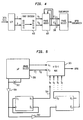
- FIG. 1 there is shown an overall block diagram of an illustrative RFID system useful for describing the application of the present invention.
- An Application Processor 101 communicates over Local Area Network (LAN) 102 to a plurality of Interrogators 103-104.
- the Interrogators may then each communicate with one or more of the Tags 105-107.
- the Interrogator 103 receives an information signal, typically from an Application Processor 101.
- the Interrogator 103 takes this information signal and Processor 200 (FIG. 2) properly formats a downlink message (Information Signal 200a) to be sent to the Tag.
- Processor 200 FIG. 2
- the information signal (200a) information such as information specifying which Tag is to respond (each Tag may have fixed or programmed identification number), instructions for the Tag's processor to execute or other information to be used and/or stored by the Tag's processor.
- Radio Signal Source 201 generates a radio signal
- the Modulator 202 modulates the Information Signal 200a onto the radio signal
- the Transmitter 203 sends this modulated signal via Antenna 204, illustratively using amplitude modulation, to a Tag.
- Amplitude modulation is a common choice since the Tag can demodulate such a signal with a single, inexpensive nonlinear device (such as a diode).
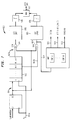
- the Antenna 301 receives the modulated signal.
- This signal is demodulated, directly to baseband, using the Detector/Modulator 302, which, illustratively, could be a single Schottky diode.
- the diode should be appropriately biased with a current level so that the impedance of the diode matches the impedance of the Antenna 301 such that losses of the radio signal are minimized.
- the result of the diode detector is essentially a demodulation of the incoming signal directly to baseband.
- the Information Signal 200a is then amplified, by Amplifier 303, and synchronization recovered in Clock and Frame Recovery Circuit 304.
- the Clock Recovery Circuit 304 can be enhanced by having the Interrogator send the amplitude modulated signal using Manchester encoding. If large amounts of data are being transferred in frames, frame synchronization may be implemented, for example, by detecting a predetermined bit pattern that indicates the start of a frame. The bit pattern may be detected by clock recovery circuit (304) or processor (305). Bit pattern detection is well known in the art. The resulting information is sent to a Processor 305.
- the Processor 305 is typically an inexpensive 4- or 8-bit microprocessor and its associated memory; the Clock Recovery Circuit 304 can be implemented in an ASIC (Applied Specific Integrated Circuit) which works together with Processor 305. This Processor 305 can also serve as the driver for an optional Display Unit 309 should this Tag require a display.
- the Processor 305 generates an Information Signal 306 based on the particular program being executed by processor 305.
- Signal 306 is eventually communicated from the Tag 105 back to the Interrogator (e.g., 103).
- This Information Signal 306 is sent to a Modulator Control Circuit 307, which uses the Information Signal 306 to modulate a subcarrier frequency generated by the subcarrier Frequency Source 308.
- the Frequency Source 308 could be a crystal oscillator separate from the Processor 305, or it could be a frequency source derived from signals present inside the Processor 305 - such as a divisor of the primary clock frequency of the Processor.
- the Modulated Subcarrier Signal 311 is used by Detector/Modulator 302 to modulate the modulated signal received from Tag 105 to produce a modulated backscatter (e.g., reflected) signal. This is accomplished by switching on and off the Schottky diode using the Modulated Subcarrier Signal 311, thereby changing the reflectance of Antenna 301.
- a Battery 310 or other power supply provides power to the circuitry of Tag 105. Power may also be received, for example, by using inductive coupling on microwaves.
- the Modulator Control Circuit 307 of the Tag generates an amplitude modulated signal modulated at an Information Signal 306 frequency ⁇ 2 . If the Radio Signal Source 201 generates a CW frequency ⁇ c , then the Interrogator receives signals at ⁇ c whose bandwidth is 2 ⁇ 2 and filters signals outside of this bandwidth range. This approach could be termed the "MBS at baseband" approach.
- the Tag to generate a subcarrier frequency ⁇ s , generated by Frequency Source 308, as shown in FIG. 3.
- the information could be conveyed using AM, FSK or Phase Shift Keying (PSK) by modulating the subcarrier with a frequency of ⁇ s with the Information Signal having a primary frequency ⁇ 2 306.
- the Interrogator receives signals at ⁇ c whose bandwidth is 2 ⁇ 2 but at a frequency ⁇ s away from ⁇ c . This method is termed "MBS of a subcarrier".
- BPSK Binary PSK
- QPSK Quadrature PSK
- MPSK Binary PSK
- DBPSK Differentially-encoded BPSK
- DQPSK Differentially-encoded QPSK
- the Tag When the Tag detects the presence of the Interrogator downlink signal it responds by transmitting its RFID data.
- the Tag differentially encodes the uplink data and uses the differentially encoded data to QPSK modulate the subcarrier.
- the QPSK modulated a subcarrier 311 modulates the reflected CW signal, which has a frequency ⁇ c by changing the reflectance of antenna 301 using signal 311.
- FIG. 4 shows the baseband encoding algorithm for DQPSK.
- the outputs, G I G Q of Gray encoder 410 are provided to phase adder 420.
- the information signal (306) is used to modulate the subcarrier which has a frequency ⁇ s (for example 250 kHz); the Modulated Subcarrier Signal 311 is used to control the reflectivity of the Detector Modulator 302 thereby sending a CW signal (having frequency ⁇ c ) that has been modulated by the DQPSK modulated subcarrier back to the Interrogator.
- the Interrogator receives signals at ⁇ c whose bandwidth is ⁇ 2 but at a frequency ⁇ s away from ⁇ c .
- the first method derives the subcarrier from the microprocessor crystal circuit (312) and is generated internally by the microprocessor 305.
- the DQPSK data is stored as a phase "word" inside the microprocessor memory.
- the word representing the current data bit is written to a external Port to produce 306 which controls the backscattering modulator 307.
- the word is shifted out the Port at twice the subcarrier frequency rate thereby producing the desired subcarrier frequency ⁇ s .
- an alternating 1.0 pattern is written to the port at a rate of 2 ⁇ s .
- the number of cycles in which the word is shifted out of the Port produces the desired channel symbol rate of the DQPSK modulated uplink signal. (This is half the channel symbol rate of BPSK and resulting in the channel bandwidth ⁇ 2 described above.)
- the second method for generating the modulated uplink is to generate the subcarrier frequency external to the microprocessor 305.
- a 4-to-1 multiplexor 503 is used as the QPSK modulator control 307.
- the multiplexor selects the phase of the subcarrier 311 by the current value of G I ' and G Q ', written to the select lines of the multiplexor from the processor port as signal 306.
- the subcarrier signal can be generated from the microprocessor's external crystal or clock circuit 312 by connecting a buffer circuit 501 and a digital clock divider circuit 502 (if necessary) to the microprocessor's clock circuit 312.
- the two O-flip-flops comprising clock divider circuit 502 produce the 4 phase shifts of the subcarrier signal 504 and multiplexor 503 selects one of the 4 phases based on the signals G I ' and G Q ' which are presented at multiplexor 503's select inputs.
- FIG. 6 illustrates the relationship between the output of buffer 501 and the outputs of the two O-flip-flops.
- the subcarrier signal 504 is phase modulated by the multiplexor circuit 503; thereby producing the second information signal.
- DMPSK requires that the data bits be Gray encoded M bits at a time and the digital clock divider will need additional stages to produce the M phase shifts of the subcarrier signal; an M-to-1 multiplexor is used as the modulator controller 307.
- the Interrogator 103 receives the reflected and modulated signal with the Receive Antenna 206, amplifies the signal with a Low Noise Amplifier 207, and demodulates the signal using homodyne detection in a Mixer 208 down to the Intermediate Frequency (IF) of the single subcarrier ⁇ s .
- IF Intermediate Frequency
- Radio Signal Source 201 as used in the transmit chain means the demodulation to IF is done using Homodyne detection; this has advantages in that it greatly reduces phase noise in the receiver circuits.
- the Mixer 208 then sends a Demodulated Signal 209 -- if using a Quadrature Mixer, it sends both I (in phase) and Q (quadrature) signals -- into Filter/Amplifier 210 to filter the Demodulated Signal 209.
- the resulting filtered signal -- then typically an Information Signal 211 carried on an IF subcarrier -- is then demodulated from the subcarrier in the Subcarrier Demodulator 212, which then sends the Information Signal 213 to Processor 200 to determine the content of the message.
- the I and Q channels of Signal 209 can be combined in the Filter/Amplifier 210, or in the Subcarrier Demodulator 212, or they could be combined in the Processor 200.
- DSP Digital Signal Processing
- the data recovery circuit 212 is implemented in Gate Array circuit, FIG. 6. It has two functions:
- the demodulator implements a Maximum A Posteriori (MAP) bit timing circuit.
- the demodulated data is sent to a bank of correlators 608, each of which is testing a different clock phase.
- the correlators measure the alignment of the input data with their clock over a B data bit window.
- the B bit window is 8 data bits long in this example; however, larger values of B are less sensitive to long strings of 1's or 0's, but require more hardware (or software/time) to implement.
- Each correlator is made from an integrate-and-dump filter, a weighting function that gives higher weight to high signal-to-noise data, and an accumulator (that accumulates over a period of B).
- a weighting function is not required, but it is possible to give higher weight to higher correlator outputs and lower weights to low correlator outputs. For example, correlator outputs approaching +1 or -1 are multiplied by a factor of 10, and correlator outputs approaching 0 are given a value equal to the square root of the actual output.
- the correlator with the highest accumulator value is found and its associated clock phase 609 is used to sample the next B bits of data. The accumulator is then reset, and the next B bits are examined. The important thing here is that there is no memory from one set of bits to the next; every B bits the clock estimation circuit generate a new estimate of the best clock phase that does not depend on previous estimates.
- Phase Locked Loop either analog or digital
- Phase Locked Loops have a minimum "lock-up" time that is a function of the loop filter. This lock-up time also increases as system noise increases and are unreliable for modest SNR.
- the largest correlator value is checked to see if it is higher than a fixed threshold. If it is, a signal is generated indicating that the bit clock is valid 610.
- the framing scheme uses a Barker code to indicate the start of the payload data. The presence of the Barker word is detected and generates a signal that indicates that the next bit is part of the payload 611.
- DMPSK requires additional shift register delay stages to produce the M phase shifts of the sampled modulated subcarrier signal and the additional XOR, accumulator and decision circuits to decode the M parallel bit paths.
- phase modulation schemes such as MSK (Minimum Shift Keyed), GMSK (Gaussian Minumum Shift Keyed), etc.
- MSK Minimum Shift Keyed
- GMSK Gaussian Minumum Shift Keyed
- pre-computed phase transitions could be stored in the processor's memory.
- the Tag can generate a smooth transition from one phase to another, and thereby produce an appropriately filtered phase modulation to produce a GMSK-modulated subcarrier.
- Other phase modulation schemes are also possible.
- an inexpensive, short-range, bi-directional digital radio communications channel is implemented.
- These techniques are inexpensive as the Tag components consist of (for example) a Schottky diode, an amplifier to boost the signal strength, bit and frame synchronization circuits, an inexpensive 4 or 8 bit microprocessor, subcarrier generation circuits, and a battery. Most of these items are already manufactured in large quantities for other applications, and thus are not overly expensive.
- the circuits mentioned above for subcarrier generation may also be implemented in logic surrounding the microprocessor core; thus, except for a relatively small amount of chip real estate, these functions come almost "for free.”
Abstract
Description
Claims (13)
- A modulated backscatter system, comprising:at least one transponder that receives a first transmitted signal and modulates a reflected first transmitted signal using a PSK modulated subcarrier; andat least one at least one interrogator having a transmitter that transmits said first transmitted signal and a receiver that receives said reflected first transmitted signal, said interrogator having a demodulator that obtains a received PSK modulated subcarrier signal from said reflected first transmitted signal, and a subcarrier demodulator that demodulates said received PSK modulated subcarrier signal.
- The modulated backscatter system of claim 1, wherein said PSK modulated subcarrier and said received PSK modulated subcarrier signals are QPSK signals.
- The modulated backscatter system of claim 1, wherein said PSK modulated subcarrier and said received PSK modulated subcarrier signals are DQPSK signals.
- A modulated backscatter system transponder, comprising:an antenna that receives a first transmitted signal; a first modulator that modulates a reflected first transmitted signal using a PSK modulated subcarrier signal;a second modulator that PSK modulate a subcarrier signal using an encoded information signal to produce said modulated subcarrier signal;an encoder that gray encodes an information signal to produce said encoded information signal; anda processor that produces said information signal.
- The modulated backscatter system transponder of claim 4, wherein said encoder comprises a phase adder.
- The modulated backscatter system transponder of claim 5, wherein said phase adder comprises a modulo two adder.
- A modulated backscatter interrogator, comprising:a transmitter that transmits a first transmitted signal;a receiver that receives a reflected first transmitted signal;a demodulator that obtains a received PSK modulated subcarrier signal from said reflected first transmitted signal; anda subcarrrier demodulator that obtains an information signal from said received PSK modulated subcarrier signal.
- The modulated backscatter interrogator of claim 7, wherein said subcarrier demodulator comprises a shift register that receives a signal representative of said PSK modulated subcarrier signal.
- The modulated backscatter interrogator of claim 8, wherein said subcarrier demodulator comprises a least one exclusive-or device that performs an exclusive-or function on signals from at least two different outputs of said shift register.
- The modulated backscatter interrogator of claim 9, wherein said subcarrier demodulator comprises an accumulate and dump circuit that receives an input from said exclusive-or device.
- The modulated backscatter interrogator of claim 9, wherein said subcarrier demodulator comprises a data clock recovery circuit that receives an input from said exclusive-or device.
- The modulated backscatter interrogator of claim 11, wherein data clock recovery circuit comprises a phase lock loop circuit.
- The modulated backscatter interrogator of claim 11, wherein data clock recovery circuit comprises at least one correlator.
Applications Claiming Priority (2)
| Application Number | Priority Date | Filing Date | Title |
|---|---|---|---|
| US08/775,694 US6456668B1 (en) | 1996-12-31 | 1996-12-31 | QPSK modulated backscatter system |
| US775694 | 1996-12-31 |
Publications (2)
| Publication Number | Publication Date |
|---|---|
| EP0851639A2 true EP0851639A2 (en) | 1998-07-01 |
| EP0851639A3 EP0851639A3 (en) | 1998-08-26 |
Family
ID=25105198
Family Applications (1)
| Application Number | Title | Priority Date | Filing Date |
|---|---|---|---|
| EP97310147A Withdrawn EP0851639A3 (en) | 1996-12-31 | 1997-12-16 | QPSK modulated backscatter system |
Country Status (5)
| Country | Link |
|---|---|
| US (1) | US6456668B1 (en) |
| EP (1) | EP0851639A3 (en) |
| JP (1) | JPH10209914A (en) |
| KR (1) | KR19980064800A (en) |
| CA (1) | CA2219266A1 (en) |
Cited By (12)
| Publication number | Priority date | Publication date | Assignee | Title |
|---|---|---|---|---|
| WO1999034526A1 (en) * | 1997-12-24 | 1999-07-08 | Parakan Pty. Ltd. | A transmitter and a method for transmitting data |
| EP1050841A2 (en) * | 1999-05-07 | 2000-11-08 | Supersensor (Proprietary) Limited | Interrogator for electronic identification system |
| GB2356055A (en) * | 1999-09-02 | 2001-05-09 | Transense Technologies Plc | Apparatus and method for interrogating a passive sensor |
| US6967573B1 (en) | 1997-12-24 | 2005-11-22 | Parakan Pty Ltd. | Transmitter and a method for transmitting data |
| EP1607764A1 (en) * | 2004-06-17 | 2005-12-21 | Fujitsu Limited | Reader device, its transmission method, and tag |
| DE102005019098A1 (en) * | 2005-04-25 | 2006-11-02 | Infineon Technologies Ag | Certificate e.g. check, for use in e.g. central bank, has transponder provided with modulator to generate the modulated response signals based on stored identification data using modulated physical characteristics of readout signals |
| EP1762065A2 (en) * | 2004-06-28 | 2007-03-14 | X-CYTE, Incorporated | Digital frequency determining apparatus using matched filters |
| EP1596320A3 (en) * | 2004-05-11 | 2008-10-29 | Sony Corporation | Radio communication system, device and method |
| US7995685B2 (en) | 2004-08-24 | 2011-08-09 | Sony Deutschland Gmbh | Backscatter interrogator reception method and interrogator for a modulated backscatter system |
| US8115635B2 (en) | 2005-02-08 | 2012-02-14 | Abbott Diabetes Care Inc. | RF tag on test strips, test strip vials and boxes |
| DE10050878B4 (en) * | 2000-10-13 | 2012-07-12 | Atmel Automotive Gmbh | Method for transmitting a plurality of information symbols |
| US20230013763A1 (en) * | 2019-09-24 | 2023-01-19 | Korea Advanced Institute Of Science And Technology | Modulation scheme conversion device and gateway |
Families Citing this family (58)
| Publication number | Priority date | Publication date | Assignee | Title |
|---|---|---|---|---|
| US6804726B1 (en) * | 1996-05-22 | 2004-10-12 | Geovector Corporation | Method and apparatus for controlling electrical devices in response to sensed conditions |
| EP1605654A1 (en) * | 1997-09-04 | 2005-12-14 | Sony Deutschland GmbH | Transmission system for OFDM-signals |
| US6177861B1 (en) * | 1998-07-17 | 2001-01-23 | Lucent Technologies, Inc | System for short range wireless data communication to inexpensive endpoints |
| US6192222B1 (en) * | 1998-09-03 | 2001-02-20 | Micron Technology, Inc. | Backscatter communication systems, interrogators, methods of communicating in a backscatter system, and backscatter communication methods |
| US6603391B1 (en) * | 1999-03-09 | 2003-08-05 | Micron Technology, Inc. | Phase shifters, interrogators, methods of shifting a phase angle of a signal, and methods of operating an interrogator |
| US7592898B1 (en) * | 1999-03-09 | 2009-09-22 | Keystone Technology Solutions, Llc | Wireless communication systems, interrogators and methods of communicating within a wireless communication system |
| US6356764B1 (en) * | 1999-03-09 | 2002-03-12 | Micron Technology, Inc. | Wireless communication systems, interrogators and methods of communicating within a wireless communication system |
| JP4072299B2 (en) * | 1999-11-30 | 2008-04-09 | シャープ株式会社 | Matched filter and large-scale integrated circuit and communication system using the same |
| CA2307361C (en) * | 2000-05-01 | 2008-04-08 | Mark Iv Industries Limited | Multiple protocol transponder |
| US6745008B1 (en) * | 2000-06-06 | 2004-06-01 | Battelle Memorial Institute K1-53 | Multi-frequency communication system and method |
| US7253717B2 (en) * | 2000-11-29 | 2007-08-07 | Mobile Technics Llc | Method and system for communicating with and tracking RFID transponders |
| US7002472B2 (en) * | 2002-09-04 | 2006-02-21 | Northrop Grumman Corporation | Smart and secure container |
| US7286798B1 (en) * | 2002-10-15 | 2007-10-23 | Ncr Corporation | Electronic shelf label |
| EP1445877B1 (en) * | 2002-11-13 | 2006-05-24 | STMicroelectronics S.A. | Communication between electromagnetic transponders |
| US20040166817A1 (en) * | 2003-01-20 | 2004-08-26 | Mehran Mokhtari | System, method and apparatus for burst communications |
| US7079020B2 (en) * | 2003-02-03 | 2006-07-18 | Ingrid, Inc. | Multi-controller security network |
| US7119658B2 (en) * | 2003-02-03 | 2006-10-10 | Ingrid, Inc. | Device enrollment in a security system |
| US7042353B2 (en) * | 2003-02-03 | 2006-05-09 | Ingrid, Inc. | Cordless telephone system |
| US7053764B2 (en) * | 2003-02-03 | 2006-05-30 | Ingrid, Inc. | Controller for a security system |
| US7019639B2 (en) * | 2003-02-03 | 2006-03-28 | Ingrid, Inc. | RFID based security network |
| US7023341B2 (en) * | 2003-02-03 | 2006-04-04 | Ingrid, Inc. | RFID reader for a security network |
| US7057512B2 (en) * | 2003-02-03 | 2006-06-06 | Ingrid, Inc. | RFID reader for a security system |
| US7079034B2 (en) * | 2003-02-03 | 2006-07-18 | Ingrid, Inc. | RFID transponder for a security system |
| US7091827B2 (en) * | 2003-02-03 | 2006-08-15 | Ingrid, Inc. | Communications control in a security system |
| US20040215750A1 (en) * | 2003-04-28 | 2004-10-28 | Stilp Louis A. | Configuration program for a security system |
| US7068169B2 (en) * | 2003-06-05 | 2006-06-27 | Motorola, Inc. | Use of a subcarrier in an organic semiconductor radio frequency identification system |
| CN100542061C (en) * | 2003-10-10 | 2009-09-16 | 索尼株式会社 | Wireless Telecom Equipment |
| US7606537B2 (en) * | 2004-02-10 | 2009-10-20 | Colin Dugald Brodhead | System and method for transmitting data via wave reflection |
| JP4520198B2 (en) * | 2004-04-07 | 2010-08-04 | オリンパス株式会社 | In-subject position display system |
| US7366465B2 (en) * | 2004-11-19 | 2008-04-29 | Sirit Technologies Inc. | Homodyne RFID receiver and method |
| DE102004062132A1 (en) * | 2004-12-23 | 2006-07-13 | Atmel Germany Gmbh | Backscatter transponder |
| US7436302B2 (en) * | 2005-08-08 | 2008-10-14 | Jessup Steven C | Low cost RFID labeling device |
| US7295118B2 (en) * | 2005-08-19 | 2007-11-13 | Ensyc Technologies | Low cost RFID system |
| US20070206704A1 (en) * | 2006-03-03 | 2007-09-06 | Applied Wireless Identification Group, Inc. | RFID reader with adaptive carrier cancellation |
| US7383026B1 (en) | 2005-10-17 | 2008-06-03 | The United States Of America As Represented By The Nation Security Agency | Wideband retroreflector |
| KR100737855B1 (en) * | 2005-11-29 | 2007-07-12 | 삼성전자주식회사 | Single side band response method on Radio Frequency Identification Tag |
| US8120465B2 (en) | 2006-02-01 | 2012-02-21 | Vitaly Drucker | RFID tag, interrogator and system with improved symbol encoding and decoding |
| US8072313B2 (en) * | 2006-02-01 | 2011-12-06 | Vitaly Drucker | RFID interrogator with improved symbol decoding and systems based thereon |
| WO2007093937A2 (en) * | 2006-02-13 | 2007-08-23 | Koninklijke Philips Electronics N.V. | Radio system, master transceiver, radio transceiver and method of transmitting data in a network |
| JP4565395B2 (en) * | 2006-03-27 | 2010-10-20 | 日本電気株式会社 | RF tag reading apparatus and RF tag reading control method |
| US8226003B2 (en) | 2006-04-27 | 2012-07-24 | Sirit Inc. | Adjusting parameters associated with leakage signals |
| US20080131133A1 (en) * | 2006-05-17 | 2008-06-05 | Blunt Shannon D | Low sinr backscatter communications system and method |
| JP2008228136A (en) | 2007-03-15 | 2008-09-25 | Sony Corp | Data transmission apparatus |
| KR20080100581A (en) * | 2007-05-14 | 2008-11-19 | 주식회사 유컴테크놀러지 | Receiver for rfid reader |
| US8248212B2 (en) | 2007-05-24 | 2012-08-21 | Sirit Inc. | Pipelining processes in a RF reader |
| US8427316B2 (en) | 2008-03-20 | 2013-04-23 | 3M Innovative Properties Company | Detecting tampered with radio frequency identification tags |
| JP2009232372A (en) * | 2008-03-25 | 2009-10-08 | Sony Corp | Communication system and communication apparatus |
| US8446256B2 (en) | 2008-05-19 | 2013-05-21 | Sirit Technologies Inc. | Multiplexing radio frequency signals |
| US8169312B2 (en) | 2009-01-09 | 2012-05-01 | Sirit Inc. | Determining speeds of radio frequency tags |
| US8416079B2 (en) | 2009-06-02 | 2013-04-09 | 3M Innovative Properties Company | Switching radio frequency identification (RFID) tags |
| US8823493B2 (en) * | 2010-06-11 | 2014-09-02 | Intelleflex Corporation | Devices employing modulator switching and methods thereof |
| EP2407799B1 (en) * | 2010-07-16 | 2018-04-11 | Sivers Ima AB | Method and device for continuous wave radar measurements |
| US8890658B2 (en) * | 2011-10-31 | 2014-11-18 | Electronics And Telecommunications Research Institute | RFID system and communication method thereof |
| US10062025B2 (en) | 2012-03-09 | 2018-08-28 | Neology, Inc. | Switchable RFID tag |
| CN105574555A (en) * | 2014-10-10 | 2016-05-11 | 华立科技股份有限公司 | Information comparing equipment of RF (Radio Frequency) electronic tags and reading method thereof |
| US9990518B2 (en) | 2016-11-04 | 2018-06-05 | Intermec, Inc. | Systems and methods for controlling radio-frequency indentification (RFID) tag communication |
| US10452968B2 (en) | 2017-06-14 | 2019-10-22 | Intermec, Inc. | Method to increase RFID tag sensitivity |
| US10430622B2 (en) | 2017-06-29 | 2019-10-01 | Intermec, Inc. | RFID tag with reconfigurable properties and/or reconfiguring capability |
Citations (5)
| Publication number | Priority date | Publication date | Assignee | Title |
|---|---|---|---|---|
| US3938052A (en) * | 1974-05-09 | 1976-02-10 | Teletype Corporation | Digital demodulator for phase-modulated waveforms |
| US3997847A (en) * | 1975-10-29 | 1976-12-14 | Bell Telephone Laboratories, Incorporated | Digital demodulator for differentially encoded phase-shift-keyed data |
| EP0313491A1 (en) * | 1987-10-21 | 1989-04-26 | Georges Verdot | Four-phase PSK modulator, in particular for the amplitude modulation of two quadrature carriers with a large number of levels |
| EP0346922A2 (en) * | 1988-06-17 | 1989-12-20 | Omron Tateisi Electronics Co. | Signal transmission system |
| EP0732597A1 (en) * | 1995-03-15 | 1996-09-18 | Centre National D'etudes Spatiales | Method and measuring distance, transmission of data, and a corresponding terminal |
Family Cites Families (101)
| Publication number | Priority date | Publication date | Assignee | Title |
|---|---|---|---|---|
| US3260340A (en) | 1964-06-25 | 1966-07-12 | Ibm | Revision system for data recording and printing apparatus |
| US3720940A (en) | 1970-09-29 | 1973-03-13 | H Fox | Method and apparatus for sorting packages and the like |
| GB1500289A (en) | 1974-06-03 | 1978-02-08 | Rca Corp | Homodyne communication system |
| US3944928A (en) | 1974-07-01 | 1976-03-16 | Microlab/Fxr | Harmonic communication system |
| US4075632A (en) | 1974-08-27 | 1978-02-21 | The United States Of America As Represented By The United States Department Of Energy | Interrogation, and detection system |
| US4068232A (en) | 1976-02-12 | 1978-01-10 | Fairchild Industries, Inc. | Passive encoding microwave transponder |
| US4937581A (en) | 1980-02-13 | 1990-06-26 | Eid Electronic Identification Systems Ltd. | Electronic identification system |
| US4360810A (en) | 1981-01-19 | 1982-11-23 | The United States Of America As Represented By The United States Department Of Energy | Multichannel homodyne receiver |
| US4471345A (en) | 1982-03-05 | 1984-09-11 | Sensormatic Electronics Corporation | Randomized tag to portal communication system |
| US4510495A (en) | 1982-08-09 | 1985-04-09 | Cornell Research Foundation, Inc. | Remote passive identification system |
| FR2533095A1 (en) | 1982-09-09 | 1984-03-16 | Europ Agence Spatiale | METHOD AND DEVICE FOR DEMODULATING A PHASE-MODIFIED CARRIER WAVE BY A SUB-CARRIER WAVE WHICH IS MODULATED IN PHASE DISPLACEMENT BY BASEBAND SIGNALS |
| US4656463A (en) | 1983-04-21 | 1987-04-07 | Intelli-Tech Corporation | LIMIS systems, devices and methods |
| US4827395A (en) | 1983-04-21 | 1989-05-02 | Intelli-Tech Corporation | Manufacturing monitoring and control systems |
| US4912471A (en) | 1983-11-03 | 1990-03-27 | Mitron Systems Corporation | Interrogator-responder communication system |
| GB8408538D0 (en) | 1984-04-03 | 1984-05-16 | Senelco Ltd | Transmitter-responder systems |
| DE3483476D1 (en) | 1984-08-08 | 1990-11-29 | Toshiba Kawasaki Kk | INFORMATION MEDIUM. |
| GB2170357B (en) | 1984-12-20 | 1988-07-13 | Marconi Co Ltd | A dipole array |
| US4816769A (en) * | 1985-06-21 | 1989-03-28 | Ma John Y | BPSK demodulator and FM receiver for digital data pagers |
| US4739328A (en) | 1986-07-14 | 1988-04-19 | Amtech Corporation | System for identifying particular objects |
| GB2193359B (en) | 1986-07-31 | 1990-07-11 | Multitone Electronics Plc | Area communications systems |
| JPS6352082A (en) | 1986-08-21 | 1988-03-05 | Sharp Corp | Identifying device for moving body |
| US4737789A (en) | 1986-12-02 | 1988-04-12 | X Cyte, Inc. | Inductive antenna coupling for a surface acoustic wave transponder |
| GB2202415A (en) | 1987-03-17 | 1988-09-21 | Ferranti Plc | Object identification system |
| EP0285419B1 (en) | 1987-03-31 | 1994-08-24 | Identec Limited | Access control equipment |
| CA1300289C (en) | 1987-10-27 | 1992-05-05 | Paul Anton Nysen | Passive universal communicator |
| US4816839A (en) | 1987-12-18 | 1989-03-28 | Amtech Corporation | Transponder antenna |
| JP2612190B2 (en) | 1988-08-31 | 1997-05-21 | 山武ハネウエル株式会社 | Full-duplex communication device consisting of answering device and interrogation device |
| US4888591A (en) | 1988-10-06 | 1989-12-19 | Amtech Technology Corporation | Signal discrimination system |
| US5251218A (en) | 1989-01-05 | 1993-10-05 | Hughes Aircraft Company | Efficient digital frequency division multiplexed signal receiver |
| US5305008A (en) | 1991-08-12 | 1994-04-19 | Integrated Silicon Design Pty. Ltd. | Transponder system |
| US5086391A (en) | 1989-02-24 | 1992-02-04 | Chambers Bryan R | Remote controller for activating speech messages and for contacting emergency services |
| EP0409016A3 (en) | 1989-07-10 | 1992-07-01 | Csir | System and method for locating labelled objects |
| US4993068A (en) | 1989-11-27 | 1991-02-12 | Motorola, Inc. | Unforgeable personal identification system |
| US5030807A (en) | 1990-01-16 | 1991-07-09 | Amtech Corporation | System for reading and writing data from and into remote tags |
| US5055659A (en) | 1990-02-06 | 1991-10-08 | Amtech Technology Corp. | High speed system for reading and writing data from and into remote tags |
| FR2660769B1 (en) | 1990-04-06 | 1994-09-23 | Neiman Sa | MICROPROCESSOR POWER SUPPLY WAKE-UP CIRCUIT, PARTICULARLY FOR AN IDENTIFICATION CARD OF AN AUTOMOTIVE REMOTE CONTROL ASSEMBLY. |
| US5131038A (en) | 1990-11-07 | 1992-07-14 | Motorola, Inc. | Portable authentification system |
| JPH0575526A (en) | 1991-02-25 | 1993-03-26 | Pagemart Inc | Adaptive calling device |
| WO1992017866A1 (en) | 1991-04-03 | 1992-10-15 | Integrated Silicon Design Pty. Ltd. | Article sorting system |
| JP2817451B2 (en) | 1991-06-25 | 1998-10-30 | 日本電気株式会社 | Cathode for electron tube |
| JP2993186B2 (en) | 1991-06-28 | 1999-12-20 | 株式会社デンソー | Aircraft baggage management system |
| US5153919A (en) | 1991-09-13 | 1992-10-06 | At&T Bell Laboratories | Service provision authentication protocol |
| FI109960B (en) | 1991-09-19 | 2002-10-31 | Nokia Corp | Electronic device |
| US5390339A (en) | 1991-10-23 | 1995-02-14 | Motorola Inc. | Method and apparatus for selecting a serving transceiver |
| US5214409A (en) | 1991-12-03 | 1993-05-25 | Avid Corporation | Multi-memory electronic identification tag |
| US5264854A (en) | 1992-03-12 | 1993-11-23 | Spiess Newton E | Multiple vehicle identification and classification system |
| US5307349A (en) | 1992-04-07 | 1994-04-26 | Hughes Aircraft Company | TDMA network and protocol for reader-transponder communications and method |
| DE4319878A1 (en) | 1992-06-17 | 1993-12-23 | Micron Technology Inc | High frequency identification system card - has integrated circuit chip or carrier layer sealed by top layer and coupled to batteries and antenna system |
| NL9201072A (en) | 1992-06-18 | 1994-01-17 | Nedap Nv | INTEGRATED MICROWAVE / INDUCTIVE TRANSPONDER. |
| US5227803A (en) | 1992-07-22 | 1993-07-13 | Hughes Aircraft Company | Transponder location and tracking system and method |
| US5381137A (en) | 1992-10-26 | 1995-01-10 | Motorola, Inc. | RF tagging system and RF tags and method |
| JPH0730458A (en) | 1992-11-06 | 1995-01-31 | Texas Instr Deutschland Gmbh | Multiplex interrogator division, data communication and transponder device |
| US5252979A (en) | 1992-11-23 | 1993-10-12 | Lanen Holdings Pty. Ltd. | Universal communication system |
| US5410315A (en) | 1992-12-08 | 1995-04-25 | Texas Instruments Incorporated | Group-addressable transponder arrangement |
| US5396251A (en) | 1992-12-15 | 1995-03-07 | Texas Instruments Deutschland Gmbh | Electronic transponder tuning procedure |
| US5347263A (en) | 1993-02-05 | 1994-09-13 | Gnuco Technology Corporation | Electronic identifier apparatus and method utilizing a single chip microcontroller and an antenna coil |
| US5420757A (en) | 1993-02-11 | 1995-05-30 | Indala Corporation | Method of producing a radio frequency transponder with a molded environmentally sealed package |
| US5488629A (en) * | 1993-02-17 | 1996-01-30 | Matsushita Electric Industrial Co., Ltd. | Signal processing circuit for spread spectrum communications |
| US5463402A (en) | 1993-03-30 | 1995-10-31 | Thermo King Corporation | Motion measurement system and method for airborne platform |
| EP0625714A1 (en) | 1993-05-19 | 1994-11-23 | Texas Instruments Deutschland Gmbh | Method of transmitting a data message stored in a transponder device to an interrogating device |
| ATE256945T1 (en) | 1993-06-04 | 2004-01-15 | Bosch Gmbh Robert | DEMODULATOR FOR RDS SIGNALS |
| US5438329A (en) | 1993-06-04 | 1995-08-01 | M & Fc Holding Company, Inc. | Duplex bi-directional multi-mode remote instrument reading and telemetry system |
| CA2117223A1 (en) | 1993-06-25 | 1994-12-26 | Peter Mailandt | Microstrip patch antenna array |
| US5477215A (en) | 1993-08-02 | 1995-12-19 | At&T Corp. | Arrangement for simultaneously interrogating a plurality of portable radio frequency communication devices |
| US5353301A (en) * | 1993-09-17 | 1994-10-04 | Motorola, Inc. | Method and apparatus for combining multipath spread-spectrum signals |
| NL9301677A (en) | 1993-09-29 | 1995-04-18 | Hollandse Signaalapparaten Bv | Multipatch antenna. |
| US5479416A (en) | 1993-09-30 | 1995-12-26 | Micron Technology, Inc. | Apparatus and method for error detection and correction in radio frequency identification device |
| US5479160A (en) | 1993-10-01 | 1995-12-26 | Amtech Corporation | Low level RF threshold detector |
| US5485520A (en) | 1993-10-07 | 1996-01-16 | Amtech Corporation | Automatic real-time highway toll collection from moving vehicles |
| US5872516A (en) | 1994-02-22 | 1999-02-16 | Bonge, Jr.; Nicholas J. | Ultrasonic transceiver and remote controlled devices for pets |
| EP0670558B1 (en) | 1994-03-04 | 2000-05-03 | NCR International, Inc. | Modulated backscatter wireless communication system having an extended range |
| US5852403A (en) | 1994-03-23 | 1998-12-22 | Radio Systems Corporation | Wireless pet containment system |
| US5488376A (en) | 1994-04-26 | 1996-01-30 | Texas Instruments Incorporated | Transponder interface circuit |
| US5448242A (en) | 1994-04-26 | 1995-09-05 | Texas Instruments Incorporated | Modulation field detection, method and structure |
| US5461385A (en) | 1994-04-29 | 1995-10-24 | Hughes Identification Devices, Inc. | RF/ID transponder system employing multiple transponders and a sensor switch |
| US5559828A (en) * | 1994-05-16 | 1996-09-24 | Armstrong; John T. | Transmitted reference spread spectrum communication using a single carrier with two mutually orthogonal modulated basis vectors |
| US5434572A (en) | 1994-06-07 | 1995-07-18 | Ramtron International Corporation | System and method for initiating communications between a controller and a selected subset of multiple transponders in a common RF field |
| US5600538A (en) | 1994-07-08 | 1997-02-04 | Apple Computer, Inc. | Personal computer and housing structure having circuit board removable horizontally and sub-chassis removable from the top thereof |
| US5565858A (en) | 1994-09-14 | 1996-10-15 | Northrop Grumman Corporation | Electronic inventory system for stacked containers |
| US5510795A (en) | 1994-11-10 | 1996-04-23 | Amtech Corporation | Single antenna location and direction finding system |
| US5530202A (en) | 1995-01-09 | 1996-06-25 | At&T Corp. | Metallic RF or thermal shield for automatic vacuum placement |
| US5581576A (en) | 1995-01-12 | 1996-12-03 | International Business Machines Corp. | Radio information broadcasting and receiving system |
| CA2166432A1 (en) | 1995-01-27 | 1996-07-28 | Mark Jeffrey Foladare | System and method for establishing communications with a mobile party |
| US5633613A (en) | 1995-02-22 | 1997-05-27 | Hughes Electronics | Modulator-coupled transmission structure and method |
| JP3077881B2 (en) * | 1995-03-07 | 2000-08-21 | 日本電気株式会社 | Demodulation method and demodulation device |
| US5525993A (en) | 1995-05-12 | 1996-06-11 | The Regents Of The University Of California | Microwave noncontact identification transponder using subharmonic interrogation and method of using the same |
| JPH08330950A (en) * | 1995-05-31 | 1996-12-13 | Nec Corp | Clock reproducing circuit |
| US5649295A (en) * | 1995-06-19 | 1997-07-15 | Lucent Technologies Inc. | Dual mode modulated backscatter system |
| US5649296A (en) | 1995-06-19 | 1997-07-15 | Lucent Technologies Inc. | Full duplex modulated backscatter system |
| EP0784837B1 (en) | 1995-07-05 | 2001-11-07 | Koninklijke Philips Electronics N.V. | System for communicating between a dynamic group of apparatuses |
| US5686928A (en) | 1995-10-13 | 1997-11-11 | Lockheed Martin Corporation | Phased array antenna for radio frequency identification |
| US5940006A (en) | 1995-12-12 | 1999-08-17 | Lucent Technologies Inc. | Enhanced uplink modulated backscatter system |
| US5850187A (en) | 1996-03-27 | 1998-12-15 | Amtech Corporation | Integrated electronic tag reader and wireless communication link |
| US5929779A (en) | 1996-05-31 | 1999-07-27 | Lucent Technologies Inc. | Read/write protocol for radio frequency identification tags |
| US5774876A (en) | 1996-06-26 | 1998-06-30 | Par Government Systems Corporation | Managing assets with active electronic tags |
| US5804810A (en) | 1996-06-26 | 1998-09-08 | Par Government Systems Corporation | Communicating with electronic tags |
| US5943378A (en) * | 1996-08-01 | 1999-08-24 | Motorola, Inc. | Digital signal clock recovery |
| US5796827A (en) | 1996-11-14 | 1998-08-18 | International Business Machines Corporation | System and method for near-field human-body coupling for encrypted communication with identification cards |
| US5842118A (en) * | 1996-12-18 | 1998-11-24 | Micron Communications, Inc. | Communication system including diversity antenna queuing |
| US5952922A (en) | 1996-12-31 | 1999-09-14 | Lucent Technologies Inc. | In-building modulated backscatter system |
| US5874903A (en) | 1997-06-06 | 1999-02-23 | Abb Power T & D Company Inc. | RF repeater for automatic meter reading system |
-
1996
- 1996-12-31 US US08/775,694 patent/US6456668B1/en not_active Expired - Lifetime
-
1997
- 1997-10-23 CA CA002219266A patent/CA2219266A1/en not_active Abandoned
- 1997-12-16 EP EP97310147A patent/EP0851639A3/en not_active Withdrawn
- 1997-12-30 KR KR1019970078383A patent/KR19980064800A/en not_active Application Discontinuation
-
1998
- 1998-01-05 JP JP10010030A patent/JPH10209914A/en active Pending
Patent Citations (5)
| Publication number | Priority date | Publication date | Assignee | Title |
|---|---|---|---|---|
| US3938052A (en) * | 1974-05-09 | 1976-02-10 | Teletype Corporation | Digital demodulator for phase-modulated waveforms |
| US3997847A (en) * | 1975-10-29 | 1976-12-14 | Bell Telephone Laboratories, Incorporated | Digital demodulator for differentially encoded phase-shift-keyed data |
| EP0313491A1 (en) * | 1987-10-21 | 1989-04-26 | Georges Verdot | Four-phase PSK modulator, in particular for the amplitude modulation of two quadrature carriers with a large number of levels |
| EP0346922A2 (en) * | 1988-06-17 | 1989-12-20 | Omron Tateisi Electronics Co. | Signal transmission system |
| EP0732597A1 (en) * | 1995-03-15 | 1996-09-18 | Centre National D'etudes Spatiales | Method and measuring distance, transmission of data, and a corresponding terminal |
Cited By (21)
| Publication number | Priority date | Publication date | Assignee | Title |
|---|---|---|---|---|
| US7978073B2 (en) | 1997-12-24 | 2011-07-12 | Magellan Technology Pty Limited | Transmitter and a method for transmitting data |
| US6967573B1 (en) | 1997-12-24 | 2005-11-22 | Parakan Pty Ltd. | Transmitter and a method for transmitting data |
| WO1999034526A1 (en) * | 1997-12-24 | 1999-07-08 | Parakan Pty. Ltd. | A transmitter and a method for transmitting data |
| EP1050841A2 (en) * | 1999-05-07 | 2000-11-08 | Supersensor (Proprietary) Limited | Interrogator for electronic identification system |
| EP1050841A3 (en) * | 1999-05-07 | 2002-08-28 | Supersensor (Proprietary) Limited | Interrogator for electronic identification system |
| GB2356055A (en) * | 1999-09-02 | 2001-05-09 | Transense Technologies Plc | Apparatus and method for interrogating a passive sensor |
| GB2356055B (en) * | 1999-09-02 | 2003-10-29 | Transense Technologies Plc | System for interrogating a passive sensor |
| DE10050878B4 (en) * | 2000-10-13 | 2012-07-12 | Atmel Automotive Gmbh | Method for transmitting a plurality of information symbols |
| EP1596320A3 (en) * | 2004-05-11 | 2008-10-29 | Sony Corporation | Radio communication system, device and method |
| US7796016B2 (en) | 2004-05-11 | 2010-09-14 | Sony Corporation | Radio communication system, radio communication device, and radio communication method |
| EP1607764A1 (en) * | 2004-06-17 | 2005-12-21 | Fujitsu Limited | Reader device, its transmission method, and tag |
| CN1710897B (en) * | 2004-06-17 | 2012-04-18 | 富士通株式会社 | Reader device, its transmission method, and tag |
| EP1762065A4 (en) * | 2004-06-28 | 2013-03-20 | X Cyte Inc | Digital frequency determining apparatus using matched filters |
| EP1762065A2 (en) * | 2004-06-28 | 2007-03-14 | X-CYTE, Incorporated | Digital frequency determining apparatus using matched filters |
| US7995685B2 (en) | 2004-08-24 | 2011-08-09 | Sony Deutschland Gmbh | Backscatter interrogator reception method and interrogator for a modulated backscatter system |
| US8358210B2 (en) | 2005-02-08 | 2013-01-22 | Abbott Diabetes Care Inc. | RF tag on test strips, test strip vials and boxes |
| US8223021B2 (en) | 2005-02-08 | 2012-07-17 | Abbott Diabetes Care Inc. | RF tag on test strips, test strip vials and boxes |
| US8115635B2 (en) | 2005-02-08 | 2012-02-14 | Abbott Diabetes Care Inc. | RF tag on test strips, test strip vials and boxes |
| US8390455B2 (en) | 2005-02-08 | 2013-03-05 | Abbott Diabetes Care Inc. | RF tag on test strips, test strip vials and boxes |
| DE102005019098A1 (en) * | 2005-04-25 | 2006-11-02 | Infineon Technologies Ag | Certificate e.g. check, for use in e.g. central bank, has transponder provided with modulator to generate the modulated response signals based on stored identification data using modulated physical characteristics of readout signals |
| US20230013763A1 (en) * | 2019-09-24 | 2023-01-19 | Korea Advanced Institute Of Science And Technology | Modulation scheme conversion device and gateway |
Also Published As
| Publication number | Publication date |
|---|---|
| EP0851639A3 (en) | 1998-08-26 |
| CA2219266A1 (en) | 1998-06-30 |
| KR19980064800A (en) | 1998-10-07 |
| US6456668B1 (en) | 2002-09-24 |
| JPH10209914A (en) | 1998-08-07 |
Similar Documents
| Publication | Publication Date | Title |
|---|---|---|
| US6456668B1 (en) | QPSK modulated backscatter system | |
| US5649295A (en) | Dual mode modulated backscatter system | |
| US8451093B2 (en) | RFID tag, interrogator and system with improved symbol encoding and decoding | |
| US8072313B2 (en) | RFID interrogator with improved symbol decoding and systems based thereon | |
| US5649296A (en) | Full duplex modulated backscatter system | |
| US9647797B2 (en) | Collision detection using a multiple symbol noncoherent soft output detector | |
| US20080131133A1 (en) | Low sinr backscatter communications system and method | |
| JP2009232372A (en) | Communication system and communication apparatus | |
| EP0915573A2 (en) | Direct sequence spread spectrum modulated uplink for modulated backscatter systems | |
| EP1672804B1 (en) | Radio communication apparatus | |
| EP0853392A2 (en) | Subcarrier frequency division multiplexing of modulated backscatter signals | |
| EP2279484B1 (en) | Rfid transponder | |
| CN117674913A (en) | RFID separation type communication device | |
| JP2008250900A (en) | Receiving circuit for radiocommunication and rfid system | |
| JP2003078578A (en) | Phase shift keying signal demodulator for data carrier device |
Legal Events
| Date | Code | Title | Description |
|---|---|---|---|
| PUAI | Public reference made under article 153(3) epc to a published international application that has entered the european phase |
Free format text: ORIGINAL CODE: 0009012 |
|
| 17P | Request for examination filed |
Effective date: 19971229 |
|
| AK | Designated contracting states |
Kind code of ref document: A2 Designated state(s): DE FR GB |
|
| AX | Request for extension of the european patent |
Free format text: AL;LT;LV;MK;RO;SI |
|
| RIN1 | Information on inventor provided before grant (corrected) |
Inventor name: WRIGHT, GREGORY ALAN Inventor name: SHOBER, ANTHONY R. Inventor name: VANNUCCI, GIOVANNI Inventor name: MACLELLAN, JOHN AUSTIN |
|
| PUAL | Search report despatched |
Free format text: ORIGINAL CODE: 0009013 |
|
| AK | Designated contracting states |
Kind code of ref document: A3 Designated state(s): AT BE CH DE DK ES FI FR GB GR IE IT LI LU MC NL PT SE |
|
| AX | Request for extension of the european patent |
Free format text: AL;LT;LV;MK;RO;SI |
|
| 17Q | First examination report despatched |
Effective date: 19980814 |
|
| AKX | Designation fees paid |
Free format text: DE FR GB |
|
| RBV | Designated contracting states (corrected) |
Designated state(s): DE FR GB |
|
| STAA | Information on the status of an ep patent application or granted ep patent |
Free format text: STATUS: THE APPLICATION IS DEEMED TO BE WITHDRAWN |
|
| 18D | Application deemed to be withdrawn |
Effective date: 20000621 |