EP0851653A2 - Local telephone service over a cable network using packet voice - Google Patents
Local telephone service over a cable network using packet voice Download PDFInfo
- Publication number
- EP0851653A2 EP0851653A2 EP97309684A EP97309684A EP0851653A2 EP 0851653 A2 EP0851653 A2 EP 0851653A2 EP 97309684 A EP97309684 A EP 97309684A EP 97309684 A EP97309684 A EP 97309684A EP 0851653 A2 EP0851653 A2 EP 0851653A2
- Authority
- EP
- European Patent Office
- Prior art keywords
- telephone
- cable modem
- telephony
- packet
- signaling
- Prior art date
- Legal status (The legal status is an assumption and is not a legal conclusion. Google has not performed a legal analysis and makes no representation as to the accuracy of the status listed.)
- Granted
Links
Images


Classifications
-
- H—ELECTRICITY
- H04—ELECTRIC COMMUNICATION TECHNIQUE
- H04M—TELEPHONIC COMMUNICATION
- H04M7/00—Arrangements for interconnection between switching centres
- H04M7/12—Arrangements for interconnection between switching centres for working between exchanges having different types of switching equipment, e.g. power-driven and step by step or decimal and non-decimal
- H04M7/1205—Arrangements for interconnection between switching centres for working between exchanges having different types of switching equipment, e.g. power-driven and step by step or decimal and non-decimal where the types of switching equipement comprises PSTN/ISDN equipment and switching equipment of networks other than PSTN/ISDN, e.g. Internet Protocol networks
- H04M7/121—Details of network access arrangements or protocols
- H04M7/1215—Details of network access arrangements or protocols where a cable TV network is used as an access to the PSTN/ISDN
-
- H—ELECTRICITY
- H04—ELECTRIC COMMUNICATION TECHNIQUE
- H04L—TRANSMISSION OF DIGITAL INFORMATION, e.g. TELEGRAPHIC COMMUNICATION
- H04L12/00—Data switching networks
- H04L12/64—Hybrid switching systems
- H04L12/6418—Hybrid transport
-
- H—ELECTRICITY
- H04—ELECTRIC COMMUNICATION TECHNIQUE
- H04Q—SELECTING
- H04Q11/00—Selecting arrangements for multiplex systems
- H04Q11/04—Selecting arrangements for multiplex systems for time-division multiplexing
- H04Q11/0428—Integrated services digital network, i.e. systems for transmission of different types of digitised signals, e.g. speech, data, telecentral, television signals
- H04Q11/0435—Details
- H04Q11/0457—Connection protocols
-
- H—ELECTRICITY
- H04—ELECTRIC COMMUNICATION TECHNIQUE
- H04L—TRANSMISSION OF DIGITAL INFORMATION, e.g. TELEGRAPHIC COMMUNICATION
- H04L12/00—Data switching networks
- H04L12/64—Hybrid switching systems
- H04L12/6418—Hybrid transport
- H04L2012/6424—Access arrangements
- H04L2012/6427—Subscriber Access Module; Concentrator; Group equipment
-
- H—ELECTRICITY
- H04—ELECTRIC COMMUNICATION TECHNIQUE
- H04L—TRANSMISSION OF DIGITAL INFORMATION, e.g. TELEGRAPHIC COMMUNICATION
- H04L12/00—Data switching networks
- H04L12/64—Hybrid switching systems
- H04L12/6418—Hybrid transport
- H04L2012/6443—Network Node Interface, e.g. Routing, Path finding
-
- H—ELECTRICITY
- H04—ELECTRIC COMMUNICATION TECHNIQUE
- H04L—TRANSMISSION OF DIGITAL INFORMATION, e.g. TELEGRAPHIC COMMUNICATION
- H04L12/00—Data switching networks
- H04L12/64—Hybrid switching systems
- H04L12/6418—Hybrid transport
- H04L2012/6472—Internet
-
- H—ELECTRICITY
- H04—ELECTRIC COMMUNICATION TECHNIQUE
- H04L—TRANSMISSION OF DIGITAL INFORMATION, e.g. TELEGRAPHIC COMMUNICATION
- H04L12/00—Data switching networks
- H04L12/64—Hybrid switching systems
- H04L12/6418—Hybrid transport
- H04L2012/6475—N-ISDN, Public Switched Telephone Network [PSTN]
-
- H—ELECTRICITY
- H04—ELECTRIC COMMUNICATION TECHNIQUE
- H04L—TRANSMISSION OF DIGITAL INFORMATION, e.g. TELEGRAPHIC COMMUNICATION
- H04L12/00—Data switching networks
- H04L12/64—Hybrid switching systems
- H04L12/6418—Hybrid transport
- H04L2012/6481—Speech, voice
-
- H—ELECTRICITY
- H04—ELECTRIC COMMUNICATION TECHNIQUE
- H04L—TRANSMISSION OF DIGITAL INFORMATION, e.g. TELEGRAPHIC COMMUNICATION
- H04L12/00—Data switching networks
- H04L12/64—Hybrid switching systems
- H04L12/6418—Hybrid transport
- H04L2012/6486—Signalling Protocols
-
- H—ELECTRICITY
- H04—ELECTRIC COMMUNICATION TECHNIQUE
- H04M—TELEPHONIC COMMUNICATION
- H04M3/00—Automatic or semi-automatic exchanges
- H04M3/005—Interface circuits for subscriber lines
-
- H—ELECTRICITY
- H04—ELECTRIC COMMUNICATION TECHNIQUE
- H04M—TELEPHONIC COMMUNICATION
- H04M3/00—Automatic or semi-automatic exchanges
- H04M3/42—Systems providing special services or facilities to subscribers
- H04M3/56—Arrangements for connecting several subscribers to a common circuit, i.e. affording conference facilities
-
- H—ELECTRICITY
- H04—ELECTRIC COMMUNICATION TECHNIQUE
- H04M—TELEPHONIC COMMUNICATION
- H04M7/00—Arrangements for interconnection between switching centres
- H04M7/0012—Details of application programming interfaces [API] for telephone networks; Arrangements which combine a telephonic communication equipment and a computer, i.e. computer telephony integration [CPI] arrangements
- H04M7/0021—Details of Application Programming Interfaces
-
- H—ELECTRICITY
- H04—ELECTRIC COMMUNICATION TECHNIQUE
- H04M—TELEPHONIC COMMUNICATION
- H04M7/00—Arrangements for interconnection between switching centres
- H04M7/12—Arrangements for interconnection between switching centres for working between exchanges having different types of switching equipment, e.g. power-driven and step by step or decimal and non-decimal
-
- H—ELECTRICITY
- H04—ELECTRIC COMMUNICATION TECHNIQUE
- H04Q—SELECTING
- H04Q2213/00—Indexing scheme relating to selecting arrangements in general and for multiplex systems
- H04Q2213/1301—Optical transmission, optical switches
-
- H—ELECTRICITY
- H04—ELECTRIC COMMUNICATION TECHNIQUE
- H04Q—SELECTING
- H04Q2213/00—Indexing scheme relating to selecting arrangements in general and for multiplex systems
- H04Q2213/13012—Hybrid fiber coax, HFC
-
- H—ELECTRICITY
- H04—ELECTRIC COMMUNICATION TECHNIQUE
- H04Q—SELECTING
- H04Q2213/00—Indexing scheme relating to selecting arrangements in general and for multiplex systems
- H04Q2213/13031—Pulse code modulation, PCM
-
- H—ELECTRICITY
- H04—ELECTRIC COMMUNICATION TECHNIQUE
- H04Q—SELECTING
- H04Q2213/00—Indexing scheme relating to selecting arrangements in general and for multiplex systems
- H04Q2213/13034—A/D conversion, code compression/expansion
-
- H—ELECTRICITY
- H04—ELECTRIC COMMUNICATION TECHNIQUE
- H04Q—SELECTING
- H04Q2213/00—Indexing scheme relating to selecting arrangements in general and for multiplex systems
- H04Q2213/1307—Call setup
-
- H—ELECTRICITY
- H04—ELECTRIC COMMUNICATION TECHNIQUE
- H04Q—SELECTING
- H04Q2213/00—Indexing scheme relating to selecting arrangements in general and for multiplex systems
- H04Q2213/13093—Personal computer, PC
-
- H—ELECTRICITY
- H04—ELECTRIC COMMUNICATION TECHNIQUE
- H04Q—SELECTING
- H04Q2213/00—Indexing scheme relating to selecting arrangements in general and for multiplex systems
- H04Q2213/13097—Numbering, addressing
-
- H—ELECTRICITY
- H04—ELECTRIC COMMUNICATION TECHNIQUE
- H04Q—SELECTING
- H04Q2213/00—Indexing scheme relating to selecting arrangements in general and for multiplex systems
- H04Q2213/13102—Common translator
-
- H—ELECTRICITY
- H04—ELECTRIC COMMUNICATION TECHNIQUE
- H04Q—SELECTING
- H04Q2213/00—Indexing scheme relating to selecting arrangements in general and for multiplex systems
- H04Q2213/13103—Memory
-
- H—ELECTRICITY
- H04—ELECTRIC COMMUNICATION TECHNIQUE
- H04Q—SELECTING
- H04Q2213/00—Indexing scheme relating to selecting arrangements in general and for multiplex systems
- H04Q2213/13106—Microprocessor, CPU
-
- H—ELECTRICITY
- H04—ELECTRIC COMMUNICATION TECHNIQUE
- H04Q—SELECTING
- H04Q2213/00—Indexing scheme relating to selecting arrangements in general and for multiplex systems
- H04Q2213/13107—Control equipment for a part of the connection, distributed control, co-processing
-
- H—ELECTRICITY
- H04—ELECTRIC COMMUNICATION TECHNIQUE
- H04Q—SELECTING
- H04Q2213/00—Indexing scheme relating to selecting arrangements in general and for multiplex systems
- H04Q2213/13176—Common channel signaling, CCS7
-
- H—ELECTRICITY
- H04—ELECTRIC COMMUNICATION TECHNIQUE
- H04Q—SELECTING
- H04Q2213/00—Indexing scheme relating to selecting arrangements in general and for multiplex systems
- H04Q2213/13196—Connection circuit/link/trunk/junction, bridge, router, gateway
-
- H—ELECTRICITY
- H04—ELECTRIC COMMUNICATION TECHNIQUE
- H04Q—SELECTING
- H04Q2213/00—Indexing scheme relating to selecting arrangements in general and for multiplex systems
- H04Q2213/13199—Modem, modulation
-
- H—ELECTRICITY
- H04—ELECTRIC COMMUNICATION TECHNIQUE
- H04Q—SELECTING
- H04Q2213/00—Indexing scheme relating to selecting arrangements in general and for multiplex systems
- H04Q2213/13202—Network termination [NT]
-
- H—ELECTRICITY
- H04—ELECTRIC COMMUNICATION TECHNIQUE
- H04Q—SELECTING
- H04Q2213/00—Indexing scheme relating to selecting arrangements in general and for multiplex systems
- H04Q2213/13204—Protocols
-
- H—ELECTRICITY
- H04—ELECTRIC COMMUNICATION TECHNIQUE
- H04Q—SELECTING
- H04Q2213/00—Indexing scheme relating to selecting arrangements in general and for multiplex systems
- H04Q2213/13209—ISDN
-
- H—ELECTRICITY
- H04—ELECTRIC COMMUNICATION TECHNIQUE
- H04Q—SELECTING
- H04Q2213/00—Indexing scheme relating to selecting arrangements in general and for multiplex systems
- H04Q2213/1329—Asynchronous transfer mode, ATM
-
- H—ELECTRICITY
- H04—ELECTRIC COMMUNICATION TECHNIQUE
- H04Q—SELECTING
- H04Q2213/00—Indexing scheme relating to selecting arrangements in general and for multiplex systems
- H04Q2213/13292—Time division multiplexing, TDM
-
- H—ELECTRICITY
- H04—ELECTRIC COMMUNICATION TECHNIQUE
- H04Q—SELECTING
- H04Q2213/00—Indexing scheme relating to selecting arrangements in general and for multiplex systems
- H04Q2213/13332—Broadband, CATV, dynamic bandwidth allocation
-
- H—ELECTRICITY
- H04—ELECTRIC COMMUNICATION TECHNIQUE
- H04Q—SELECTING
- H04Q2213/00—Indexing scheme relating to selecting arrangements in general and for multiplex systems
- H04Q2213/13389—LAN, internet
-
- H—ELECTRICITY
- H04—ELECTRIC COMMUNICATION TECHNIQUE
- H04Q—SELECTING
- H04Q2213/00—Indexing scheme relating to selecting arrangements in general and for multiplex systems
- H04Q2213/13396—Signaling in general, in-band signalling
Definitions
- the present invention relates to communications equipment, and, more particularly, to telephony-type services.
- the POTS connection to the ISP is a PSTN "circuit-switched" "data call.”
- the Internet call becomes "packet-switched” as known in the art.
- the customer s analog modem is coupled to the local-loop" plant of the local exchange carrier (LEC) of the public-switched-telephone-network (PSTN).
- LEC local exchange carrier
- PSTN public-switched-telephone-network
- This local-loop is typically a pair of wires, conventionally referred to as "tip/ring.”
- local-loop access has a basic limitation ⁇ namely bandwidth.
- analog modems only offer limited raw data rates, e.g., in the neighborhood of 33 kbps (thousands of bits per second). Since Internet applications typically require large amounts of data, e.g., for pictures, etc., and may also involve voice (audio) communications, accessing the Internet via a circuit-switched local-loop has performance problems.
- an HFC plant with two-way cable modems is an alternative Internet access means for both voice and data.
- a LEC cannot direct a POTS voice telephone call to a cable modem endpoint.
- One ⁇ an HFC plant with two-way cable modems ⁇ is designed for packet-switched data connectivity to the Internet.
- the other ⁇ the local-loop ⁇ provides telephone service.
- the inventive concept provides the basis for a communications system comprising an HFC plant with two-way cable modems that provides telephony services, thereby eliminating the need for a local-loop connection.
- this two-way cable modem that supports telephone services is referred to as a "telephony cable modem.”
- a telephony cable modem supports two-way packet-switched traffic and is capable of telephony-type signaling using the "transmission control protocol/Internet protocol" (TCP/IP), via an HFC distribution plant.
- TCP/IP transmission control protocol/Internet protocol
- This telephony-type signaling includes representations of "off-hook,” “on-hook,” etc.
- the telephony cable modem takes any one of a number of forms.
- the telephony cable modem comprises terminal equipment ports for coupling to both data terminal equipment such as a personal computer and voice terminal equipment such as a POTS telephone.
- the telephony cable modem includes POTS functionality and comprises a handset and keypad for dialing.
- the telephony cable modem includes a terminal equipment port for coupling to data terminal equipment that also functions as a telephone, such as a personal computer equipped with a microphone and speakers.
- the inventive concept provides local telephone service via cable access.
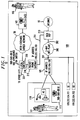
- Communications systems 10 comprises customer premises equipment 100, 2-way HFC plant 200 (referred to herein as HFC 200), data point-of-presence (POP) 210, Internet 55, packet phone gateway 215, local switch 220, inter-exchange carrier network 50, and far-end customer premises equipment 165. Also shown on FIG. 1 are other cable drops as represented by cable modems 81 and 82, which are also assumed to embody the inventive concept.
- HFC 200 2-way HFC plant 200
- POP data point-of-presence
- Internet 55 Internet 55
- packet phone gateway 215 packet phone gateway 215, local switch 220, inter-exchange carrier network 50, and far-end customer premises equipment 165.
- cable drops as represented by cable modems 81 and 82, which are also assumed to embody the inventive concept.
- Customer premises equipment 100 comprises data terminal equipment 110, telephone 115, and cable modem 105.
- Data terminal equipment 110 is illustratively a personal-computer equipped with a speaker and microphone for audio communications as known in the art along with the necessary hardware and software (not shown).
- Telephone 115 is illustratively a POTS telephone. Both Data terminal equipment 110 and telephone 115 are coupled to cable modem 105 (described below). The latter is coupled to HFC plant 200 via coaxial cable 201.
- Telephone 115 is identified by a telephone "directory number" (DN), e.g., 908-949-8818, and cable modem 105 has an associated "Internet Protocol" (IP) address, e.g., 199.222.104.150.
- DN telephone "directory number”
- IP Internet Protocol
- a user of customer premises equipment 100 is identified herein by user 101.
- the HFC plant 200 is representative of a 2-way, i.e., bi-directional transmission, cable network over a hybrid-fiber-coaxial cable distribution plant.
- This HFC distribution plant is terminated at the service provider s data POP 210, which is representative of equipment for switching packet data traffic.
- the data POP 210 is coupled to Internet 55 and packet phone gateway 215.
- Internet 55 illustratively represents the collection of facilities and networks that are called the Internet. (It should be noted that alternatively "intranets," or a combination of Internet/intranet networks, could be used).
- data POP 210 is coupled to packet phone gateway 215.
- the latter provides for the interface between a packet-switched environment and a circuit-switched environment in accordance with the principles of the invention (described below).
- the former environment being represented by HFC plant 200, data POP 210, and Internet 55; while the latter environment is represented by the PSTN as represented by local switch 220 and inter-exchange carrier network 50.
- Packet phone gateway 215 is coupled to the PSTN environment via an Integrated Services Digital Network (ISDN) interface 216, such as a basic rate interface (BRI), a primary rate interface (PRI), or others.
- ISDN Integrated Services Digital Network
- the PSTN environment is represented by local switch 220 and inter-exchange carrier network 50.
- local switch 220 is also coupled to other LECs (not shown), via facilities 221, and to inter-exchange carrier network 50.
- the latter provides communications with customer premises equipment 165, which is illustratively a POTS telephone coupled to inter-exchange carrier network 50 through an associated LEC (not shown).
- User 166 is associated with customer premises equipment 165, which is associated with a DN, or telephone number, of 303-714-0432.
- local switch 220 represents circuit-switching equipment. As such, physically, the functions of packet phone gateway 215 could be incorporated into the local switch.
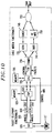
- FIG. 2 represents an illustrative method used herein to process a communications call between user 101 and user 166.
- the communications call is a voice call
- user 101 is the calling party and user 166 is the called party.
- user 101 dials a telephone number associated with the called party, user 166, as known in the art, e.g., lifting the handset, etc., of telephone 115.
- the called party telephone number, 303-714-0432 is also referred to as the "terminating DN.”
- cable modem 105 receives, from telephone 115, the sequence of touch-tone digits representing the terminating DN.
- cable modem 105 formats an ISDN Setup message comprising the terminating DN.
- ISDN equipment communicates signaling via an ISDN D-channel using the well known Q.931 standard.
- step 415 cable modem 105 formats an IP message for conveying ISDN D-channel signaling, with the originating, or source, IP address (199.222.104.150), and the destination IP address (e.g., 199.222.104.160).
- An illustrative IP message 250 is shown in FIG. 3.
- the above-mentioned ISDN Setup message is carried in the data portion of the IP message 250.
- this IP message is transmitted by cable modem 105 and sent over HFC 200 using TCP/IP.
- the data POP 210 receives the IP message in step 425.
- data POP 210 routes the IP packet to packet phone gateway 215, as a function of the destination IP address, which in this example represents packet phone gateway 215.
- Packet phone gateway 215 recovers the ISDN Setup message from the received IP packet in step 435.
- Packet phone gateway 215 retransmits the ISDN Setup message to local switch 220, via the D-channel of ISDN interface 216, in step 440.
- local switch 220 receives the ISDN Setup message and processes the call as in the prior art, e.g., eventually causing a ringing signal to appear at telephone set 165.
- packet phone gateway 215 communicates ISDN signaling information between local switch 220 and cable modem 105 in accordance with the principles of the invention.
- packet phone gateway 215 includes ISDN interface equipment to support ISDN interface 216 and IP packet equipment to support IP interface 211.
- call signaling information equivalent to states such as "setup,” “ringing,” “answer,” “disconnect.” etc. is communicated between local switch 220 and packet phone gateway 215 as ISDN signaling information via a D-channel of ISDN interface 216, and as part of a TCP/IP message between packet phone gateway 215 and cable modem 105.
- ISDN signaling message(s) are transmitted back to packet phone gateway 215 to complete a circuit-switched connection between packet phone gateway 215 and customer premises equipment 165 in step 450.
- packet phone gateway 215 conveys this telephony-type signaling information to cable modem 105, via data POP 210 and HFC 200, to complete the packet-switched connection between packet phone gateway 215 and cable modem 105.
- the packet phone gateway 215 maintains a data structure or routing table as shown in FIG. 5.
- This routing table associates three fields for each subscriber: subscriber IP address, subscriber telephone number, and associated packet phone gateway address.
- This illustrative routing table shows information for three different subscribers with cable modems 105, 81, and 82, respectively (shown in FIG. 1).
- packet phone gateway 215 is associated with a plurality of IP addresses, one for each subscriber. For example, the IP address of cable modem 105 and telephone number of user 101 are associated with an IP address for packet phone gateway 215 of 199.222.104.160.
- cable modem 105 of user 101 when cable modem 105 of user 101 sends a telephony-type signaling message using TCP/IP, it sends that message to IP address 199.222.104.160 of packet phone gateway 215.
- a telephony-type signaling message from cable modem 81 is conveyed via a TCP/IP message to IP address 199.222.104.161 of packet phone gateway 215.
- the source IP address of the TCP/IP message from a cable modem identifies the subscriber.
- packet phone gateway 215 additionally uses the destination IP address to receive messages from a specific subscriber. (It should be noted that a single IP address could be used instead for packet phone gateway 215, or, alternatively, different groups of subscribers could be assigned with different packet phone gateway IP addresses.)
- the routing table of FIG. 5 is used by packet phone gateway 215 to relay ISDN signaling from local switch 220 to the respective subscriber. For example, incoming ISDN signaling messages corresponding to DNs listed in the table of FIG. 5 are relayed by packet phone gateway 215 to the corresponding cable modem at the indicated IP address.
- packet phone gateway 215 receives an incoming ISDN signaling message identifying DN 908-949-8818, packet phone gateway 215 translates the DN to the corresponding IP address for cable modem 105, and retransmits the ISDN signaling message in a TCP/IP message to IP address 199.222.104.150 (cable modem 105).
- cable modem 105 provides any of a number audio signals to user 101 to reflect call progress responsive to received telephony-type signaling messages as represented by the ISDN-TCP/IP signaling. For example, when an incoming call is being placed to user 101, cable modem 105 first receives the respective ISDN signaling message and in response thereto provides ringing to alert the user. (It should be noted that in accordance with ISDN practice, some audible signaling, such as ringing is generated by the customer premises equipment (here, in accordance with the inventive concept, cable modem 105).
- cable modem 105 samples and digitizes voice for transmission to the called party as known in the art.
- the "User Datagram Protocol" (UDP) is used to transmit voice packets to packet phone gateway 215 over the packet-switched portion of the connection.
- UDP User Datagram Protocol
- This UDP/IP method of sending voice packets over a packet-switched connection is well-known and minimizes packet-switched delays.
- packet phone gateway 215 Upon receiving the packets containing audio information, packet phone gateway 215 depacketizes the audio and provides the audio digital bit stream to the prior assigned B-channel of ISDN interface 216 (determined during call setup). Similarly, in the reverse direction, packet phone gateway 215 packetizes the received audio digital bit stream for transmission to cable modem 105 via UDP/IP. Responding to the received UDP/IP messages, cable modem 105 depacketizes and converts received audio samples to an analog form for transmission to telephone 115.
- FIGs. 6 and 7 show the protocol relationships between the packet-side and the PSTN-side for the control signaling (FIG. 6) and the user channel (FIG. 7). It should be noted in FIG. 6 that ISDN call control can use H.323 setup standards.
- the telephone call uses packet transport between cable modem 105 and packet phone gateway 215, and circuit transport beyond.
- 64 kbps of bandwidth is available for a voice call over a single ISDN B-channel no audio compression is necessary.
- voice calls to a packet-switched endpoint e.g., off of Internet 55 of FIG. 1, may require compression.
- cable modem 105 is modified in any number of fashions to activate compression/decompression functions as known in the art.
- cable 105 can be administered by the user, e.g., via an equivalent "AT-type command" to use compression.
- cable modem 105 can adaptively use compression based, e.g., on the destination IP address.
- Cable modem 105 comprises telephony portion 600 and packet portion 700. Although not shown, it is assumed cable modem 105 is powered locally (versus receiving power through HFC 200). (It should be noted that various safeguards can be taken for ensuring power to cable modem 105, e.g., via a power source with battery backup, etc.) As can be observed from FIG. 8, cable modem 105 couples to PC 110, telephone 115, and HFC 200. Also shown in FIG. 8 is a coupling to an analog or digital TV set (described briefly below).
- Cable modem functionality portion 700 comprises memory 705, CPU 725, receiver 735, tuner 745, and splitter/combiner 755, and ethernet interface 760.
- Splitter/combiner 755 includes a "diplex filter" as known in the art. (It should be noted that, alternatively, splitter/combiner 755 can be external to cable modem 105.)
- CPU 725 is a stored-program-controlled central processing unit as known in the art, e.g., a microprocessor, coupled to memory 705, which provides both program storage and data storage.
- CPU 725 controls both the transmission, and reception, of packets to, and from, HFC 200 via splitter/combiner 755.
- CPU 725 formats data into IP packets for application to framer 730, which "frames-up" the received data to generate a sequence of TCP/IP or UDP/IP frames to transmitter 740.
- the latter provides additional error correction/detection coding such as Reed-Solomon coding as known in the art and forms a modulated intermediate frequency (IF) carrier signal to radio frequency (RF) modulator 750, which develops the modulated-RF signal for transmission over HFC 200 (e.g., QPSK modulation as known in the art for upstream traffic).
- IF intermediate frequency
- RF radio frequency
- a modulated RF signal is received from HFC 200, via splitter/combiner 755, for application to tuner 745.
- the latter recovers an RF-modulated signal at a predefined tuner frequency (e.g., QAM modulation as known in the art for downstream traffic).
- the recovered RF modulated signal is applied to receiver 735 which demodulates the recovered RF modulated signal and provides a sequence of received TCP/IP or UDP/IP frames to framer 730.
- the latter provides a stream of packets to CPU 725, which also controls framer 730 via signal 726 for the purpose of timing/synchronization and error detection.
- Cable modem 105 terminates a cable signal - which is divided into different frequency bands, e.g., a broadcast video channel and a data channel (for packets).
- Splitter/combiner 755 provides any cable-TV signaling to TV 170 (it is assumed for the purposes of this example, that TV 170 includes any required cable TV decoding function).
- CPU 725 forms packets from the digital audio information received from the telephony portion 600.
- CPU 725 also handles packets from ethernet interface 760, which transmits packets.
- Ethernet interface 760 couples to data terminal equipment, or personal computer (PC), 110.
- PC personal computer
- the latter forms a multi-media endpoint. That is, PC 110 (as mentioned earlier) is suitably configured to support the transmission and reception of data and audio as might be required, e.g., in an audio conferencing application.
- PC 110 provides data and audio information in the form of packets.
- Telephony portion 600 comprises memory 625, DSP 620, converter 610, and subscriber-line-interface-circuit (SLIC) 605.
- the heart of telephony portion 600 is DSP 620 and memory 625.
- DSP 620 is a stored-program-control digital signal processor as known in the art.
- Memory 625 provides both program storage and data storage for DSP 620.
- SLIC 605 provides the tip/ring interface to telephone 115.
- Converter 610 provides the interface between the digital world and the analog world, i.e., converter 610 is simply a pair of analog-to-digital and digital-to-analog converters.
- Telephony portion 600 provides a number of functions. First, a telephone network simulator function, via SLIC 605.
- cable modem 105 "looks like" the local loop of a telephone network to telephone 115, via port 604. As a result, no modifications are required to be made to telephone 115 to work with the inventive concept.
- This telephone network simulator function provides a set of well-known telephone signaling functions like the ability to sense off-hook, provide loop current, provide dial tone, detect dialing (pulse or DTMF), etc. Since these functions and their implementation are well-known, they are not described in detail.
- SLIC 605 is controlled by CPU 725 via line 606. Consequently, as ISDN signaling messages are received by CPU 725, the latter decodes the ISDN signaling messages and controls SLIC 605 to convey the proper signaling back to telephone 115. For example, "ringing,” etc. Similarly, in the other direction, SLIC 605 provides an "off-hook” indication, dialed digits, etc., to CPU 725, via control 606.
- CPU 725 formats this information into ISDN signaling messages as appropriate.
- PCM encoding and compression Another function performed by telephony portion 600 is the PCM encoding and compression (if necessary) of audio signals.
- SLIC 640 coveys audio signals to, and receives audio signals from, CPU 725, via converter 610. The latter converts between the analog domain and the digital domain (the latter represented as a PCM encoded signal or "DS0").
- DSP 620 provides for compression and decompression of PCM encoded signals.
- SLIC 640 conveys audio signals to, and receives audio signals from, DSP 620, via converter 610.
- DSP 620 receives PCM encoded audio from converter 610.
- DSP 620 provides compressed digital audio to CPU 725. Similarly, in the reverse direction, DSP 620 receives a compressed audio digital bit stream from CPU 725, decompresses this signal, and provides PCM encoded audio to converter 610, which then provides analog audio to telephone 115, via SLIC 605. As noted above, DSP 620 can be enabled or disabled in any number of ways to provide for the compression/decompression of the PCM encoded signaling.
- the inventive concept allows one to plug a regular telephone into cable modem 105 to make, and receive, voice calls over what is essentially a packet-switched network.
- This has additional human factors advantages. That is, most everyone knows how to use a plain old telephone set.
- Pick up the handset on telephone 115 and cable modem 105 provides dial-tone.
- Depress buttons on the dialing pad (not shown) of telephone 115 and cable modem 105 transmits an ISDN Setup message to packet phone gateway 215, where this ISDN Setup message includes the called party number.
- cable modem 105 converts between analog audio signals and digital audio signals, thus providing communication to the called party.
- CPU 725 causes SLIC 605 to apply a "ringing signal" to telephone 115.
- voice communications in the opposite direction are achieved.
- FIG. 8 shows one illustrative form of a cable modem in accordance with the principles of the invention
- a cable modem in accordance with the inventive concept can take on other forms as suggested by FIGs. 9 and 10.
- the packet telephony function and the cable modem interface function are distributed in different fashions.
- FIG. 9 is illustrative of a cable modem that only works with data terminal equipment configured to provide audio communications in accordance with the principles of the invention.
- incoming voice-only telephone calls from, e.g., user 166 cause cable modem 105 to provide an incoming call to PC 110, which either causes an alert (audible, such as a ringing signal, or visual) to be generated.
- an alert audible, such as a ringing signal, or visual
- FIG. 10 is illustrative of a cable modem that provides an integrated form of telephone.
- functionality previously found in telephone 115 is now included within the cable modem as represented by telephone 115'.
- cable modem 105 has a dial pad, handset, etc. (not shown).
- the cable modem is utilized primarily as a POTS telephone coupled to a packet-switched environment. It should be realized by those skilled in the art that integrating the functionality of telephone 115 into the cable modem provides the opportunity to simplify the circuit design.
Abstract
Description
Claims (8)
- A modem comprising:circuitry (604) for coupling to equipment that provides telephony functions; andcircuitry (730, 740, 750, 755) for transmitting the packets
CHARACTERIZED BYcircuitry (605, 610, 620, 625, 725) responsive to signaling from the equipment for forming packets for transmission such that some packets include telephony-type signaling information. - The apparatus of claim 1 further
CHARACTERIZED BYreceiving circuitry (735, 745) for receiving packets; andprocessing circuitry (605, 610, 620, 625, 725) responsive to telephony-type signaling information recovered from at least one received packet for ringing a telephone coupled to the modem. - The apparatus of claim 1 wherein the circuitry for forming packets includes telephony-type signaling information by including integrated-services-digital-network (ISDN) signaling messages in the respective packets.
- The apparatus of claim 3 wherein the ISDN signaling messages are compatible with Q.931.
- The apparatus of claim 1 wherein the circuitry for transmitting is for coupling to a cable network, whereby the modem is a cable modem.
- A method for use in equipment for providing telephone services over a cable network, the method
CHARACTERIZED BY THE STEPS OFcoupling to at least one packet facility and at least one switched facility;receiving a telephone signaling message from a switched facility coupled thereto, the telephone signaling message comprising, at least, a called party telephone number;identifying a packet address from the called party telephone number; andtransmitting the telephone signaling message in a packet form over the packet facility to the identified packet address. - The method of claim 6 wherein the transmitting step includes the step of using a transaction-control-protocol/Internet Protocol (TCP/IP) in transmitting the packet.
- The method of claim 7 wherein the telephone signaling message is an ISDN signaling message.
Applications Claiming Priority (2)
| Application Number | Priority Date | Filing Date | Title |
|---|---|---|---|
| US772711 | 1996-12-23 | ||
| US08/772,711 US6236653B1 (en) | 1996-12-23 | 1996-12-23 | Local telephone service over a cable network using packet voice |
Publications (3)
| Publication Number | Publication Date |
|---|---|
| EP0851653A2 true EP0851653A2 (en) | 1998-07-01 |
| EP0851653A3 EP0851653A3 (en) | 2004-01-14 |
| EP0851653B1 EP0851653B1 (en) | 2009-02-11 |
Family
ID=25095974
Family Applications (1)
| Application Number | Title | Priority Date | Filing Date |
|---|---|---|---|
| EP97309684A Expired - Lifetime EP0851653B1 (en) | 1996-12-23 | 1997-12-02 | Local telephone service over a cable network using packet voice |
Country Status (5)
| Country | Link |
|---|---|
| US (1) | US6236653B1 (en) |
| EP (1) | EP0851653B1 (en) |
| JP (1) | JP3573402B2 (en) |
| CA (1) | CA2221218A1 (en) |
| DE (1) | DE69739247D1 (en) |
Cited By (38)
| Publication number | Priority date | Publication date | Assignee | Title |
|---|---|---|---|---|
| WO1999043182A1 (en) * | 1998-02-17 | 1999-08-26 | Nova-Technik Entwicklung Von Und Handel Mit Medizinischen Geräten Gmbh | Method for transmitting digitised audio data and device for realising the same |
| EP0978984A2 (en) * | 1998-08-07 | 2000-02-09 | Lucent Technologies Inc. | Packet data transport mechanism |
| WO2000011904A2 (en) * | 1998-08-19 | 2000-03-02 | Nova-Technik Entwicklung Von Und Handel Mit Medizinischen Geräten Gmbh | Method and device for transmitting digitized information |
| WO2000030369A1 (en) * | 1998-11-10 | 2000-05-25 | Telefonaktiebolaget Lm Ericsson (Publ) | Security in telecommunications network gateways |
| WO2000033522A2 (en) * | 1998-11-30 | 2000-06-08 | Broadcom Corporation | Network telephony system |
| WO2000036852A2 (en) * | 1998-12-18 | 2000-06-22 | Ericsson, Inc. | Mechanism and method for distributing isup stacks over multiple loosely coupled processors |
| WO2000046964A1 (en) * | 1999-02-02 | 2000-08-10 | Telefonaktiebolaget Lm Ericsson (Publ) | Telecommunication system and method in a telecommunication system |
| WO2000074360A1 (en) * | 1999-05-31 | 2000-12-07 | Nortel Networks Limited | Connection device with real time and non-real time data ports |
| EP1091551A2 (en) | 1999-10-08 | 2001-04-11 | Siemens Aktiengesellschaft | Method for operating a switching device using different signalling protocols |
| EP1093278A2 (en) * | 1999-10-12 | 2001-04-18 | Nec Corporation | Access network based on the Internet Protocol |
| EP1117214A2 (en) * | 2000-01-14 | 2001-07-18 | Terayon Communication Systems, Inc. | Home network gateway |
| EP1129571A1 (en) * | 1998-11-13 | 2001-09-05 | Genesys Telecommunications Laboratories, Inc. | Private ip telephony backbone linking widely-distributed enterprise sites |
| WO2001078415A1 (en) * | 2000-04-06 | 2001-10-18 | Siemens Aktiengesellschaft | Arrangement for connecting a telecommunications device to a packet-switching communications network |
| WO2001078348A2 (en) * | 2000-04-07 | 2001-10-18 | Infineon Technologies North America Corp. | Integrated access device controller |
| EP1163589A1 (en) * | 1999-01-29 | 2001-12-19 | General Instrument Corporation | Authentication enforcement using decryption and authentication in a single transaction in a secure microprocessor |
| EP1170963A2 (en) * | 2000-07-03 | 2002-01-09 | Siemens Aktiengesellschaft | Data transmission between two communication exchanges over a packet-oriented communication network |
| WO2002013472A1 (en) * | 2000-08-10 | 2002-02-14 | Marconi Communications Limited | Data processing system |
| FR2813480A1 (en) * | 2000-08-29 | 2002-03-01 | Sagem | Analogue terminal digital internet input connection having channel inputs pointer directed and separator analogue/digital lines connecting passing input line. |
| WO2002019757A1 (en) * | 2000-08-29 | 2002-03-07 | General Dynamics Decision Systems, Inc. | Providing interoperation between communication systems |
| WO2002023824A2 (en) * | 2000-09-11 | 2002-03-21 | Broadcom Corporation | Cable modem with voice processing capability |
| CN1085456C (en) * | 1999-03-02 | 2002-05-22 | 中信通信项目管理有限责任公司 | Broadband multi-purpose digital intelligent telephone |
| EP1281129A1 (en) * | 2000-04-09 | 2003-02-05 | Lea-D Corporation Ltd. | Method and system for end-to-end communication over the internet transmission infrastructure |
| EP1333616A2 (en) * | 2001-12-28 | 2003-08-06 | Kabushiki Kaisha Toshiba | Cable modem and protocol conversion processing method |
| EP1143682A3 (en) * | 2000-04-06 | 2003-12-03 | The Distribution Systems Research Institute | Terminal-to-terminal communication connection control method using IP transfer network |
| US6885657B1 (en) | 1998-11-30 | 2005-04-26 | Broadcom Corporation | Network telephony system |
| US7028100B2 (en) | 2000-07-12 | 2006-04-11 | The Distribution Systems Research Institute | Integrated information communication system for detecting and discarding external data packets that violate addressing rules |
| US7042957B1 (en) | 1998-12-15 | 2006-05-09 | Siemens Aktiengesellschaft | Method and communication system for transmitting information with the aid of a multicarrier method |
| GB2420676A (en) * | 2004-11-09 | 2006-05-31 | Rockwell Electronic Commerce | TCP/IP transport interface for ISDN telephone |
| US7061904B2 (en) | 1999-09-13 | 2006-06-13 | Infineon Technologies North America Corp. | Integrated access device controller |
| US7301952B2 (en) | 2000-04-06 | 2007-11-27 | The Distribution Systems Research Institute | Terminal-to-terminal communication connection control method using IP transfer network |
| US7373429B2 (en) | 1999-05-10 | 2008-05-13 | The Distribution Systems Research Institute | Integrated IP network |
| EP1942607A2 (en) | 2000-09-11 | 2008-07-09 | Broadcom Corporation | Cable modem with voice processing capability |
| US7440456B2 (en) | 2001-06-08 | 2008-10-21 | The Distribution Systems Research Institute | Terminal-to-terminal communication connection control system for IP full service |
| US7933295B2 (en) | 1999-04-13 | 2011-04-26 | Broadcom Corporation | Cable modem with voice processing capability |
| US7983307B2 (en) * | 2002-03-27 | 2011-07-19 | Apple Inc. | Communication apparatus and communication method |
| US8072979B2 (en) | 2002-06-07 | 2011-12-06 | The Distribution Systems Research Institute | Terminal-to-terminal communication control system for IP full service |
| US8176553B1 (en) | 2001-06-29 | 2012-05-08 | Mcafee, Inc. | Secure gateway with firewall and intrusion detection capabilities |
| US8416769B2 (en) | 1998-11-20 | 2013-04-09 | Level 3 Communications, Llc | System and method for bypassing data from egress facilities |
Families Citing this family (80)
| Publication number | Priority date | Publication date | Assignee | Title |
|---|---|---|---|---|
| US6324267B1 (en) * | 1997-01-17 | 2001-11-27 | Scientific-Atlanta, Inc. | Two-tiered authorization and authentication for a cable data delivery system |
| US6804225B1 (en) * | 1997-03-03 | 2004-10-12 | Softalk Inc. | System and method for establishing long distance voice communications using the internet |
| US7184430B2 (en) * | 1997-06-30 | 2007-02-27 | Siemens Communications, Inc. | Telecommunication system |
| EP0931397A1 (en) * | 1997-08-13 | 1999-07-28 | Koninklijke Philips Electronics N.V. | Method and system for a two-step dialing connection process providing an identification of a second terminal via the internet |
| KR100252120B1 (en) * | 1997-12-29 | 2000-04-15 | 윤종용 | Internet telephone service apparatus and method in ip supported cable network |
| WO1999037059A1 (en) * | 1998-01-14 | 1999-07-22 | At & T Corp. | A method and system for telephony and high speed data access on a broadband access network |
| JPH11225218A (en) * | 1998-02-05 | 1999-08-17 | Matsushita Electric Ind Co Ltd | Internet telephone system, communication system utillizing wide area data communication network, and terminal adapter |
| WO1999053627A1 (en) | 1998-04-10 | 1999-10-21 | Chrimar Systems, Inc. Doing Business As Cms Technologies | System for communicating with electronic equipment on a network |
| US6349133B1 (en) * | 1998-04-15 | 2002-02-19 | Premisenet Incorporated | Method and system for interfacing a telephony network and a digital data stream |
| GB2337893B (en) * | 1998-05-28 | 2000-09-06 | Matsushita Electric Ind Co Ltd | Internet telephone apparatus and internet telephone gateway system |
| FR2780592B1 (en) * | 1998-06-25 | 2000-08-04 | Alsthom Cge Alcatel | METHOD FOR TRANSMITTING SIGNALING DATA |
| US6470008B1 (en) * | 1998-07-09 | 2002-10-22 | Sprint Communications Company L.P. | Internet routing system |
| US6693893B1 (en) * | 1998-07-28 | 2004-02-17 | At&T Corp. | Method and apparatus for accessing a telephone network from the internet |
| US6480510B1 (en) | 1998-07-28 | 2002-11-12 | Serconet Ltd. | Local area network of serial intelligent cells |
| US6560216B1 (en) * | 1998-09-17 | 2003-05-06 | Openwave Systems Inc. | Data network computing device call processing |
| US6714533B1 (en) * | 1998-11-30 | 2004-03-30 | Qwest Communications International Inc. | Method and system for managing a packet switched network |
| KR100608638B1 (en) * | 1998-12-05 | 2006-10-24 | 엘지전자 주식회사 | Control Method of Internet Phone System |
| US6504839B2 (en) * | 1998-12-21 | 2003-01-07 | Ericsson Inc. | Apparatus, methods and systems for routing information from a packet-switched network to a mobile device communicating with a wireless telecommunications network |
| US6810036B1 (en) * | 1998-12-31 | 2004-10-26 | Nortel Networks Limited | Caller IP address |
| US6785267B1 (en) * | 1999-01-04 | 2004-08-31 | Cisco Technology, Inc. | Access and control system for enhanced audio capabilities in an integrated telephony/high speed data access device |
| US6618386B1 (en) * | 1999-03-04 | 2003-09-09 | Webtv Networks, Inc. | Hosting a cable modem in a computer using a virtual bridge |
| US6618387B1 (en) * | 1999-03-04 | 2003-09-09 | Webtv Networks, Inc. | Interface for abstracting control of a cable modem |
| US6889258B1 (en) * | 1999-03-04 | 2005-05-03 | Webtv Networks, Inc. | Automatic compiling of address filter information |
| US6765931B1 (en) * | 1999-04-13 | 2004-07-20 | Broadcom Corporation | Gateway with voice |
| US6956826B1 (en) | 1999-07-07 | 2005-10-18 | Serconet Ltd. | Local area network for distributing data communication, sensing and control signals |
| US6512764B1 (en) | 1999-07-16 | 2003-01-28 | General Bandwidth Inc. | Method and apparatus for providing voice signals to and from a telecommunications switch |
| US6690677B1 (en) * | 1999-07-20 | 2004-02-10 | Serconet Ltd. | Network for telephony and data communication |
| KR100312598B1 (en) * | 1999-07-27 | 2001-11-03 | 서평원 | System of Performing Voice over Internet Protocol in the Switching System |
| US6958999B1 (en) * | 1999-08-11 | 2005-10-25 | World Telecom Labs N.V. | Frame bundling and payload switching |
| ATE388542T1 (en) * | 1999-12-13 | 2008-03-15 | Broadcom Corp | VOICE THROUGH DEVICE WITH DOWNWARD VOICE SYNCHRONIZATION |
| US6937713B1 (en) | 1999-12-30 | 2005-08-30 | At&T Corp. | IP call forward profile |
| US7180889B1 (en) * | 1999-12-30 | 2007-02-20 | At&T Corp. | Personal control of address assignment and greeting options for multiple BRG ports |
| US6826173B1 (en) * | 1999-12-30 | 2004-11-30 | At&T Corp. | Enhanced subscriber IP alerting |
| US6889321B1 (en) | 1999-12-30 | 2005-05-03 | At&T Corp. | Protected IP telephony calls using encryption |
| US6680935B1 (en) | 1999-12-30 | 2004-01-20 | At&T Corp. | Anonymous call rejection |
| US6775267B1 (en) | 1999-12-30 | 2004-08-10 | At&T Corp | Method for billing IP broadband subscribers |
| US20040015607A1 (en) * | 2000-01-28 | 2004-01-22 | Bender Paul E. | System and method for using an IP address as a wireless unit identifier |
| US6671735B1 (en) * | 2000-01-28 | 2003-12-30 | Qualcomm Incorporated | System and method for using an IP address as a wireless unit identifier |
| US6549616B1 (en) | 2000-03-20 | 2003-04-15 | Serconet Ltd. | Telephone outlet for implementing a local area network over telephone lines and a local area network using such outlets |
| IL135744A (en) | 2000-04-18 | 2008-08-07 | Mosaid Technologies Inc | Telephone communication system over a single telephone line |
| US6842459B1 (en) | 2000-04-19 | 2005-01-11 | Serconet Ltd. | Network combining wired and non-wired segments |
| US7324635B2 (en) | 2000-05-04 | 2008-01-29 | Telemaze Llc | Branch calling and caller ID based call routing telephone features |
| US7535887B1 (en) * | 2000-06-20 | 2009-05-19 | Alcatel-Lucent Usa Inc. | Packetizing telecommunications switch |
| US6847635B1 (en) * | 2000-06-20 | 2005-01-25 | 3Com Corporation | Method to transmit silence compressed voice over IP efficiently in DOCSIS cable networks |
| US7675900B1 (en) | 2000-10-09 | 2010-03-09 | Genband Inc. | System and method for interfacing between signaling protocols |
| US8127326B2 (en) * | 2000-11-14 | 2012-02-28 | Claussen Paul J | Proximity detection using wireless connectivity in a communications system |
| WO2002047388A2 (en) | 2000-11-14 | 2002-06-13 | Scientific-Atlanta, Inc. | Networked subscriber television distribution |
| US7184427B1 (en) * | 2000-11-28 | 2007-02-27 | Genband Inc. | System and method for communicating telecommunication information from a broadband network to a telecommunication network |
| WO2002049298A1 (en) | 2000-12-14 | 2002-06-20 | Powerhouse Technology, Inc. | Circuit switched cellulat network to internet calling |
| US7002951B2 (en) * | 2001-02-14 | 2006-02-21 | 3Com Corporation | Automatic voicemail announcements with multimedia attachments |
| IL144158A (en) | 2001-07-05 | 2011-06-30 | Mosaid Technologies Inc | Outlet for connecting an analog telephone set to a digital data network carrying voice signals in digital form |
| US7080400B1 (en) | 2001-08-06 | 2006-07-18 | Navar Murgesh S | System and method for distributed storage and presentation of multimedia in a cable network environment |
| IL161190A0 (en) | 2001-10-11 | 2004-08-31 | Serconet Ltd | Outlet with analog signal adapter, method for use thereof and a network using said outlet |
| US6707893B1 (en) | 2002-07-10 | 2004-03-16 | At&T Corp. | Call progress information in cable telephony |
| US7516470B2 (en) | 2002-08-02 | 2009-04-07 | Cisco Technology, Inc. | Locally-updated interactive program guide |
| US20040057576A1 (en) * | 2002-09-23 | 2004-03-25 | Simon Lavaud | System and method for on-demand battery backup for cable telephony device |
| US20040064363A1 (en) * | 2002-09-30 | 2004-04-01 | Mostad Matthew A. | Technique for effectively promoting goods for service through an information assistance service |
| US7908625B2 (en) * | 2002-10-02 | 2011-03-15 | Robertson Neil C | Networked multimedia system |
| US20040068753A1 (en) * | 2002-10-02 | 2004-04-08 | Robertson Neil C. | Video transmission systems and methods for a home network |
| US7360235B2 (en) | 2002-10-04 | 2008-04-15 | Scientific-Atlanta, Inc. | Systems and methods for operating a peripheral record/playback device in a networked multimedia system |
| US8046806B2 (en) | 2002-10-04 | 2011-10-25 | Wall William E | Multiroom point of deployment module |
| IL152824A (en) * | 2002-11-13 | 2012-05-31 | Mosaid Technologies Inc | Addressable outlet and a network using same |
| US7653192B1 (en) * | 2002-12-20 | 2010-01-26 | Nortel Networks Limited | Multimedia augmented conference bridge |
| US8094640B2 (en) | 2003-01-15 | 2012-01-10 | Robertson Neil C | Full duplex wideband communications system for a local coaxial network |
| US7336604B2 (en) * | 2003-02-13 | 2008-02-26 | Innomedia Pte | Network access module for supporting a stand alone multi-media terminal adapter |
| US20040160945A1 (en) * | 2003-02-13 | 2004-08-19 | Innomedia Pte Ltd. | Network communication system with a stand alone multi-media terminal adapter |
| IL154921A (en) | 2003-03-13 | 2011-02-28 | Mosaid Technologies Inc | Telephone system having multiple distinct sources and accessories therefor |
| CA2530892C (en) * | 2003-06-27 | 2015-10-27 | Qualcomm Incorporated | Method and apparatus for wireless network hybrid positioning |
| IL157787A (en) | 2003-09-07 | 2010-12-30 | Mosaid Technologies Inc | Modular outlet for data communications network |
| IL159838A0 (en) | 2004-01-13 | 2004-06-20 | Yehuda Binder | Information device |
| IL160417A (en) | 2004-02-16 | 2011-04-28 | Mosaid Technologies Inc | Outlet add-on module |
| US7397793B2 (en) * | 2004-04-05 | 2008-07-08 | Cisco Technology, Inc. | V.110 over packet networks |
| US7451921B2 (en) * | 2004-09-01 | 2008-11-18 | Eric Morgan Dowling | Methods, smart cards, and systems for providing portable computer, VoIP, and application services |
| US7873058B2 (en) | 2004-11-08 | 2011-01-18 | Mosaid Technologies Incorporated | Outlet with analog signal adapter, a method for use thereof and a network using said outlet |
| JP4327747B2 (en) * | 2005-02-21 | 2009-09-09 | 双葉電子工業株式会社 | Electronic device having non-evaporable getter and method for manufacturing the electronic device |
| US7876998B2 (en) | 2005-10-05 | 2011-01-25 | Wall William E | DVD playback over multi-room by copying to HDD |
| US20070169162A1 (en) * | 2006-01-18 | 2007-07-19 | Srinivas Kola | Hierarchical communications network with upstream signal controllable from head end |
| TWI396396B (en) * | 2009-11-10 | 2013-05-11 | Hon Hai Prec Ind Co Ltd | Noise detecting device |
| US8599780B2 (en) * | 2010-04-28 | 2013-12-03 | Quantenna Communications, Inc. | Access point range extension |
| US9247044B2 (en) * | 2013-03-15 | 2016-01-26 | Time Warner Cable Enterprises Llc | Remote control and call management resource |
Citations (3)
| Publication number | Priority date | Publication date | Assignee | Title |
|---|---|---|---|---|
| WO1995027350A1 (en) * | 1994-03-30 | 1995-10-12 | Scientific-Atlanta, Inc. | Frequency agile broadband communications system |
| WO1996027241A1 (en) * | 1995-02-28 | 1996-09-06 | Motorola Inc. | Data communications device to selectively operate as an analog modem, a digital modem, and a terminal adapter |
| WO1996027967A1 (en) * | 1995-03-03 | 1996-09-12 | Intecom, Incorporated | Multimedia bridge |
Family Cites Families (5)
| Publication number | Priority date | Publication date | Assignee | Title |
|---|---|---|---|---|
| US5341374A (en) * | 1991-03-01 | 1994-08-23 | Trilan Systems Corporation | Communication network integrating voice data and video with distributed call processing |
| WO1994030028A1 (en) * | 1993-06-16 | 1994-12-22 | Com 21, Inc. | Multi protocol personal communications system |
| US5581555A (en) * | 1993-09-17 | 1996-12-03 | Scientific-Atlanta, Inc. | Reverse path allocation and contention resolution scheme for a broadband communications system |
| JPH07170288A (en) * | 1993-12-15 | 1995-07-04 | Hitachi Ltd | Voice communication system and voice communication method |
| US6028860A (en) * | 1996-10-23 | 2000-02-22 | Com21, Inc. | Prioritized virtual connection transmissions in a packet to ATM cell cable network |
-
1996
- 1996-12-23 US US08/772,711 patent/US6236653B1/en not_active Expired - Lifetime
-
1997
- 1997-11-17 CA CA002221218A patent/CA2221218A1/en not_active Abandoned
- 1997-12-02 EP EP97309684A patent/EP0851653B1/en not_active Expired - Lifetime
- 1997-12-02 DE DE69739247T patent/DE69739247D1/en not_active Expired - Lifetime
- 1997-12-19 JP JP35159697A patent/JP3573402B2/en not_active Expired - Fee Related
Patent Citations (3)
| Publication number | Priority date | Publication date | Assignee | Title |
|---|---|---|---|---|
| WO1995027350A1 (en) * | 1994-03-30 | 1995-10-12 | Scientific-Atlanta, Inc. | Frequency agile broadband communications system |
| WO1996027241A1 (en) * | 1995-02-28 | 1996-09-06 | Motorola Inc. | Data communications device to selectively operate as an analog modem, a digital modem, and a terminal adapter |
| WO1996027967A1 (en) * | 1995-03-03 | 1996-09-12 | Intecom, Incorporated | Multimedia bridge |
Cited By (75)
| Publication number | Priority date | Publication date | Assignee | Title |
|---|---|---|---|---|
| WO1999043182A1 (en) * | 1998-02-17 | 1999-08-26 | Nova-Technik Entwicklung Von Und Handel Mit Medizinischen Geräten Gmbh | Method for transmitting digitised audio data and device for realising the same |
| EP0978984A2 (en) * | 1998-08-07 | 2000-02-09 | Lucent Technologies Inc. | Packet data transport mechanism |
| EP0978984A3 (en) * | 1998-08-07 | 2002-02-06 | Lucent Technologies Inc. | Packet data transport mechanism |
| WO2000011904A2 (en) * | 1998-08-19 | 2000-03-02 | Nova-Technik Entwicklung Von Und Handel Mit Medizinischen Geräten Gmbh | Method and device for transmitting digitized information |
| WO2000011904A3 (en) * | 1998-08-19 | 2000-05-18 | Nova Technik Entwicklung Von U | Method and device for transmitting digitized information |
| WO2000030369A1 (en) * | 1998-11-10 | 2000-05-25 | Telefonaktiebolaget Lm Ericsson (Publ) | Security in telecommunications network gateways |
| EP1129571A4 (en) * | 1998-11-13 | 2004-12-01 | Genesys Telecomm Lab Inc | Private ip telephony backbone linking widely-distributed enterprise sites |
| EP1129571A1 (en) * | 1998-11-13 | 2001-09-05 | Genesys Telecommunications Laboratories, Inc. | Private ip telephony backbone linking widely-distributed enterprise sites |
| US8953585B2 (en) | 1998-11-20 | 2015-02-10 | Level 3 Communications, Llc | System and method for bypassing data from egress facilities |
| US8416769B2 (en) | 1998-11-20 | 2013-04-09 | Level 3 Communications, Llc | System and method for bypassing data from egress facilities |
| WO2000033522A2 (en) * | 1998-11-30 | 2000-06-08 | Broadcom Corporation | Network telephony system |
| WO2000033522A3 (en) * | 1998-11-30 | 2000-10-19 | Broadcom Corp | Network telephony system |
| US7936744B2 (en) | 1998-11-30 | 2011-05-03 | Broadcom Corporation | Network telephony system |
| US6885657B1 (en) | 1998-11-30 | 2005-04-26 | Broadcom Corporation | Network telephony system |
| US8619758B2 (en) | 1998-11-30 | 2013-12-31 | Broadcom Corporation | Network telephony system |
| US9019957B2 (en) | 1998-11-30 | 2015-04-28 | Broadcom Corporation | Network telephony system |
| US7042957B1 (en) | 1998-12-15 | 2006-05-09 | Siemens Aktiengesellschaft | Method and communication system for transmitting information with the aid of a multicarrier method |
| US6507649B1 (en) | 1998-12-18 | 2003-01-14 | Ericsson Inc. | Mechanism and method for distributing ISUP stacks over multiple loosely coupled processors |
| WO2000036852A3 (en) * | 1998-12-18 | 2000-10-19 | Ericsson Inc | Mechanism and method for distributing isup stacks over multiple loosely coupled processors |
| WO2000036852A2 (en) * | 1998-12-18 | 2000-06-22 | Ericsson, Inc. | Mechanism and method for distributing isup stacks over multiple loosely coupled processors |
| EP1163589A1 (en) * | 1999-01-29 | 2001-12-19 | General Instrument Corporation | Authentication enforcement using decryption and authentication in a single transaction in a secure microprocessor |
| EP1163589A4 (en) * | 1999-01-29 | 2009-05-13 | Gen Instrument Corp | Authentication enforcement using decryption and authentication in a single transaction in a secure microprocessor |
| WO2000046964A1 (en) * | 1999-02-02 | 2000-08-10 | Telefonaktiebolaget Lm Ericsson (Publ) | Telecommunication system and method in a telecommunication system |
| CN1085456C (en) * | 1999-03-02 | 2002-05-22 | 中信通信项目管理有限责任公司 | Broadband multi-purpose digital intelligent telephone |
| US7933295B2 (en) | 1999-04-13 | 2011-04-26 | Broadcom Corporation | Cable modem with voice processing capability |
| USRE46142E1 (en) | 1999-04-13 | 2016-09-06 | Broadcom Corporation | Modem with voice processing capability |
| US8582577B2 (en) | 1999-04-13 | 2013-11-12 | Broadcom Corporation | Modem with voice processing capability |
| US9288334B2 (en) | 1999-04-13 | 2016-03-15 | Broadcom Corporation | Modem with voice processing capability |
| US7373429B2 (en) | 1999-05-10 | 2008-05-13 | The Distribution Systems Research Institute | Integrated IP network |
| WO2000074360A1 (en) * | 1999-05-31 | 2000-12-07 | Nortel Networks Limited | Connection device with real time and non-real time data ports |
| US7061904B2 (en) | 1999-09-13 | 2006-06-13 | Infineon Technologies North America Corp. | Integrated access device controller |
| EP1091551A3 (en) * | 1999-10-08 | 2005-05-04 | Siemens Aktiengesellschaft | Method for operating a switching device using different signalling protocols |
| EP1091551A2 (en) | 1999-10-08 | 2001-04-11 | Siemens Aktiengesellschaft | Method for operating a switching device using different signalling protocols |
| EP1093278A3 (en) * | 1999-10-12 | 2002-11-27 | Nec Corporation | Access network based on the Internet Protocol |
| EP1093278A2 (en) * | 1999-10-12 | 2001-04-18 | Nec Corporation | Access network based on the Internet Protocol |
| EP1117214A3 (en) * | 2000-01-14 | 2001-09-12 | Terayon Communication Systems, Inc. | Home network gateway |
| EP1117214A2 (en) * | 2000-01-14 | 2001-07-18 | Terayon Communication Systems, Inc. | Home network gateway |
| US7733882B2 (en) | 2000-04-06 | 2010-06-08 | The Distribution Systems Research Institute | Terminal-to-terminal communication connection control method using IP transfer network |
| US8553677B2 (en) | 2000-04-06 | 2013-10-08 | The Distribution Systems Research Institute | Terminal to-terminal communication connection control method using IP transfer network |
| WO2001078415A1 (en) * | 2000-04-06 | 2001-10-18 | Siemens Aktiengesellschaft | Arrangement for connecting a telecommunications device to a packet-switching communications network |
| US8948161B2 (en) | 2000-04-06 | 2015-02-03 | The Distribution Systems Research Institute | Terminal-to-terminal communication connection control method using IP transfer network |
| US8934484B2 (en) | 2000-04-06 | 2015-01-13 | The Distribution Systems Research Institute | Terminal-to-terminal communication connection control method using IP transfer network |
| EP1143682A3 (en) * | 2000-04-06 | 2003-12-03 | The Distribution Systems Research Institute | Terminal-to-terminal communication connection control method using IP transfer network |
| US7301952B2 (en) | 2000-04-06 | 2007-11-27 | The Distribution Systems Research Institute | Terminal-to-terminal communication connection control method using IP transfer network |
| US8565245B2 (en) | 2000-04-06 | 2013-10-22 | The Distribution Systems Research Institute | Terminal-to-terminal communication connection control method using IP transfer network |
| US8121113B2 (en) | 2000-04-06 | 2012-02-21 | The Distribution Systems Research Institute | Terminal-to-terminal communication connection control method using IP transfer network |
| US7948995B2 (en) | 2000-04-06 | 2011-05-24 | The Distribution Systems Research Institute | Terminal-to-terminal communication connection control method using IP transfer network |
| US7782883B2 (en) | 2000-04-06 | 2010-08-24 | The Distribution Systems Research Institute | Terminal-to-terminal communication connection control method using IP transfer network |
| US7505471B2 (en) | 2000-04-06 | 2009-03-17 | The Distribution Systems Research Institute | Terminal-to-terminal communication connection control method using IP transfer network |
| WO2001078348A2 (en) * | 2000-04-07 | 2001-10-18 | Infineon Technologies North America Corp. | Integrated access device controller |
| CN100364298C (en) * | 2000-04-07 | 2008-01-23 | 因芬尼昂技术北美公司 | Integrated access device controller |
| WO2001078348A3 (en) * | 2000-04-07 | 2002-05-30 | Infineon Technologies Corp | Integrated access device controller |
| EP1281129A4 (en) * | 2000-04-09 | 2003-07-02 | Lea D Corp Ltd | Method and system for end-to-end communication over the internet transmission infrastructure |
| EP1281129A1 (en) * | 2000-04-09 | 2003-02-05 | Lea-D Corporation Ltd. | Method and system for end-to-end communication over the internet transmission infrastructure |
| EP1170963A3 (en) * | 2000-07-03 | 2005-09-21 | Siemens Aktiengesellschaft | Data transmission between two communication exchanges over a packet-oriented communication network |
| EP1170963A2 (en) * | 2000-07-03 | 2002-01-09 | Siemens Aktiengesellschaft | Data transmission between two communication exchanges over a packet-oriented communication network |
| US7028100B2 (en) | 2000-07-12 | 2006-04-11 | The Distribution Systems Research Institute | Integrated information communication system for detecting and discarding external data packets that violate addressing rules |
| US7516242B2 (en) | 2000-07-12 | 2009-04-07 | The Distribution Systems Research Institute | Integrated information communication system using conversion table to convert an external packet into an internal packet by embedding a header |
| WO2002013472A1 (en) * | 2000-08-10 | 2002-02-14 | Marconi Communications Limited | Data processing system |
| WO2002019757A1 (en) * | 2000-08-29 | 2002-03-07 | General Dynamics Decision Systems, Inc. | Providing interoperation between communication systems |
| USRE40057E1 (en) * | 2000-08-29 | 2008-02-12 | Lewis Sales Llc | Method and apparatus for providing interoperation between a digital communication system and a public switched telephone network |
| FR2813480A1 (en) * | 2000-08-29 | 2002-03-01 | Sagem | Analogue terminal digital internet input connection having channel inputs pointer directed and separator analogue/digital lines connecting passing input line. |
| EP1942607A3 (en) * | 2000-09-11 | 2008-07-30 | Broadcom Corporation | Cable modem with voice processing capability |
| WO2002023824A2 (en) * | 2000-09-11 | 2002-03-21 | Broadcom Corporation | Cable modem with voice processing capability |
| WO2002023824A3 (en) * | 2000-09-11 | 2003-09-04 | Broadcom Corp | Cable modem with voice processing capability |
| EP1942607A2 (en) | 2000-09-11 | 2008-07-09 | Broadcom Corporation | Cable modem with voice processing capability |
| US7440456B2 (en) | 2001-06-08 | 2008-10-21 | The Distribution Systems Research Institute | Terminal-to-terminal communication connection control system for IP full service |
| US8176553B1 (en) | 2001-06-29 | 2012-05-08 | Mcafee, Inc. | Secure gateway with firewall and intrusion detection capabilities |
| EP1333616A3 (en) * | 2001-12-28 | 2003-12-10 | Kabushiki Kaisha Toshiba | Cable modem and protocol conversion processing method |
| EP1333616A2 (en) * | 2001-12-28 | 2003-08-06 | Kabushiki Kaisha Toshiba | Cable modem and protocol conversion processing method |
| US7983307B2 (en) * | 2002-03-27 | 2011-07-19 | Apple Inc. | Communication apparatus and communication method |
| US8072979B2 (en) | 2002-06-07 | 2011-12-06 | The Distribution Systems Research Institute | Terminal-to-terminal communication control system for IP full service |
| GB2420676A (en) * | 2004-11-09 | 2006-05-31 | Rockwell Electronic Commerce | TCP/IP transport interface for ISDN telephone |
| US7590107B2 (en) | 2004-11-09 | 2009-09-15 | Marshall Peltz | TCP/IP transport interface for ISDN telephone |
| GB2420676B (en) * | 2004-11-09 | 2008-11-05 | Rockwell Electronic Commerce | Tcp/ip transport interface for isdn telephone |
Also Published As
| Publication number | Publication date |
|---|---|
| US6236653B1 (en) | 2001-05-22 |
| JP3573402B2 (en) | 2004-10-06 |
| CA2221218A1 (en) | 1998-06-23 |
| EP0851653A3 (en) | 2004-01-14 |
| JPH10210182A (en) | 1998-08-07 |
| DE69739247D1 (en) | 2009-03-26 |
| EP0851653B1 (en) | 2009-02-11 |
Similar Documents
| Publication | Publication Date | Title |
|---|---|---|
| US6236653B1 (en) | Local telephone service over a cable network using packet voice | |
| EP0898838B1 (en) | A modem with ip support | |
| US6370149B1 (en) | Telecommunication system, method and subscriber unit for use therein | |
| US8630302B2 (en) | System and network for deriving voice channels on a broadband communication line | |
| US7170987B2 (en) | Customer premises equipment that can support multiple call control languages or multiple call agents | |
| US5412660A (en) | ISDN-to-ISDN communication via satellite microwave radio frequency communications link | |
| US5602846A (en) | Simultaneous voice and data call establishment using a simultaneous voice and data modem pool and private branch exchange facilities | |
| EP1050155A1 (en) | System and method for providing ip/internet telephony | |
| EP0987870B1 (en) | Apparatus and method for accessing wireless trunks from a communications network | |
| WO2003019919A9 (en) | Architecture for linking multiple internet protocol telephony devices having a common telephone number | |
| KR20010105042A (en) | Multiple telecommunication coupling device | |
| US20030048772A1 (en) | System for converting GR303 signals to NCS signals | |
| US5920402A (en) | Use of compression to improve the sending of faxes over analog cellular | |
| US7187686B1 (en) | Telecommunication system, method and subscriber unit for use therein | |
| CA2509353C (en) | Telecommunications system, method and subscriber unit for use therein | |
| KR20020068438A (en) | Method for external call forwarding beween internet call and telephone network call in webphone system | |
| Becker | All about ISDN | |
| MXPA00007272A (en) | System and method for providing ip/internet telephony | |
| MXPA01010775A (en) | Wide area communication networking |
Legal Events
| Date | Code | Title | Description |
|---|---|---|---|
| PUAI | Public reference made under article 153(3) epc to a published international application that has entered the european phase |
Free format text: ORIGINAL CODE: 0009012 |
|
| AK | Designated contracting states |
Kind code of ref document: A2 Designated state(s): AT BE CH DE DK ES FI FR GB GR IE IT LI LU MC NL PT SE |
|
| AX | Request for extension of the european patent |
Free format text: AL;LT;LV;MK;RO;SI |
|
| PUAL | Search report despatched |
Free format text: ORIGINAL CODE: 0009013 |
|
| AK | Designated contracting states |
Kind code of ref document: A3 Designated state(s): AT BE CH DE DK ES FI FR GB GR IE IT LI LU MC NL PT SE |
|
| AX | Request for extension of the european patent |
Extension state: AL LT LV MK RO SI |
|
| RIC1 | Information provided on ipc code assigned before grant |
Ipc: 7H 04L 12/28 A |
|
| 17P | Request for examination filed |
Effective date: 20040703 |
|
| AKX | Designation fees paid |
Designated state(s): DE FR GB |
|
| 17Q | First examination report despatched |
Effective date: 20040903 |
|
| 17Q | First examination report despatched |
Effective date: 20040903 |
|
| GRAP | Despatch of communication of intention to grant a patent |
Free format text: ORIGINAL CODE: EPIDOSNIGR1 |
|
| GRAS | Grant fee paid |
Free format text: ORIGINAL CODE: EPIDOSNIGR3 |
|
| GRAA | (expected) grant |
Free format text: ORIGINAL CODE: 0009210 |
|
| AK | Designated contracting states |
Kind code of ref document: B1 Designated state(s): DE FR GB |
|
| REG | Reference to a national code |
Ref country code: GB Ref legal event code: FG4D |
|
| REF | Corresponds to: |
Ref document number: 69739247 Country of ref document: DE Date of ref document: 20090326 Kind code of ref document: P |
|
| RAP4 | Party data changed (patent owner data changed or rights of a patent transferred) |
Owner name: LUCENT TECHNOLOGIES INC. |
|
| PLBE | No opposition filed within time limit |
Free format text: ORIGINAL CODE: 0009261 |
|
| STAA | Information on the status of an ep patent application or granted ep patent |
Free format text: STATUS: NO OPPOSITION FILED WITHIN TIME LIMIT |
|
| 26N | No opposition filed |
Effective date: 20091112 |
|
| REG | Reference to a national code |
Ref country code: GB Ref legal event code: 732E Free format text: REGISTERED BETWEEN 20131121 AND 20131127 |
|
| REG | Reference to a national code |
Ref country code: FR Ref legal event code: CD Owner name: ALCATEL-LUCENT USA INC. Effective date: 20131122 |
|
| REG | Reference to a national code |
Ref country code: FR Ref legal event code: GC Effective date: 20140410 |
|
| REG | Reference to a national code |
Ref country code: FR Ref legal event code: RG Effective date: 20141015 |
|
| REG | Reference to a national code |
Ref country code: FR Ref legal event code: PLFP Year of fee payment: 19 |
|
| PGFP | Annual fee paid to national office [announced via postgrant information from national office to epo] |
Ref country code: DE Payment date: 20151211 Year of fee payment: 19 Ref country code: GB Payment date: 20151221 Year of fee payment: 19 |
|
| PGFP | Annual fee paid to national office [announced via postgrant information from national office to epo] |
Ref country code: FR Payment date: 20151221 Year of fee payment: 19 |
|
| REG | Reference to a national code |
Ref country code: DE Ref legal event code: R119 Ref document number: 69739247 Country of ref document: DE |
|
| GBPC | Gb: european patent ceased through non-payment of renewal fee |
Effective date: 20161202 |
|
| REG | Reference to a national code |
Ref country code: FR Ref legal event code: ST Effective date: 20170831 |
|
| PG25 | Lapsed in a contracting state [announced via postgrant information from national office to epo] |
Ref country code: FR Free format text: LAPSE BECAUSE OF NON-PAYMENT OF DUE FEES Effective date: 20170102 |
|
| PG25 | Lapsed in a contracting state [announced via postgrant information from national office to epo] |
Ref country code: GB Free format text: LAPSE BECAUSE OF NON-PAYMENT OF DUE FEES Effective date: 20161202 Ref country code: DE Free format text: LAPSE BECAUSE OF NON-PAYMENT OF DUE FEES Effective date: 20170701 |