Field of the Invention
The present invention relates to lasers and more specifically to laser
components and to methods for designing and making laser components which
compensate for heat distortion and other distortions or aberrations in the laser
system.
Background of the Invention
Conventional laser cavity design techniques contemplate a resonator
cavity, shown in Figure 1, comprising two reflecting elements 110 and 112,
surrounding a gain medium 111. The gain medium can be a plasma, a gas, a
liquid, or a solid (e.g., a crystal or a semiconductor). The gain medium is
excited by a power source.
The term "laser" as used in this discussion is meant to be inclusive of
stimulated emission oscillators of electromagnetic radiation of any frequency
from radio-frequency (RF) to beyond x-ray frequencies. (RF lasers are
sometimes called "masers" by others.) The laser beam will have one or more
"modes". A mode in this discussion refers to a "spatial mode", also called a
"spatial eigenmode". The mode, a characteristic of the laser beam, is created
within a laser cavity and has both a power-distribution profile and a phase-distribution
profile. These mode profiles are generally expressed in
dimensions transverse to the direction of propagation of the laser beam. A
spatial mode is to be distinguished from a "temporal mode", which describes
the frequency characteristics of the laser beam. A "fundamental mode" is the
spatial mode which has the least loss. Amplitude profile 114 of Figure 1
illustrates a Gaussian fundamental mode versus transverse beam radius ρ.
Amplitude profile 115 of Figure 1 also illustrates a Gaussian fundamental
mode along with a second-order mode shown by curves 116 and 117.
The term "complex" as used in this discussion is mean numbers or
functions having real and/or imaginary components.
The term "modal discrimination" describes a function of a laser
resonator which can simultaneously provide a small fundamental-mode loss
while providing large losses for higher-order modes. The modal discrimination
is influenced by the chosen fundamental-mode shape, the length of the cavity,
and the placement of aperture stops.
Recently, mode-selecting phase-conjugating mirrors have been used to
establish tailored profiles for fundamental modes in CO2 lasers. U.S. Patent
Number 5,255,283 by Bélanger teaches a circular mode-selecting phase-conjugating
mirror used to establish a radially-tailored circularly-symmetric
profile for a fundamental mode in a laser resonator.
The above prior art does not appear to teach how to design or fabricate
a custom phase-conjugation mirror (CPCM) which will accommodate a
fundamental-mode beam profile of arbitrary profile in Cartesian X and Y
transverse dimensions.
In Mode Shaping of a Nd:YAG Laser with Diffractive Mirrors, J.R.
Leger, et al., LEOS '93 Conference Proceedings, November 15-18, 1993, 1994,
there is introduced the concept of using a diffractive mode-shaping mirror
element for a laser, rather than a conventional spherical mirror, in order to
generate a laser beam mode having a square cross-section. This diffractive
mode-shaping mirror provided a very small cavity loss for a primary mode (a
Cartesian square super-Gaussian of order twenty), and a much greater higher loss
for the second-lowest-order mode. Further, there is described a laser cavity
having a square aperture at the output mirror. In Diffractive Optical Element for
Mode Shaping of a Nd:YAG Laser, J.R. Leger, et al., Optics Letters Volume 19
Number 2, January 15, 1994, there is further described the diffractive mode-shaping
mirror element for a laser, and a method for calculating the reflectance
of the surface of the mirror. Further, there is described a laser cavity having two
such mirrors. However, neither of these papers describe a mode-scattering
element used in combination with the diffractive mode-shaping mirror to
enhance the phase differential between the primary mode and other modes.
Also, neither of these papers describe any heat or other distortion-compensation
method or element.
Summary of the Invention
The invention teaches how to design and fabricate a custom distortion-compensating
phase-adjustment optical element which will correct for
distortions in other optical elements, and in particular, correct for heat
distortions in a crystal gain medium for a laser. The invention also teaches how
to design and fabricate a custom phase-conjugation mirror (CPCM) which will
accommodate a fundamental-mode beam profile of arbitrary profile in Cartesian
X and Y transverse dimensions and correct for distortions such as heat. The
invention also teaches how to design and fabricate a diffractive mirror for use as
a custom phase-conjugation mirror, which is a mirror that will reflect a
wavefront having arbitrary (i.e., a complex mode profile that is not necessarily
only real but may have imaginary components) field at the mirror surface and
correct for distortions such as heat. The invention also teaches using an
additional phase element in a laser resonator system having a custom phase-conjugation
mirror in order to enhance the phase differential between the
fundamental mode and higher-order mode wavefronts over and above the result
possible with a single CPCM alone and correct for distortions such as heat. The
invention also teaches using a dynamic phase element in a laser resonator system
having a custom phase-conjugation mirror in order to (a) compensate for
dynamic phase changes in elements in a laser resonator system or (b) introduce
temporal variations in the output beam profile or power.
Brief Description of the Drawings
- FIG. 1
- is a schematic diagram illustrating a prior art laser resonator.
- FIG. 2
- is a schematic diagram illustrating an embodiment of a custom phase-conjugated
diffractive mirror laser resonator.
- FIG. 3
- is a schematic diagram illustrating an embodiment of a custom phase-conjugated
diffractive mirror laser resonator with a phase-adjustment
element.
- FIG. 4
- is a schematic diagram illustrating an embodiment of a custom phase-conjugated
diffractive mirror laser resonator with a random phase-adjustment
element.
- FIG. 5
- is a schematic diagram illustrating an embodiment of a custom phase-conjugated
diffractive mirror laser resonator with two custom phase-conjugated
diffractive mirrors.
- FIG. 6
- is a graph of calculated modal threshold gain versus the grating
frequency for a sinusoidal Cartesian pattern for a phase-adjustment
element.
- FIG. 7A
- is a graph of calculated modal threshold gain versus the grating
frequency bandwidth for a random Cartesian pattern for a phase-adjustment
element.
- FIG. 7B
- is a graph of calculated modal threshold gain versus the minimum
DMSM line- width a random Cartesian pattern for a phase-adjustment
element.
- FIG. 8
- is a graph of a cross section of a phase profile showing phase shift
amounts on a custom phase-conjugating diffraction mirror.
- FIG. 9
- is a schematic of a plan of the phase shift amounts on one mask for an
E-beam pattern for fabricating a custom phase-conjugating diffraction
mirror.
- FIG. 10A
- is a schematic of a plan of the phase shift amounts on
the first of four masks for fabricating a custom phase-conjugating
diffraction mirror.
- FIG. 10B
- is a schematic of a plan of the phase shift amounts on
the second of four masks for fabricating a custom
phase-conjugating diffraction mirror.
- FIG. 10C
- is a schematic of a plan of the phase shift amounts on
the third of four masks for fabricating a custom phase-conjugating
diffraction mirror.
- FIG. 10D
- is a schematic of a plan of the phase shift amounts on
the fourth of four masks for fabricating a custom phase-conjugating
diffraction mirror.
- FIG. 11A
- is a schematic of a section showing the second e-beam
mask and a sensitized 2-level substrate in the process for
fabricating a custom phase-conjugating diffraction
mirror.
- FIG. 11B
- is a schematic of a section showing the substrate after
developing the resist in the for fabricating a
custom phase-conjugating diffraction mirror.
- FIG. 11C
- is a schematic of a section showing the substrate after
etching in the process for fabricating a custom phase-conjugating
diffraction mirror.
- FIG. 11D
- is a schematic of a section showing the 4-level result
substrate in the process for fabricating a custom phase-conjugating
diffraction mirror.
- FIG. 12A
- is a schematic of a Michelson-type interferometer which
can be used to measure aberrations, which can then be
corrected for.
- FIG. 12B
- is a schematic of a Michelson-type interferometer which
can be used to measure aberrations, which can then be
corrected for.
- FIG. 12C
- is a schematic of a Michelson-type interferometer which
can be used to measure aberrations, which can then be
corrected for.
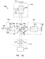
- FIG. 13
- is a schematic of a Mach-Zehnder-type interferometer which can be
used to measure aberrations, which can then be corrected for.
- FIG. 14
- is a schematic of a corrected laser system 340 having a
compensating diffractive element 947 close to gain medium 943.
- FIG. 15
- is a schematic of a corrected laser system 440 having a
compensating diffractive element 948 at point z0 farther from gain
medium 943.
- FIG. 16
- is a schematic of a corrected laser system 540 having a
compensating diffractive element 949 merged into one of the cavity
mirrors.
- FIG. 17
- is a schematic of an interferometer which can be used to measure
aberrations for a laser system in which it is impractical to introduce
light beam 921 through one of the mirrors of laser system 940, the
aberrations which can then be corrected for.
Description of the Preferred Embodiment
In the following detailed description of the preferred embodiments,
reference is made to the accompanying drawings which form a part hereof,
and in which are shown by way of illustration specific embodiments in which
the invention may be practiced. It is to be understood that other embodiments
may be utilized and structural changes may be made without departing from
the scope of the present invention.
Figure 2 is a schematic diagram illustrating an embodiment of a
custom phase-conjugated diffractive mirror laser resonator. Laser beam 100
oscillates in the cavity formed by output mirror 121, laser gain medium 123,
and custom phase-conjugated diffractive mirror 124. Aperture plate 122 and
aperture plate 128 help to block higher-order modes. In one embodiment,
aperture plate 122 and aperture plate 128 are opaque and have a non-reflective
surface. Output laser beam 126 is the laser resonator output. A designer
specifies the phase profile and intensity profile for the fundamental mode 125
of laser beam 100 at a point z along the propagation path of laser beam 100.
In this embodiment, point z is chosen to be at the reflecting surface of output
mirror 121, and thus the phase profile for the fundamental mode 125 is
specified to be a wave with phase profile having values of only 0 and π
radians, corresponding to a flat surface-reflecting mirror for output mirror 121.
The intensity profile for the fundamental mode 125 may be specified by the
designer to be any arbitrary real positive function (a real function has no
imaginary components); e.g., the intensity profile could have an approximately
Cartesian square cross section approximated by graph 120 of Figure 2 and
described by the super-Gaussian equation :
a(x,y) = exp( -(x/ω0)20 ) exp( -(y/ω0)20)
where ω0 is the transverse beam half-width dimension at the point where
intensity drops to 1/e 40 of the maximum intensity along the X or Y axis, and
exp() is the exponential function. Embodiments using smaller values (than the
20 power inside the exp() action used in this case) for the exponential
power may provide less-sharp edges. Even where such sharp edges are
specified, boundary conditions in the laser gain medium and elsewhere in the
laser resonator cavity may prevent the fundamental mode from attaining this
mode profile.
A laser beam with a intensity profile having an approximately
Cartesian square cross section has many uses in industry and research. Uses
include integrated circuit photo-lithography, applications desiring reduced laser
hole burning, laser doppler velocimetry, laser radar, optical memories, optical
information processing and computing, laser bar-code scanning, projection
TV, applications desiring patterns of squares, and laser xerographic printing
and facsimile.
While this example uses a constant phase profile at point z, the
equation for a(x,y) can incorporate any complex-function electric-field profile
(one having both real and imaginary components) as well. The discussion of
Figure 5 below discusses one such embodiment.
The designer then determines the design for the appropriate custom
phase-conjugated diffractive mirror by calculating a wavefront of laser beam
100 at the end of each propagation segment of the propagation path starting
from point z and ending at the reflecting surface of custom phase-conjugated
diffractive mirror 124.
The wavefront of
laser beam 100 at point z
i, the start of the path
though each propagation segment
i (where
i may take the
values 1, 2, 3, ...
n), is characterized by the equation:
where
j is the square root of -1,
u and
v are spatial frequencies, x is a
Cartesian distance in a direction transverse to the direction of propagation, y
is a Cartesian distance in a direction transverse to the direction of propagation
and orthogonal to x, and
A i(u,v) is the angular wave of
a i(x,y) at
point z
i.
The wavefront of
laser beam 100 at point z
i+1 ,the end of each
propagation segment
i, is then calculated using the equation:
where exp() is the exponential function, λ
i is the effective wavelength of
laser beam 100 within propagation segment
i (i.e., λ
i= λ
0 / n
i, where λ
0 is
the free space wavelength of
laser beam 100 and n
i is the index of
refraction of propagation segment
i),
j is the square root of -1, L
i is length
of propagation segment
i along the path of propagation,
u and
v are spatial
frequencies,
du and
dv are integration variables for
u and
v respectively,
sqrt() is the square root function, x is a Cartesian distance in a direction
transverse to the direction of propagation, y is a Cartesian distance in a
direction transverse to the direction of propagation and orthogonal to x, and
Ai(u,v) is the angular wave spectrum of
ai(x,y) at point z
i.
This step is recursively applied to each propagation segment starting
at point z specified by the designer and ending at the surface of custom
phase-conjugated diffractive mirror 124. A mode profile b(x',y') at the
reflecting surface of custom phase-conjugated diffractive mirror 124 is defined
as the final mode profile ai+1(x'y') for the last propagation segment (ending at
the reflecting surface of custom phase-conjugated diffractive mirror 124). A
mirror reflectance t(x',y') is then calculated which reflects the complex phase
conjugate b*(x',y') of said mode profile b(x',y') at said mirror reflecting
surface, using the equation:
t(x',y') = b*(x',y') / b(x',y')
where b*(x',y') is the complex (having real and imaginary components) phase
conjugate of incident mode profile b(x',y').
To illustrate the above-described method, note that Figure 2 shows
three propagation segments. (i takes the values 1, 2, and 3.) The first
propagation segment starts at point z, is represented by length L1, has an
index of refraction n1 (not shown), and ends at point z1 along the propagation
path. The second propagation segment (through laser gain medium 123) starts
at point z1, is represented by length L2, has an index of refraction n2 (not
shown) equal to the index of refraction of the gain medium, and ends at point
z2 along the propagation path. The third propagation segment starts at point
z2, is represented by length L3, has an index of refraction n3 (not shown), and
ends at point z3 at the reflecting surface of custom phase-conjugated
diffractive mirror 124. The above-described method is used to calculate the
mode profile a1(x',y') at point z1; then, using that mode profile as the starting
point, the above described method is used to calculate the mode profile
a2(x',y') at point z2; then, using that mode profile as the starting point, the
above-described method is used to calculate the mode profile a3(x',y') at point
z3 which is at the reflecting surface of custom phase conjugated diffractive
mirror 124. Mode profile b(x',y') is defined as the final mode profile a3(x',y')
for the last propagation segment (ending at the reflecting surface of custom
phase-conjugated diffractive mirror 124). A mirror reflectance t(x',y') is then
calculated which reflects the complex phase conjugate b*(x',y') of said mode
profile b(x',y') at said mirror reflecting surface, using the equation:
t(x',y') = b*(x',y') / b(x',y')
where b*(x',y') is the complex (having real and imaginary components) phase
conjugate of incident mode profile b(x',y).
Those skilled in the art would readily understand that lenses and
other non-planar optical elements inside the cavity can be incorporated in the
calculation by using the appropriate transmittance functions.
The surface elevation of custom phase-conjugated diffractive mirror
124 is then fabricated by known methods (see, e.g., J.R. Leger, M.L. Scott, P.
Bundman, and M.P. Griswold, "Astigmatic wavefront correction of a
gain-guided laser diode array using anamorphic diffrative microlenses," Proc.
SPIE {voL 884}, 82 (1988).) to provide mirror reflectance t(x',y'). One
embodiment coats the surface of custom phase-conjugated diffractive mirror
124 with a reflective coating made from a suitable dielectric material using
materials and methods known to the art. Another embodiment coats the
surface of custom phase-conjugated diffractive mirror 124 with a reflective
coating made from a suitable metallic material using materials and methods
known to the art.
In one embodiment, custom phase-conjugated diffractive mirror 124
is fabricated using a series of photolithographic masks, much in the same way
as modern integrated circuits are. In other embodiments, custom phase-conjugated
diffractive mirror 124 are made from any suitable material (e.g,
plastic, resin, or photoresist) such as is used to mass produce compact disks,
and arrays of custom phase-conjugated diffraction mirrors can be
simultaneously pressed from a single, multiple-image master negative of the
desired mirror surface, much in the same way as modern audio compact-disks
(CDs) or compact disk-read-only-memories (CDROMs) are. These custom
phase-conjugated diffraction mirrors can thus be mass-produced accurately
and inexpensively.
In one embodiment, length L1 is made as small as possible and is
assumed negligible, length L2 is made 7.6 cm, and length L3 is made 102.4
cm. L3 is made long enough that the cavity length achieves sufficient modal
discrimination; this modal discrimination seems to increase until L reaches a
length of one Rayleigh range z0. Optimization studies on super-Gaussian
mode shapes have shown that the modal discrimination is maximized when
the cavity length is approximately one Rayleigh range of the super-Gaussian.
The "Rayleigh range", z0, for a Gaussian distribution is defined by the
equation z0 = π ω0 2 / λ, where ω0 is the transverse beam half-width
dimension at the point where intensity drops to 1/e 2 of the maximum intensity
(e is the exponential function), and λ is the wavelength of the lasing light
wave. For this discussion, the Rayleigh range for a beam with super-Gaussian
power-profile characteristics is defined using this same formula. For large
fundamental-mode beam cross-sections, (ω0 > 0.6 mm), adequate modal
discrimination can require excessively long cavities (greater than one meter,
where λ=1.06 µm).
The reflected laser beam 100, starting at the reflecting surface of
custom phase-conjugated diffractive mirror 124 with mode profile b*(x',y'),
then propagates in the reverse direction along the propagation path to point z.
At point z, laser beam 100 will then have a mode profile a*(x,y), which is the
phase conjugate of the mode profile a(x,y) and traveling in the opposite
direction. In this embodiment, a(x,y) is specified as a wave having phase of 0
or π radians at flat mirror 121, and thus flat mirror 121 will reflect the phase
conjugate of a*(x,y), which is a(x,y). This then reinforces the original
specified mode profile a(x,y) and establishes mode profile a(x,y) as a mode of
the cavity. All other modes suffer increased loss from apertures 122 and 128
in conjunction with the operation of custom phase-conjugated diffractive
mirror 124, and thus a(x,y) becomes the fundamental mode of the cavity.
Figure 3 is a schematic diagram illustrating an embodiment of a
custom phase-conjugated mirror laser resonator similar in many respects to
Figure 2, but with a custom phase-adjustment element 127. One purpose of
custom phase-adjustment element 127 is to enhance the modal discrimination
of the laser resonator system. Another purpose of custom phase-adjustment
element 127 is to introduce varying amounts of phase shift into various
portions of the transverse cross section of laser beam 100. In this
embodiment, custom phase-conjugated mirror 124 may, but need not, be a
diffractive mirror.
To design the components of the custom phase-conjugated mirror
laser resonator comprising a custom phase-adjustment element, the designer
chooses a phase pattern for custom phase-adjustment element 127 to suit the
designer's needs.
In one embodiment, illustrated in Figure 3, custom phase-adjustment
element 127 is transparent and is designed to enhance the modal
discrimination of the laser resonator system by introducing a phase shift
which varies sinusoidally in both Cartesian directions, x and y. In one
embodiment with a phase plate having an orthogonal Cartesian sinusoidal
grating pattern with a frequency of f x = 3.8 mm-1 in the x-direction and f y =
3.8 mm-1 in the y-direction (the phase-adjustment element has a transmittance
t(x,y) that approximates e j cos(2π(fx x+fy y)) and a laser beam wave length of
1.06 µm, the diffractive loss for the second-order mode is increased to 72.9%.
In one embodiment, calculations of the modal discrimination which
would be obtained by a number of different sinusoidal phase patterns for
custom phase-adjustment element 127 are performed. The sinusoidal phase
pattern generating the largest calculated modal discrimation is then used to
fabricate custom phase-adjustment element 127.
The method described above for Figure 2 is recursively applied to
each propagation segment starting at point z specified by the designer and
ending at custom phase-adjustment element 127. The mode profile ai+1(x',y')
at custom phase-adjustment element 127 is then adjusted for the phase shift
introduced by custom phase-adjustment element 127. The method described
above for Figure 2 is then recursively applied to each propagation segment
starting at custom phase-adjustment element 127 and ending at the surface of
custom phase-conjugated mirror 124.
Any custom phase-conjugated mirror can be used for custom phase-conjugated
mirror 124, as long as it reflects the complex phase conjugate
b*(x',y') of the mode profile b(x',y') defined at the reflecting surface of the
mirror. Thus other laser resonator cavities known to the art could benefit
from the addition of a custom phase-adjustment element 127. In this
embodiment, a diffractive mirror is used for custom phase-conjugated
diffractive mirror 124. As described above for Figure 2, a mode profile
b(x',y') at the reflecting surface of custom phase-conjugated diffractive mirror
124 is defined as the final mode profile ai+1(x',y') for the last propagation
segment (ending at the reflecting surface of custom phase-conjugated
diffractive mirror 124); however, in this case, this b(x',y') also accounts for
the phase shift introduced by custom phase-adjustment element 127. A mirror
reflectance t(x',y') is then calculated which reflects the complex phase
conjugate b*(x',y') of said mode profile b(x',y') at said mirror reflecting
surface, using the equation:
t(x',y') = b*(x',y') / b(x',y')
where b*(x',y') is the complex (having real and imaginary components) phase
conjugate of incident mode profile b(x',y').
In one embodiment, the surface elevation of custom phase-adjustment
element 127 is fabricated by known methods (see, e.g., J.R . Leger,
M.L. Scott, P. Bundman, and M.P. Griswold, "Astigmatic wavefront
correction of a gain-guided laser diode array using anamorphic diffractive
microlenses," Proc. SPIE {vol. 884},82 (1988).) to provide the desired
phase adjustments at that element. The surface elevation of custom phase-conjugated
diffractive mirror 124 is also fabricated by similar known methods
to provide mirror reflectance t(x',y'). One embodiment then coats the surface
of custom phase-conjugated diffractive mirror 124 with a reflective coating
made from a suitable dielectric material using materials and methods known
to the art. Another embodiment coats the surface of custom phase-conjugated
diffractive mirror 124 with a reflective coating made from a suitable metallic
material using materials and methods known to the art.
In one embodiment, custom phase-adjustment element 127 is
fabricated using a series of photolithographic masks, much in the same way as
modern integrated circuits are. In other embodiments custom phase-adjustment
element 127 are made from any suitable material (e.g., plactic,
resin, or photoresist) such as is used to mass produce compact disks, and
arrays of custom phase-adjustment elements can be simultaneously pressed
from a single, multiple-image master negative of the desired mirror surface,
much in the same way as modern audio compact-disks (CDs) or compact-disk-read-only-memories
(CDROMs) are. These custom phase-adjustment
elements can thus be mass-produced accurately and inexpensively.
In another embodiment, illustrated in Figure 4, custom phase-adjustment
element 129 is transparent and is designed to enhance the modal
discrimination of the laser resonator system by introducing a phase shift
which varies in a pseudo-random but known manner in both Cartesian
directions, x and y. Other aspects of Figure 4, and the method used to design
components for the embodiment illustrated in Figure 4, are the same as for
Figure 3. In this embodiment, custom phase-conjugated diffractive mirror 124
compensates for the known and pseudo-random phase shifts introduced to the
various portions of the cross section of the mode profile by custom phase-adjustment
element 129.
In one embodiment, calculations of the modal discrimination which
would be obtained by a number of different random phase patterns for custom
phase-adjustment element 129 are performed. In one embodiment, the phase
patterns are generated using different "seeds" in a random number generator.
The random pattern generating the largest calculated modal dicrimination is
then used to fabricate custom phase-adjustment element 129.
Figure 5 is a schematic diagram illustrating an embodiment of a
custom phase-conjugated diffractive mirror laser resonator with two custom
phase-conjugated diffractive mirrors 124 and 124'. One embodiment of this
configuration is conceptually similar to an embodiment shown in Figure 3,
with the modification that flat output mirror 121 is combined with custom
phase-adjustment element 127 to form custom phase-conjugated diffractive
mirror 124'.
The design of one embodiment of this configuration begins in the
same manner as for Figure 2. The method described for Figure 2 is
recursively applied to each propagation segment starting at point z specified
by the designer and ending at the surface of custom phase-conjugated
diffractive mirror 124. A mode profile b(x',y') at the reflecting surface of
custom phase-conjugated diffractive mirror 124 is defined as the final mode
profile ai+1(x',y') for the last propagation segment (ending at the reflecting
surface of custom phase-conjugated diffractive mirror 124). A mirror
reflectance t(x',y') is then calculated which reflects the complex phase
conjugate b*(x',y') of said mode profile b(x',y') at said mirror reflecting
surface, using the equation:
t(x',y') = b*(x',y') / b(x',y')
where b*(x',y') is the complex (having real and imaginary components) phase
conjugate of incident mode profile b(x',y').
The method described for Figure 2 is then recursively applied to
each propagation segment starting at point z specified by the designer and
ending at the surface of custom phase-conjugated diffractive mirror 124'. A
mode profile c(x',y') at the reflecting surface of custom phase-conjugated
diffractive mirror 124' is defined as the final mode profile ai+1(x',y') for the
last propagation segment (ending at the reflecting surface of custom phase-conjugated
diffractive mirror 124'). A mirror reflectance t'(x',y') is then
calculated which reflects the complex phase conjugate c*(x',y') of said mode
profile c(x',y') at said mirror reflecting surface, using the equation:
t'(x',y') = c*(x',y') / c(x',y')
where c*(x',y') is the complex (having real and imaginary components) phase
conjugate of incident mode profile c(x',y').
The surface elevation of custom phase-conjugated diffractive mirror
124 is fabricated by known methods to provide mirror reflectance t(x',y').
One embodiment then coats the surface of custom phase-conjugated
diffractive mirror 124 with a reflective coating made from a suitable dielectric
material using materials and methods known to the art. Another embodiment
coats the surface of custom phase-conjugated diffractive mirror 124 with a
reflective coating made from a suitable metallic material using materials and
methods known to the art.
The surface elevation of custom phase-conjugated diffractive mirror
124' is fabricated by known methods to provide mirror reflectance t'(x',y').
One embodiment then coats the surface of custom phase-conjugated
diffractive mirror 124' with a partially-reflective coating made from a suitable
dielectric material using materials and methods known to the art. Another
embodiment coats the surface of custom phase-conjugated diffractive mirror
124' with a partially-reflective coating made from a suitable metallic material
using materials and methods known to the art. Custom phase-conjugated
diffractive mirror 124' thus becomes the output coupler for the laser resonator.
The reflected laser beam 100, starting at the reflecting surface of
custom phase-conjugated diffractive mirror 124 with mode profile b*(x',y'),
then propagates in the reverse direction along the propagation path to point z.
At point z, laser beam 100 will then have a mode profile a*(x,y), which is the
phase conjugate of the mode profile a(x,y) and traveling in the opposite
direction. In this embodiment, a*(x,y) continues to propagate until it reaches
custom phase-conjugated diffractive mirror 124', where it will have mode
profile c(x',y'). This will then reflect from the reflecting surface of custom
phase-conjugated diffractive mirror 124' with mode profile c*(x',y'), and will
then propagate in the original direction along the propagation path to point z.
At point z, laser beam 100 will now have a mode profile a(x,y). This then
reinforces the original specified mode profile a(x,y) and establishes mode
profile a(x,y) as a mode of the cavity. All other modes suffer increased loss
from apertures 122 and 128 in conjunction with the operation of custom
phase-conjugated diffractive mirror 124, and thus a(x,y) becomes the
fundamental mode of the cavity.
In one embodiment, calculations of the modal discrimination which
would be obtained by a number of various specified phase profiles at various
points z for specified mode profile a(x,y) are performed. The specified phase
profile generating the largest calculated modal discrimination is then used to
fabricate custom phase-conjugated diffractive mirrors 124 and 124'.
In another embodiment, a ring-laser resonator cavity comprising a
custom phase-conjugated diffractive mirror 124 is built. In this embodiment,
point z is specified at a location that is one-half the propagation distance
around the ring from custom phase-conjugated diffractive mirror 124. The
mode profiles around the ring are then calculated in a manner as described for
Figure 2, taking into account the phase change introduced at each bending
node around the ring. Thus accounted for, the complex mode profile (a mode
profile having both real and imaginary components) of the laser beam 100
when it completes the path around the ring will match the starting mode
profile a(x,y).
The laser mode profile can be chosen to have any real positive
function of power distribution and arbitrary phase distribution by proper
design of the mode-selecting mirrors. In addition, the cavity can be optimized
to simultaneously provide a small fundamental mode loss while providing
large losses for higher-order modes (a function called "modal discrimination").
The modal discrimination is influenced by the chosen fundamental-mode
shape, the length of the cavity, and the placement of aperture stops.
The cavity design of the invention preserves high modal
discrimination while allowing use of a shorter cavity length. One
embodiment, shown in Figure 3, comprises a flat output mirror 121, a
diffractive mode-selecting mirror 124, and a sinusoidal phase grating 127.
The designer selects a desired profile for the transverse section of the
fundamental mode at the output port, and calculates the Rayleigh-Sommerfeld
diffraction pattern of this selected profile at the mode-selecting mirror after
passing through the gain medium 123, any other internal optics, and the phase
grating. The diffractive profile of the diffractive mode-selecting mirror
("DMSM") 124 is chosen to reflect the phase conjugate of this distribution.
The reflected light wave will then retrace its path through the phase grating
127 and form the original selected profile at the output mirror 121 (at point
z), thus reinforcing the selected profile and defining it as a mode of the
cavity. Higher-order modes are partially blocked by the 128 placed
at the phase grating 127 and the aperture 122 placed at the output mirror 121,
producing a high loss for those higher-order modes.
A Fox-and-Li analysis (see A.G. Fox and T. Li, Bell Syst. Tech. J.
{40} 453-488 (1961).) of the above cavity with, and without, a phase grating
127 was performed and the optimum characteristics of a phase grating with a
modulation depth of ± 1 radian was studied. Without the grating, a
mode-selecting-mirror cavity (with a cavity length of 1 meter) designed for a
20th-order super-Gaussian beam of transverse half-width ω0 = 0.6 mm was
shown to present a maximum loss to the second-order mode of 48.6 % (which
is due to the design of the DMSM in conjunction with the apertures).
However, when this cavity is reduced in length to 50 cm, the loss to the
second-order mode is reduced to only 25.4 % (a modal discrimination value
which is too small for many high-gain laser designs). There is significant
improvement in modal discrimination of this 50-cm-long cavity when a phase
grating of spatial frequency f is inserted in the cavity along with a
corresponding DMSM. For a phase plate with an orthogonal Cartesian
sinusoidal grating pattern with a frequency of f x = 3.8 mm-1 in the x-direction
and f y = 3.8 mm-1 in the y-direction (the phase-adjustment element
has a transmittance t(x,y) that approximates ej cos(2π(fx x+fy y) ), the diffractive loss
for the second-order mode is increased to 72.9%. This phase-plate spatial
frequency, corresponding to approximately 4.5 periods across the laser beam
transverse cross section, gives the optimal modal discrimination. The
maximum modal discrimination occurs when the grating has a phase shift
corresponding to a sine function. In all of these examples, the 20th-order
super-Gaussian fundamental mode (with square Cartesian beam transverse
cross section) is preserved and suffers negligible loss in the cavity.
Figure 6 is a graph of calculated modal threshold gain versus the
grating frequency for a sinusoidal Cartesian pattern for a phase-adjustment
element.
Figure 7a) is a graph of calculated modal threshold gain versus the
grating frequency bandwidth for a random Cartesian pattern for a phase-adjustment
element.
Figure 7b) is a graph of calculated modal threshold gain versus the
minimum DMSM line- width a random Cartesian pattern for a phase-adjustment
element.
Figure 8 is a graph of a cross section of the phase shift amounts on
a custom phase-conjugating diffraction mirror.
Figure 9 is a schematic of a plan of the phase shift amounts on one
mask for fabricating a custom phase-conjugating diffraction mirror.
Figure 10A is a schematic of a plan of the phase shift amounts on
the first of four masks for fabricating a custom phase-conjugating diffraction
mirror. Figure 10B is a schematic of a plan of the phase shift amounts on the
second of four masks for fabricating a custom phase-conjugating diffraction
mirror. Figure 10C is a schematic of a plan of the phase shift amounts on the
third of four masks for fabricating a custom phase-conjugating diffraction
mirror. Figure 10D is a schematic of a plan of the phase shift amounts on the
fourth of four masks for fabricating a custom phase-conjugating diffraction
mirror. These four figures show schematic of a plan of the phase shift
amounts on four masks for fabricating a custom phase-conjugating diffraction
mirror.
Figures 1A-11D form a schematic of a section showing the process
for fabricating a custom phase-conjugating diffraction mirror. Figure 11A is a
schematic of a section showing the second e-beam mask and a sensitized 2-level
substrate in the process for fabricating a custom phase-conjugating
diffraction mirror. Figure 11B is a schematic of a section showing the
substrate after developing the resist in the for fabricating a custom
phase-conjugating diffraction mirror. Figure 11C is a schematic of a section
showing the substrate after etching in the process for fabricating a custom
phase-conjugaling diffraction mirror. Figure 11D is a schematic of a section
showing the 4-level result substrate in the process for fabricating a custom
phase-conjugating diffraction mirror.
Some applications, such as short-pulse Q-switching require a large
mode cross-section and short cavity length. The same cavity design was
studied with a total length of 10 cm (corresponding to 1/10 Rayleigh range).
Using a phase plate having a grating with a spatial frequency of 10.5 mm-1,
the cavity loss for the second-order mode is 58.3%. This large modal
discrimination is significantly greater than a simple DMSM cavity without a
phase plate with a length of one full Rayleigh range (in this case,
approximately 1 meter).
The addition of a phase plate in a mode-selecting-mirror laser
cavity permits both a reduction in the required cavity length and an increase
in modal discrimination.
Phase-Adjusting Elements
The vast majority of commercial lasers utilize a stable Fabry-Perot
resonator to establish the laser mode. Although the Fabry-Perot resonator
design produces a low-loss fundamental mode, it has several inherent
disadvantages. First, the losses to the higher-order spatial modes are also
fairly low, making it difficult to insure operation in a single spatial mode. In
addition, the transverse dimensions of the fundamental mode laser beam are
usually small, reducing the amount of power that can be extracted from the
gain medium. Increasing the transverse dimensions of the fundamental-mode
laser beam reduces the modal discrimination between the fundamental mode
and the higher-order modes to an unacceptable level. Finally, using a
Gaussian profile for the fundamental mode may not be ideal for applications
that require uniform illumination.
Unstable resonators can support transverse dimensions of the
fundamental-mode laser beam while simultaneously preserving adequate
higher-order mode discrimination. However, these resonators have inherently
"lossy" fundamental modes, and are not suitable for low-gain laser systems.
In addition, they often have an obstructed output aperture that an
undesirable near-field pattern (the power-distribution profile as measured near
the output port of the laser cavity).
Recently, a variety of laser cavities have been demonstrated that use
more sophisticated optics to tailor the fundamental-mode shape and increase
the modal discrimination between adjacent spatial modes. These include
variable-reflectivity mirrors, circular graded phase mirrors, and diffractive
mode-selecting mirrors. The last two methods allow the designer to tailor the
mode profile to any desired shape (although Bélanger's beam has only circular
symmetry), and have been used to generate super-Gaussian fundamental
modes with exceedingly flat tops. However, large modal discrimination
between spatial modes seems to occur when the cavity length is
approximately one Rayleigh range of the super-Gaussian. Thus, for laser
beams with larger transverse dimensions, these methods can result in very
large cavity lengths, thus compromising mechanical stability and increasing
the pulse length for Q-switched operation.
A variation of the diffractive mode-selecting mirror cavity is
described that significantly increases the modal discrimination while reducing
the required cavity length. The cavity, shown in Figure 3, contains a
diffractive mode-selecting mirror 124 on one end and a flat mirror 121 on the
other end. A transparent phase plate 127 is placed between these two mirrors
to (a) increase the modal discrimination, (b) increase the output power, (c)
decrease the cavity length, and (d) increase the allowed diameter of the laser
beam mode. The maximum feature size on the DMSM, however, must be
made smaller to compensate for the higher spatial frequencies on the phase
front at the mirror due to the phase plate.
The design of the cavity proceeds in much the same way as the
simple diffractive mode-selecting mirror. The designer first chooses the
desired amplitude and/or phase profile of the fundamental mode at any
convenient longitudinal location, (e.g., one such location is at the
flat output
mirror 121, where the complex light field is everywhere real). The resulting
field of the selected profile propagated through the gain medium 123 (and any
other internal optics) to the phase plate is calculated by the
Rayleigh-Sommerfeld diffraction formula,
where exp() is the exponential function, λ
i is the effective wavelength of
laser beam 100 within propagation segment
i (i.e., λ
i = λ
0 / n
i, where λ
0 is
the free space wavelength of
laser beam 100 and n
i is the index of refraction
of propagation segment
i ),
j is the square root of -1, L
i is length of
propagation segment
i along the path of propagation,
u and
v are spatial
frequencies,
du and
dv are integration variables for
u and
v respectively, sqrt(
) is the square root function, x is a Cartesian distance in a direction transverse
to the direction of propagation, y is a Cartesian distance in a direction
transverse to the direction of propagation and orthogonal to x, and
Ai(u,v) is
the angular wave spectrum of
ai(x,y) at point z
i, multiplied by the phase
transmittance of the plate e
(j(x,y)), and then propagated the remaining
distance to the diffractive mode-selecting mirror.
The reflectance of the diffractive mode-selecting mirror is then
chosen to return the phase conjugate of this calculated distribution. The
diffractive mode-selecting
mirror 124 with the chosen reflectance is fabricated
using known methods; see, e.g., J.R. Leger, M.L. Scott, P. Bundman, and
M.P. Griswold, "Astigmatic wavefront correction of a gain-guided laser diode
array using anamorphic diffractive microlenses,"
Proc. SPIE {vol. 884}, 82
(1988). The phase-conjugate wave will propagate back through the
phase
plate 127 and gain medium 123 (and any other internal optics) to the
output
mirror 121, regenerating the designer-selected original distribution and
establishing it as a mode of the cavity. If the size of the mode-selecting
mirror 124 is made sufficiently large and the two aperture sizes d
1 and d
2 for
apertures 122 and 128 are chosen properly, the loss to this mode can be made
very small and it becomes the fundamental cavity mode. The higher-order
cavity modes are then calculated by solving the integral equation
where the integral kernel
K(x, x') describes the round trip propagation
in the cavity,
Uv(x) are the eigenfunctions of the equation, and γ
v their
corresponding eigenvalues. One embodiment designs a phase plate with a
phase function
exp( (
j(x,y))
that provides the maximum amount of loss to the second-order mode for a
given cavity length.
Referring to Figure 3, modeling experiments were performed using a
laser cavity with element spacing L2 = 20 cm and L3 = 30 cm, resulting in a
total cavity length LT = 50 cm. The fundamental mode was chosen to be a
20th-order super-Gaussian of square cross-section and beam transverse
dimension of 1.2 mm in both the x and y dimensions. The output aperture
122 has size d1 = 1.3 mm, resulting in negligible clipping of the
super-Gaussian. The phase-plate aperture 128 has d2 chosen to be 4 mm to
pass the diffracted super-Gaussian beam with negligible clipping. The
diffractive mode-selecting mirror 124 was assumed to be arbitrarily large.
The first phase plate 127 studied was a simple phase grating with
(x,y) = m sin (2 π fg x), where m is the modulation index and fg is the
phase plate grating frequency. The loss to the fundamental mode in this case
was always less than 0.1 %. Figure 6 shows the laser threshold gain gth
required for the second-order mode to overcome the cavity diffractive loss.
gth is related to the cavity loss ℓ by gth = 1 / ( 1-ℓ ), so that a threshold gain
of unity corresponds to a "lossless" cavity.
Threshold gains were calculated for a phase plate grating 127 with
m = 1 and a variety of frequency values fg. A grating frequency fg = 0
corresponds to a simple diffracive mode-selecting mirror cavity, and has a
threshold gain gth = 1 / (1-ℓ) = 1.4 (or a loss ℓ = 28 %). This value can
be improved markedly by increasing the grating frequency to approximately 4
cycles/mm, where gth = 1 / (1-ℓ) = 3.7 (corresponding to a loss of 73%).
Increasing the frequency past this point decreases the modal discrimination.
This is expected, since for a sufficiently high frequency, the different orders
of the grating do not overlap. The diffractive mode-selecting mirror then
simply consists of copies of the simple mode-selecting mirror at each of the
diffraction orders. The effects of grating translation and modulation depth
were also studied. Modal threshold gains as large as gth = 1/ (1-ℓ) = 6.9
were observed for phase modulation depths m = 11 radians.
It was postulated that the degree of modal discrimination was
related to the angular plane wave spectrum incident on the mode-selecting
mirror. To test this, a series of experiments was performed using random
phase plates with different angular plane wave spectra. Each phase plate was
designed to have an approximately Gaussian angular plane wave spectrum
with the power spectral bandwidth defined as the 1/e2 point of the Gaussian.
Figure 7a shows the increase of threshold gain to the second-order mode with
increasing phase plate bandwidth. These results are from using a phase plate
with random phases. Figure 7a) shows laser gain required to overcome
diffractive losses to the second-order mode as a function of the spatial-frequency
bandwidth of the phase plate. Figure 7b) shows the effect of finite
diffractive mode-selecting mirror linewidth on the threshold gain of the
fundamental and second-order modes for two different bandwidths Δf.
The error bars show the statistical variation in the simulation. Very
high modal discrimination can be obtained by presenting the diffractive
mode-selecting mirror with a sufficiently intricate light field . The price paid
for this increased modal discrimination is an increase in intricacy of the
mode-selecting mirror. Figure 7b shows the effect of mode-selecting mirror
linewidth quantization on the modal gains of the fundamental and
second-order mode. For fundamental-mode losses of approximately 0.1 %,
features as large as 5 µm can be used for the low-bandwidth phase mask (18
mm-1), whereas 1.7 µm features are required for a high-bandwidth phase
mask (53 mm-1).
Finally, an embodiment implemented a very short (LT = 10 cm)
laser cavity containing a random phase plate with a bandwidth of 44 mm-1.
The phase mask was placed in the center of the cavity as in Figure 4 (L2 = 5
cm, L3 = 5 cm), and a 20th-order super-Gaussian chosen as the fundamental-mode
profile. A mode-selecting mirror was designed with a minimum feature
size of 2 µm and 16 phase quantization levels. The resulting fundamental
cavity mode profile is shown in Figure 4 at graph 120, for a 1.2-mm beam
size. Graph 120 shows the theoretical two-dimensional fundamental-mode
intensity profile of a 10-cm laser cavity containing a random phase plate.
The finite linewidth and phase quantization of the mode-selecting
mirror produce small non-uniformities in the beam profile and result in a
fundamental-mode loss of approximately 1.3%. The gain required to
overcome the losses to the second-order mode was 5.1 (corresponding to a
loss of greater than 80%). For comparison, a stable Fabry-Perot cavity with
the same cavity length, beam size, and fundamental mode loss has a
second-order modal gain of only 1.08, corresponding to a loss of just 7.2%.
If a modal gain of 2.0 is sufficient to discriminate against the
second-order mode (corresponding to a loss of 50%), beam diameters of up to
4.5 mm can be used in this 10-cm-long cavity. It is therefore possible to
extact a large amount of power from the gain medium, while still maintaining
a very small cavity length.
In conclusion, a new type of laser resonator was implemented that
employs an intra-cavity phase plate and a diffractive mode-selecting mirror to
produce large-diameter fundamental modes in a short cavity. The intensity
profile of the fundamental mode can be chosen to suit the application, and the
loss to higher-order modes designed to effectively insure single-spatial-mode
operation.
A Laser Using Two Custom Phase-Conjugated Diffractive Mirrors
A diffractive laser cavity mirror is described in the discussion for
Figure 2 and Figure 5 that can tailor the laser mode profile in amplitude and
phase. An embodiment of this diffractive element is shown in Figure 2 for a
square, flat-top fundamental mode. The mirror had a theoretical fundamental
mode loss of only 0.001 and a second-order mode loss of 0.57, resulting in
high modal discrimination. The fabricated mirror was tested in a Nd:YAG
laser system. The resulting square flat-top mode had an RMS flatness of
1.5% of maximum and a large discrimination against higher-order modes.
Conventional spherical mirrors are used in virtually all modern laser
resonators. Although the resulting Gaussian mode shape is sometimes
desirable, there are many applications where a different shape may be more
appropriate. In addition, the modal discrimination of adjacent transverse
modes is often small, and it is desirable to maximize this modal
discrimination while maintaining a large mode volume. Amplitude spatial
filtering has been used to produce flat-top laser mode profiles, see V.
Kermene, A. Saviot, M Vampouille, B. Colombeau, C. Froehly, and T.
Dohnalik, "Flattening of the spatial laser beam profile with low losses and
minimal beam divergence," Opt. Lett. {17}, 859 (1992). More intricate
mirror shapes have been used to tailor the modal profile of diode laser arrays
and CO2 lasers. The invention extends this latter technique using diffractive
optical elements to tailor the fundamental mode of a Nd:YAG laser. In
addition, careful choice of cavity length and modal filters can provide large
modal discrimination.
The laser cavity shown in Figure 5 consists of two diffractive
mode-selecting mirrors spaced by a distance L T, the sum of all L 1for each
propagation segment in the propagation path.
The design of the diffractive mirrors is chosen to establish the
desired mode as the fundamental mode of the resonator system. Let the
desired amplitude and phase of the mode just to the left of z be described by
ai(x,y), where
ai(x,y) is a complex function. This can be expressed
equivalently in terms of its angular-plane wave spectrum
Ai (u,v) as
where
j is the square root of -1,
u and
v are spatial frequencies, x is a
Cartesian distance in a direction transverse to the direction of propagation, y
is a Cartesian distance in a direction transverse to the direction of propagation
and orthogonal to x, and
Ai (u,v) is the angular wave of
ai (x,y) at
point z
i.
The wavefront of
laser beam 100 at point z
i+1, the end of a
propagation segment
i, is then calculated using the equation:
where exp() is the exponential function, λ
i is the effective wavelength of
laser beam 100 within propagation segment
i(λ
i = λ
0 / n
i, where λ
0 is the
free space wavelength of
laser beam 100 and n
i is the index of refraction of
propagation segment
i),
j is the square root of -1, L
i is length of
propagation segment
i along the path of propagation,
u and
v are spatial
frequencies,
du and
dv are integration variables for
u and
v respectively, sqrt(
) is the square root function, x is a Cartesian distance in a direction transverse
to the direction of propagation, y is a Cartesian distance in a direction
transverse to the direction of propagation and orthogonal to x, and
Ai(u,v) is
the angular wave spectrum of
ai(x,y) at point z
i .
The distribution at the reflecting surface of
mirror 124 is given by
recursive application of the above equations for the propagation path.
If the
mirror 124 is constructed with a reflectance t
2(x',y') of
t
2(x',y') = {b*(x',y')}/{b(x',y'},
where * indicates the complex conjugate, the return wave is given by
Propagation back to z results in
If now the mirror reflectance of 124' is chosen to be
t1(x,y) = {c(x,y)}/{c*(x,y)},
the original distribution a(x,y) has reproduced itself after one round-trip in the
laser cavity, thereby establishing itself as a mode of the system.
Since the reflectances of the two mode-selecting mirrors are
phase-only, they can be easily fabricated as diffractive optical elements. By
making these elements sufficiently large, diffractive losses can be kept to a
minimum and the loss to the fundamental mode can be very small. This
phase-conjugate cavity is reminisent of resonaors based on Brillouin
scattering or four-wave mixing, see J. Auyeung, D. Fekete, A. Yariv, and
D.M. Pepper, IEEE J. Quantum Electron. {QE-15}, 1180 (1979). Note,
however, that the mode-selecting mirror phases are fixed, so this low-loss
imaging only occurs for the desired fundamental mode. The diffractive mirror
can be designed to be "lossy" to higher-order modes, making it an effective
filter for fundamental-mode operation.
Because diffractive mirrors can be fabricated for virtually any phase
profile, the geometric shape of the mode as well as its amplitude and phase
profile are entirely arbitrary. To demonstrate the flexibility of this technique,
a square-shaped mode with approximately uniform amplitude and phase a(x,y)
given by a super-Gaussian of order 20 was generated:
a(x,y) = exp(-(x/ω0)20 ) exp(-(y/ω0)20 )
where ω0 is 0.6 mm, and is the transverse beam half-width dimension at the
point where power drops to 1/e 40 of the maximum power, exp() is the
exponential function. It is apparent that mirror 124' of Figure 5 can be
replaced by a plane mirror 121 of Figure 2, and only a single element needs
to be fabricated. The phase of mirror 124 is calculated by using the above
method for the chosen cavity length, see J.R. Leger and G.J Swanson,
"Optical device for laser coupling and coherent beam combining," U.S.
Patent # 5,033,060 (1991) and J.R. Leger and X. Li, "Modal properties of an
external diode-laser-array cavity with phase conjugate optics," Bulletin of the
American Physical Society {37}, 1212 (1992). A diffractive optical element
is then produced by performing a "modulo-2π" operation on the phase
function and quantizing the result into sixteen levels. The phase profile of the
diffractive element is shown in Figure 8.
A diagram of a Nd:YAG laser cavity is shown in Figure 2.
The laser cavity consists of a partially-reflecting flat output mirror
121, a 100%-reflecting mode-selecting mirror 124, and a flashlamp-pumped
Nd:YAG laser medium 123. Both mirrors have adjustable apertures 122 and
128 to control their size. A Fox-and-Li analysis of the laser modes was
performed to study the effect of the mirror phase quantization, laser cavity
length, and mirror aperture sizes on the mode shape and mode loss. Initial
designs of the mode-selecting mirror using four and eight phase-quantization
levels resulted in fundamental modes with excessive ripple in the flat-top
region. The theoretical mode produced by a sixteen-level element was very
close to the ideal 20th-order super-Gaussian, with sharp sidewalls and an
RMS ripple of less than 1.5% in the flat-top region. The minimum line width
for this 16-level approximation is 50 µm, making fabrication quite
straightforward. Since the smallest features at the edge of the phase function
in Figure 8 are 150 µm, this 50 µm sampling is more than adequate.
The cavity length and mode-selecting mirror size were then
optimized by calculating the modal loss for the two lowest-order modes as a
function of mirror separation and diffractive mirror size. (See, e.g., J.R.
Leger, D. Chen, and Z. Wang, Opt. Lett.{19}, 108-110 (1994).)
For each mirror spacing, a new mode-selecting mirror was
calculated to produce the same desired fundamental mode. The round-trip
intensity loss of the two-dimensional mode was determined by calculating the
eigenvalue of a specific one-dimensional mode γv, and using: loss = 1 - γ v 4.
For mode-selecting mirror sizes greater than approximately 4 mm,
the loss to the lowest-order mode is negligible (<0.0001). The loss to the
next lowest-order mode is seen to peak at a distance z0, where as above,
Rayleigh range
LT = π ω0 2 / λ
is the Rayleigh range of a conventional Gaussian beam. For the
that was conducted, ω0 = 0.6 mm, λ = 1.06 µm, and LT = 1.07 meters.
When the increased index of the YAG crystal in part of the cavity (index of
refraction n = 1.8 over 10 cm) is accounted for, the resultant cavity length is
1.10 meters.
From experiments (see J.R. Leger, D. Chen, and Z. Wang, Opt. Lett.{19}, 108-110 (1994).), it is apparent that the maximum modal
discrimination is achieved for small mode-selecting mirrors. However, small
mirror sizes tend to produce a mode with less steep sidewalls. This is to be
expected, since the higher harmonics from the square-mode diffraction are
clipped by the mirror. In one embodiment, a mode-selecting mirror size of 8
mm was therefore chosen as a compromise between modal discrimination and
desired mode shape.
The finite output mirror has very little effect on the shape or loss of
the fundamental mode for mirror sizes greater than 1.2 mm, as expected. The
loss to the second-order mode is significant and increases with a reduced
output mirror size. For the 1.2-mm mirror used in the case study, the
fundamental mode loss is 0.001 and the second-order mode loss is 0.57. This
substantial loss difference makes it possible to pump the laser hard while still
maintaining single-spatial-mode operation.
The mode-selecting mirror was fabricated by a four-step
mask-and-etch process, see J.R. Leger, M.L. Scott, P. Bundman, and M.P.
Griswold, "Astigmatic wavefront correction of a gain-guided laser diode array
using anamorphic diffractive microlenses," Proc. SPIE {vol. 884}, 82
(1988). This procedure resulted in a 16-level phase element with a profile
that approximated the phase. Figure 9 shows one of the four e-beam masks
fabricated to produce the element. Since the smallest features on any of the
masks were only 50 µm in size, wet chemical etching was used. This gave a
very controllable etch rate and produced an optically smooth surface.
The performance of the diffractive mode-selecting mirror was
studied first outside the laser cavity. A highly expanded continuous-wave
("cw") Nd:YAG laser was used to illuminate a 1.2 mm by 1.2 mm square
aperture with a uniform plane wave. The mode-selecting mirror was placed
1.10 meters behind this aperture, and the reflected wave studied after
propagation back to the square aperture. The mirror produced a very
well-defined square shape. The modal reflectivity was measured by
comparing the power in this square image (integrated over a slightly larger
square area of 1.3 mm by 1.3 mm) to the incident power. After compensating
for the imperfect reflectivity of the gold coating, the modal reflectivity was
measured to be 98% to 99%.
The performance of the mode-selecting mirror inside a laser cavity
was studied and tested next. The laser cavity was set up as in Figure 2 with a
pulsed single-tube flash lamp pumping the YAG rod. The pulse rate was kept
below 2 Hz to reduce thermal effects on the laser rod; interferometric
measurements of the rod by a HeNe probe beam showed these thermal
aberrations to be negligible.
The shape of the mode intensity was measured by a linear CCD
camera and frame grabber. It was discovered experimentally that slightly
better mode shapes were produced using output apertures 122 having aperture
sizes between 1.7 mm and 2.0 mm. An embodiment used an output aperture
122 of 2.0 mm, and a corresponding mode-selecting mirror aperture 128 of 16
mm. The RMS flatness across the top of the measured beam is 1.5% of the
peak value.
The square shape of the mode schematically represented in graph
120 of Figure 2 was virtually unaffected by the shape of the apertures, even
when circular- and diamond-shaped apertures were used. Some degradation
of the sidewall steepness was noticed when the output aperture was reduced to
below 1.5 mm, but the size of the mode remained relatively unchanged.
Larger output apertures were observed to permit multi-spatial mode operation
at higher powers, as expected.
In summary, a diffractive mode-selecting mirror was designed to
produce a square flat-top mode with very high modal discrimination.
Alternate shapes (circular, multiple apertures, etc.) and profiles (tapered,
phase-coded, etc.) can be produced as well. The design was demonstrated
using a flash-lamp-pumped Nd:YAG laser. The experimentally measured
mode shape is very close to the theoretically predicted shape. The
fundamental mode loss from this element was predicted to be 0.001 and
experimentally measured to be 0.01 to 0.02. This very low loss makes the
technique suitable for both low- and high-gain laser systems.
An aspect of the invention provides the introduction of a
low-spatial-frequency phase grating inside a laser resonator employing a
diffractive mode-selecting mirror substantially increases spatial mode
discrimination while presenting negligible loss to the fundamental mode. This
configuration has been used to design a very short, highly selective solid-state
laser cavity.
An arbitrary number of custom phase-adjustment elements similar in
design to custom phase-adjustment element 129 of Figure 4 may be added to
an embodiment of a laser resonator cavity, with the appropriate adjustment to
the affected custom phase-conjugated diffractive mirrors.
In one embodiment, a custom phase-adjustment element is designed
to dynamically adjust phase. In a particular embodiment, a liquid crystal
pixel array (without polarizing elements) is used to implement a custom
phase-adjustment element 129 as shown in Figure 4. The electric field
applied to each pixel adjusts the phase of that pixel. One use for such an
element is to adjust for heat-induced phase changes in the gain medium.
Figure 12A is a schematic of a Michelson-type interferometer 900
which can be used to measure aberrations in laser system 940, which can then
be corrected for. In particular, aberrations and distortions which are caused
by heat absorption in the various elements of laser system 940, and more
particularly in gain medium 943, can be measured and corrected for. Laser
system 940 can be any laser, either of conventional design, or made with
diffractive mirrors such as custom phase-conjugated diffractive mirror 124 of
Figure 4, or a combination system having some conventional and some
diffractive elements.
In normal operation, laser system 940 would be used alone without
any of the other elements shown in Figure 12A. In such normal operation,
pump light 939 would energize gain medium 943, creating an inverted
population needed to cause amplification and lasing in the laser cavity
between mirrors 942 and 944 of laser system 940, and also creating a "waste"
heat buildup in gain medium 943, and thus distortion in the optical path
through gain medium 943 in particular, but also introducing distortion in other
optical path segments. In one embodiment, mirrors 942 and 944 are both
partially transmissive to the wavelength of light beam 921. There is generally
heat buildup to a lesser degree in each of the other elements of laser system
940, with the resultant distortion of the optical path segments.
In one embodiment, gain medium 943 is a crystal rod or slab of
NdYAG. The heat buildup in gain medium 943 is often non-uniform across a
cross-section and along the length of gain medium 943, due to non-uniform
extraction of energy by the laser beam and/or non-uniform coupling of pump
light 939 to gain medium 943, as well as non-uniform heat conduction,
convection, and radiation out of gain medium 943. One primary goal of the
design of optical elements for one embodiment of the present invention is to
preserve the desired phase profile, even in the presence of distortions such as
those due to heat. Another goal of the design of optical elements for one
embodiment of the present invention is to maximize the efficiency of laser
system 940 by designing mirrors (e.g., 942 and 944) and phase adjustment
elements to transfer maximum energy from the entire length and entire cross-section
of gain medium 943 into the laser beam. One factor which should be
taken into account in the design of the optical elements in the path of the
laser beam is the fact that laser system 940 will heat up as a result of waste
heat, and will therefore distort each optical path to a greater or lesser extent.
This heat-up distortion will typically stabilize to a steady-state distortion value
at the operating point of laser system 940, wherein the temperature will be
fixed at each respective point in each element, depending on such factors as
the external temperature, the energy input into each point of each element,
and the energy transferred out of each point of each element. A distortion-compensating
phase element is then designed to provide the complex phase
conjugate of this steady-state distortion value, and thus restore the desired
mode profile for laser system 940.
Referring to the exemplary embodiment shown in Figure 12A, probe
laser 902 emits a light beam into beam expander 905, which includes lenses
904 and 906, and then through iris 908. In one embodiment, the resultant
light beam 920 is of a different wavelength than the operational laser
wavelength of laser system 940, in order to pass more easily through mirror
944 and/or to be more easily be detected at detector 918. In one embodiment,
the wavelength of the probe light beam 920 is 0.8 micrometers, as compared
to the operating laser wavelength of 1.06 micrometers.
The resultant light beam 920 is directed through beam splitter 910
to generate light beam 921 and 922. Light beam 921 is directed into laser
system 940, which is kept at an operating temperature distribution (called
"hot"), for example, by pump light 939. The hot laser system 940 is not
necessarily at a uniform temperature throughout, and is typically hotter in
some areas than in others. Laser system 940 includes mirrors 944 and 942,
gain medium 943, and pump light 939. In one embodiment, one or both
mirrors 942 and 944 are partially transmissive at the wavelength of laser
system 940's normal operating mode, in order to allow laser amplification, but
are more transmissive to the wavelength of the probe light beam 920. (Light
beams 920 through 926 are all the same wavelength) Light beam 921, after
passing through hot laser system 940 is reflected by mirror 941, passes again
through laser system 940, and emerges as light beam 923.
Light beam 922 is directed into laser system 950, which
corresponds to hot laser system 940, but is kept at a room temperature
distribution (called "cold"), and is not heated by, for example, a pump light
source similar to 939. The cold laser system 950 is not necessarily at a
uniform temperature throughout, but is typically at a uniform room
temperature. Laser system 950 includes mirrors 954 and 952, and gain
medium 953 each corresponding to components in laser system 940. Light
beam 922, after passing through cold laser system 950 is reflected by mirror
951, passes again through laser system 950, and emerges as light beam 924.
The present invention can be used in laser systems having
conventional spherical mirrors for mirrors 942 and 944, or one can be
spherical and the other can be flat, or either mirror 942 or 944 can be a
diffractive mirror such as custom phase-conjugated diffractive mirror 124 as
shown in Figure 4 and the other a flat mirror such as mirror 121 of Figure 4,
or both mirrors can be diffractive such as custom phase-conjugated diffractive
mirrors 124 and 124' as shown in Figure 5, or either mirror 942 or 944 can be
a diffractive mirror such as custom phase-conjugated diffractive mirror 124 as
shown in Figure 4 and the other a conventional curved mirror such as shown
for mirror 944 of Figure 12A. U.S. Patent Number 5,255,283 by Bélanger
teaches a circular mode-selecting phase-conjugating mirror used to establish a
radially-tailored circularly-symmetric profile, and the present invention can be
used to correct for distortions in a laser having such a Bélanger-type graded-phase
mirror.
In one embodiment, shown in Figure 12B, mirror 942 is a fully-reflecting
mirror, for example a custom phase-conjugated diffractive mirror
124 designed as described for Figure 2, 3, 4, or 5 elsewhere in this
specification; and mirror 952 is a substantially similar mirror, and mirrors 941
and 951 can be omitted.
In one embodiment, a mode-discriminating custom phase-adjustment
element such as element 127 of Figure 3 or element 129 or Figure 4 is placed
between gain medium 943 and either or both mirrors 942 and 944 (at least
one of which is a mode-shaping diffractive mirror such as mirror 124 of
Figure 4), and a substantially similar corresponding phase- adjustment element
127 or 129 is placed between gain medium 953 and the corresponding mirror
952 and/or 954; thus each element in cold laser system 950 matches the
corresponding element in laser system 940.
In another embodiment, the optical elements of cold laser system
950 act to compensate for the refractive effects of light beams 921 and 923
passing through mirrors 942 and 944 of hot laser system 940.
In another embodiment, all of the optical elements of cold laser
system 950 are replaced by a series of lenses and phase plates which produce
the same optical effect as laser system 950 (which is the equivalent to a cold
version of laser system 940). In such an embodiment, the motivation is to
provide an "ideal" version of the optical path through the optical lenses and
phase plates of this simulated laser system 950 which is to be compared with
laser system 940 by interferometer 900, and a corrective compensating phase-adjustment
element can be calculated and made.
In another embodiment otherwise similar to Figure 12A, all of the
optical elements of cold laser system 950 are removed, and the difference
between the aberration from laser system 940 when laser system 940 is "off'
(or cold) and "on" (or hot) are calculated (i.e., the fringe pattern change is
measured). This method tends to a more complex fringe pattern calculation
than the above methods.
Light beam 923 is directed through beam splitter 910 and the
portion passing though emerges as light beam 925. Light beam 924 is
directed at beam splitter 910 and the portion reflecting as light beam
926. Light beams 925 and 926 then combine to form a resultant interference
pattern, which is then focussed by imaging system 915 onto detector 918.
Imaging system 915 includes lenses 914 and 916 in this embodiment. In one
embodiment, imaging system 915 is adjusted to produce an image at detector
918 of the wavefronts at a point z in laser system 940. In one such
embodiment, detector 918 is comprised of a CCD camera connected to a
computer for analyzing fringes. In one such embodiment, point z is at one
end of the crystal used for gain medium 943, such as is shown in Figure 14.
In another such embodiment, point z is at z0 which is at a distance from the
end of the crystal used for gain medium 943, such as is shown in Figure 15.
In yet another such embodiment point z is at the surface of mirror 942 which
is at a distance from the end of the crystal used for gain medium 943, such as
is shown in Figure 16.
In yet another such embodiment, point z is at the surface of one end
of the crystal used for gain medium 943, and then calculating the effect of
propagating that calculated phase profile to the plane of mirror 942 (using the
method described for Figure 4 above) to calculate and fabricate mirror 949 to
replace mirror 942 such as is shown in Figure 16.
The fringes of the resultant interference pattern represent the
difference in the optical path between the hot laser system 940 and the cold
laser system 950, and thus the distortion due to heat. The fringes of the
resultant interference pattern are converted by standard techniques of
interferometry into an optical phase function for the wavelength of laser
system 940. The particular interference pattern for the wavelength λ1 of
probe beam 920 must be scaled for the operating wavelength λ2 of laser
system 940. In one embodiment, this optical phase function is expressed in
the form a(x,y)= e(j(x,y)), where (x,y) is the two-dimensional phase
distortion, which is typically primarily due to crystal distortions in gain
medium 943.
The distortion-compensating correction plate (e.g., element 948) is
then formed having a complex phase conjugate function of an optical phase
function representative of the first interference pattern. In this context,
"representative of" includes being calculated from the fringe pattern of the
probe wavelength, or being directly fabricated from the fringe pattern.
In order to correct for the phase distortions of gain medium 943, a
distortion-compensating phase-adjustment element is used which presents the
complex phase conjugate (i.e., e(-j(x,y)) at the point z along the optical path
where the optical phase function was calculated. In one embodiment, the
optical phase function is calculated at a point z close to gain medium 943, and
the compensating diffractive optical element 947 is placed close to gain
medium 943 in order to correct for the distortion, as shown in Figure 14. The
resultant corrected laser system 340 includes mirror 944, which is partially
transmissive to the wavelength of laser system 940, gain medium 943,
compensating diffractive optical element 947 placed close to gain medium
943, and a fully reflective mirror for mirror 942. In one such embodiment,
the corrective factor e(-j(x,y)) for the detected distortion is multiplied (or,
equivalently, the -j (x,y) distortion-compensating exponent factor is added
to the exponent factor of the mode-selecting phase adjustment calculated as
described for Figure 2, 3, 4, or 5) into the phase function for a mode-discriminating
phase element (for example, as illustrated in Figure 4, a custom
phase-adjustment element 129) which is already located at the location plane
for compensating diffractive optical element 947.
In another embodiment, the optical phase function is calculated at a
point z0 farther from gain medium 943, and the compensating diffrative
optical element 948 is placed at point z0 from gain medium 943 in order to
correct for the distortion, as shown in Figure 15. In such an embodiment,
optical system 915 is adjusted to focus an interference pattern representative
of the phase distortion as it would appear at point z0, thus allowing a
corrective element having the complex phase conjugate of that phase
distortion to be fabricated and placed at point z0. In another similar
embodiment, the optical phase function is calculated at a point close to gain
medium 943, and a corresponding optical phase function is calculated by
calculating the effect of propagating this optical phase function to point z0 and
the compensating diffractive optical element 948 is placed at point z0 from
gain medium 943 in order to correct for the distortion, also as shown in the
exemplary embodiment of Figure 15. The resultant corrected laser system
440 includes mirror 944 which is partially transmissive to the wavelength of
laser system 940, gain medium 943, distortion-compensating diffractive
optical element 948 placed at point z0 from gain medium 943, and a fully
reflective mirror for mirror 942. In one such embodiment, the corrective
distortion compensating factor e(-j(x,y)) for the detected distortion is
multiplied into the phase function for a mode-discriminating phase element
(such as element 129 of Figure 4) which is already located at the z0 plane for
compensating diffractive optical element 948.
Figure 16 is a schematic of an exemplary embodiment of corrected
laser system 540 having a distortion-compensating diffractive element 949
merged into one of the cavity mirrors. In one such embodiment, the
distortion-compensating surface is added to (or, equivalently, placed onto, or
etched into) an otherwise flat mirror which replaces a flat mirror 942 used
during the measurement steps, and mirror 944 is either a spherical mirror or a
diffraction mirror such as custom phase-conjugated diffractive mirror 124 of
Figure 4. In another such embodiment, a conventional spherical mirror, such
as mirror 944 of Figure 12A is used for mirror 944, and the distortion-compensating
calculation is combined onto a diffractive mirror such as custom
phase-conjugated diffractive mirror 124 of Figure 4 which is used for mirror
942, and the resultant diffractive mirror is used for mirror 949. In another
such embodiment, a flat mirror, such as mirror 121 of Figure 4 is used for
mirror 944, and the distortion-compensating calculation is combined onto a
diffractive mirror such as custom phase-conjugated diffractive minor 124 of
Figure 4 which is used for mirror 942, and the resultant diffractive mirror is
used for mirror 949. These last two embodiments reduce the number of
fabrication steps for mirror 949, since the calculation for the mode-selecting
diffractive phase function can be multiplied by the distortion-compensating
phase function, and a single set of fabrication steps are then used to fabricate
a mirror which combines both functions.
In one embodiment, laser system 940 is tested and corrected in its
production-type case and with all elements, power supplies, enclosures,
fixtures, and positioning devices in place, in order to correct for all distortion
sources within laser system 940. This allows compensation for all heat flows
as they will occur in laser system 940 in normal operation.
In one embodiment, a custom phase-adjustment element 947 is
designed to dynamically adjust phase. In a particular embodiment, a liquid
crystal pixel array (without polarizing elements) is used to implement a
custom phase-adjustment element 129 as shown in Figure 4. The electric
field applied to each pixel adjusts the phase of that pixel. One use for such
an element is to dynamically adjust for heat-induced phase changes in gain
medium 943, for instance due to external factors such as ambient temperature,
or internal factors such as varying laser power outputs.
In another particular embodiment, a series of phase-adjustment
elements 947 are calculated and fabricated for various distortion sources such
as external factors, e.g., ambient temperature, and/or internal factors such as
varying laser power outputs. This series of phase-adjustment elements 947
are then placed on a conventional fixture, such as a rotatable wheel, which
allows the proper particular phase-adjustment element 947 to be positioned
into the laser cavity of laser system 940 for any particular operating condition,
such as various power outputs or various ambient temperatures.
In one embodiment, laser system 940 is tested and corrected using a
lower-quality element for gain medium 943, in order to reduce the costs for
laser system 940, since compensating diffractive optical element 947 or 948 or
949 generated by the distortion-correction method just described can
compensate for some crystal distortions and imperfections. In one such
embodiment, a high-quality crystal, or an optical element which has
substantially identical optical properties, is used for gain medium 953, in
order to generate a fringe pattern which represents the difference between the
high-quality crystal (or other substituted optical element which has
substantially identical optical properties to a higt-quality crystal at the
relevant wavelengths) used for gain medium 953 and the lower-quality crystal
used for gain medium 943. This method can be particularly worthwhile in
those cases where large, high-powered crystals are used, and where the higher
costs of individually correcting and tuning each gain medium 943 crystal can
be justified.
In one embodiment, shown in Figure 12C, only a single element of
laser system 940 is tested and corrected for, for instance gain medium 943.
In one such elements 942 and 944 are removed from laser
system 940, leaving only gain medium 943, and mirror 941 to reflect the
reference light beam; and elements 952 and 954 are removed from laser
system 950, leaving only gain medium 953, and mirror 951 to reflect the
reference light beam. In one such embodiment, a high-quality crystal, or an
optical element which has substantially identical optical properties, is used for
gain medium 953, in order to generate a fringe pattern which represents the
difference between the high-quality crystal (or other substituted optical
element which has substantially identical optical properties to a high-quality
crystal at the relevant wavelengths) used for gain medium 953 and the lower-quality
crystal used for gain medium 943.
In one embodiment, corrected laser system 340 is then replaced into
Michelson-type interferometer 900 in place of laser system 940, and the
above-described correction procedure is iteratively repeated. Since the above-described
correction procedure will tend to change the pattern of energy
transfer from the inverted population in gain medium 943, the heat-induced
distortion will also change as a result of the correction being performed,
giving a different distortion and thus requiring further correction iterations
until a steady-state heat distribution with the best correction desired (as
determined by the number of iterations the designer is willing to perform) is
achieved. In addition, distortions which may be masked by larger-scale
effects such as gain-medium heating initially may become evident as the
sources of those distortions are corrected for.
Figure 13 is a schematic of a Mach-Zehnder-type interferometer
which can also be used to measure aberrations, distortions, and imperfections
in laser system 940, which can then be corrected for. This setup is used in a
manner similar to that described for Figure 12A, above, except that light
beams 921 and 922, rather than being reflected by mirrors 941 and 951
respectively and passing though laser systems 940 and 950 respectively twice
each, pass through (thus traversing gain mediums 943 and 953 only once) to
become light beams 923 and 924 respectively. Calculation of the distortion
phase function and fabrication of the needed phase compensation plates is
performed in a manner corresponding to that described for Figure 12A, above.
Figure 17 is a schematic of an interferometer which can be used to
measure aberrations for a laser system in which it is impractical to introduce
light beam 921 through one of the mirrors of laser system 940, the aberrations
which can then be corrected for. In the embodiment shown, light beam 920
from the probe laser 902 has a wavelength of 0.8 micrometers, while laser
beam 999 of laser system 940 has a wavelength of 1.06 micrometers(µm). In
Figure 17, beam splitter 909 is primarily reflective at 0.8 µm and primarily
transmissive at 1.06 µm Other aspects of the use of the apparatus shown in
Figure 17 are substantially the apparatus in Figure 12C.
One measurement method for using Figure 17 uses a probe light
beam 920 having a wavelength λ1 which is a different wavelength from the
laser wavelength λ2 of laser beam 999 from laser system 940. In this method,
beam splitter 909 is a dichroic beam splitter that is chosen to be anti-reflective
(AR) coated for λ2 and at least partially reflecting for λ1.
A second measurement method for using Figure 17 uses a probe
light beam 920 having a wavelength λ1 which is at a different polarization as
the laser wavelength λ2 of laser beam 999 from laser system 940.
Wavelength λ1 can be, but need not be the same wavelength as λ2. In one
embodiment, λ1 and λ2 are the same wavelength. In this method, beam
splitter 909 is an element which transmits one polarization well and at least
partially inflects another polarization. In one such embodiment, a slab of
conventional uncoated glass is used for beam splitter 909, and positioned at
Brewster's angle with respect to laser beam 999, and light beam 921 is
incident to this beam splitter 909 at the corresponding reflective angle (which
is typically not a right angle as shown in Figure 17, but rather an oblique
angle). In such a system, laser system 940 lases in a TM polarization, and is
not reflected by beam splitter 909. Probe light beam 921 is chosen to be
incident on beam splitter 909 with a TE polarization, causing at least some of
light beam 921 to be reflected into gain medium 943. In the embodiment
shown in Figure 17, "cold" laser system 950 is not a complete laser system, in
that mirror 954 is not used, since mirror 944 is not in the path of light beam
921 or 923.
It is to be understood that the above description is intended to be
illustrative, and not restrictive. Many other embodiment will be to
those of skill in the art upon reviewing the above description. For instance, a
point z specified within the laser cavity is described above, but a person
skilled in the art could use an analogous method starting with point z outside
the cavity. The scope of the invention should, therefore, be determined with
reference to the appended claims, along with the full scope of equivalents to
which such claims are entitled.
One aspect of the present invention provides
a method for making a diffractive mirror for a laser resonator, said
method comprising the steps of:
The method according to
claim 1, wherein:
said second beam mode profile calculating step
comprises the step of calculating:
In one embodiment said mirror reflectance
calculating step comprises the step of:
collapsing portions of said quotient by integer numbers
of a wavelength of said laser beam.
Another aspect of the invention provides
a diffractive mirror for a laser resonator, said laser resonator having
a propagation path, said diffractive mirror made by a method comprising the
steps of:
In one embodiment:
said second beam mode profile calculating step
comprises the step of calculating:
Preferably a surface of
said diffraction mirror is substantially within one wavelength of planar.
Preferably a surface of
said diffraction mirror is fabricated using photolithography or an electron
beam.
In one embodiment said first beam
mode profile a
1(x,y) is a Cartesian super Gaussian of the form
where N > 2 , where M > 2, where A is a constant determined by
said specified beam half-width in said x direction, and where B is a
constant determined by said specified beam half-width in said y
direction.
Preferably M has a value
between 7 and 25, inclusive, and N has a value between 7 and 25, inclusive.
Another aspect of the present invention provides
a method for designing a custom phase-conjugating diffractive
mirror for a laser resonator, said laser resonator having a laser beam, said
laser beam having a propagation path, said diffractive mirror having a
reflection surface, said propagation path comprising a propagation segment
i,
said laser resonator comprising said diffractive mirror and a laser gain
medium, said method comprising the steps of:
A further aspect of the present invention provides
a method for designing a first custom phase-conjugating mirror for
a laser resonator, said laser resonator having a laser beam, said laser beam
having a propagation path, said first custom phase-conjugating mirror having a
reflection surface said propagation path comprising a propagation segment
i,
said laser resonator comprising said first custom phase-conjugating mirror, a
custom phase-adjusting element, and a laser gain medium, said method
comprising the steps of:
calculating a mirror reflectance t(x',y') which reflects a phase
conjugate b*(x',y') of said second mode profile b(x',y') at a surface
of said first custom phase-conjugating mirror, wherein:
t(x',y') = b*(x',y') / b(x',y').
Preferably said custom phase-conjugating
mirror is a custom phase-conjugating diffractive mirror.
The custom phase-adjusting element can comprise a
custom phase-adjusting plate, a heat-compensating adjustment
factor which compensates for a heat distortion in said laser
gain medium, or a second custom phase-conjugating diffractive
mirror.
A further aspect of the present invention provides
a diffractive mirror to be used in a laser resonator, comprising:
a reflective surface, said reflective surface substantially
reflecting a phase conjugate of one particular specified beam having
mode profile a(x,y) at a point z along the propagation path of said
specified beam, said laser resonator including a laser gain medium
and an output coupler, said reflective being at a distance L
from said point z, said reflective surface having a mirror reflectance
t(x',y'), wherein: t(x',y') = b*(x',y') / b(x',y'), wherein b*(x',y') is
the complex phase conjugate of wave b(x',y'), and wherein:
Another aspect of the present invention provides
a laser resonator system comprising:
said second mirror reflects a phase conjugate of a
specified beam, said specified beam has a mode profile a(x,y) at a point
z along the propagation path of said specified beam, a surface of said second mirror is located at a distance L
from said point z,
said second mirror has a mirror reflectance t(x',y'), wherein:
t(x',y') = b*(x',y') / b(x',y')
wherein b*(x',y') is the complex phase conjugate of a mode profile
b(x',y'), and wherein:
The custom phase-adjusting element can comprise a heat-compensating
adjustment factor which compensates for a heat distortion in said laser gain
medium, or a heat-compensating adjustment factor which compensates for a
heat distortion in said laser gain medium.
The laser gain medium can be a semiconductor gain medium or a solid-state
gain medium.
According to one aspect of the present invention a mirror comprising a
diffractive surface, the diffractive surface configured to reconstruct a phase
conjugate of an arbitrary areal mode profile at a chosen surface passing through
a point z, wherein the point z is at a distance from the mirror.
According to another aspect the present invention provides a method for
reconstructing a phase conjugate of an arbitrary areal mode profile at a chosen
surface passing through a point z, comprising the steps of:
The chosen surface can be a plane.
The present invention also provides
The distortion-compensating element can be a diffractive
element.
The method can further comprise the steps of:
calculating a complex phase conjugate function of an
optical phase function calculated from the interference pattern; and
wherein the step of forming comprises forming the distortion-compensating
element having the calculated complex phase conjugate function.
The distortion to be compensated for can be due, at
least in part, to heat.
The present invention can further provide
Preferably the distortion-compensating element is a
diffractive element.
The method can further comprise the steps of:
calculating a complex phase conjugate function of an
optical phase function calculated from the interference pattern; and
wherein the step of forming comprises forming the distortion-compensating
element having the calculated complex phase conjugate function.
The distortion to be compensated for can be due, at
least in part, to heat.
The distortion-compensating element can be fabricated to be placed
substantially adjacent to an end of a gain medium in the laser resonator.
The distortion-compensating element can be merged into a mirror of the
laser resonator.
The present invention can further provide a diffractive element for a
laser resonator, the laser resonator having a propagation path, the diffractive
element made by a method comprising the steps of:
The diffractive element can be a mirror.
The distortion to be compensated for can be due, at least
in part, to heat.
The diffractive element can be a custom phase-adjustment
element.
According to a further aspect the present invention provides
a laser resonator comprising a first distortion-compensating element,
the first distortion-compensating element made by a method comprising the
steps of:
The first distortion to be compensated for can be due, at
least in part, to a first heat distribution.
The laser resonator can further comprise a
second distortion-compensating element, the second distortion-compensating
element made by a method comprising the steps of:
The second distortion to be compensated for can be due, at
least in part, to a second heat distribution.
In one embodiment the laser
resonator has a laser beam having an optical path, and wherein the first
distortion-compensating element and the second distortion-compensating
element are coupled to a fixture which facilitates a positioning of either the
first or the second distortion-compensating element in the optical path of the
laser beam.
The method can further comprise the steps of:
Preferably the first
distortion-compensating element includes a liquid crystal layer.
According to one aspect the present invention provides
The first distortion to be compensated for can be due, at
least in part, to a first heat distribution.
In accordance with an aspect of the present invention
there is provided
a laser resonator comprising a distortion-compensating element, the
first distortion-compensating element made by a method comprising the steps
of:
The first distortion to be compensated for can be due, at
least in part, to a first heat distribution.
The invention can also provide
a method for making a distortion-compensating element for a laser
resonator, the method comprising the steps of:
The invention can further provide
a distortion-compensating element for a laser resonator, the
distortion-compensating element made by a method comprising the steps of:
measuring a distortion in a first laser element; and
forming the distortion-compensating element having a complex
phase conjugate function of an optical phase function representative of the
distortion.
The invention can also provide