EP0853281A2 - Raid apparatus and access control method therefor - Google Patents
Raid apparatus and access control method therefor Download PDFInfo
- Publication number
- EP0853281A2 EP0853281A2 EP97116587A EP97116587A EP0853281A2 EP 0853281 A2 EP0853281 A2 EP 0853281A2 EP 97116587 A EP97116587 A EP 97116587A EP 97116587 A EP97116587 A EP 97116587A EP 0853281 A2 EP0853281 A2 EP 0853281A2
- Authority
- EP
- European Patent Office
- Prior art keywords
- physical disk
- disk unit
- logical volume
- operations
- units
- Prior art date
- Legal status (The legal status is an assumption and is not a legal conclusion. Google has not performed a legal analysis and makes no representation as to the accuracy of the status listed.)
- Withdrawn
Links
Images


Classifications
-
- G—PHYSICS
- G06—COMPUTING; CALCULATING OR COUNTING
- G06F—ELECTRIC DIGITAL DATA PROCESSING
- G06F3/00—Input arrangements for transferring data to be processed into a form capable of being handled by the computer; Output arrangements for transferring data from processing unit to output unit, e.g. interface arrangements
- G06F3/06—Digital input from, or digital output to, record carriers, e.g. RAID, emulated record carriers or networked record carriers
- G06F3/0601—Interfaces specially adapted for storage systems
- G06F3/0602—Interfaces specially adapted for storage systems specifically adapted to achieve a particular effect
- G06F3/061—Improving I/O performance
- G06F3/0613—Improving I/O performance in relation to throughput
-
- G—PHYSICS
- G06—COMPUTING; CALCULATING OR COUNTING
- G06F—ELECTRIC DIGITAL DATA PROCESSING
- G06F3/00—Input arrangements for transferring data to be processed into a form capable of being handled by the computer; Output arrangements for transferring data from processing unit to output unit, e.g. interface arrangements
- G06F3/06—Digital input from, or digital output to, record carriers, e.g. RAID, emulated record carriers or networked record carriers
- G06F3/0601—Interfaces specially adapted for storage systems
- G06F3/0628—Interfaces specially adapted for storage systems making use of a particular technique
- G06F3/0629—Configuration or reconfiguration of storage systems
- G06F3/0631—Configuration or reconfiguration of storage systems by allocating resources to storage systems
-
- G—PHYSICS
- G06—COMPUTING; CALCULATING OR COUNTING
- G06F—ELECTRIC DIGITAL DATA PROCESSING
- G06F3/00—Input arrangements for transferring data to be processed into a form capable of being handled by the computer; Output arrangements for transferring data from processing unit to output unit, e.g. interface arrangements
- G06F3/06—Digital input from, or digital output to, record carriers, e.g. RAID, emulated record carriers or networked record carriers
- G06F3/0601—Interfaces specially adapted for storage systems
- G06F3/0628—Interfaces specially adapted for storage systems making use of a particular technique
- G06F3/0655—Vertical data movement, i.e. input-output transfer; data movement between one or more hosts and one or more storage devices
- G06F3/0658—Controller construction arrangements
-
- G—PHYSICS
- G06—COMPUTING; CALCULATING OR COUNTING
- G06F—ELECTRIC DIGITAL DATA PROCESSING
- G06F3/00—Input arrangements for transferring data to be processed into a form capable of being handled by the computer; Output arrangements for transferring data from processing unit to output unit, e.g. interface arrangements
- G06F3/06—Digital input from, or digital output to, record carriers, e.g. RAID, emulated record carriers or networked record carriers
- G06F3/0601—Interfaces specially adapted for storage systems
- G06F3/0668—Interfaces specially adapted for storage systems adopting a particular infrastructure
- G06F3/0671—In-line storage system
- G06F3/0683—Plurality of storage devices
- G06F3/0689—Disk arrays, e.g. RAID, JBOD
-
- G—PHYSICS
- G06—COMPUTING; CALCULATING OR COUNTING
- G06F—ELECTRIC DIGITAL DATA PROCESSING
- G06F3/00—Input arrangements for transferring data to be processed into a form capable of being handled by the computer; Output arrangements for transferring data from processing unit to output unit, e.g. interface arrangements
- G06F3/06—Digital input from, or digital output to, record carriers, e.g. RAID, emulated record carriers or networked record carriers
- G06F2003/0697—Digital input from, or digital output to, record carriers, e.g. RAID, emulated record carriers or networked record carriers device management, e.g. handlers, drivers, I/O schedulers
Definitions
- the present invention relates to a RAID (Redundant Arrays of Inexpensive Disks) apparatus which allocates a plurality of same logical volumes to a plurality of physical disk units and an access control method there-for, and, more particularly, to a RAID apparatus which prevents access requests and an access unbalanced control method therefor.
- RAID Redundant Arrays of Inexpensive Disks
- Disk storage systems such as a magnetic disk system are used as an external storage system in a computer system.
- a host computer accesses such a disk storage system with a logical volume name that an OS (Operating System) recognizes.
- Logical volumes are allocated in a disk storage system.
- a RAID apparatus has a plurality of same logical volumes allocated on different disk units. When one disk unit fails, another disk unit where the same logical volume of interest is allocated is used. This system can prevent the occurrence of an event that any logical volume becomes unusable due to failure of the associated disk unit.
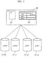
- FIG. 8 is an explanatory diagram of prior art.
- a RAID apparatus comprises a plurality of magnetic disk units 91-1 to 91-4 and a disk controller 90 which controls those disk units.
- FIG. 8 shows the RAID apparatus with a mirror structure which includes four magnetic disk units 91-1 to 91-4.
- a logical volume LM0 is allocated on the magnetic disk unit 91-1.
- the same logical volume LM0 as located on the magnetic disk unit 91-1 is allocated on the magnetic disk unit 91-2.
- a logical volume LM1 is allocated on the magnetic disk unit 91-3.
- the same logical volume LM1 as located on the magnetic disk unit 91-3 is allocated on the magnetic disk unit 91-4.
- the logical volume LM0 can be accessed by using the magnetic disk unit 91-2. Even if the magnetic disk unit 91-3 fails, likewise, the logical volume LM1 can be accessed by using the magnetic disk unit 91-4.
- a high-rank apparatus such as a host computer, issues two or more access requests to the same physical volume.
- a high-rank apparatus such as a host computer
- issues two or more access requests to the same physical volume since one physical disk unit cannot execute two operations at a time, the prior art scheme suffers the inherent problem that some access requests should wait.
- the operation of the magnetic disk units takes a relatively longer time than the operation time of a high-rank apparatus. If some high-rank apparatus frequently issues an access request to the same logical volume, therefore, the number of access request that should wait increases. This increases the time from the issuance of an access request to the end of the requested operation, thus reducing the system access speed.
- a RAID apparatus comprises a plurality of physical disk units for forming same logical volumes, and a disk controller for accessing any physical disk unit which forms a designated logical volume to thereby access the designated logical volume.
- This disk controller has a memory for storing the number of operations, requested to each physical disk unit, for each physical disk unit, and control means for accessing one of the plurality of physical disk units which form the designed logical volume, in accordance with the number of operations.
- An access control method comprises the steps of determining a plurality of physical disk units which form a designed logical volume; and selecting one of the determined physical disk units in accordance with the number of operations requested to the physical disk units.
- the number of operations requested to each physical disk unit is stored for each physical disk unit.
- the physical disk unit which should execute an access request is selected in accordance with the number of the operations.
- the number of the operations requested to each physical disk unit is the number of the operations of each physical disk unit which are currently being performed and are standing by for execution. According to this invention, therefore, the number of actual loads on the physical disk units are always measured.
- the number of the operations (the number of loads) of each of a plurality of physical disk units which hold the same logical volume is determined and a target physical disk unit is selected in accordance with the number of the operations.
- access control is carried out in such a way that the numbers of loads on individual physical disk units which hold the same logical volume become even.
- This scheme can prevent unbalanced access requests to the physical disk units, thus improving the access speed.
- access control can be executed in such a way that the numbers of loads on a plurality of physical disk units become even.
- FIG. 1 presents a principle diagram of this invention.
- physical disk units 11-0 and 11-1 form a same logical volume LM0.
- Physical disk units 11-2 and 11-3 form a same logical volume LM1.
- a disk controller 10 accesses a physical disk unit on which a designated logical volume is allocated to thereby access the designated logical volume.
- This disk controller 10 has a memory 22 for storing the number of operations, requested to each physical disk unit, for each physical disk unit.
- the disk controller 10 further includes a control circuit 21 for accessing one of a plurality of physical disk units which form the designed logical volume, in accordance with the number of the operations.
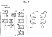
- FIG. 2 is a structural diagram of one embodiment of this invention
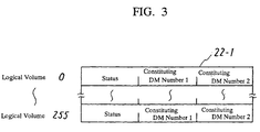
- FIG. 3 is an explanatory diagram of a logical volume structure table according to the embodiment in FIG. 2
- FIG. 4 is an explanatory diagram of a DM management table according to the embodiment in FIG. 2.
- the disk controller 10 is constituted of a magnetic disk controller.
- the disk controller 10 has a channel adapter 20, a resource manager 21, a table storage 22, a main storage 23 and device adapters 24-0 to 24-3.
- the channel adapter 20 exchanges commands/data with a high-rank apparatus like a host computer.
- the resource manager 21 performs control to manage resources.
- the resource manager 21 is constituted of a microprocessor.
- the table storage 22 stores various sorts of tables for the control operation.
- the table storage 22 stores a logical volume structure table 22-1, which will be discussed later with reference to FIG. 3 and a DM management table 22-2 which will be discussed later with reference to FIG. 4.
- the main storage 23 serves to store read/write data, etc.
- the device adapters 24-0 to 24-3 control access to the devices (magnetic disk units) 11-0 to 11-3 in accordance with a request from the resource manager 21.
- the magnetic disk units 11-0 and 11-2 and so forth are connected to the device adapter 24-0.
- the magnetic disk units 11-1 and 11-3 and so forth are connected to the device adapter 24-1.
- the magnetic disk units 11-0 and 11-2 and so forth are also connected to the device adapter 24-2, which is a spare circuit for the device adapter 24-0.
- the magnetic disk units 11-1 and 11-3 and so forth are also connected to the device adapter 24-3, which is a spare circuit for the device adapter 24-1.
- the magnetic disk units 11-0 to 11-3 are each constituted of a well-known magnetic disk storage device.
- the magnetic disk unit 11-0 forms the logical volume LM0.
- the magnetic disk unit 11-1 also forms the logical volume LM0.
- the magnetic disk unit 11-2 forms the logical volume LM1.
- the magnetic disk unit 11-3 also forms the logical volume LM1.
- This structure is a RAID-1 mirror structure in which the individual logical volumes LM0 and LM1 are doubled. That is, two identical volumes are provided for each logical volume.
- the channel adapter 20 When receiving an access request from the high-rank apparatus, the channel adapter 20 issues a device access request to the resource manager 21. Upon reception of the device access request, the resource manager 21 determines a device access path and requests the associated device adapter of performing the operation.
- the device adapter queues an operation for each magnetic disk unit, and accesses the magnetic disk units in the queued order.
- the device adapter When starting access to a magnetic disk unit, the device adapter issues a data transfer request to the resource manager 21.
- the resource manager 21 assigns an area in the main storage 23 and permits the device adapter to execute data transfer. As a result, the device adapter transfers data from the magnetic disk unit to the main storage 23.
- the resource manager 21 When informed of the end of data transfer by the device adapter, the resource manager 21 permits the channel adapter 20 to perform a data access. Consequently, the channel adapter 20 transfers data in the main storage 23 to the high-rank apparatus in a read process. In a write process, the channel adapter 20 writes write data from the high-rank apparatus over data in the main storage 23.
- the resource manager 21 releases the area in the main storage 23 in the read process.
- the resource manager 21 writes the data in the main storage 23 back to the associated magnetic disk unit, and then frees the main storage 23.
- This writing is accomplished by staging data in the memory 21.
- write-back is performed on a pair of magnetic disk units which hold the same logical volume.
- the logical volume structure table 22-1 in the table storage 22 stores the statuses and the constituting DM numbers of the individual logical volumes "0" to "255.”
- the status includes structure definition information and mirroring information for each logical volume.
- the mirroring information consists of two bits indicating whether each of a pair of magnetic disk units which has a mirror structure is normal or abnormal.
- the two constituting DM numbers 1 and 2 indicate the number of a pair of magnetic disk units which has a mirror structure.
- the DM management table 22-2 of the table storage 22 stores the statuses, the numbers of loads and the connected DA numbers of the individual logical volumes "0" to "255.”
- the status includes degrade information indicating whether each magnetic disk unit is normal or abnormal and information indicating whether each of a pair of device adapters to which each magnetic disk unit is connected is normal or abnormal.
- the number of loads indicates the number of operations that are requested to each magnetic disk unit. That is, the number of loads indicates the number of operations of each magnetic disk unit which are currently being performed and are standing by for execution.
- the two connected DA numbers 1 and 2 indicate the numbers of a pair of device adapters to which each magnetic disk unit is connected.
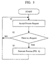
- FIG. 5 is a flowchart for an idling process according to the embodiment in FIG. 2
- FIG. 6 is a flowchart for a request executing process according to the embodiment in FIG. 5
- FIG. 7 is a flowchart for a device path selecting process according to the embodiment in FIG. 6.
- FIGS. 5 through 7 illustrate processes which are executed by the resource manager 21 in FIG. 2. The idling process in FIG. 5 will be discussed first.
- the resource manager (hereinafter called “processor") 21 accepts process requests from the channel adapter 20 and device adapters 24-0 to 24-3.
- the processor 21 checks if the process request is a device access request from the channel adapter (CA) 20. When determining that the process request is a device access request from the channel adapter (CA) 20, the processor 21 terminates the routine after executing a device path selecting process shown in FIG. 7.
- the channel adapter (CA) 20 Upon reception of an access request from a high-rank apparatus, the channel adapter (CA) 20 sends out a device access request to the processor 21.
- the processor 21 determines if the process request is a data transfer request from any one of the device adapters (DA) 24-0 to 24-3.
- the processor 21 When determining that the process request is a data transfer request from the device adapter (DA) 24-0, 24-1, 24-2 or 24-3, the processor 21 assigns an area in the main storage (MS) 23 and then permits the requesting device adapter (DA) to carry out data transfer. Then, the processor 21 terminates the routine.
- MS main storage
- the device adapter (DA) queues operation requests from the processor 21, and accesses the magnetic disk units in the queued order. After the access, the device adapter (DA) generates a data transfer request.
- the processor 21 determines from the end notification which magnetic disk unit (DM) has completed data transfer, and decreases the number of loads of that magnetic disk unit in the DM management table 22-2 by "1."
- the processor 21 permits the channel adapter (CA) 20 to make a data access after which the processor 21 terminates the routine. If it is a read process, the channel adapter 20 transfers data in the main storage 23 to the high-rank apparatus. If it is a write process, the channel adapter 20 writes write data from the high-rank apparatus over the data in the main storage 23.
- CA channel adapter
- the device adapter (DA) After executing the operation and completes data transfer from the target magnetic disk unit to the main storage (MS) 23, the device adapter (DA) generates data transfer end notification and goes to a process for the next operation.
- the processor When determining that the process request is data transfer end notification from the channel adapter (CA), the processor frees an area in the main storage 23 and then terminates the routine, if it is a read process.
- CA channel adapter
- the write-back process is performed. Specifically, after a pair of magnetic disk units constituting a mirror structure are selected, data in the main storage 23 is transferred to the pair of magnetic disk units after which the routine is terminated.
- the processor 21 When receiving an access request from the channel adapter 20, the processor 21 selects a device path and requests the associated device adapter to execute an operation in that device path.
- the processor 21 refers to the logical volume structure table 22-1 in the table storage 22.
- the processor checks the status information of a designated logical volume. Based on mirroring information in the status information, the processor 21 then checks whether each of the pair of magnetic disk units which form the mirror structure is normal or abnormal.
- step S14 When the mirroring information indicates an abnormal event, the processor 21 proceeds to step S14.
- the processor 21 proceeds to step S11.
- the processor 21 reads the numbers of loads A1 and A2 of the pair of magnetic disk units from the DM management table 22-2. The processor 21 then compares the numbers of loads A1 and A2 of the pair of magnetic disk units with each other.
- step S15 When the number of loads A1 of one of the magnetic disk units is equal to or greater than the number of loads A2 of the other magnetic disk unit, it indicates that the load on the former magnetic disk unit is heavier.
- the processor 21 therefore moves to step S15 to select the latter magnetic disk unit with a lighter load.
- step S12 select the former magnetic disk unit with a lighter load.
- the processor 21 refers to the status information of the selected magnetic disk unit (DM1) in the DM management table 22-2. This status information indicates the statuses of the device adapters to which that magnetic disk unit (DM1) is connected.
- the processor 21 determines from the status information that a pair of device adapters to which the selected magnetic disk unit (DM1) is connected are both abnormal, the processor 21 cannot access the selected magnetic disk unit (DM1). Accordingly, the processor 21 writes data indicative of the abnormality of the selected magnetic disk unit (DM1) into the mirroring information in the status information in the logical volume structure table 22-1. Then, the processor 21 proceeds to step S14.
- the processor 21 adds "1" to the number of loads A1 of that magnetic disk unit number in the DM management table 22-2, and then terminates the routine.
- the processor 21 determines from the mirroring information in the logical volume structure table 22-1 which magnetic disk unit is abnormal. When determining that the other magnetic disk unit (DM2) alone is abnormal, the processor 21 proceeds to step S12.
- step S15 When determining that one magnetic disk unit (DM1) is abnormal, the processor 21 proceeds to step S15 to select the other magnetic disk unit (DM2).
- the processor 21 determines from the mirroring information in the logical volume structure table 22-1 which magnetic disk unit is abnormal. When determining that both magnetic disk units (DM1, DM2) are abnormal, the processor 21 makes an error termination.
- the processor 21 refers to the status information of the selected magnetic disk unit (DM2) in the DM management table 22-2. This status information indicates the statuses of the device adapters to which that magnetic disk unit (DM2) is connected.
- the processor 21 determines from the status information that a pair of device adapters to which the selected magnetic disk unit (DM2) is connected are both abnormal, the processor 21 cannot access the selected magnetic disk unit (DM2). Accordingly, the processor 21 writes data indicative of the abnormality of the selected magnetic disk unit (DM2) into the mirroring information in the status information in the logical volume structure table 22-1. The processor 21 then proceeds to step S14.
- the processor 21 adds "1" to the number of loads A2 of that magnetic disk unit number in the DM management table 22-2, and terminates the routine.
- the number of loads (the number of operations) of each magnetic disk unit is stored in the DM management table 22-2 in this manner. This number is incremented for each operation request and decremented for each transfer end (access completion), so that the number of operations (the number of loads) of each magnetic disk unit which are standing by for execution and are currently being processed can always be grasped.
- the processor refers to this number of operations at the time of selecting a device path.
- the processor selects that of a pair of magnetic disk units with a mirror structure which has a smaller number of operations. This scheme makes the numbers of loads of a pair of magnetic disk units even, thus improving the access speed.
- magnetic disk units may be selected alternately every given time.
- access requests from a high-rank apparatus do not come evenly. What is more, single-access times are not even. Therefore, this scheme has a difficulty in performing access control in such a manner that the numbers of loads on a plurality of magnetic disk units which hold the same logical volume become even.
- magnetic disk units may be selected alternately for each access request. Since single-access times are not even, therefore, it is not possible to execute access control in such a way that the numbers of loads on a pair of magnetic disk units become even.
- the number of loads of each magnetic disk unit is monitored directly, making it possible to carry out access control in such a way that the numbers of loads on a pair of magnetic disk units become even.
- the device adapter manages the statuses of magnetic disk units.
- the resource manager would know an abnormality in the selected magnetic disk unit from a response from the associated device adapter which has been made after the resource manager asked the device adapter to perform an operation.
- the selected magnetic disk unit is abnormal, therefore, the prior art requires that the selection and the operation should be performed again.
- the status information indicating the statuses of a pair of magnetic disk units is stored in the logical volume structure table for each logical volume.
- the resource manager selects the magnetic disk unit which is associated with a designated logical volume, the resource manager refers to this status information to find out an abnormal magnetic disk unit.
- the status information indicating the statuses of device adapters to which each selected magnetic disk unit is connected in the DM management table.
- the resource manager selects the magnetic disk unit which is associated with a designated logical volume, the resource manager refers to this status information to find out an abnormal device adapter.
- any failed device adapter informs an error, which makes it possible to update the status of the DM management table.
- this invention has the following advantages.
Abstract
Description
Claims (12)
- A RAID apparatus comprising:a plurality of physical disk units for forming same logical volumes; anda disk controller for accessing any physical disk unit which forms a designated logical volume to thereby access said designated logical volume,said disk controller including a memory for storing a number of operations, requested to each physical disk unit, for each physical disk unit, andcontrol means for accessing one of said plurality of physical disk units which form the designed logical volume, in accordance with said number of operations.
- The RAID apparatus according to claim 1, wherein said control means compares said numbers of operations of a plurality of physical disk units which form said designated logical volumes with each other, and selects that physical disk unit which has a minimum number of operations.
- The RAID apparatus according to claim 1 or 2, wherein said control means includes:a channel adapter circuit for performing interface control with a high-rank apparatus;a device adapter circuit for accessing said physical disk units in accordance with a requested operation; anda resource manager circuit for determining a physical disk unit in accordance with said number of operations in said memory in response to a transfer request from said channel adapter circuit, and requesting said device adapter circuit to perform an operation for accessing said determined physical disk unit.
- The RAID apparatus according to claim 3, wherein said resource manager circuit increments a number of operations of said determined physical disk unit in accordance with a request on said operation and decrements a number of operations of a physical disk unit whose operation has been completed, in accordance with an end of said operation of said device adapter circuit.
- The RAID apparatus according to claim 3 or 4, wherein said memory stores status information indicating statuses of said physical disk units; and
said resource manager circuit refers to said status information to determine whether those physical disk units which form said designated logical volume are normal and selecting a normal physical disk unit. - The RAID apparatus according to claim 3, 4 or 5, wherein for each logical volume, said memory stores information of a plurality of physical disk units which hold said logical volume; and
said resource manager circuit refers to said memory to select a physical disk unit on which said logical volume is allocated. - An access control method for a RAID apparatus comprising a plurality of physical disk units for forming same logical volumes, and a disk controller for accessing any physical disk unit which forms a designated logical volume to thereby access said designated logical volume, said method comprising the steps of:determining a plurality of physical disk units which form a designed logical volume; andselecting one of said determined physical disk units in accordance with a number of operations requested to said physical disk units.
- The access control method according to claim 7, wherein said selecting step compares said numbers of operations of a plurality of physical disk units which form said designated logical volumes with each other, and accesses that physical disk unit which has a minimum number of operations.
- The access control method according to claim 7, wherein said determining step determines said plurality of physical disk units in response to a transfer request from a high-rank apparatus; and
said selecting step includes a step of requesting an operation for accessing said physical disk unit determined in accordance with said number of operations and a step of accessing said physical disk unit in accordance with said requested operation. - The access control method according to any of claims 7 to 9, further comprising the steps of:incrementing a number of operations of said determined physical disk unit, stored in a memory, in accordance with a request on said operation; anddecrementing a number of operations of a physical disk unit whose operation has been completed, in accordance with an end of said operation of said physical disk unit.
- The access control method according to any of claims 7 to 10, wherein said selecting step includes:a step of referring to status information to determine indication of statuses of said physical disk units, stored in a memory, to determine whether those physical disk units which form said designated logical volume are normal; anda step of selecting a normal physical disk unit.
- The access control method according to any of claims 7 to 11, wherein said determining step refers to information of a plurality of physical disk units which form said logical volume, stored in a memory, to determine physical disk units forming said logical volume.
Priority Applications (1)
| Application Number | Priority Date | Filing Date | Title |
|---|---|---|---|
| EP03005705A EP1318447A3 (en) | 1997-01-14 | 1997-09-24 | Raid apparatus and access control method therefor |
Applications Claiming Priority (2)
| Application Number | Priority Date | Filing Date | Title |
|---|---|---|---|
| JP9004427A JPH10198526A (en) | 1997-01-14 | 1997-01-14 | Raid device and its access control method |
| JP4427/97 | 1997-01-14 |
Related Child Applications (1)
| Application Number | Title | Priority Date | Filing Date |
|---|---|---|---|
| EP03005705A Division EP1318447A3 (en) | 1997-01-14 | 1997-09-24 | Raid apparatus and access control method therefor |
Publications (2)
| Publication Number | Publication Date |
|---|---|
| EP0853281A2 true EP0853281A2 (en) | 1998-07-15 |
| EP0853281A3 EP0853281A3 (en) | 1999-05-19 |
Family
ID=11583963
Family Applications (2)
| Application Number | Title | Priority Date | Filing Date |
|---|---|---|---|
| EP97116587A Withdrawn EP0853281A3 (en) | 1997-01-14 | 1997-09-24 | Raid apparatus and access control method therefor |
| EP03005705A Withdrawn EP1318447A3 (en) | 1997-01-14 | 1997-09-24 | Raid apparatus and access control method therefor |
Family Applications After (1)
| Application Number | Title | Priority Date | Filing Date |
|---|---|---|---|
| EP03005705A Withdrawn EP1318447A3 (en) | 1997-01-14 | 1997-09-24 | Raid apparatus and access control method therefor |
Country Status (3)
| Country | Link |
|---|---|
| US (2) | US7080196B1 (en) |
| EP (2) | EP0853281A3 (en) |
| JP (1) | JPH10198526A (en) |
Cited By (5)
| Publication number | Priority date | Publication date | Assignee | Title |
|---|---|---|---|---|
| EP1085406A2 (en) * | 1999-09-15 | 2001-03-21 | Emc Corporation | Load balancing on disk array storage device |
| US6553387B1 (en) * | 1999-11-29 | 2003-04-22 | Microsoft Corporation | Logical volume configuration data management determines whether to expose the logical volume on-line, off-line request based on comparison of volume epoch numbers on each extents of the volume identifiers |
| US7051198B2 (en) | 1998-06-12 | 2006-05-23 | Microsoft Corporation | Logical volume mount manager |
| US8028127B2 (en) * | 2001-07-05 | 2011-09-27 | Hitachi, Ltd. | Automated on-line capacity expansion method for storage device |
| US8990539B2 (en) | 2004-04-30 | 2015-03-24 | Netapp, Inc. | Extension of write anywhere file system layout |
Families Citing this family (16)
| Publication number | Priority date | Publication date | Assignee | Title |
|---|---|---|---|---|
| US6968463B2 (en) * | 2001-01-17 | 2005-11-22 | Hewlett-Packard Development Company, L.P. | System for controlling access to resources in a storage area network |
| US7013364B2 (en) * | 2002-05-27 | 2006-03-14 | Hitachi, Ltd. | Storage subsystem having plural storage systems and storage selector for selecting one of the storage systems to process an access request |
| US7139907B2 (en) * | 2004-04-29 | 2006-11-21 | International Business Machines Corporation | Method and apparatus for implementing distributed SCSI devices using enhanced adapter reservations |
| JP2005338893A (en) | 2004-05-24 | 2005-12-08 | Hitachi Ltd | Data processing system, disk access control method and processing program therefor |
| JP4402565B2 (en) * | 2004-10-28 | 2010-01-20 | 富士通株式会社 | Virtual storage management program, method and apparatus |
| US20060161752A1 (en) * | 2005-01-18 | 2006-07-20 | Burkey Todd R | Method, apparatus and program storage device for providing adaptive, attribute driven, closed-loop storage management configuration and control |
| US7941602B2 (en) * | 2005-02-10 | 2011-05-10 | Xiotech Corporation | Method, apparatus and program storage device for providing geographically isolated failover using instant RAID swapping in mirrored virtual disks |
| US20060218360A1 (en) * | 2005-03-22 | 2006-09-28 | Burkey Todd R | Method, apparatus and program storage device for providing an optimized read methodology for synchronously mirrored virtual disk pairs |
| US20080005382A1 (en) * | 2006-06-14 | 2008-01-03 | Hitachi, Ltd. | System and method for resource allocation in fault tolerant storage system |
| US7971013B2 (en) * | 2008-04-30 | 2011-06-28 | Xiotech Corporation | Compensating for write speed differences between mirroring storage devices by striping |
| TWI367422B (en) * | 2008-05-13 | 2012-07-01 | Jmicron Technology Corp | Raid5 controller and accessing method with data stream distribution and aggregation operations based on the primitive data access block of storage devices |
| US20100011371A1 (en) * | 2008-07-11 | 2010-01-14 | Burkey Todd R | Performance of unary bulk IO operations on virtual disks by interleaving |
| US20100011176A1 (en) * | 2008-07-11 | 2010-01-14 | Burkey Todd R | Performance of binary bulk IO operations on virtual disks by interleaving |
| JP2010195125A (en) * | 2009-02-24 | 2010-09-09 | Nsk Ltd | Electric power steering device |
| JP5252574B2 (en) * | 2009-04-21 | 2013-07-31 | Necシステムテクノロジー株式会社 | Disk array control device, method, and program |
| WO2013093994A1 (en) * | 2011-12-19 | 2013-06-27 | 富士通株式会社 | Storage system, data rebalancing program and data rebalancing method |
Citations (4)
| Publication number | Priority date | Publication date | Assignee | Title |
|---|---|---|---|---|
| JPH03246713A (en) * | 1990-02-26 | 1991-11-05 | Hitachi Ltd | Method and device for controlling storage device |
| EP0485110A2 (en) * | 1990-11-09 | 1992-05-13 | Emc Corporation | Logical partitioning of a redundant array storage system |
| US5375217A (en) * | 1992-03-25 | 1994-12-20 | Ncr Corporation | Method and apparatus for synchronizing disk drive requests within a disk array |
| US5568629A (en) * | 1991-12-23 | 1996-10-22 | At&T Global Information Solutions Company | Method for partitioning disk drives within a physical disk array and selectively assigning disk drive partitions into a logical disk array |
Family Cites Families (17)
| Publication number | Priority date | Publication date | Assignee | Title |
|---|---|---|---|---|
| US932427A (en) * | 1908-07-24 | 1909-08-31 | Frank M Barton | Automatic drain and check valve. |
| JPS60205641A (en) | 1984-03-29 | 1985-10-17 | Fujitsu Ltd | Selection system for in-use physical volume of multiple volume system |
| JPH0388019A (en) * | 1989-08-31 | 1991-04-12 | Toshiba Corp | Data processor |
| US5680574A (en) | 1990-02-26 | 1997-10-21 | Hitachi, Ltd. | Data distribution utilizing a master disk unit for fetching and for writing to remaining disk units |
| JPH03253933A (en) | 1990-03-03 | 1991-11-13 | Fujitsu Ltd | Disk control system in duplex disk controller |
| US5542064A (en) * | 1991-11-21 | 1996-07-30 | Hitachi, Ltd. | Data read/write method by suitably selecting storage units in which multiple copies of identical data are stored and apparatus therefor |
| US5708668A (en) * | 1992-05-06 | 1998-01-13 | International Business Machines Corporation | Method and apparatus for operating an array of storage devices |
| JPH06187101A (en) | 1992-09-09 | 1994-07-08 | Hitachi Ltd | Disk array |
| US5636356A (en) * | 1992-09-09 | 1997-06-03 | Hitachi, Ltd. | Disk array with original data stored in one disk drive and duplexed data distributed and stored in different disk drives |
| JP2912802B2 (en) | 1993-10-14 | 1999-06-28 | 富士通株式会社 | Disk array device failure handling method and device |
| US5537567A (en) * | 1994-03-14 | 1996-07-16 | International Business Machines Corporation | Parity block configuration in an array of storage devices |
| JP3371044B2 (en) * | 1994-12-28 | 2003-01-27 | 株式会社日立製作所 | Area allocation method and disk array access method for disk array |
| US5915095A (en) * | 1995-08-08 | 1999-06-22 | Ncr Corporation | Method and apparatus for balancing processing requests among a plurality of servers based on measurable characteristics off network node and common application |
| US5768623A (en) | 1995-09-19 | 1998-06-16 | International Business Machines Corporation | System and method for sharing multiple storage arrays by dedicating adapters as primary controller and secondary controller for arrays reside in different host computers |
| US5778426A (en) * | 1995-10-23 | 1998-07-07 | Symbios, Inc. | Methods and structure to maintain a two level cache in a RAID controller and thereby selecting a preferred posting method |
| US5819310A (en) * | 1996-05-24 | 1998-10-06 | Emc Corporation | Method and apparatus for reading data from mirrored logical volumes on physical disk drives |
| US5859965A (en) * | 1996-12-17 | 1999-01-12 | Sun Microsystems, Inc. | Method and apparatus for maintaining data consistency in raid |
-
1997
- 1997-01-14 JP JP9004427A patent/JPH10198526A/en active Pending
- 1997-09-17 US US08/932,427 patent/US7080196B1/en not_active Expired - Fee Related
- 1997-09-24 EP EP97116587A patent/EP0853281A3/en not_active Withdrawn
- 1997-09-24 EP EP03005705A patent/EP1318447A3/en not_active Withdrawn
-
2003
- 2003-07-16 US US10/619,597 patent/US7032069B2/en not_active Expired - Fee Related
Patent Citations (4)
| Publication number | Priority date | Publication date | Assignee | Title |
|---|---|---|---|---|
| JPH03246713A (en) * | 1990-02-26 | 1991-11-05 | Hitachi Ltd | Method and device for controlling storage device |
| EP0485110A2 (en) * | 1990-11-09 | 1992-05-13 | Emc Corporation | Logical partitioning of a redundant array storage system |
| US5568629A (en) * | 1991-12-23 | 1996-10-22 | At&T Global Information Solutions Company | Method for partitioning disk drives within a physical disk array and selectively assigning disk drive partitions into a logical disk array |
| US5375217A (en) * | 1992-03-25 | 1994-12-20 | Ncr Corporation | Method and apparatus for synchronizing disk drive requests within a disk array |
Non-Patent Citations (1)
| Title |
|---|
| PATENT ABSTRACTS OF JAPAN vol. 016, no. 042 (P-1306), 31 January 1992 & JP 03 246713 A (HITACHI LTD), 5 November 1991 & US 5 680 574 A (YAMAMOTO ET AL) * |
Cited By (8)
| Publication number | Priority date | Publication date | Assignee | Title |
|---|---|---|---|---|
| US7051198B2 (en) | 1998-06-12 | 2006-05-23 | Microsoft Corporation | Logical volume mount manager |
| EP1085406A2 (en) * | 1999-09-15 | 2001-03-21 | Emc Corporation | Load balancing on disk array storage device |
| EP1085406A3 (en) * | 1999-09-15 | 2004-01-28 | Emc Corporation | Load balancing on disk array storage device |
| US6553387B1 (en) * | 1999-11-29 | 2003-04-22 | Microsoft Corporation | Logical volume configuration data management determines whether to expose the logical volume on-line, off-line request based on comparison of volume epoch numbers on each extents of the volume identifiers |
| US6735603B2 (en) | 1999-11-29 | 2004-05-11 | Microsoft Corp | Logical volume data structure determining configuration status of logical volume based on comparing values of examined volume epoch identifiers on each on-line extent |
| US8028127B2 (en) * | 2001-07-05 | 2011-09-27 | Hitachi, Ltd. | Automated on-line capacity expansion method for storage device |
| US8266375B2 (en) | 2001-07-05 | 2012-09-11 | Hitachi, Ltd. | Automated on-line capacity expansion method for storage device |
| US8990539B2 (en) | 2004-04-30 | 2015-03-24 | Netapp, Inc. | Extension of write anywhere file system layout |
Also Published As
| Publication number | Publication date |
|---|---|
| US20040015658A1 (en) | 2004-01-22 |
| EP0853281A3 (en) | 1999-05-19 |
| US7032069B2 (en) | 2006-04-18 |
| EP1318447A2 (en) | 2003-06-11 |
| US7080196B1 (en) | 2006-07-18 |
| EP1318447A3 (en) | 2004-05-06 |
| JPH10198526A (en) | 1998-07-31 |
Similar Documents
| Publication | Publication Date | Title |
|---|---|---|
| EP0853281A2 (en) | Raid apparatus and access control method therefor | |
| US7213165B2 (en) | Host I/O performance and availability of a storage array during rebuild by prioritizing I/O requests | |
| US5239649A (en) | Channel path load balancing, through selection of storage volumes to be processed, for long running applications | |
| US8266375B2 (en) | Automated on-line capacity expansion method for storage device | |
| US5802345A (en) | Computer system with a reduced number of command end interrupts from auxiliary memory unit and method of reducing the number of command end interrupts | |
| US6708252B2 (en) | Apparatus and method for reallocating logical to physical disk devices using a storage controller, with access frequency and sequential access ratio calculations and display | |
| US5640600A (en) | Storage controller and bus control method for use therewith | |
| US6665740B1 (en) | Logical volume selection in a probability-based job scheduler | |
| JPH034940B2 (en) | ||
| US6122685A (en) | System for improving the performance of a disk storage device by reconfiguring a logical volume of data in response to the type of operations being performed | |
| US6799245B1 (en) | Raid apparatus storing a plurality of some logical volumes on different disk units | |
| US7577957B1 (en) | Multiple jobs per device that are linked via a device record for servicing by different adapters | |
| US6356978B1 (en) | File control device | |
| GB2382183A (en) | Automatic system for assigning physical memory or storage units to logical units to reduce contention | |
| US7536422B2 (en) | Method for process substitution on a database management system | |
| US6732194B1 (en) | Method and apparatus for multi-sequential data operations | |
| US7743180B2 (en) | Method, system, and program for managing path groups to an input/output (I/O) device | |
| US20060036790A1 (en) | Method, system, and program for returning attention to a processing system requesting a lock | |
| JP4708669B2 (en) | Path redundancy apparatus and method | |
| JPH03127157A (en) | Load balance control system for storage device | |
| JPH07334467A (en) | Computer system | |
| JPH10269161A (en) | Load balance control system |
Legal Events
| Date | Code | Title | Description |
|---|---|---|---|
| PUAI | Public reference made under article 153(3) epc to a published international application that has entered the european phase |
Free format text: ORIGINAL CODE: 0009012 |
|
| AK | Designated contracting states |
Kind code of ref document: A2 Designated state(s): DE FR GB |
|
| PUAL | Search report despatched |
Free format text: ORIGINAL CODE: 0009013 |
|
| AK | Designated contracting states |
Kind code of ref document: A3 Designated state(s): AT BE CH DE DK ES FI FR GB GR IE IT LI LU MC NL PT SE |
|
| RHK1 | Main classification (correction) |
Ipc: G06F 3/06 |
|
| 17P | Request for examination filed |
Effective date: 19991109 |
|
| AKX | Designation fees paid |
Free format text: DE FR GB |
|
| 17Q | First examination report despatched |
Effective date: 20021118 |
|
| APBN | Date of receipt of notice of appeal recorded |
Free format text: ORIGINAL CODE: EPIDOSNNOA2E |
|
| APBR | Date of receipt of statement of grounds of appeal recorded |
Free format text: ORIGINAL CODE: EPIDOSNNOA3E |
|
| APBK | Appeal reference recorded |
Free format text: ORIGINAL CODE: EPIDOSNREFNE |
|
| APAF | Appeal reference modified |
Free format text: ORIGINAL CODE: EPIDOSCREFNE |
|
| APBT | Appeal procedure closed |
Free format text: ORIGINAL CODE: EPIDOSNNOA9E |
|
| GRAP | Despatch of communication of intention to grant a patent |
Free format text: ORIGINAL CODE: EPIDOSNIGR1 |
|
| STAA | Information on the status of an ep patent application or granted ep patent |
Free format text: STATUS: THE APPLICATION IS DEEMED TO BE WITHDRAWN |
|
| 18D | Application deemed to be withdrawn |
Effective date: 20100115 |