EP0853461B1 - Improved apparatus for applying x-rays to an interior surface of a body cavity - Google Patents
Improved apparatus for applying x-rays to an interior surface of a body cavity Download PDFInfo
- Publication number
- EP0853461B1 EP0853461B1 EP96938617A EP96938617A EP0853461B1 EP 0853461 B1 EP0853461 B1 EP 0853461B1 EP 96938617 A EP96938617 A EP 96938617A EP 96938617 A EP96938617 A EP 96938617A EP 0853461 B1 EP0853461 B1 EP 0853461B1
- Authority
- EP
- European Patent Office
- Prior art keywords
- balloon
- tube
- cannula
- axis
- interior
- Prior art date
- Legal status (The legal status is an assumption and is not a legal conclusion. Google has not performed a legal analysis and makes no representation as to the accuracy of the status listed.)
- Expired - Lifetime
Links
Images


Classifications
-
- A—HUMAN NECESSITIES
- A61—MEDICAL OR VETERINARY SCIENCE; HYGIENE
- A61N—ELECTROTHERAPY; MAGNETOTHERAPY; RADIATION THERAPY; ULTRASOUND THERAPY
- A61N5/00—Radiation therapy
- A61N5/10—X-ray therapy; Gamma-ray therapy; Particle-irradiation therapy
- A61N5/1001—X-ray therapy; Gamma-ray therapy; Particle-irradiation therapy using radiation sources introduced into or applied onto the body; brachytherapy
-
- A—HUMAN NECESSITIES
- A61—MEDICAL OR VETERINARY SCIENCE; HYGIENE
- A61M—DEVICES FOR INTRODUCING MEDIA INTO, OR ONTO, THE BODY; DEVICES FOR TRANSDUCING BODY MEDIA OR FOR TAKING MEDIA FROM THE BODY; DEVICES FOR PRODUCING OR ENDING SLEEP OR STUPOR
- A61M25/00—Catheters; Hollow probes
- A61M25/10—Balloon catheters
Definitions
- the present invention relates to a miniaturized, low power, programmable x-ray source for use in delivering specifically contoured doses of x-rays to a specified region. More specifically, the invention relates to apparatus and methods for delivering desired x-ray flux to interior surfaces of body cavities.
- X-radiation applied to the soft tissue lining body cavities is known to be useful in the treatment of certain cancers, including cancer of the bladder, vagina and cervix, urethra, uterus, colon and rectum.
- cancers including cancer of the bladder, vagina and cervix, urethra, uterus, colon and rectum.
- the target tissue In an ideal treatment for many conditions, only the surface of the body cavity, i.e., the target tissue, is exposed to the radiation.
- radiation therapy utilizes an external radiation source which directs relatively high energy, and thus tissue-damaging, x-rays toward the patient, so that the x-rays must first penetrate the skin and other tissue of the patient, prior to reaching the tissue lining the body cavity.
- Undesirable radiation of non-target tissue is thus an unavoidable consequence of having a conventional x-ray source located outside the patient's body. Further, the use of relatively high energy, and thus tissue damaging, x-rays are required to insure that a sufficient dose is delivered to the target tissue.
- isodose contour refers to a surface over which the x-ray flux density is substantially constant.
- a uniform dose implies generating an x-ray distribution having an isodose contour that is coincident with the interior surface of the cavity.
- That x-ray source includes an elongated tube extending along a source axis, and has an electron beam generator at one end which generates and directs an election beam along the source axis to the other end and in here it is incident upon a target which is reprone to the beam to generate x-radiation.
- That source can be inserted into a patient's body, and immediately adjacent to a tissue to be treated, and then activated to generate x-rays from within, permitting generation of x-rays from points local to the target tissue.
- the x-rays need not pass through the patient's bone mass, and skin, and other tissue prior to reaching the target tissue.
- One useful apparatus for delivering radiation to the interior surface of a body cavity uses a combination of a miniaturized low power x-ray source of the type disclosed in U.S. Patent No. 5,530,900 , and an inflatable balloon.
- a miniaturized low power x-ray source of the type disclosed in U.S. Patent No. 5,530,900
- an inflatable balloon used as an inflatable balloon.
- This apparatus uses a guidance (or balloon) tube with a balloon affixed to its distal tip, where the balloon stretches the body cavity to a desired known shape, such as a sphere.
- the x-ray source is advanced through the balloon-tube so that its x-ray generating distal tip is positioned at a predetermined location, for example, the center, within the inflated balloon, and then is activated.
- a substantially spherical (when inflated) balloon is positioned in the cavity and inflated, thereby forcing a spherical shape to the defining boundary, and thus the lining.
- a substantially omni-directional x-ray source is positioned at the center of the inflated balloon.
- One important aspect of that approach is the ability to locate the x-ray source at a predetermined location within the body cavity. Inflating the balloon can stretch the body cavity to a known shape, but internal pressures near the cavity can cause the balloon-cavity structure to shift in position relative to the balloon tubes, thereby causing a misalignment between the balloon axis and the axis of the x-ray source. If the x-ray source can not be positioned accurately, it then becomes difficult to deliver a uniform dose to the surface of the body cavity.
- the deflated balloon when packed around the balloon-tube, forms a structure that is relatively large in diameter making insertion into and retraction from body passageways difficult. This is an important factor for relatively small passageways, such as the urethra, into which the structure is inserted for x-ray treatment of the bladder.
- the balloon-tube is typically only partially transmissive of x-rays and interferes with the ability to deliver a specifically contoured dose to the target tissue.
- the radiating tip of the probe can not be placed close to a cavity wall in a manner permitting radiation of local lesion on that wall.
- WO95/3201 is a novelty-only document under A54(3) EPC in respect of the German, Spanish, French, Italian and British designations of this application. It discloses an expandable multi-functional instrument for performing various diverse operative procedures, includes an elongate distensible member having a distal end for being introduced in an anatomical cavity via a relatively small size anatomical opening, and being movable from a non-distended position facilitating introduction through the anatomical opening to a distended position wherein the cross-sectional size of the distensible member is increased, and a plurality of collars disposed on portions of the distensible member for constraining movement of the distensible member portions to the distended position.
- a method of performing an operative procedure in an anatomical cavity includes the steps of introducing a distal end of an elongate distensible member in the anatomical cavity through a relatively small size anatomical opening and moving the distensible member from a non-expanded position to an expanded position.
- US-A-5,442,678 discloses an x-ray source comprising a housing, an elongated tubular probe, a target assembly, and a beam steering assembly.
- the housing encloses an electron beam source, and has elements for generating an electron beam along a beam path.
- the elongated tubular probe extends along a central axis from the housing about the beam path.
- the target assembly extends along the central axis and is adapted for coupling to the end of the probe distal from the housing.
- the target assembly includes a target element positioned along the beam path, wherein the target element is adapted to emit x-rays in a predetermined spectral range in response to incident electrons.
- the beam steering assembly includes a deflection element, a feedback network, and a deflection controller.
- the deflection element deflects the beam from a nominal axis to a selected surface region on the target element in response to a deflection control signal.
- the feedback network includes deflection sensing elements for sensing the deflection of the beam and elements for generating a feedback signal representative thereof.
- the deflection controller couples to the deflection element and to the feedback network and includes elements for generating a deflection control signal in response to the feedback signal.
- the balloon When inflated, the balloon defines a predetermined surface contour disposed about an interior region extending along a balloon attachment axis, or balloon axis, which extends across a diameter of the balloon from the junction of the balloon-tube and the balloon.
- the balloon axis intersects the central axis of the balloon-tube near the distal end of the balloon-tube.
- the cannula may be inserted through a body passageway, e.g., the urethra, so that the distal end of the cannula is positioned near a body cavity, e.g., the bladder, and so that the proximal end of the cannula remains external to the body.
- the balloon-tube and balloon when deflated, may then be inserted through the cannula so that the balloon is positioned beyond the distal end of the cannula and within a body cavity.
- the balloon may then be inflated and thereby stretch the body cavity to a predetermined shape.
- the central and canula axes are normally coaxial.
- the balloon axis and the central axis of the balloon-tube intersect, they are generally not axially aligned immediately following inflation of the balloon. While the balloon is substantially inelastic, the material forming the balloon at the attachment between the balloon and the balloon-tube somewhat flexible, permitting the orientation between the balloon axis and the balloon-tube to be easily changed.
- the angle between the central and balloon axes may be adjusted by rotating the cannula about the point of intersection of the balloon and central axes, thereby permitting adjustment of the central and cannula axes into a desired angular alignment.
- the assembly of an aspect of the invention further includes an alignment mechanism that is operative from the proximal end of the cannula for selectively adjusting the angle between the balloon and cannula axes to a predetermined angular orientation.
- the angle between the balloon and cannula axes is adjustable between zero and 90 degrees.
- the alignment mechanism may include a reference mark, or region, which is detectable (e.g., optically detectable) from the interior of the balloon.
- the reference mark may be located at the intersection of the balloon and the balloon axis opposite the intersection of the balloon and central axes, and the reference mark may be located on the exterior of the balloon in the case of a transparent or translucent balloon, or on the interior of the balloon.
- the position of the reference mark relative to the cannula axis is determinable from within the interior region of the balloon, so that a user can observe the position of the mark relative to the cannula axis, and thus know the angular orientation of the balloon axis relative to the cannula axis.
- the reference mark may fluoresce in response to incident light in a predetermined spectral range.
- light in that spectral range may be directed via a filter to the balloon interior.
- An operator may manipulate the cannula axis relative to the balloon axis of the inflated balloon while monitoring the balloon interior via an output filter at a wavelength associated with the fluorescence, to detect fluorescent light from the reference mark and determine when the cannula axis is aligned with the balloon axis.
- the assembly may also include an inflation assembly disposed near the proximal end of the balloon-tube for controlling the pressure in the interior region of the balloon.
- the inflation assembly may provide a gas flow path extending between a pressure source and the interior channel.
- the balloon when inflated may be spherical. However, the use of balloons having cylindrical, or other shape that may be desired for a particular cavity-to-be-illuminated. Symmetry, or no symmetry at all is also used for various forms of the invention.
- Figures 1 and 2 show an apparatus 10 according to the present invention which is useful for providing radiation treatment to the tissue lining of a body cavity.
- Apparatus 10 includes a balloon-tube 14 having a distal end 16 and a proximal end 20, and includes an inelastic, spherical balloon 12 attached to distal end 16.
- Balloon-tube 14 is hollow and defines an interior channel 22 extending along and about a balloon-tube axis 30.
- Interior channel 22 is connected with an interior region of balloon 12 such that inflation and deflation of balloon 12 is controllable from the proximal end 20 of balloon-tube 14.
- Figure 1 shows balloon 12 inflated and
- Figure 2 shows balloon 12 deflated, with the balloon 12 being collapsed around an axis 13 extending coaxially from axis 30.
- balloon 12 When inflated, balloon 12 defines a balloon diameter 13, a proximal end of which is located at the center of the distal end 16 of the balloon-tube 14 and a distal end of which is at the oppoite side of the balloon.
- Balloon diameter 13 will be referred to herein below as the balloon-attachment axis, or more simply as the balloon-axis.
- the diameter (or balloon axis) 13 is not aligned with the control axis of the balloon-tube 14.
- balloon 12 contains a reference, or fiducial, region or mark 18 at the distal end of balloon axis 13.
- the mark 18 is observable from the interior of the inflated balloon for facilitating alignment of balloon-tube axis 30 and the inflated balloon axis 13, as will be discussed further below.
- reference mark 18 is preferably located where axis 13 intersects the surface of balloon 12 as shown in Figure 1 .
- reference region 18 may include a plurality of marks disposed in a circularly symmetric pattern centered on the distal end of axis 13 and balloon 12. The mark 18 may be located either inside or outside balloon 12.
- balloon 12 contacts the tissue lining a body cavity and therefore is preferably composed of a biocompatable material.
- balloon 12 is an inelastic balloon, meaning that inflation will expand balloon 12 to a predetermined shape and further inflation will not further alter the balloon's shape but will only increase interior pressure, and accordingly, the rigidity of the balloon.
- Balloon 12 is also preferably transparent, so body surfaces and any external reference mark can be viewed from the interior of the inflated balloon.
- the balloon-tube 14 is sized to permit insertion into a cannula which in turn is sized to facilitate insertion into body passageways such as the urethra, and the balloon is preferably chosen so that when deflated, as shown in Figure 2 , the balloon 12 can be packed into a region having a diameter no larger than that of the inner diameter of the cannula, or more preferably no larger than the outer diameter of the balloon-tube 14.
- the apparatus of the present invention may also include an electron-beam (e-beam) activated x-ray source.
- That source may operate at relative low energy as in the range of approximately 10 kV to 90 kV, and relatively small electron beam currents, as in the range of approximately 1 nA to 1 mA.
- e-beam electron-beam activated x-ray source
- Figure 3 shows such an x-ray source 110 which includes an elongated cylindrical probe 114 extending along a reference axis 116 from a housing 112 and having a target assembly 126 at its distal end.
- the housing 112 encloses a power supply 112A.
- the probe 114 is a hollow tube having at its proximal end an electron beam generator (cathode) 122 and an associated high voltage power supply 112A.
- Cathode 122 is located in close proximity to an annular focusing electrode 123 typically at nearly the same potential as the cathode 122.
- the hollow, tubular probe 114, the cathode, grid, and the hole in the anode all extend along an axis 116.
- An associated controller controls the greater of these elements to generate an e-beam, and direct that beam along axis 116 to the target assembly 126.
- the target assembly in response to this incident e-beam, generates x-rays.
- parts of the probe 114 are preferably selectively shielded to control the spatial distribution of x-rays.
- the probe 114 is preferably magnetically shielded to prevent external magnetic fields from deflecting the beam away from the target.
- Kit 210 includes balloon 12, balloon-tube 14, and x-ray probe 114 (housing 112 is not shown).
- Kit 210 further includes an elongated tubular cannula 214.
- Cannula 214 defines an axis 230 and has an inner diameter slightly larger than the outer diameter of balloon-tube 14, such that balloon-tube 14 and balloon 12 when deflated are slidably positionable within an interior channel 222 of cannula 214 so that balloon-tube axis 30 is substantially coaxial with cannula axis 230.
- the walls of cannula 214 includes interior channels which permit flow therethrough of a fluid coolant.
- the walls of cannula 214 also include channels permitting flow of urine from the bladder, as well as the flow of gas into the bladder (so that the bladder can be inflated to facilitate inflation of the balloon 12).
- a proximal end 220 of cannula 214 is integrally mounted to a cooled-cannula water and urine manifold 223 which is supported by a docking clamp (or block) 224 useful for aligning cannula 214 as will be discussed further below.
- Manifold 223 also allows gas (preferably (CO 2 ) to be introduced through the urine channel in order to inflate the bladder. Balloon inflation is accomplished by means of gas inlet 64 as described below.
- the cannula 214 is constructed from surgical steel or other biocompatable material. In use, the cannula 214 is inserted into body passageways, such as the urethra, or surgically made passageways. Since cannula 214 is relatively rigid, balloon-tube 14 may be relatively flexible and may be fabricated from, for example, light weight, thin, plastic.
- FIG 4 shows proximal end 20 of balloon-tube 14 integrally mounted in a pressure-lock module 50, which provides for the introduction of gas pressure into the balloon and subsequent introduction of an endoscope or the x-ray probe into the balloon without losing pressure in the balloon.
- Pressure-lock module 50 defines an interior channel 52 extending from proximal end 20 of balloon-tube 14 to an end 60 of pressure-lock module 50 such that interior channel 52 is connected to and coaxial with interior channel 22 of balloon-tube 14 (shown in Figure 1 ).
- Interior channel 52 is sized such that x-ray probe 114 is slidably positionable within channel 52.
- the balloon-tube 14 is affixed to pressure-lock module 50 by way of a clamp 233.
- Figure 4 shows balloon-tube 14 inserted within cannula 214 such that the distal end 16 of balloon-tube 14 extends beyond a distal end 216 of cannula 214. In this position, balloon 12 is free to expand without being constricted by cannula 214.
- Figure 4 further shows x-ray probe 114 inserted within balloon-tube 14 such that x-ray target 126 is centered within inflated spherical balloon 12.
- Pressure-lock module 50 includes a sealing O-ring 62 for forming an air-tight seal with probe 114 for preventing pressurized gas from escaping inflated balloon 12 when probe 114 is inserted within channel 52.
- O-ring 62 is preferably made of rubber or other resilient material suitable for forming air-tight seals.
- pressure-lock module 50 may include other o-rings distributed in a conventional fashion through module 50 to assist in forming a gas-tight seal with probe 114.
- Pressure-lock module 50 further provides a pressure port 64 which may be coupled to a tank of pressurized gas or a pump (not shown) for controlling inflation and deflation of balloon 12.
- Pressure-lock module 50 further provides gate valve 66 and O-rings 68 for sealing channel 52 and thereby maintaining pressure within balloon 12 when the x-ray probe or an endoscope are not present in o-ring 62.
- Gate valve 66 which is shown in an open position in Figure 4 , is slidably mounted within pressure-lock module 50. In its open position, gate valve 66 does not obstruct channel 52 and allows probe 114 to be inserted into balloon-tube 14. When probe 114 is withdrawn, gate valve 66 can slide downwards such that O-rings 68 and gate valve 66 form a gas-tight seal preventing gas from flowing between the interior of balloon 12 and end 60 of pressure-lock module 50.
- Pressure lock module 50 thus provides several methods for controlling the inflation and deflation of balloon 12 while introducing either the probe or endoscope into the balloon. For example, if balloon 12 is initially deflated, gate valve 66 may be moved downwards to its closed position and a gas pump (not shown) can pump gas through pressure port 64 into balloon 12 until the balloon is inflated to a desired pressure. Gate valve 66 and O-rings 68 prevent any gas from escaping through end 60. Once probe 114, or other such instrument, is inserted into channel 52 such that target end 126 is beyond O-ring 62, gate valve 66 can be retracted to its open position as shown in Figure 4 . The seal formed by O-ring 62 and probe 114 will prevent any gas from escaping the balloon.
- Probe 114 can then be inserted such that target 126 is positioned at a desired location within inflated balloon 12 as shown in Figure 4 .
- This final insertion of probe 114 increases the pressure inside balloon 12 slightly because probe 114 drives some of the gas that was inside channel 22 into balloon 12. This slight increase in pressure is generally negligible and does not interfere with the operation of kit 210. However in some situations, it is desirable to connect a pressure control valve (not shown) to port 64 to maintain constant pressure within balloon 12 as probe 114 is being inserted.
- kit 210 will now be discussed in connection with providing an exemplary radiation treatment to a bladder.
- radiation treatment of other body cavities can be accomplished in a similar manner.
- cannula 214 is inserted into the urethra of a patient such that distal end 216 is positioned near the intersection of a urethra and a bladder 300.
- Proximal end 220 of cannula 214 remains outside the body of the patient.
- the body wall of the patient is shown schematically at 302 in Figure 5A .
- the bladder 300 initially has an irregular shape.
- kit 210 includes a V-guide 410 used for alignment as will be discussed further below.
- V-guide 410 provides a surface bearing a V-shaped groove 412 extending along an axis 430.
- Docking clamp 224 may be fixed to one end of V-guide 410, and manifold 223 may be clamped to docking clamp 224.
- the cannula axis 230 of cannula 214 is parallel to axis 430 of V-guide 410.
- V-guide 410 and cannula 214 are aligned by clamping manifold 223 to docking clamp 224.
- pressure-lock module 50 is positioned on V-shaped groove 412 as shown in Figure 5A .
- the balloon-tube axis 30 of balloon-tube 14 is substantially coaxial with cannula axis 230.
- balloon 12 is deflated and is packed so that it extends along central axis 30 and so that the outer diameter of balloon 12 does not exceed the outer diameter of balloon-tube 14.
- Pressure-lock module 50 is then advanced along groove 412 towards docking clamp 224 so that deflated balloon 12 and balloon-tube 14 are inserted through cannula 214.
- the components are sized so that when pressure-lock module.50 abuts docking clamp 224, the distal end 16 of balloon-tube 14 extends just beyond the distal end 216 of cannula 214 so that balloon 12 extends into the bladder 300.
- Figure 6 shows pressure-lock module 50 abutting docking clamp 224 and balloon 12 inflated so that balloon 12 has stretched bladder 300 to a uniform spherical shape.
- bladder 300 via gas flow in the urine channels of cannula 214) prior to inflation of balloon 12 so that minimal stress is applied to the bladder during inflation of the balloon.
- internal pressures from the patient's body typically cause balloon 12 to shift relative to cannula 214 so that balloon axis 13 is angularly offset with respect to cannula/balloon-tube axes 30, 230.
- Figure 7 shows an endoscope 500 inserted into the balloon 12.
- the misalignment of axes 13 and 30 can be corrected by rotating V-guide 410 concurrently with cannula 214 and balloon-tube 14 about distal end 16 of the balloon-tube (which has been previously located near the neck of the bladder, i.e., the intersection of the urethra and the bladder, which is the most anatomically desirable point of rotation for the tubes).
- the alignment of axes 13 and 30 can be confirmed by use of an endoscope, or other optical viewing instrument, for viewing fiducial mark 18.
- endoscopes are normally constructed from optical fibers or lenses held in alignment by an elongated cylindrical casing.
- the outer diameter of endoscope 500 is preferably chosen to be similar to that of X-ray probe 114 so that endoscope 500 forms a gas-tight seal with pressure-lock module 50. Insertion of endoscope 500 into balloon-tube 14 therefore does not cause loss of pressure from balloon 12.
- Endoscope 500 is shown fixed to a cylindrical endoscope holder 502 which is sized so that when holder 502 rests on V-groove 412 the axis of endoscope 500 is coaxial with the axis 30 of balloon-tube 14 (shown in Figure 4 ) so that endoscope 500 may be inserted into balloon-tube 14 simply by advancing holder 502 along V-groove 412 towards pressure lock module 50.
- a CCD camera 504 is attached to holder 502 to provide a display of the interior of balloon 12 as viewed by endoscope 500.
- the optics of endoscope 500 preferably contain cross-hairs which are aligned with the central axis of the endoscope 500. Alignment of balloon axis 13 and balloon-tube axis 30 may be achieved by aligning the cross-hairs of endoscope 500 with fiducial mark 18.
- Kit 210 preferably includes a multi-axis support system for supporting V-guide 410 (as shown in Figures 8A-B).
- Figures 8A and 8B show front and side views, respectively, of a multi-axis support system 600.
- support system 600 provides at least five degrees of freedom (x, y, z, ⁇ (polar angle) and ⁇ (azimuth angle)) so that it can conveniently support V-guide 410 at any arbitrary angle while keeping the distal end of the balloon-tube fixed in space.
- FIG 8A shows pressure-lock module 50 and endoscope holder 502 resting on V-guide 410, and support system 600 supporting V-guide 410.
- V-guide 410 is positioned so that axes 13 and 30 are not aligned. Once alignment has been achieved, the positions of V-guide 410 and support system 600 are preferably fixed, or locked, so that a surgeon may remove endoscope 500 and subsequently insert x-ray probe 114 without fear of disturbing the alignment.
- Withdrawal of endoscope 500 and insertion of probe 114 are accomplished without loss of pressure from balloon 12 by use of gate valve 66 (since loss of pressure from, and reinflation of, balloon 12 may disturb the alignment).
- Withdrawal of endoscope 500 is accomplished by retracting holder 502 so that the distal tip of endoscope 500 is retracted just beyond gate valve 66 and such that it is still forward of O-ring 62 so that endoscope 500 still maintains a gas-tight seal with pressure-lock module 50.
- Gate valve 66 is then moved to its closed position (as shown in Figure 6 ) and endoscope 500 is completely withdrawn from pressure-lock module 50.
- Probe 114 is then inserted into pressure-lock module 50 so that target 126 is forward of O-ring 68 so that probe 114 forms a gas-tight seal with pressure-lock module 50.
- Gate valve 66 is then moved to its open position and probe 114 is inserted into balloon 12.
- Figure 9 shows probe 114 inserted so that target 126 is centered within inflated balloon 12.
- Housing 112 of probe 114 is configured so that when housing 112 rests on V-groove 412, probe 114 is aligned with axis 30 of balloon-tube 14 so that probe 114 may be inserted into balloon-tube 14 simply by advancing housing 112 along V-groove 412 towards pressure-lock module 50.
- housing 112 and probe 114 are preferably sized so that when housing 112 abuts pressure-lock module 50, target 126 is centered within inflated balloon 12.
- x-ray source 110 is operated to direct an e-beam to be inadent on target 126, which in turn generates x-rays. Since target 126 acts as a nominal point source, it generates an x-ray field having spherical isodose contours. Therefore, a uniform dose of x-rays is delivered to the tissue lining the bladder 300.
- probe 114 After treatment, probe 114 is removed, and then balloon 12 is deflated as described above. Deflated balloon 12, guidance tube 14 and cannula 214 are then withdrawn from the body.
- kit 210 allows delivery of a uniform dose of x-rays to the tissue lining a body cavity. Since the x-rays are generated from within the cavity, the x-rays need not first penetrate the patient's bone mass or skin, and other tissue prior to reaching the target site. Thus, kit 210 allows delivery of a uniform dose of x-rays to the target tissue substantially without radiating non-targeted tissue. Further, since the x-rays need not first penetrate non-target tissue prior to reaching the target site, relatively low energy x-rays can be used, compared to the prior art.
- apparatus may also be used to provide a specifically contoured dose useful for treating a tumor or other local lesion.
- Figure 10 shows an apparatus for treating a tumor 310.
- the normal probe tip of x-ray probe 114 which generally acts as a point, or omnidirectional, source of x-rays is replaced with a probe tip 146 which generates an x-ray field having a specific controlled spatial distribution.
- Probe tip 146 is generally fabricated by covering the normal probe tip with a variable thickness x-ray shield, or a shadow mask as it is sometimes called in the art. The structure of such x-ray shields is more fully discussed in the above-referenced U.S. Patent Application Serial No. 08/184,271 , entitled X-ray Source with Shaped Radiation Pattern.
- Probe tip 146 is preferably positioned so that it almost touches balloon 12 adjacent to tumor 310, and probe 114 is then operated to generate x-rays. As shown in Figure 10 , probe tip 146 generates an x-ray field contained within the boundaries shown by lines 148 and 150, so tumor 310 is effectively radiated while only a minimal amount of healthy tissue is exposed to radiation.
- an endoscope may be inserted to locate tumor 310. Once alignment has been achieved between axis 30 of balloon-tube 14 and tumor 310, the endoscope is withdrawn and probe 114 is inserted until target 146 almost makes contact with the interior surface of balloon 12.
- Figure 10 shows treatment of a tumor 310 that is directly opposite the distal end 16 of balloon-tube 14.
- the same apparatus is useful for treating tumors which are located in different regions of the bladder.
- the tumor 315 shown in Figure 11 is also on the dome of the bladder but displaced from the apex. Therefore, to position probe tip 146 adjacent tumor 315, tube 14 is aligned such that balloon-tube axis 30 is not coaxial with balloon axis 13. Alignment may be accomplished as described above by using an endoscope to align balloon-tube axis 30 with tumor 315.
- Axes 13 and 30 can be misaligned either because they were misaligned due to manufacturing imperfection, the balloon has been pushed to one side by body forces or the cannula has been purposely misaligned in order to place the probe near a tumor on the wall of the body cavity. In the latter two cases crinkle 28 develops in balloon 12 as shown in Figure 11 . Since the balloon material is essentially inelastic there will be no stretching of the balloon to accommodate the misalignment of axes 13 and 30. After alignment. x-ray probe 114 is inserted into tube 14 until target 146 almost contacts the surface of balloon 12 adjacent to tumor 315. Again probe tip 146 is appropriately masked such that x-rays emitted from target 146 are confined within boundaries indicated by lines 148 and 150.
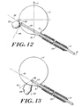
- Figure 12 illustrates treatment of a tumor 320 that is even closer to the junction of the urethra and the bladder than is tumor 315 shown in Figure 11 .
- Treatment of tumor 320 is accomplished by aligning axis 30 of guidance tube 12 with tumor 320 as described above.
- the connection between balloon 12 and tube 14 will permit alignments such that the angle between balloon axis 13 and guidance tube axis 30 is adjustable between zero and 90 degrees.
- x-ray probe 114 is inserted into tube 14 until probe tip 146 almost contacts the surface of balloon 12 adjacent to tumor 320. Again probe tip 146 is appropriately masked such that x-rays emitted from target 146 are confined within boundaries indicated by lines 148 and 150.
- Figure 13 shows treatment of a tumor 330 that is even closer to the intersection of the urethra and the bladder than is tumor 320 shown in Figure 12 .
- Tumor 330 is so close to the intersection of the urethra and the bladder that it is not possible to align axis 30 with tumor 330.
- treatment is accomplished by placing probe tip 146 as close as possible to tumor 330.
- One method of positioning the probe tip at the optimal treatment location is to use the endoscope to locate the tumor and measure the distance that the endoscope has been inserted into the balloon when the tip of the endoscope is as close as possible to the tumor. Then the x-ray probe tip can subsequently be placed at the same position since the probe is of known length.
- probe tip 146 is selected such that x-rays generated therefrom are confined within boundaries indicated by lines 148 and 150 and tumor 330 is radiated while exposing only a minimal amount of healthy tissue to x-rays.
- the treatment time of tumor 330 will be longer to compensate for the distance between target 146 and tumor 330 due to the 1/R 2 decrease in radiation intensity with distance.
- the treatment time may remain constant if the power delivered by the x-ray probe is correspondingly increased.
- the invention may be embodied in other specific forms without departing from the essential characteristics thereof.
- the invention has been described in terms of use with a spherical balloon for treatment of the bladder.
- balloons with other shapes are useful for treatment of other body cavities, e.g., a cylindrical balloon may be useful in conjunction with treatment of the colon.
Abstract
Description
- This application claims the benefit of
U.S. Patent Application Serial No. 60/004,921 , entitled Improved Apparatus for Applying X-rays to an Interior Surface of a Body Cavity, filed October 6, 1995. - The present invention relates to a miniaturized, low power, programmable x-ray source for use in delivering specifically contoured doses of x-rays to a specified region. More specifically, the invention relates to apparatus and methods for delivering desired x-ray flux to interior surfaces of body cavities.
- X-radiation applied to the soft tissue lining body cavities is known to be useful in the treatment of certain cancers, including cancer of the bladder, vagina and cervix, urethra, uterus, colon and rectum. In an ideal treatment for many conditions, only the surface of the body cavity, i.e., the target tissue, is exposed to the radiation. However, most conventional, radiation therapy utilizes an external radiation source which directs relatively high energy, and thus tissue-damaging, x-rays toward the patient, so that the x-rays must first penetrate the skin and other tissue of the patient, prior to reaching the tissue lining the body cavity. Undesirable radiation of non-target tissue is thus an unavoidable consequence of having a conventional x-ray source located outside the patient's body. Further, the use of relatively high energy, and thus tissue damaging, x-rays are required to insure that a sufficient dose is delivered to the target tissue.
- Conventional methods of radiation treatment for tissue lining body cavities also fail to provide the ability to deliver a specific dose of radiation to the target tissue, which may have an arbitrary contour. In some cases, it is desirable to provide a substantially uniform dose of radiation over a relatively large target area. In other cases, specifically contoured nonuniform doses may be desired. As used herein, the term "isodose contour" refers to a surface over which the x-ray flux density is substantially constant. In the context of an interior surface, or lining of a body cavity, a uniform dose implies generating an x-ray distribution having an isodose contour that is coincident with the interior surface of the cavity.
- Some of these disadvantages of the prior art approaches can be overcome through the use of a miniaturized low power x-ray source, such as the one described in the above-referenced
U.S. Patent No. 5,153,900 granted to Nomikos et al. That x-ray source includes an elongated tube extending along a source axis, and has an electron beam generator at one end which generates and directs an election beam along the source axis to the other end and in here it is incident upon a target which is reprone to the beam to generate x-radiation. - That source can be inserted into a patient's body, and immediately adjacent to a tissue to be treated, and then activated to generate x-rays from within, permitting generation of x-rays from points local to the target tissue. When such an x-ray source is used to treat the tissue lining a body cavity, the x-rays need not pass through the patient's bone mass, and skin, and other tissue prior to reaching the target tissue.
- One useful apparatus for delivering radiation to the interior surface of a body cavity uses a combination of a miniaturized low power x-ray source of the type disclosed in
U.S. Patent No. 5,530,900 , and an inflatable balloon. The above-referencedU.S. Patent Application Serial No. 08/273,645 , entitled X-ray Apparatus for Applying a Predetermined Flux to an Interior Surface of a Body Cavity, describes one such combination. This apparatus uses a guidance (or balloon) tube with a balloon affixed to its distal tip, where the balloon stretches the body cavity to a desired known shape, such as a sphere. The x-ray source is advanced through the balloon-tube so that its x-ray generating distal tip is positioned at a predetermined location, for example, the center, within the inflated balloon, and then is activated. In cases where it is desired to apply a uniform dose to the lining of a body cavity having a flexible defining boundary (such as the bladder), a substantially spherical (when inflated) balloon is positioned in the cavity and inflated, thereby forcing a spherical shape to the defining boundary, and thus the lining. Then a substantially omni-directional x-ray source is positioned at the center of the inflated balloon. With such a configuration, x-rays generated from within the inflated balloon establish a substantially uniform dose at the surface of the body cavity. - One important aspect of that approach is the ability to locate the x-ray source at a predetermined location within the body cavity. Inflating the balloon can stretch the body cavity to a known shape, but internal pressures near the cavity can cause the balloon-cavity structure to shift in position relative to the balloon tubes, thereby causing a misalignment between the balloon axis and the axis of the x-ray source. If the x-ray source can not be positioned accurately, it then becomes difficult to deliver a uniform dose to the surface of the body cavity.
- Another combination of an x-ray probe and a balloon is described in
U.S. Patent Application Serial No. 08/273,963 , entitled Improved X-ray Apparatus for Applying a Predetermined Flux to an Interior Surface of a Body Cavity. In this combination, opposite ends of a balloon are permanently affixed to and disposed about an extension of a balloon-tube, which passes along a diameter of the balloon when inflated. In operation with this configuration, the balloon-tube and deflated balloon are inserted into the body such that the deflated balloon is initially positioned within the cavity and the balloon is then inflated. The balloon-tube and its extension maintain alignment between the balloon-tube and the balloon. The x-ray probe is then inserted into the balloon-tube and positioned with its x-ray generating distal tip at a predetermined location along a diameter of the balloon so that x-rays can be generated from a known location within the body cavity. - One problem the with latter configuration is that the deflated balloon, when packed around the balloon-tube, forms a structure that is relatively large in diameter making insertion into and retraction from body passageways difficult. This is an important factor for relatively small passageways, such as the urethra, into which the structure is inserted for x-ray treatment of the bladder. Further, in such configurations, the balloon-tube is typically only partially transmissive of x-rays and interferes with the ability to deliver a specifically contoured dose to the target tissue.
- Also, with the above described configurations, the radiating tip of the probe can not be placed close to a cavity wall in a manner permitting radiation of local lesion on that wall.
- It is therefore an object of the invention to provide an improved method and apparatus for delivering a specifically contoured dose of radiation to the tissue lining body cavities.
- It is a further object of the invention to provide an apparatus, that includes a miniature low power x-ray source and a balloon, for delivering uniform or other desired doses of radiation to the tissue that lines a body cavity.
- Other objects and advantages of the present invention will become apparent upon consideration of the appended drawings and description thereof.
-
WO95/3201 -
US-A-5,442,678 discloses an x-ray source comprising a housing, an elongated tubular probe, a target assembly, and a beam steering assembly. The housing encloses an electron beam source, and has elements for generating an electron beam along a beam path. The elongated tubular probe extends along a central axis from the housing about the beam path. The target assembly extends along the central axis and is adapted for coupling to the end of the probe distal from the housing. The target assembly includes a target element positioned along the beam path, wherein the target element is adapted to emit x-rays in a predetermined spectral range in response to incident electrons. The beam steering assembly includes a deflection element, a feedback network, and a deflection controller. The deflection element deflects the beam from a nominal axis to a selected surface region on the target element in response to a deflection control signal. The feedback network includes deflection sensing elements for sensing the deflection of the beam and elements for generating a feedback signal representative thereof. The deflection controller couples to the deflection element and to the feedback network and includes elements for generating a deflection control signal in response to the feedback signal. - The present invention is as claimed in the claims.
- When inflated, the balloon defines a predetermined surface contour disposed about an interior region extending along a balloon attachment axis, or balloon axis, which extends across a diameter of the balloon from the junction of the balloon-tube and the balloon. The balloon axis intersects the central axis of the balloon-tube near the distal end of the balloon-tube.
- In operation, the cannula may be inserted through a body passageway, e.g., the urethra, so that the distal end of the cannula is positioned near a body cavity, e.g., the bladder, and so that the proximal end of the cannula remains external to the body. The balloon-tube and balloon, when deflated, may then be inserted through the cannula so that the balloon is positioned beyond the distal end of the cannula and within a body cavity. The balloon may then be inflated and thereby stretch the body cavity to a predetermined shape. When the balloon-tube is inserted into the cannula, the central and canula axes are normally coaxial.
- Although the balloon axis and the central axis of the balloon-tube intersect, they are generally not axially aligned immediately following inflation of the balloon. While the balloon is substantially inelastic, the material forming the balloon at the attachment between the balloon and the balloon-tube somewhat flexible, permitting the orientation between the balloon axis and the balloon-tube to be easily changed. The angle between the central and balloon axes may be adjusted by rotating the cannula about the point of intersection of the balloon and central axes, thereby permitting adjustment of the central and cannula axes into a desired angular alignment. The assembly of an aspect of the invention further includes an alignment mechanism that is operative from the proximal end of the cannula for selectively adjusting the angle between the balloon and cannula axes to a predetermined angular orientation. Preferably, the angle between the balloon and cannula axes is adjustable between zero and 90 degrees.
- The alignment mechanism may include a reference mark, or region, which is detectable (e.g., optically detectable) from the interior of the balloon. The reference mark may be located at the intersection of the balloon and the balloon axis opposite the intersection of the balloon and central axes, and the reference mark may be located on the exterior of the balloon in the case of a transparent or translucent balloon, or on the interior of the balloon. The position of the reference mark relative to the cannula axis is determinable from within the interior region of the balloon, so that a user can observe the position of the mark relative to the cannula axis, and thus know the angular orientation of the balloon axis relative to the cannula axis.
- In one form the reference mark may fluoresce in response to incident light in a predetermined spectral range. For that form, light in that spectral range may be directed via a filter to the balloon interior. An operator may manipulate the cannula axis relative to the balloon axis of the inflated balloon while monitoring the balloon interior via an output filter at a wavelength associated with the fluorescence, to detect fluorescent light from the reference mark and determine when the cannula axis is aligned with the balloon axis.
- The assembly may also include an inflation assembly disposed near the proximal end of the balloon-tube for controlling the pressure in the interior region of the balloon. The inflation assembly may provide a gas flow path extending between a pressure source and the interior channel.
- The balloon when inflated may be spherical. However, the use of balloons having cylindrical, or other shape that may be desired for a particular cavity-to-be-illuminated. Symmetry, or no symmetry at all is also used for various forms of the invention.
- The foregoing and other objects of this invention, the various features thereof, as well as the invention itself, may be more fully understood from the following description, when read together with the accompanying drawings in which:
-
Figure 1 is a cross sectional view of an apparatus according to the invention useful for providing radiation treatment to the interior surface of a body cavity, including a balloon-tube and an inflated balloon; -
Figure 2 is a view of the apparatus shown inFigure 1 in which the balloon is deflated; -
Figure 3 is a perspective view of a miniature x-ray probe according to the invention; -
Figure 4 is a cross sectional view of a kit according to the invention containing a miniature x-ray probe, a balloon-tube, a balloon, and a guidance cannula; -
Figures 5A and 5B are side and end views, respectively, of the kit, without the x-ray probe, shown inFigure 4 further including a supporting V-guide; -
Figure 6 is a side view of the kit shown inFigures 5A and 5B , showing the balloon-tube inserted within the cannula; -
Figure 7 shows an apparatus according to the invention in which the balloon is inflated within a body cavity and an endoscope has been inserted through the balloon-tube and into the balloon; -
Figures 8A and 8B are side and end views, respectively, of the kit shown inFigure 7 further showing a support frame for supporting the V-guide and providing the spatial motions for aligning the cannula with the axis of the balloon-tube; -
Figure 9 shows the apparatus ofFigure 8 in which the balloon attachment axis and the balloon-tube axis have been aligned with each other via use of an endoscope and subsequently an x-ray probe has been inserted within the balloon; -
Figure 10 shows an apparatus according to the invention useful for treating localized tumors in the bladder; -
Figure 11 shows the apparatus shown inFigure 10 being used to treat a localized tumor that is not directly opposite the distal end of the guidance tube; -
Figure 12 shows the apparatus shown inFigure 10 being used to treat a localized tumor that is relatively close to the intersection of the urethra and the bladder; -
Figure 13 shows the apparatus shown inFigure 10 being used to treat a localized tumor that is even closer to the intersection of the urethra and the bladder than the tumor shown inFigure 12 . - Like numbered elements in each FIGURE represent the same or similar elements.
-
Figures 1 and 2 show anapparatus 10 according to the present invention which is useful for providing radiation treatment to the tissue lining of a body cavity.Apparatus 10 includes a balloon-tube 14 having adistal end 16 and aproximal end 20, and includes an inelastic,spherical balloon 12 attached todistal end 16. Balloon-tube 14 is hollow and defines aninterior channel 22 extending along and about a balloon-tube axis 30.Interior channel 22 is connected with an interior region ofballoon 12 such that inflation and deflation ofballoon 12 is controllable from theproximal end 20 of balloon-tube 14.Figure 1 showsballoon 12 inflated andFigure 2 showsballoon 12 deflated, with theballoon 12 being collapsed around anaxis 13 extending coaxially fromaxis 30. - When inflated,
balloon 12 defines aballoon diameter 13, a proximal end of which is located at the center of thedistal end 16 of the balloon-tube 14 and a distal end of which is at the oppoite side of the balloon.Balloon diameter 13 will be referred to herein below as the balloon-attachment axis, or more simply as the balloon-axis. Generally, immediately after inflation, the diameter (or balloon axis) 13 is not aligned with the control axis of the balloon-tube 14. - Preferably,
balloon 12 contains a reference, or fiducial, region or mark 18 at the distal end ofballoon axis 13. Themark 18 is observable from the interior of the inflated balloon for facilitating alignment of balloon-tube axis 30 and theinflated balloon axis 13, as will be discussed further below. Thus,reference mark 18 is preferably located whereaxis 13 intersects the surface ofballoon 12 as shown inFigure 1 . In alternative embodiments,reference region 18 may include a plurality of marks disposed in a circularly symmetric pattern centered on the distal end ofaxis 13 andballoon 12. Themark 18 may be located either inside oroutside balloon 12. - In use,
balloon 12 contacts the tissue lining a body cavity and therefore is preferably composed of a biocompatable material. In the illustrated embodiment,balloon 12 is an inelastic balloon, meaning that inflation will expandballoon 12 to a predetermined shape and further inflation will not further alter the balloon's shape but will only increase interior pressure, and accordingly, the rigidity of the balloon.Balloon 12 is also preferably transparent, so body surfaces and any external reference mark can be viewed from the interior of the inflated balloon. - The balloon-
tube 14 is sized to permit insertion into a cannula which in turn is sized to facilitate insertion into body passageways such as the urethra, and the balloon is preferably chosen so that when deflated, as shown inFigure 2 , theballoon 12 can be packed into a region having a diameter no larger than that of the inner diameter of the cannula, or more preferably no larger than the outer diameter of the balloon-tube 14. - The apparatus of the present invention may also include an electron-beam (e-beam) activated x-ray source. That source may operate at relative low energy as in the range of approximately 10 kV to 90 kV, and relatively small electron beam currents, as in the range of approximately 1 nA to 1 mA. Such a source is described more completely in the above-referenced
U.S. Patent No. 5,153,900 granted to Nomikos et al. -
Figure 3 shows such anx-ray source 110 which includes an elongatedcylindrical probe 114 extending along areference axis 116 from ahousing 112 and having atarget assembly 126 at its distal end. Thehousing 112 encloses apower supply 112A. Theprobe 114 is a hollow tube having at its proximal end an electron beam generator (cathode) 122 and an associated highvoltage power supply 112A.Cathode 122 is located in close proximity to an annular focusingelectrode 123 typically at nearly the same potential as thecathode 122. The hollow,tubular probe 114, the cathode, grid, and the hole in the anode all extend along anaxis 116. An associated controller controls the greater of these elements to generate an e-beam, and direct that beam alongaxis 116 to thetarget assembly 126. The target assembly, in response to this incident e-beam, generates x-rays. In various embodiments, parts of theprobe 114 are preferably selectively shielded to control the spatial distribution of x-rays. In addition, theprobe 114 is preferably magnetically shielded to prevent external magnetic fields from deflecting the beam away from the target. -
Figure 4 shows akit 210 according to the invention for delivering x-rays to the tissue lining a body cavity.Kit 210 includesballoon 12, balloon-tube 14, and x-ray probe 114 (housing 112 is not shown).Kit 210 further includes an elongatedtubular cannula 214.Cannula 214 defines anaxis 230 and has an inner diameter slightly larger than the outer diameter of balloon-tube 14, such that balloon-tube 14 andballoon 12 when deflated are slidably positionable within aninterior channel 222 ofcannula 214 so that balloon-tube axis 30 is substantially coaxial withcannula axis 230. Preferably, the walls ofcannula 214 includes interior channels which permit flow therethrough of a fluid coolant. Preferably, the walls ofcannula 214 also include channels permitting flow of urine from the bladder, as well as the flow of gas into the bladder (so that the bladder can be inflated to facilitate inflation of the balloon 12). - A
proximal end 220 ofcannula 214 is integrally mounted to a cooled-cannula water andurine manifold 223 which is supported by a docking clamp (or block) 224 useful for aligningcannula 214 as will be discussed further below.Manifold 223 also allows gas (preferably (CO2) to be introduced through the urine channel in order to inflate the bladder. Balloon inflation is accomplished by means ofgas inlet 64 as described below. - In a preferred embodiment the
cannula 214 is constructed from surgical steel or other biocompatable material. In use, thecannula 214 is inserted into body passageways, such as the urethra, or surgically made passageways. Sincecannula 214 is relatively rigid, balloon-tube 14 may be relatively flexible and may be fabricated from, for example, light weight, thin, plastic. -
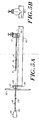
Figure 4 showsproximal end 20 of balloon-tube 14 integrally mounted in a pressure-lock module 50, which provides for the introduction of gas pressure into the balloon and subsequent introduction of an endoscope or the x-ray probe into the balloon without losing pressure in the balloon. Pressure-lock module 50 defines aninterior channel 52 extending fromproximal end 20 of balloon-tube 14 to anend 60 of pressure-lock module 50 such thatinterior channel 52 is connected to and coaxial withinterior channel 22 of balloon-tube 14 (shown inFigure 1 ).Interior channel 52 is sized such thatx-ray probe 114 is slidably positionable withinchannel 52. - The balloon-
tube 14 is affixed to pressure-lock module 50 by way of aclamp 233.Figure 4 shows balloon-tube 14 inserted withincannula 214 such that thedistal end 16 of balloon-tube 14 extends beyond adistal end 216 ofcannula 214. In this position,balloon 12 is free to expand without being constricted bycannula 214.Figure 4 further showsx-ray probe 114 inserted within balloon-tube 14 such thatx-ray target 126 is centered within inflatedspherical balloon 12. - Pressure-
lock module 50 includes a sealing O-ring 62 for forming an air-tight seal withprobe 114 for preventing pressurized gas from escapinginflated balloon 12 whenprobe 114 is inserted withinchannel 52. O-ring 62 is preferably made of rubber or other resilient material suitable for forming air-tight seals. In addition to O-ring 62, pressure-lock module 50 may include other o-rings distributed in a conventional fashion throughmodule 50 to assist in forming a gas-tight seal withprobe 114. - Pressure-
lock module 50 further provides apressure port 64 which may be coupled to a tank of pressurized gas or a pump (not shown) for controlling inflation and deflation ofballoon 12. Pressure-lock module 50 further providesgate valve 66 and O-rings 68 for sealingchannel 52 and thereby maintaining pressure withinballoon 12 when the x-ray probe or an endoscope are not present in o-ring 62.Gate valve 66, which is shown in an open position inFigure 4 , is slidably mounted within pressure-lock module 50. In its open position,gate valve 66 does not obstructchannel 52 and allowsprobe 114 to be inserted into balloon-tube 14. Whenprobe 114 is withdrawn,gate valve 66 can slide downwards such that O-rings 68 andgate valve 66 form a gas-tight seal preventing gas from flowing between the interior ofballoon 12 and end 60 of pressure-lock module 50. -
Pressure lock module 50 thus provides several methods for controlling the inflation and deflation ofballoon 12 while introducing either the probe or endoscope into the balloon. For example, ifballoon 12 is initially deflated,gate valve 66 may be moved downwards to its closed position and a gas pump (not shown) can pump gas throughpressure port 64 intoballoon 12 until the balloon is inflated to a desired pressure.Gate valve 66 and O-rings 68 prevent any gas from escaping throughend 60. Onceprobe 114, or other such instrument, is inserted intochannel 52 such thattarget end 126 is beyond O-ring 62,gate valve 66 can be retracted to its open position as shown inFigure 4 . The seal formed by O-ring 62 and probe 114 will prevent any gas from escaping the balloon. Probe 114 can then be inserted such thattarget 126 is positioned at a desired location withininflated balloon 12 as shown inFigure 4 . This final insertion ofprobe 114 increases the pressure insideballoon 12 slightly becauseprobe 114 drives some of the gas that was insidechannel 22 intoballoon 12. This slight increase in pressure is generally negligible and does not interfere with the operation ofkit 210. However in some situations, it is desirable to connect a pressure control valve (not shown) toport 64 to maintain constant pressure withinballoon 12 asprobe 114 is being inserted. - The operation of
kit 210 will now be discussed in connection with providing an exemplary radiation treatment to a bladder. As those skilled in the art will appreciate, radiation treatment of other body cavities can be accomplished in a similar manner. Referring toFigures 5A and 5B , initially cannula 214 is inserted into the urethra of a patient such thatdistal end 216 is positioned near the intersection of a urethra and abladder 300.Proximal end 220 ofcannula 214 remains outside the body of the patient. The body wall of the patient is shown schematically at 302 inFigure 5A . As is further shown inFigure 5A , thebladder 300 initially has an irregular shape. - In the preferred embodiment,
kit 210 includes a V-guide 410 used for alignment as will be discussed further below. V-guide 410 provides a surface bearing a V-shapedgroove 412 extending along anaxis 430.Docking clamp 224 may be fixed to one end of V-guide 410, andmanifold 223 may be clamped todocking clamp 224. When manifold 223 is clamped todocking clamp 224, thecannula axis 230 ofcannula 214 is parallel toaxis 430 of V-guide 410. - Once
cannula 214 is inserted into the patient so that thedistal end 216 is positioned near the intersection of the urethra and the bladder, V-guide 410 andcannula 214 are aligned by clampingmanifold 223 todocking clamp 224. Next, pressure-lock module 50 is positioned on V-shapedgroove 412 as shown inFigure 5A . When pressure-lock module 50 is positioned ongroove 412, the balloon-tube axis 30 of balloon-tube 14 is substantially coaxial withcannula axis 230. Initially,balloon 12 is deflated and is packed so that it extends alongcentral axis 30 and so that the outer diameter ofballoon 12 does not exceed the outer diameter of balloon-tube 14. Pressure-lock module 50 is then advanced alonggroove 412 towardsdocking clamp 224 so that deflatedballoon 12 and balloon-tube 14 are inserted throughcannula 214. Preferably, the components are sized so that when pressure-lock module.50 abutsdocking clamp 224, thedistal end 16 of balloon-tube 14 extends just beyond thedistal end 216 ofcannula 214 so thatballoon 12 extends into thebladder 300. -
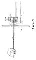
Figure 6 shows pressure-lock module 50 abuttingdocking clamp 224 andballoon 12 inflated so thatballoon 12 has stretchedbladder 300 to a uniform spherical shape. In many cases it is desirable to inflate bladder 300 (via gas flow in the urine channels of cannula 214) prior to inflation ofballoon 12 so that minimal stress is applied to the bladder during inflation of the balloon. As is shown inFigure 6 , afterballoon 12 is inflated, internal pressures from the patient's body typically causeballoon 12 to shift relative to cannula 214 so thatballoon axis 13 is angularly offset with respect to cannula/balloon-tube axes balloon 12 is inelastic or non-stretchable, the junction betweenballoon 12 andguidance tube 14 is flexible. As a consequence of such a misalignment ofaxes x-ray probe 114 throughguidance tube 14 so that itstip 126 is positioned at the center ofballoon 12. -
Figure 7 shows anendoscope 500 inserted into theballoon 12. The misalignment ofaxes guide 410 concurrently withcannula 214 and balloon-tube 14 aboutdistal end 16 of the balloon-tube (which has been previously located near the neck of the bladder, i.e., the intersection of the urethra and the bladder, which is the most anatomically desirable point of rotation for the tubes). The alignment ofaxes fiducial mark 18. - As is well known in the art, endoscopes are normally constructed from optical fibers or lenses held in alignment by an elongated cylindrical casing. The outer diameter of
endoscope 500 is preferably chosen to be similar to that ofX-ray probe 114 so thatendoscope 500 forms a gas-tight seal with pressure-lock module 50. Insertion ofendoscope 500 into balloon-tube 14 therefore does not cause loss of pressure fromballoon 12.Endoscope 500 is shown fixed to acylindrical endoscope holder 502 which is sized so that whenholder 502 rests on V-groove 412 the axis ofendoscope 500 is coaxial with theaxis 30 of balloon-tube 14 (shown inFigure 4 ) so thatendoscope 500 may be inserted into balloon-tube 14 simply by advancingholder 502 along V-groove 412 towardspressure lock module 50. ACCD camera 504 is attached toholder 502 to provide a display of the interior ofballoon 12 as viewed byendoscope 500. The optics ofendoscope 500 preferably contain cross-hairs which are aligned with the central axis of theendoscope 500. Alignment ofballoon axis 13 and balloon-tube axis 30 may be achieved by aligning the cross-hairs ofendoscope 500 withfiducial mark 18. - Once alignment of
axes guide 410 is preferably locked into the proper position to preserve the alignment.Kit 210 preferably includes a multi-axis support system for supporting V-guide 410 (as shown inFigures 8A-B). Figures 8A and 8B show front and side views, respectively, of amulti-axis support system 600. Preferably,support system 600 provides at least five degrees of freedom (x, y, z, θ (polar angle) and φ (azimuth angle)) so that it can conveniently support V-guide 410 at any arbitrary angle while keeping the distal end of the balloon-tube fixed in space.Figure 8A shows pressure-lock module 50 andendoscope holder 502 resting on V-guide 410, andsupport system 600 supporting V-guide 410. V-guide 410 is positioned so thataxes guide 410 andsupport system 600 are preferably fixed, or locked, so that a surgeon may removeendoscope 500 and subsequently insertx-ray probe 114 without fear of disturbing the alignment. - Withdrawal of
endoscope 500 and insertion ofprobe 114 are accomplished without loss of pressure fromballoon 12 by use of gate valve 66 (since loss of pressure from, and reinflation of,balloon 12 may disturb the alignment). Withdrawal ofendoscope 500 is accomplished by retractingholder 502 so that the distal tip ofendoscope 500 is retracted just beyondgate valve 66 and such that it is still forward of O-ring 62 so thatendoscope 500 still maintains a gas-tight seal with pressure-lock module 50.Gate valve 66 is then moved to its closed position (as shown inFigure 6 ) andendoscope 500 is completely withdrawn from pressure-lock module 50.Probe 114 is then inserted into pressure-lock module 50 so thattarget 126 is forward of O-ring 68 so thatprobe 114 forms a gas-tight seal with pressure-lock module 50.Gate valve 66 is then moved to its open position and probe 114 is inserted intoballoon 12. -
Figure 9 showsprobe 114 inserted so thattarget 126 is centered withininflated balloon 12.Housing 112 ofprobe 114 is configured so that whenhousing 112 rests on V-groove 412,probe 114 is aligned withaxis 30 of balloon-tube 14 so thatprobe 114 may be inserted into balloon-tube 14 simply by advancinghousing 112 along V-groove 412 towards pressure-lock module 50. Further,housing 112 and probe 114 are preferably sized so that whenhousing 112 abuts pressure-lock module 50,target 126 is centered withininflated balloon 12. - Once
target 126 is centered withinballoon 12,x-ray source 110 is operated to direct an e-beam to be inadent ontarget 126, which in turn generates x-rays. Sincetarget 126 acts as a nominal point source, it generates an x-ray field having spherical isodose contours. Therefore, a uniform dose of x-rays is delivered to the tissue lining thebladder 300. - After treatment,
probe 114 is removed, and then balloon 12 is deflated as described above.Deflated balloon 12,guidance tube 14 andcannula 214 are then withdrawn from the body. - Accordingly,
kit 210 allows delivery of a uniform dose of x-rays to the tissue lining a body cavity. Since the x-rays are generated from within the cavity, the x-rays need not first penetrate the patient's bone mass or skin, and other tissue prior to reaching the target site. Thus,kit 210 allows delivery of a uniform dose of x-rays to the target tissue substantially without radiating non-targeted tissue. Further, since the x-rays need not first penetrate non-target tissue prior to reaching the target site, relatively low energy x-rays can be used, compared to the prior art. - In addition to providing a uniform dose of radiation to tissue lining a body cavity as has been described above, apparatus according to the invention may also be used to provide a specifically contoured dose useful for treating a tumor or other local lesion.
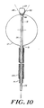
Figure 10 shows an apparatus for treating atumor 310. In this embodiment, the normal probe tip ofx-ray probe 114 which generally acts as a point, or omnidirectional, source of x-rays is replaced with aprobe tip 146 which generates an x-ray field having a specific controlled spatial distribution.Probe tip 146 is generally fabricated by covering the normal probe tip with a variable thickness x-ray shield, or a shadow mask as it is sometimes called in the art. The structure of such x-ray shields is more fully discussed in the above-referencedU.S. Patent Application Serial No. 08/184,271 , entitled X-ray Source with Shaped Radiation Pattern. -
Probe tip 146 is preferably positioned so that it almost touchesballoon 12 adjacent totumor 310, and probe 114 is then operated to generate x-rays. As shown inFigure 10 ,probe tip 146 generates an x-ray field contained within the boundaries shown bylines tumor 310 is effectively radiated while only a minimal amount of healthy tissue is exposed to radiation. - The above-described methods of aligning
tube 14 andballoon 12 are also useful in treatingtumor 310. For example, after inflation ofballoon 12, an endoscope may be inserted to locatetumor 310. Once alignment has been achieved betweenaxis 30 of balloon-tube 14 andtumor 310, the endoscope is withdrawn and probe 114 is inserted untiltarget 146 almost makes contact with the interior surface ofballoon 12. -
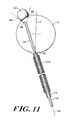
Figure 10 shows treatment of atumor 310 that is directly opposite thedistal end 16 of balloon-tube 14. As shown inFigures 11-13 , the same apparatus is useful for treating tumors which are located in different regions of the bladder. Thetumor 315 shown inFigure 11 is also on the dome of the bladder but displaced from the apex. Therefore, to positionprobe tip 146adjacent tumor 315,tube 14 is aligned such that balloon-tube axis 30 is not coaxial withballoon axis 13. Alignment may be accomplished as described above by using an endoscope to align balloon-tube axis 30 withtumor 315.Axes balloon 12 as shown inFigure 11 . Since the balloon material is essentially inelastic there will be no stretching of the balloon to accommodate the misalignment ofaxes x-ray probe 114 is inserted intotube 14 untiltarget 146 almost contacts the surface ofballoon 12 adjacent totumor 315. Again probetip 146 is appropriately masked such that x-rays emitted fromtarget 146 are confined within boundaries indicated bylines -
Figure 12 illustrates treatment of atumor 320 that is even closer to the junction of the urethra and the bladder than istumor 315 shown inFigure 11 . Treatment oftumor 320 is accomplished by aligningaxis 30 ofguidance tube 12 withtumor 320 as described above. In the preferred embodiment, the connection betweenballoon 12 andtube 14 will permit alignments such that the angle betweenballoon axis 13 andguidance tube axis 30 is adjustable between zero and 90 degrees. After alignment,x-ray probe 114 is inserted intotube 14 untilprobe tip 146 almost contacts the surface ofballoon 12 adjacent totumor 320. Again probetip 146 is appropriately masked such that x-rays emitted fromtarget 146 are confined within boundaries indicated bylines -
Figure 13 shows treatment of atumor 330 that is even closer to the intersection of the urethra and the bladder than istumor 320 shown inFigure 12 .Tumor 330 is so close to the intersection of the urethra and the bladder that it is not possible to alignaxis 30 withtumor 330. In this case treatment is accomplished by placingprobe tip 146 as close as possible totumor 330. One method of positioning the probe tip at the optimal treatment location is to use the endoscope to locate the tumor and measure the distance that the endoscope has been inserted into the balloon when the tip of the endoscope is as close as possible to the tumor. Then the x-ray probe tip can subsequently be placed at the same position since the probe is of known length. Again,probe tip 146 is selected such that x-rays generated therefrom are confined within boundaries indicated bylines tumor 330 is radiated while exposing only a minimal amount of healthy tissue to x-rays. As those skilled in the art will appreciate, the treatment time oftumor 330 will be longer to compensate for the distance betweentarget 146 andtumor 330 due to the 1/R2 decrease in radiation intensity with distance. Alternatively, the treatment time may remain constant if the power delivered by the x-ray probe is correspondingly increased. - The invention may be embodied in other specific forms without departing from the essential characteristics thereof. For example, the invention has been described in terms of use with a spherical balloon for treatment of the bladder. As those skilled in the art will appreciate, balloons with other shapes are useful for treatment of other body cavities, e.g., a cylindrical balloon may be useful in conjunction with treatment of the colon.
- The present embodiments are therefore to be considered in all respects as illustrative and not restrictive, the scope of the invention being indicated by the appended claims rather than by the foregoing description.
Claims (14)
- A kit for applying X-rays to an interior surface of a body cavity; said kit comprising:A) an x-ray source guidance assembly, said assembly including a guidance cannula (214) extending along a cannula axis end having a proximal end and a distal end, said guidance cannula (214) defining an interior channel (222) extending along said cannula axisB) a balloon-tube (14) extending along a central axis (30) and having a proximal end (20) and a distal end (16), said tube (14) defining an interior channel extending along said central axis (30), said balloon-tube (14) being insertable within said interior channel (222) of said guidance cannula (214);C) an inflatable balloon (12) affixed to and extending from said tube (14) at points near said distal end (16) of said tube (14), said balloon (12) when inflated defining a predetermined surface contour disposed about an interior region extending along a balloon axis (13), said interior channel and interior region of said balloon (12) being contiguous, and said balloon axis (13) intersecting said central axis (30) near said distal end (16) of said tube (14), andD) an x-ray source cooperative with said tube (14), said x-ray source including an x-ray generator disposed at or near a target end of an elongated tubular element wherein said tubular element is slidably positionable within said interior channel such that said target end is positionable within said balloon (12) when inflated
characterised in that the inflatable balloon is inelastic and that the fit further comprisesE) alignment means operative from said proximal end (20) of said tube (14), for selectively aligning said balloon axis (13) and said central axis (30) to a predetermined angular orientation; - A kit according to claim 1, wherein said angular orientation is adjustable between zero degrees and at least 90 degrees.
- A kit according to claim 1, wherein said alignment means comprises a reference region on said balloon (12), the position of said reference region relative to said central axis (30) being determinable from within said interior region, and, optionally,
wherein said reference region is in the interior region of said balloon (12) and wherein said reference region fluoresces in response to incident light in a predetermined spectral range, and, further optionally,
further including means for irradiating said reference region with light in said predetermined spectral range and including means for detecting fluorescent light generated by said reference region. - A kit according to claim 1, further including inflation means for controlling a pressure in said balloon interior region, said inflation means disposed near said proximal end, and, optionally,
wherein said inflation means includes a gas flow path extending between said interior channel and a pressure source. - A kit according to claim 1, wherein said balloon (12) when inflated is symmetrically disposed about said balloon axis.
- A kit according to claim 1, wherein said predetermined surface contour is spherical or cylindrical.
- A kit according to claim 1, wherein said tube (14) includes an interior wall and an exterior wall wherein said interior wall defines one boundary of said interior channel, wherein said guidance tube includes a cooling channel between said interior wall and said exterior wall extending from a fluid inlet in said exterior wall to a fluid outlet in said exterior wall, and, optionally,
wherein said fluid inlet and said fluid outlet are near said proximal end (20), and further optionally,
wherein said cooling channel extends to a point near said distal end. - A kit according to claim 1, said balloon (12) when deflated being collapsible into a volume extending along an axis substantially parallel to said central axis (30).
- A kit according to claim 1, wherein said tube (14) is characterized by an outer diameter, said balloon (12) when deflated being collapsible into a volume having an outer diameter less than or equal to said outer diameter of said tube (14).
- A kit according to claim 5, wherein said target end is positionable at a center of said balloon (12).
- A kit according to claim 1, wherein said x-ray generator is an omnidirectional generator.
- A kit according to claim 1, wherein said target end includes a shield means for controlling a spatial distribution of isodose contours of said x-rays emitted by said x-ray generator, and, optionally,
wherein said shield means includes a shield cover characterized by a selected x-ray transmission profile, wherein said shield cover is disposed adjacent to said x-ray generator. - A kit according to claim 1, wherein said distal end of said cannula is positionable inside the body near the body cavity, and wherein said tube (14) and said balloon (12) when deflated are slidably positionable within said cannula, and, optionally,
further including alignment means, wherein said alignment means includes a guide extending along a guide axis and means for clamping said cannula such that said guide axis is parallel to said central axis (30) of said cannula when said alignment means is clamped to said proximal end of said cannula, in which case, further optionally,
wherein said proximal end of said cannula is slidably mountable on said guide such that said cannula is slidably positionable within said cannula when said proximal end of said cannula is mounted on said guide, in which case, yet further optionally,
wherein a proximal end of said x-ray source is slidably mountable on said guide such that said target end is slidably positionable within said cannula when said proximal end of said xray source is mounted on said guide. - A kit according to claim 1, wherein said cannula is characterized by an inner diameter, said balloon (12) when deflated being collapsible into a volume having an outer diameter less than or equal to said inner diameter of said cannula.
Applications Claiming Priority (3)
| Application Number | Priority Date | Filing Date | Title |
|---|---|---|---|
| US492195P | 1995-10-06 | 1995-10-06 | |
| US604921P | 1995-10-06 | ||
| PCT/US1996/015989 WO1997012540A1 (en) | 1995-10-06 | 1996-10-04 | Improved apparatus for applying x-rays to an interior surface of a body cavity |
Publications (3)
| Publication Number | Publication Date |
|---|---|
| EP0853461A1 EP0853461A1 (en) | 1998-07-22 |
| EP0853461A4 EP0853461A4 (en) | 2006-05-24 |
| EP0853461B1 true EP0853461B1 (en) | 2010-04-28 |
Family
ID=21713192
Family Applications (1)
| Application Number | Title | Priority Date | Filing Date |
|---|---|---|---|
| EP96938617A Expired - Lifetime EP0853461B1 (en) | 1995-10-06 | 1996-10-04 | Improved apparatus for applying x-rays to an interior surface of a body cavity |
Country Status (9)
| Country | Link |
|---|---|
| US (1) | US5748699A (en) |
| EP (1) | EP0853461B1 (en) |
| JP (1) | JP4020965B2 (en) |
| KR (1) | KR19990064070A (en) |
| CN (1) | CN1202809A (en) |
| AT (1) | ATE465670T1 (en) |
| CA (1) | CA2233960A1 (en) |
| DE (1) | DE69638174D1 (en) |
| WO (1) | WO1997012540A1 (en) |
Families Citing this family (75)
| Publication number | Priority date | Publication date | Assignee | Title |
|---|---|---|---|---|
| US6464697B1 (en) * | 1998-02-19 | 2002-10-15 | Curon Medical, Inc. | Stomach and adjoining tissue regions in the esophagus |
| EP0860181B1 (en) | 1997-02-21 | 2004-04-28 | Medtronic Ave, Inc. | X-ray device having a dilatation structure for delivering localized radiation to an interior of a body |
| US6143015A (en) * | 1997-05-19 | 2000-11-07 | Cardio Medical Solutions, Inc. | Device and method for partially occluding blood vessels using flow-through balloon |
| US6936057B1 (en) | 1997-05-19 | 2005-08-30 | Cardio Medical Solutions, Inc. (Cms) | Device and method for partially occluding blood vessels using flow-through balloon |
| WO1998052476A1 (en) * | 1997-05-19 | 1998-11-26 | Castle Professional Services, Inc. | Device for partially occluding blood vessels |
| JP4212128B2 (en) * | 1997-07-02 | 2009-01-21 | 株式会社東芝 | Radiation therapy equipment |
| DE19731307C1 (en) * | 1997-07-15 | 1998-11-12 | Ifg Inst Fuer Geraetebau Gmbh | Tissue radiation therapy apparatus |
| US5854822A (en) | 1997-07-25 | 1998-12-29 | Xrt Corp. | Miniature x-ray device having cold cathode |
| CA2307208A1 (en) * | 1997-10-15 | 1999-04-22 | Polarx Biopharmaceuticals, Inc. | Compositions and methods for the treatment of primary and metastatic neoplastic diseases using arsenic compounds |
| US6108402A (en) | 1998-01-16 | 2000-08-22 | Medtronic Ave, Inc. | Diamond vacuum housing for miniature x-ray device |
| US6496561B1 (en) * | 1998-03-06 | 2002-12-17 | Medtronic Ave, Inc. | Devices, methods and systems for delivery of X-ray |
| WO1999045563A1 (en) * | 1998-03-06 | 1999-09-10 | Xrt Corp. | Method and x-ray device using adaptable power source |
| US6036631A (en) * | 1998-03-09 | 2000-03-14 | Urologix, Inc. | Device and method for intracavitary cancer treatment |
| US6289079B1 (en) | 1999-03-23 | 2001-09-11 | Medtronic Ave, Inc. | X-ray device and deposition process for manufacture |
| US6464625B2 (en) | 1999-06-23 | 2002-10-15 | Robert A. Ganz | Therapeutic method and apparatus for debilitating or killing microorganisms within the body |
| EP1196093B1 (en) | 1999-07-02 | 2006-06-14 | Quickpass, Inc. | Suturing device |
| US6353658B1 (en) | 1999-09-08 | 2002-03-05 | The Regents Of The University Of California | Miniature x-ray source |
| AU780278B2 (en) | 1999-11-16 | 2005-03-10 | Covidien Lp | System and method of treating abnormal tissue in the human esophagus |
| US20060095032A1 (en) | 1999-11-16 | 2006-05-04 | Jerome Jackson | Methods and systems for determining physiologic characteristics for treatment of the esophagus |
| US20040215235A1 (en) | 1999-11-16 | 2004-10-28 | Barrx, Inc. | Methods and systems for determining physiologic characteristics for treatment of the esophagus |
| US6301328B1 (en) | 2000-02-11 | 2001-10-09 | Photoelectron Corporation | Apparatus for local radiation therapy |
| US6285735B1 (en) | 2000-02-11 | 2001-09-04 | Photoelectron Corporation | Apparatus for local radiation therapy |
| US7109505B1 (en) | 2000-02-11 | 2006-09-19 | Carl Zeiss Ag | Shaped biocompatible radiation shield and method for making same |
| US6421416B1 (en) * | 2000-02-11 | 2002-07-16 | Photoelectron Corporation | Apparatus for local radiation therapy |
| AUPR785001A0 (en) * | 2001-09-21 | 2001-10-18 | Kleiner, Daniel E. | Tamponade apparatus and method of using same |
| US6923754B2 (en) | 2002-11-06 | 2005-08-02 | Senorx, Inc. | Vacuum device and method for treating tissue adjacent a body cavity |
| US8328710B2 (en) | 2002-11-06 | 2012-12-11 | Senorx, Inc. | Temporary catheter for biopsy site tissue fixation |
| US7150745B2 (en) | 2004-01-09 | 2006-12-19 | Barrx Medical, Inc. | Devices and methods for treatment of luminal tissue |
| US7662082B2 (en) | 2004-11-05 | 2010-02-16 | Theragenics Corporation | Expandable brachytherapy device |
| EP1909655A2 (en) | 2005-06-20 | 2008-04-16 | Sutura, Inc. | Method and apparatus for applying a knot to a suture |
| US8273006B2 (en) | 2005-11-18 | 2012-09-25 | Senorx, Inc. | Tissue irradiation |
| US7413539B2 (en) | 2005-11-18 | 2008-08-19 | Senorx, Inc. | Treatment of a body cavity |
| US7465268B2 (en) | 2005-11-18 | 2008-12-16 | Senorx, Inc. | Methods for asymmetrical irradiation of a body cavity |
| US7997278B2 (en) | 2005-11-23 | 2011-08-16 | Barrx Medical, Inc. | Precision ablating method |
| US8702694B2 (en) * | 2005-11-23 | 2014-04-22 | Covidien Lp | Auto-aligning ablating device and method of use |
| US7959627B2 (en) | 2005-11-23 | 2011-06-14 | Barrx Medical, Inc. | Precision ablating device |
| US20070167967A1 (en) * | 2006-01-13 | 2007-07-19 | Olympus Medical Systems Corp. | Medical procedure via natural orifice and puncture device |
| US7727137B2 (en) * | 2006-10-13 | 2010-06-01 | Xoft, Inc. | Balloon brachytherapy applicator and method |
| US8287442B2 (en) | 2007-03-12 | 2012-10-16 | Senorx, Inc. | Radiation catheter with multilayered balloon |
| WO2008121738A2 (en) | 2007-03-29 | 2008-10-09 | Sutura, Inc. | Suturing devices and methods for closing a patent foramen ovale |
| US8641711B2 (en) | 2007-05-04 | 2014-02-04 | Covidien Lp | Method and apparatus for gastrointestinal tract ablation for treatment of obesity |
| US8784338B2 (en) | 2007-06-22 | 2014-07-22 | Covidien Lp | Electrical means to normalize ablational energy transmission to a luminal tissue surface of varying size |
| US8251992B2 (en) | 2007-07-06 | 2012-08-28 | Tyco Healthcare Group Lp | Method and apparatus for gastrointestinal tract ablation to achieve loss of persistent and/or recurrent excess body weight following a weight-loss operation |
| BRPI0813579A2 (en) | 2007-07-06 | 2014-12-30 | Barrx Medical Inc | Methods for treating a bleeding area in a gastrointestinal tract and ablatively treating a target site within a bleeding area of a gastrointestinal tract and ablation system. |
| US8273012B2 (en) | 2007-07-30 | 2012-09-25 | Tyco Healthcare Group, Lp | Cleaning device and methods |
| US8646460B2 (en) | 2007-07-30 | 2014-02-11 | Covidien Lp | Cleaning device and methods |
| US8360950B2 (en) | 2008-01-24 | 2013-01-29 | Senorx, Inc. | Multilumen brachytherapy balloon catheter |
| US8771296B2 (en) | 2008-05-09 | 2014-07-08 | Nobles Medical Technologies Inc. | Suturing devices and methods for suturing an anatomic valve |
| CN110074746B (en) * | 2008-10-20 | 2021-11-26 | 智能医疗系统有限公司 | Assembly for use in an endoscope and use thereof |
| US9248311B2 (en) | 2009-02-11 | 2016-02-02 | Hologic, Inc. | System and method for modifying a flexibility of a brachythereapy catheter |
| US9579524B2 (en) | 2009-02-11 | 2017-02-28 | Hologic, Inc. | Flexible multi-lumen brachytherapy device |
| KR101146917B1 (en) * | 2009-04-28 | 2012-05-22 | 한국전기연구원 | System for Brachytherapy using Nano-Emitter Based X-ray and Warm Catheter |
| US10207126B2 (en) | 2009-05-11 | 2019-02-19 | Cytyc Corporation | Lumen visualization and identification system for multi-lumen balloon catheter |
| WO2010137025A2 (en) * | 2009-05-29 | 2010-12-02 | Smart Medical Systems Ltd. | Anchoring assemblies for endoscopes |
| US9352172B2 (en) | 2010-09-30 | 2016-05-31 | Hologic, Inc. | Using a guide member to facilitate brachytherapy device swap |
| US10342992B2 (en) | 2011-01-06 | 2019-07-09 | Hologic, Inc. | Orienting a brachytherapy applicator |
| US8915833B1 (en) | 2011-02-15 | 2014-12-23 | Velayudhan Sahadevan | Image guided intraoperative simultaneous several ports microbeam radiation therapy with microfocus X-ray tubes |
| US9636525B1 (en) | 2011-02-15 | 2017-05-02 | Velayudhan Sahadevan | Method of image guided intraoperative simultaneous several ports microbeam radiation therapy with microfocus X-ray tubes |
| US10278774B2 (en) | 2011-03-18 | 2019-05-07 | Covidien Lp | Selectively expandable operative element support structure and methods of use |
| EP3644194B1 (en) | 2011-04-15 | 2022-12-07 | Heartstitch, Inc. | Suturing devices for suturing an anatomic valve |
| US20150051576A1 (en) * | 2012-03-30 | 2015-02-19 | Koninklijke Philips N.V. | Nested cannula tips |
| WO2013170081A1 (en) | 2012-05-11 | 2013-11-14 | Heartstitch, Inc. | Suturing devices and methods for suturing an anatomic structure |
| EP3016598B1 (en) | 2013-07-02 | 2018-10-10 | Med-venture Investments, LLC | Suturing devices for suturing an anatomic structure |
| JP6469109B2 (en) | 2013-12-06 | 2019-02-13 | メッド − ベンチャー インベストメンツ、エルエルシー | Suture method and apparatus |
| US10178993B2 (en) | 2014-07-11 | 2019-01-15 | Cardio Medical Solutions, Inc. | Device and method for assisting end-to-side anastomosis |
| US10687801B2 (en) | 2016-04-11 | 2020-06-23 | Nobles Medical Technologies Ii, Inc. | Suture spools for tissue suturing device |
| JP2020516907A (en) * | 2017-04-17 | 2020-06-11 | ラピスキャン・システムズ,インコーポレーテッド | X-ray tomography examination system and method |
| US11839370B2 (en) | 2017-06-19 | 2023-12-12 | Heartstitch, Inc. | Suturing devices and methods for suturing an opening in the apex of the heart |
| EP3641663B1 (en) | 2017-06-19 | 2022-03-02 | Heartstitch, Inc. | Suturing systems and methods for suturing body tissue |
| EP3668415B1 (en) | 2017-08-18 | 2023-10-25 | Nobles Medical Technologies II, Inc. | Apparatus for applying a knot to a suture |
| WO2019069432A1 (en) * | 2017-10-05 | 2019-04-11 | オリンパス株式会社 | Endoscope system and method using endoscope system |
| CN108853752B (en) * | 2018-03-22 | 2024-01-02 | 戴建荣 | Bladder illuminator and method for determining thickness of scattering foil and modulator in bladder illuminator |
| CN112402807B (en) * | 2020-11-18 | 2021-11-23 | 中国人民解放军总医院 | Photodynamic therapeutic apparatus for human body cavity and cavity organ |
| WO2022150592A1 (en) * | 2021-01-10 | 2022-07-14 | Ma Eric Hsinhua | Neutron capture therapy system and device |
| CN115417584B (en) * | 2022-09-16 | 2023-03-21 | 珠海瑞能真空电子有限公司 | Manufacturing process of CT bulb tube |
Family Cites Families (10)
| Publication number | Priority date | Publication date | Assignee | Title |
|---|---|---|---|---|
| DE3323365C2 (en) * | 1982-09-04 | 1994-10-20 | Gsf Forschungszentrum Umwelt | Method and device for illuminating cavities |
| US4838864A (en) * | 1987-11-13 | 1989-06-13 | Mansfield Scientific, Inc. | Pressure controller |
| US4981142A (en) * | 1988-06-24 | 1991-01-01 | Dachman Abraham H | Compression device |
| US5514091A (en) * | 1988-07-22 | 1996-05-07 | Yoon; Inbae | Expandable multifunctional manipulating instruments for various medical procedures |
| US5442678A (en) * | 1990-09-05 | 1995-08-15 | Photoelectron Corporation | X-ray source with improved beam steering |
| US5153900A (en) | 1990-09-05 | 1992-10-06 | Photoelectron Corporation | Miniaturized low power x-ray source |
| US5370134A (en) * | 1991-05-29 | 1994-12-06 | Orgin Medsystems, Inc. | Method and apparatus for body structure manipulation and dissection |
| CA2079974C (en) * | 1991-10-07 | 1996-07-23 | Edward J. Rhinehart | Probe for mri imaging and spectroscopy particularly in the cervical region |
| US5530900A (en) | 1994-04-20 | 1996-06-25 | Zenith Electronics Corporation | Display system for selectively displaying different types of information depending upon the detection of non-standard switch selections |
| CA2194759C (en) * | 1994-07-12 | 1999-09-14 | Donald O. Smith | X-ray apparatus for applying a predetermined flux to an interior surface of a body cavity |
-
1996
- 1996-10-04 WO PCT/US1996/015989 patent/WO1997012540A1/en not_active Application Discontinuation
- 1996-10-04 EP EP96938617A patent/EP0853461B1/en not_active Expired - Lifetime
- 1996-10-04 US US08/725,732 patent/US5748699A/en not_active Expired - Lifetime
- 1996-10-04 AT AT96938617T patent/ATE465670T1/en not_active IP Right Cessation
- 1996-10-04 DE DE69638174T patent/DE69638174D1/en not_active Expired - Lifetime
- 1996-10-04 CA CA002233960A patent/CA2233960A1/en not_active Abandoned
- 1996-10-04 CN CN96198516A patent/CN1202809A/en active Pending
- 1996-10-04 JP JP51448997A patent/JP4020965B2/en not_active Expired - Lifetime
- 1996-10-04 KR KR1019980702549A patent/KR19990064070A/en not_active Application Discontinuation
Also Published As
| Publication number | Publication date |
|---|---|
| US5748699A (en) | 1998-05-05 |
| EP0853461A4 (en) | 2006-05-24 |
| EP0853461A1 (en) | 1998-07-22 |
| ATE465670T1 (en) | 2010-05-15 |
| DE69638174D1 (en) | 2010-06-10 |
| KR19990064070A (en) | 1999-07-26 |
| CN1202809A (en) | 1998-12-23 |
| CA2233960A1 (en) | 1997-04-10 |
| JPH11512637A (en) | 1999-11-02 |
| JP4020965B2 (en) | 2007-12-12 |
| WO1997012540A1 (en) | 1997-04-10 |
Similar Documents
| Publication | Publication Date | Title |
|---|---|---|
| EP0853461B1 (en) | Improved apparatus for applying x-rays to an interior surface of a body cavity | |
| WO1997012540A9 (en) | Improved apparatus for applying x-rays to an interior surface of a body cavity | |
| US5566221A (en) | Apparatus for applying a predetermined x-radiation flux to an interior surface of a body cavity | |
| US6196996B1 (en) | Irradiation catheter and method of use | |
| US20060173235A1 (en) | Gynecological brachytherapy applicator and system | |
| US6752752B2 (en) | Multi-source x-ray catheter | |
| US5891091A (en) | Irradiation catheter and method of use | |
| US6540655B1 (en) | Miniature x-ray unit | |
| CN1929891B (en) | Tissue positioning systems and methods for use with radiation therapy | |
| US20060014997A1 (en) | Device for radiation treatment of proliferative tissue surrounding a cavity in an animal body as well as a method for controlling the performance of radiation treatment of proliferative tissue surrounding a cavity in an animal body | |
| KR101251591B1 (en) | Intra-Cacitary Radiotherapy apparatus and system having respectively expanding balloon | |
| US6409652B1 (en) | Device and method for delivery of uniform and controlled radiation dose to blood vessels | |
| EP1009486B1 (en) | Arrangement with reference means to direct a beam in radiation therapy | |
| EP0993316B1 (en) | Device to facilitate the removal of bile duct stones | |
| US20220219009A1 (en) | Irradiation device and treatment method | |
| WO2007145965A2 (en) | Method and apparatus for delivering targeted therapy to a patient |
Legal Events
| Date | Code | Title | Description |
|---|---|---|---|
| PUAI | Public reference made under article 153(3) epc to a published international application that has entered the european phase |
Free format text: ORIGINAL CODE: 0009012 |
|
| 17P | Request for examination filed |
Effective date: 19980408 |
|
| AK | Designated contracting states |
Kind code of ref document: A1 Designated state(s): AT BE CH DE DK ES FI FR GB GR IE IT LI LU MC NL PT SE |
|
| RAP1 | Party data changed (applicant data changed or rights of an application transferred) |
Owner name: CARL ZEISS AG |
|
| A4 | Supplementary search report drawn up and despatched |
Effective date: 20060411 |
|
| 17Q | First examination report despatched |
Effective date: 20070228 |
|
| GRAP | Despatch of communication of intention to grant a patent |
Free format text: ORIGINAL CODE: EPIDOSNIGR1 |
|
| GRAS | Grant fee paid |
Free format text: ORIGINAL CODE: EPIDOSNIGR3 |
|
| GRAA | (expected) grant |
Free format text: ORIGINAL CODE: 0009210 |
|
| AK | Designated contracting states |
Kind code of ref document: B1 Designated state(s): AT BE CH DE DK ES FI FR GB GR IE IT LI LU MC NL PT SE |
|
| REG | Reference to a national code |
Ref country code: GB Ref legal event code: FG4D |
|
| REG | Reference to a national code |
Ref country code: CH Ref legal event code: EP |
|
| REG | Reference to a national code |
Ref country code: IE Ref legal event code: FG4D |
|
| REF | Corresponds to: |
Ref document number: 69638174 Country of ref document: DE Date of ref document: 20100610 Kind code of ref document: P |
|
| REG | Reference to a national code |
Ref country code: NL Ref legal event code: VDEP Effective date: 20100428 |
|
| PG25 | Lapsed in a contracting state [announced via postgrant information from national office to epo] |
Ref country code: SE Free format text: LAPSE BECAUSE OF FAILURE TO SUBMIT A TRANSLATION OF THE DESCRIPTION OR TO PAY THE FEE WITHIN THE PRESCRIBED TIME-LIMIT Effective date: 20100428 Ref country code: NL Free format text: LAPSE BECAUSE OF FAILURE TO SUBMIT A TRANSLATION OF THE DESCRIPTION OR TO PAY THE FEE WITHIN THE PRESCRIBED TIME-LIMIT Effective date: 20100428 Ref country code: ES Free format text: LAPSE BECAUSE OF FAILURE TO SUBMIT A TRANSLATION OF THE DESCRIPTION OR TO PAY THE FEE WITHIN THE PRESCRIBED TIME-LIMIT Effective date: 20100808 |
|
| PG25 | Lapsed in a contracting state [announced via postgrant information from national office to epo] |
Ref country code: FI Free format text: LAPSE BECAUSE OF FAILURE TO SUBMIT A TRANSLATION OF THE DESCRIPTION OR TO PAY THE FEE WITHIN THE PRESCRIBED TIME-LIMIT Effective date: 20100428 Ref country code: AT Free format text: LAPSE BECAUSE OF FAILURE TO SUBMIT A TRANSLATION OF THE DESCRIPTION OR TO PAY THE FEE WITHIN THE PRESCRIBED TIME-LIMIT Effective date: 20100428 |
|
| PG25 | Lapsed in a contracting state [announced via postgrant information from national office to epo] |
Ref country code: PT Free format text: LAPSE BECAUSE OF FAILURE TO SUBMIT A TRANSLATION OF THE DESCRIPTION OR TO PAY THE FEE WITHIN THE PRESCRIBED TIME-LIMIT Effective date: 20100830 Ref country code: DK Free format text: LAPSE BECAUSE OF FAILURE TO SUBMIT A TRANSLATION OF THE DESCRIPTION OR TO PAY THE FEE WITHIN THE PRESCRIBED TIME-LIMIT Effective date: 20100428 |
|
| PG25 | Lapsed in a contracting state [announced via postgrant information from national office to epo] |
Ref country code: BE Free format text: LAPSE BECAUSE OF FAILURE TO SUBMIT A TRANSLATION OF THE DESCRIPTION OR TO PAY THE FEE WITHIN THE PRESCRIBED TIME-LIMIT Effective date: 20100428 |
|
| PLBE | No opposition filed within time limit |
Free format text: ORIGINAL CODE: 0009261 |
|
| STAA | Information on the status of an ep patent application or granted ep patent |
Free format text: STATUS: NO OPPOSITION FILED WITHIN TIME LIMIT |
|
| 26N | No opposition filed |
Effective date: 20110131 |
|
| PG25 | Lapsed in a contracting state [announced via postgrant information from national office to epo] |
Ref country code: GR Free format text: LAPSE BECAUSE OF FAILURE TO SUBMIT A TRANSLATION OF THE DESCRIPTION OR TO PAY THE FEE WITHIN THE PRESCRIBED TIME-LIMIT Effective date: 20100729 Ref country code: MC Free format text: LAPSE BECAUSE OF NON-PAYMENT OF DUE FEES Effective date: 20101031 |
|
| REG | Reference to a national code |
Ref country code: CH Ref legal event code: PL |
|
| PG25 | Lapsed in a contracting state [announced via postgrant information from national office to epo] |
Ref country code: LI Free format text: LAPSE BECAUSE OF NON-PAYMENT OF DUE FEES Effective date: 20101031 Ref country code: CH Free format text: LAPSE BECAUSE OF NON-PAYMENT OF DUE FEES Effective date: 20101031 |
|
| PG25 | Lapsed in a contracting state [announced via postgrant information from national office to epo] |
Ref country code: IE Free format text: LAPSE BECAUSE OF NON-PAYMENT OF DUE FEES Effective date: 20101004 |
|
| PG25 | Lapsed in a contracting state [announced via postgrant information from national office to epo] |
Ref country code: LU Free format text: LAPSE BECAUSE OF NON-PAYMENT OF DUE FEES Effective date: 20101004 |
|
| PGFP | Annual fee paid to national office [announced via postgrant information from national office to epo] |
Ref country code: IT Payment date: 20141030 Year of fee payment: 20 |
|
| REG | Reference to a national code |
Ref country code: FR Ref legal event code: PLFP Year of fee payment: 20 |
|
| PGFP | Annual fee paid to national office [announced via postgrant information from national office to epo] |
Ref country code: GB Payment date: 20151021 Year of fee payment: 20 Ref country code: DE Payment date: 20151022 Year of fee payment: 20 |
|
| PGFP | Annual fee paid to national office [announced via postgrant information from national office to epo] |
Ref country code: FR Payment date: 20151023 Year of fee payment: 20 |
|
| REG | Reference to a national code |
Ref country code: DE Ref legal event code: R071 Ref document number: 69638174 Country of ref document: DE |
|
| REG | Reference to a national code |
Ref country code: GB Ref legal event code: PE20 Expiry date: 20161003 |
|
| PG25 | Lapsed in a contracting state [announced via postgrant information from national office to epo] |
Ref country code: GB Free format text: LAPSE BECAUSE OF EXPIRATION OF PROTECTION Effective date: 20161003 |