EP0853927A2 - Stent fabrication method and apparatus - Google Patents
Stent fabrication method and apparatus Download PDFInfo
- Publication number
- EP0853927A2 EP0853927A2 EP97122841A EP97122841A EP0853927A2 EP 0853927 A2 EP0853927 A2 EP 0853927A2 EP 97122841 A EP97122841 A EP 97122841A EP 97122841 A EP97122841 A EP 97122841A EP 0853927 A2 EP0853927 A2 EP 0853927A2
- Authority
- EP
- European Patent Office
- Prior art keywords
- stent
- long side
- mandrel
- sheet
- deforming
- Prior art date
- Legal status (The legal status is an assumption and is not a legal conclusion. Google has not performed a legal analysis and makes no representation as to the accuracy of the status listed.)
- Granted
Links
Images


Classifications
-
- A—HUMAN NECESSITIES
- A61—MEDICAL OR VETERINARY SCIENCE; HYGIENE
- A61M—DEVICES FOR INTRODUCING MEDIA INTO, OR ONTO, THE BODY; DEVICES FOR TRANSDUCING BODY MEDIA OR FOR TAKING MEDIA FROM THE BODY; DEVICES FOR PRODUCING OR ENDING SLEEP OR STUPOR
- A61M29/00—Dilators with or without means for introducing media, e.g. remedies
-
- B—PERFORMING OPERATIONS; TRANSPORTING
- B21—MECHANICAL METAL-WORKING WITHOUT ESSENTIALLY REMOVING MATERIAL; PUNCHING METAL
- B21F—WORKING OR PROCESSING OF METAL WIRE
- B21F45/00—Wire-working in the manufacture of other particular articles
- B21F45/008—Wire-working in the manufacture of other particular articles of medical instruments, e.g. stents, corneal rings
-
- A—HUMAN NECESSITIES
- A61—MEDICAL OR VETERINARY SCIENCE; HYGIENE
- A61F—FILTERS IMPLANTABLE INTO BLOOD VESSELS; PROSTHESES; DEVICES PROVIDING PATENCY TO, OR PREVENTING COLLAPSING OF, TUBULAR STRUCTURES OF THE BODY, e.g. STENTS; ORTHOPAEDIC, NURSING OR CONTRACEPTIVE DEVICES; FOMENTATION; TREATMENT OR PROTECTION OF EYES OR EARS; BANDAGES, DRESSINGS OR ABSORBENT PADS; FIRST-AID KITS
- A61F2/00—Filters implantable into blood vessels; Prostheses, i.e. artificial substitutes or replacements for parts of the body; Appliances for connecting them with the body; Devices providing patency to, or preventing collapsing of, tubular structures of the body, e.g. stents
- A61F2/82—Devices providing patency to, or preventing collapsing of, tubular structures of the body, e.g. stents
- A61F2/86—Stents in a form characterised by the wire-like elements; Stents in the form characterised by a net-like or mesh-like structure
- A61F2/90—Stents in a form characterised by the wire-like elements; Stents in the form characterised by a net-like or mesh-like structure characterised by a net-like or mesh-like structure
- A61F2/91—Stents in a form characterised by the wire-like elements; Stents in the form characterised by a net-like or mesh-like structure characterised by a net-like or mesh-like structure made from perforated sheet material or tubes, e.g. perforated by laser cuts or etched holes
- A61F2/915—Stents in a form characterised by the wire-like elements; Stents in the form characterised by a net-like or mesh-like structure characterised by a net-like or mesh-like structure made from perforated sheet material or tubes, e.g. perforated by laser cuts or etched holes with bands having a meander structure, adjacent bands being connected to each other
-
- B—PERFORMING OPERATIONS; TRANSPORTING
- B23—MACHINE TOOLS; METAL-WORKING NOT OTHERWISE PROVIDED FOR
- B23K—SOLDERING OR UNSOLDERING; WELDING; CLADDING OR PLATING BY SOLDERING OR WELDING; CUTTING BY APPLYING HEAT LOCALLY, e.g. FLAME CUTTING; WORKING BY LASER BEAM
- B23K26/00—Working by laser beam, e.g. welding, cutting or boring
- B23K26/08—Devices involving relative movement between laser beam and workpiece
- B23K26/083—Devices involving movement of the workpiece in at least one axial direction
-
- B—PERFORMING OPERATIONS; TRANSPORTING
- B23—MACHINE TOOLS; METAL-WORKING NOT OTHERWISE PROVIDED FOR
- B23K—SOLDERING OR UNSOLDERING; WELDING; CLADDING OR PLATING BY SOLDERING OR WELDING; CUTTING BY APPLYING HEAT LOCALLY, e.g. FLAME CUTTING; WORKING BY LASER BEAM
- B23K26/00—Working by laser beam, e.g. welding, cutting or boring
- B23K26/08—Devices involving relative movement between laser beam and workpiece
- B23K26/10—Devices involving relative movement between laser beam and workpiece using a fixed support, i.e. involving moving the laser beam
-
- B—PERFORMING OPERATIONS; TRANSPORTING
- B23—MACHINE TOOLS; METAL-WORKING NOT OTHERWISE PROVIDED FOR
- B23K—SOLDERING OR UNSOLDERING; WELDING; CLADDING OR PLATING BY SOLDERING OR WELDING; CUTTING BY APPLYING HEAT LOCALLY, e.g. FLAME CUTTING; WORKING BY LASER BEAM
- B23K26/00—Working by laser beam, e.g. welding, cutting or boring
- B23K26/12—Working by laser beam, e.g. welding, cutting or boring in a special atmosphere, e.g. in an enclosure
- B23K26/127—Working by laser beam, e.g. welding, cutting or boring in a special atmosphere, e.g. in an enclosure in an enclosure
-
- B—PERFORMING OPERATIONS; TRANSPORTING
- B23—MACHINE TOOLS; METAL-WORKING NOT OTHERWISE PROVIDED FOR
- B23K—SOLDERING OR UNSOLDERING; WELDING; CLADDING OR PLATING BY SOLDERING OR WELDING; CUTTING BY APPLYING HEAT LOCALLY, e.g. FLAME CUTTING; WORKING BY LASER BEAM
- B23K26/00—Working by laser beam, e.g. welding, cutting or boring
- B23K26/20—Bonding
- B23K26/21—Bonding by welding
- B23K26/22—Spot welding
-
- B—PERFORMING OPERATIONS; TRANSPORTING
- B23—MACHINE TOOLS; METAL-WORKING NOT OTHERWISE PROVIDED FOR
- B23K—SOLDERING OR UNSOLDERING; WELDING; CLADDING OR PLATING BY SOLDERING OR WELDING; CUTTING BY APPLYING HEAT LOCALLY, e.g. FLAME CUTTING; WORKING BY LASER BEAM
- B23K26/00—Working by laser beam, e.g. welding, cutting or boring
- B23K26/36—Removing material
- B23K26/38—Removing material by boring or cutting
-
- B—PERFORMING OPERATIONS; TRANSPORTING
- B23—MACHINE TOOLS; METAL-WORKING NOT OTHERWISE PROVIDED FOR
- B23K—SOLDERING OR UNSOLDERING; WELDING; CLADDING OR PLATING BY SOLDERING OR WELDING; CUTTING BY APPLYING HEAT LOCALLY, e.g. FLAME CUTTING; WORKING BY LASER BEAM
- B23K33/00—Specially-profiled edge portions of workpieces for making soldering or welding connections; Filling the seams formed thereby
- B23K33/004—Filling of continuous seams
- B23K33/006—Filling of continuous seams for cylindrical workpieces
-
- B—PERFORMING OPERATIONS; TRANSPORTING
- B23—MACHINE TOOLS; METAL-WORKING NOT OTHERWISE PROVIDED FOR
- B23K—SOLDERING OR UNSOLDERING; WELDING; CLADDING OR PLATING BY SOLDERING OR WELDING; CUTTING BY APPLYING HEAT LOCALLY, e.g. FLAME CUTTING; WORKING BY LASER BEAM
- B23K37/00—Auxiliary devices or processes, not specially adapted to a procedure covered by only one of the preceding main groups
- B23K37/04—Auxiliary devices or processes, not specially adapted to a procedure covered by only one of the preceding main groups for holding or positioning work
- B23K37/053—Auxiliary devices or processes, not specially adapted to a procedure covered by only one of the preceding main groups for holding or positioning work aligning cylindrical work; Clamping devices therefor
-
- A—HUMAN NECESSITIES
- A61—MEDICAL OR VETERINARY SCIENCE; HYGIENE
- A61F—FILTERS IMPLANTABLE INTO BLOOD VESSELS; PROSTHESES; DEVICES PROVIDING PATENCY TO, OR PREVENTING COLLAPSING OF, TUBULAR STRUCTURES OF THE BODY, e.g. STENTS; ORTHOPAEDIC, NURSING OR CONTRACEPTIVE DEVICES; FOMENTATION; TREATMENT OR PROTECTION OF EYES OR EARS; BANDAGES, DRESSINGS OR ABSORBENT PADS; FIRST-AID KITS
- A61F2/00—Filters implantable into blood vessels; Prostheses, i.e. artificial substitutes or replacements for parts of the body; Appliances for connecting them with the body; Devices providing patency to, or preventing collapsing of, tubular structures of the body, e.g. stents
- A61F2/82—Devices providing patency to, or preventing collapsing of, tubular structures of the body, e.g. stents
- A61F2/86—Stents in a form characterised by the wire-like elements; Stents in the form characterised by a net-like or mesh-like structure
- A61F2/90—Stents in a form characterised by the wire-like elements; Stents in the form characterised by a net-like or mesh-like structure characterised by a net-like or mesh-like structure
- A61F2/91—Stents in a form characterised by the wire-like elements; Stents in the form characterised by a net-like or mesh-like structure characterised by a net-like or mesh-like structure made from perforated sheet material or tubes, e.g. perforated by laser cuts or etched holes
- A61F2/915—Stents in a form characterised by the wire-like elements; Stents in the form characterised by a net-like or mesh-like structure characterised by a net-like or mesh-like structure made from perforated sheet material or tubes, e.g. perforated by laser cuts or etched holes with bands having a meander structure, adjacent bands being connected to each other
- A61F2002/91533—Stents in a form characterised by the wire-like elements; Stents in the form characterised by a net-like or mesh-like structure characterised by a net-like or mesh-like structure made from perforated sheet material or tubes, e.g. perforated by laser cuts or etched holes with bands having a meander structure, adjacent bands being connected to each other characterised by the phase between adjacent bands
- A61F2002/91541—Adjacent bands are arranged out of phase
-
- A—HUMAN NECESSITIES
- A61—MEDICAL OR VETERINARY SCIENCE; HYGIENE
- A61F—FILTERS IMPLANTABLE INTO BLOOD VESSELS; PROSTHESES; DEVICES PROVIDING PATENCY TO, OR PREVENTING COLLAPSING OF, TUBULAR STRUCTURES OF THE BODY, e.g. STENTS; ORTHOPAEDIC, NURSING OR CONTRACEPTIVE DEVICES; FOMENTATION; TREATMENT OR PROTECTION OF EYES OR EARS; BANDAGES, DRESSINGS OR ABSORBENT PADS; FIRST-AID KITS
- A61F2/00—Filters implantable into blood vessels; Prostheses, i.e. artificial substitutes or replacements for parts of the body; Appliances for connecting them with the body; Devices providing patency to, or preventing collapsing of, tubular structures of the body, e.g. stents
- A61F2/82—Devices providing patency to, or preventing collapsing of, tubular structures of the body, e.g. stents
- A61F2/86—Stents in a form characterised by the wire-like elements; Stents in the form characterised by a net-like or mesh-like structure
- A61F2/90—Stents in a form characterised by the wire-like elements; Stents in the form characterised by a net-like or mesh-like structure characterised by a net-like or mesh-like structure
- A61F2/91—Stents in a form characterised by the wire-like elements; Stents in the form characterised by a net-like or mesh-like structure characterised by a net-like or mesh-like structure made from perforated sheet material or tubes, e.g. perforated by laser cuts or etched holes
- A61F2/915—Stents in a form characterised by the wire-like elements; Stents in the form characterised by a net-like or mesh-like structure characterised by a net-like or mesh-like structure made from perforated sheet material or tubes, e.g. perforated by laser cuts or etched holes with bands having a meander structure, adjacent bands being connected to each other
- A61F2002/9155—Adjacent bands being connected to each other
- A61F2002/91558—Adjacent bands being connected to each other connected peak to peak
-
- A—HUMAN NECESSITIES
- A61—MEDICAL OR VETERINARY SCIENCE; HYGIENE
- A61F—FILTERS IMPLANTABLE INTO BLOOD VESSELS; PROSTHESES; DEVICES PROVIDING PATENCY TO, OR PREVENTING COLLAPSING OF, TUBULAR STRUCTURES OF THE BODY, e.g. STENTS; ORTHOPAEDIC, NURSING OR CONTRACEPTIVE DEVICES; FOMENTATION; TREATMENT OR PROTECTION OF EYES OR EARS; BANDAGES, DRESSINGS OR ABSORBENT PADS; FIRST-AID KITS
- A61F2230/00—Geometry of prostheses classified in groups A61F2/00 - A61F2/26 or A61F2/82 or A61F9/00 or A61F11/00 or subgroups thereof
- A61F2230/0002—Two-dimensional shapes, e.g. cross-sections
- A61F2230/0028—Shapes in the form of latin or greek characters
- A61F2230/0054—V-shaped
-
- Y—GENERAL TAGGING OF NEW TECHNOLOGICAL DEVELOPMENTS; GENERAL TAGGING OF CROSS-SECTIONAL TECHNOLOGIES SPANNING OVER SEVERAL SECTIONS OF THE IPC; TECHNICAL SUBJECTS COVERED BY FORMER USPC CROSS-REFERENCE ART COLLECTIONS [XRACs] AND DIGESTS
- Y10—TECHNICAL SUBJECTS COVERED BY FORMER USPC
- Y10T—TECHNICAL SUBJECTS COVERED BY FORMER US CLASSIFICATION
- Y10T428/00—Stock material or miscellaneous articles
- Y10T428/12—All metal or with adjacent metals
- Y10T428/12188—All metal or with adjacent metals having marginal feature for indexing or weakened portion for severing
-
- Y—GENERAL TAGGING OF NEW TECHNOLOGICAL DEVELOPMENTS; GENERAL TAGGING OF CROSS-SECTIONAL TECHNOLOGIES SPANNING OVER SEVERAL SECTIONS OF THE IPC; TECHNICAL SUBJECTS COVERED BY FORMER USPC CROSS-REFERENCE ART COLLECTIONS [XRACs] AND DIGESTS
- Y10—TECHNICAL SUBJECTS COVERED BY FORMER USPC
- Y10T—TECHNICAL SUBJECTS COVERED BY FORMER US CLASSIFICATION
- Y10T428/00—Stock material or miscellaneous articles
- Y10T428/12—All metal or with adjacent metals
- Y10T428/12201—Width or thickness variation or marginal cuts repeating longitudinally
-
- Y—GENERAL TAGGING OF NEW TECHNOLOGICAL DEVELOPMENTS; GENERAL TAGGING OF CROSS-SECTIONAL TECHNOLOGIES SPANNING OVER SEVERAL SECTIONS OF THE IPC; TECHNICAL SUBJECTS COVERED BY FORMER USPC CROSS-REFERENCE ART COLLECTIONS [XRACs] AND DIGESTS
- Y10—TECHNICAL SUBJECTS COVERED BY FORMER USPC
- Y10T—TECHNICAL SUBJECTS COVERED BY FORMER US CLASSIFICATION
- Y10T428/00—Stock material or miscellaneous articles
- Y10T428/12—All metal or with adjacent metals
- Y10T428/12229—Intermediate article [e.g., blank, etc.]
Definitions
- the present invention relates generally to methods of fabricating stents.
- Stents are known in the art. They are typically formed of a cylindrical metal mesh which can expand when pressure is internally applied. Alternatively, they can be formed of wire wrapped into a cylindrical shape.
- the cylindrical metal mesh shape is produced by laser cutting a thin walled metal tube. The laser cuts away all but the lines and curves of the mesh.
- the method of U.S. '337 is applicable for relatively large mesh shapes and for meshes whose lines are relatively wide. However, for more delicate and/or intricate shapes, the spot size of the laser is too large.
- an object of the present invention to provide a stent fabrication method which can produce stents with relatively intricate and/or delicate designs.
- the method involves first creating a flat version of the desired stent pattern from a piece of thin sheet metal.
- the flat pattern can be produced through any suitable technique, such as etching the design into the sheet metal, or by cutting with a very fine laser, should one become commercially available or by any other technique.
- the sheet metal is deformed so as to cause its edges to meet.
- the flat metal is rolled until the edges meet.
- the locations where edges meet are joined together, such as by spot welding.
- the stent is polished, either mechanically or electrochemically.
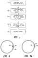
- FIG. 1 illustrates the stent fabrication method of the present invention and to Figs. 2A, 2B, 2C, 3 and 4 which are useful in understanding the method of Fig. 1.
- a stent designer first prepares a drawing of the desired stent pattern in a flat format (step 10).
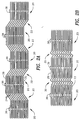
- Figs. 2A, 2B and 2C illustrate three exemplary stent pattern designs.
- the pattern of Fig. 2A has two types of sections 20 and 22. Each section 20 has two opposing periodic patterns and each section 22 has a plurality of connecting lines 24.
- the pattern of Fig. 2A can be formed of any size; a preferable size is to have each section 20 be between 1 and 6mm wide and each section 22 have connecting lines 24 of 1 6mm long. At such sizes, the pattern of Fig. 2A cannot be cut using a laser cutting system.
- the pattern of Fig. 2B is similar to that of Fig. 2A in that it also has sections 20 of opposing periodic patterns.
- the pattern of Fig. 2B also has connecting sections, labeled 30, which have a Z shape.
- Fig. 2C has no connecting sections. Instead, it has a series of alternating patterns, labeled 32 and 34.
- the patterns of Figs. 2A, 2B and 2C optionally also have a plurality of small protrusions 38 which are useful in forming the stent, as described hereinbelow.
- the stent pattern is cut into a flat piece of metal ("sheet metal").
- the metal can be any type of biocompatible material, such as stainless steel, or a material which is plated with a biocompatible material.
- the cutting operation can be implemented in any of a number of ways, such as by etching, or by cutting with a fine cutting tool, or by cutting with a very fine laser, should one become commercially available.
- step 12 is implemented with etching, then, the process is designed to cut through the sheet metal. This process is known; however, for the purposes of completeness, it will be briefly described hereinbelow.
- the drawing of the pattern is reduced and printed onto a transparent film. Since it is desired to cut completely through the metal, the drawing is printed onto two films which are joined together in a few places along their edges.
- the sheet metal is covered, on both sides, with a layer of photoresist and placed between the two transparent, printed films.
- the structure is illuminated on both sides which causes the portions of the photoresist which receive the light (which are all the empty spaces in the pattern, such as spaces 26 of Fig. 2A) to change properties.
- the sheet metal is placed into acid which eats away those portions of the photoresist which changes properties.
- the sheet metal is then placed into an etching solution which etches away all material on which there is no photoresist-removing solution which removes the photoresist, leaving the metal having the desired stent pattern.
- step 14 the metal pattern is deformed so as to cause its long sides (labeled 28 in Figs. 2A, 2B and 2C) to meet each other.
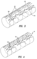
- Fig. 3 illustrates the deformation process.
- the deformation process is a rolling process, as shown.
- the protrusions 38 protrude over the edge 28 to which they are not attached. This is illustrated in Fig. 5A.
- the edges 28 are joined together by any suitable process, such as spot welding. If the protrusions 38 were made, the protrusions 38 are joined to the opposite edge 28, either by welding, adhesive or, as illustrated in Fig. 6, with a nail-like element 40.
- Fig. 5B illustrates the connection of the protrusion to the opposite edge 28. Since protrusion 38 is typically designed to extend the width of one loop 39, the pattern in approximately preserved. This is seen in Fig. 5B.
- edges 28 can be brought together and joined in the appropriate places.
- Fig. 4 illustrates a stent 31 formed by the process of steps 10 - 16 for the pattern of Fig. 2A. It is noted that such a stent has connection points 32 formed by the joining of the points 30.
- the stent 31 is polished to remove any excess material not properly removed by the cutting process (step 12).
- the polishing can be performed mechanically, by rubbing a polishing stick having diamond dust on its outside inside the stent 31.
- an electropolishing unit can be utilized.
- Fig. 7 shows an alternative embodiment of the invention in which a plurality of patterns 120 are etched and cut into the sheet metal 121 as previously discussed.
- Fig. 8 is an enlarged view of one of the plurality of patterns 120 shown in Fig. 7.
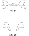
- Fig. 9 is an enlarged view of one pair 127 of the plurality of engagement troughs 128 and 129 shown in Fig. 8.
- Fig. 10 is an enlarged view of one pair 130 of the plurality of engagement protrusions 131 and 132 shown in Fig. 8.
- the sheet metal 121 and each of the patterns 120 is provided with a plurality of alignment apertures 122 and 122' adapted to receive sprockets (not shown) for precisely moving and maintaining the precise alignment of the sheet metal 121 and the patterns 120 during the various stages of manufacturing.
- Each pattern 120 has a first long side 123 and a second long side 124, a first short side 125, and a second short side 126.
- the first long side 123 is provided with a plurality of pairs 127, 127' and 127" of engagement troughs 128 and 129 (shown in greater detail in Fig. 9). Each pair 127, 127' and 127" of engagement troughs has a first engagement trough 128 and a second engagement trough 129.
- the second long side 124 is provided with a plurality of pairs 130, 130' and 130" of engagement protrusions (shown in greater detail in Fig. 10). Each pair 130, 130' and 130" of engagement protrusions is provided with a first engagement protrusion 131 and a second engagement protrusion 132.
- the pairs of engagement protrusions 130, 130' and 130" are disposed substantially opposite the pairs of engagement troughs 127, 127' and 127".
- the engagement troughs 128 and 129 are disposed and adapted to receive and engage the engagement protrusions 131 and 132 so that the alignment of the stent is maintained when the pattern 120 is deformed and the flat sheet metal is rolled so that the first long side 123 and the second long side 124 meet each other to form a tube as shown in Figs. 19 and 20.
- a bridge 133 of material is disposed between each pair 127, 127' and 127" of engagement troughs 128 and 129. This bridge 133 imparts additional stability and facilitates alignment during manufacturing and imparts additional strength to the welds of the finished stent as discussed below.
- the bridge 133 may be cut in a variety of ways well known to those skilled in the art, however, in a preferred embodiment, a laser is utilized.
- Engagement trough 128 is welded to engagement protrusion 131 and engagement trough 129 is welded to engagement protrusion 132 as shown in Figs. 12 and 13. This may be accomplished in a variety of ways well known to those skilled in the art, however, in a preferred embodiment a plurality of spot welds are utilized.
- Figs. 12 and 13 about five spot welds are used in each weld run as shown in Figs. 12 and 13.
- the heat produced by the welding melts the cut bridge 133 material and the material is drawn towards the engagement trough 128 or 129 to which the material is attached and is drawn into the welded area between the engagement trough and the engagement protrusion where the additional bridge material becomes part of and imparts additional strength to the weld.
- the stent may then be finished as previously discussed.
- Fig. 13 is an enlarged view of the welded area shown in Fig. 12.
- the weld run is offset from the point where the engagement trough and the engagement protrusion contact each other. In an especially preferred embodiment, the weld run is offset about .01 mm.
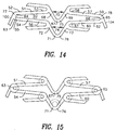
- Fig. 14 is a detailed view of the pattern shown in Fig. 8.
- Applicants' invention can also be described as an expandable stent defining a longitudinal aperture 80 having a longitudinal axis or extension 79 and a circumferential axis or extension 105, including a plurality of flexible connected cells 50 with each of the flexible cells 50 having a first longitudinal end 77 and a second longitudinal end 78.
- Each cell 50 also is provided with a first longitudinal apex 100 disposed at the first longitudinal end 77 and a second longitudinal apex 104 disposed at the second longitudinal end 78.
- Each cell 50 also includes a first member 51 having a longitudinal component having a first end 52 and a second end 53; a second member 54 having a longitudinal component having a first end 55 and a second end 56; a third member 57 having a longitudinal component having a first end 58 and a second end 59; and a fourth member 60 having a longitudinal component having a first end 61 and a second end 62.
- the stent also includes a first loop 63 defining a first angle 64 disposed between the first end 52 of the first member 51 and the first end 55 of the second member 54.
- a second loop 65 defining a second angle 66 is disposed between the second end 59 of the third member 57 and the second end 62 of the fourth member 60 and is disposed generally opposite to the first loop 63.
- a first flexible compensating member or flexible link 67 having a first end 68 and a second end 69 is disposed between the first member 51 and the third member 57 with the first end 68 of the first flexible compensating member or flexible link 67 communicating with the second end 53 of the first member 51 and the second end 69 of the first flexible compensating member or flexible link 67 communicating with the first end 58 of the third member 57.
- the first end 68 and the second end 69 are disposed a variable longitudinal distance 70 from each other.
- a second flexible compensating member 71 having a first end 72 and a second end 73 is disposed between the second member 54 and the fourth member 60.
- the first end 72 of the second flexible compensating member or flexible link 71 communicates with the second end 56 of the second member 54 and the second end 73 of the second flexible compensating member or flexible link 71 communicates with the first end 61 of the fourth member 60.
- the first end 72 and the second end 73 are disposed a variable longitudinal distance 74 from each other.
- the first and second flexible compensating member or flexible links 67 and 71 are arcuate.
- the first and second flexible compensating member or flexible links 67 and 71 are differentially extendable or compressible when the stent is bent in a curved direction away from the longitudinal axis 79 of the aperture 80. (Shown in Fig. 20.)
- the first member 51, second member 54, third member 57, and fourth member 60 and the first loop 63 and the second loop 65 and the first flexible compensating member or flexible link 67 and the second flexible compensating member or flexible link 71 are disposed so that as the stent is expanded the distance between the first flexible compensating member or flexible link 67 and the second flexible compensating member or flexible link 71 increases and the longitudinal component of the first member 51, second member 54, third member 57 and fourth member 60 decreases while the first loop 63 and the second loop 65 remain generally opposite to one another, the ends 68 and 69 of the first flexible compensating member or flexible link 67 and the ends 72 and 73 of the second flexible compensating member or flexible link 71 open so as to increase the variable longitudinal distance 70 between the first end 68 and the second
- first flexible compensating member 67 and the second flexible compensating member 71 impart support to the lumen being treated.
- Fig. 15 shows the dimensions of an especially preferred embodiment of this invention.
- the deflection points i.e., the first and second loops 63 and 65 and the first and second compensating members 67 and 71, are made wider than the first, second, third, and fourth members 51, 54, 57 and 60 so that the force of the deflection is distributed over a wider area upon the expansion of the stent.
- the deflection points can be made wider than the first, second, third and fourth members in differing amounts so that the deflection will occur in the narrower areas first due to the decreased resistance.
- the first and second compensating members are wider than the first, second, third and fourth members and the first and second loops are wider than the first and second compensating members.
- the first, second, third and fourth members 51, 54, 57 and 60 have a width of about 0.1 mm.
- the first and second loops 63 and 65 have a width of about 0.14 mm.
- the first and second compensating members 67 and 71 are provided with a thickened portion 75 and 76 having a width of about 0.12 mm.
- the first and second loops have a width that is about 40% greater and the first and second compensating members have a width that is about 20% greater than the width of the first, second, third and fourth members.
- Figs. 16 through 20 show details of a stent constructed in accordance with this invention.
- FIGs. 21 to 24 Yet another advantage of Applicant's invention is shown in Figs. 21 to 24.
- the dimensions and the degree of displacement of the components of the stents shown in Figs. 21 to 24 has been intentionally exaggerated.
- Fig. 21 is a cross-sectional front view taken along line A-A of the unexpanded stent made in accordance with applicants invention shown in Fig. 20.
- the unexpanded stent 200 of Fig. 21 is shown disposed in the lumen 202 of a blood vessel 201 prior to expansion.
- this stent is made by first cutting the stent pattern into a flat piece of sheet metal and then rolling the sheet metal into a tube to form the tubular stent.
- the first and second flexible compensating members 67 and 71 of the unexpanded stent tend to "flare out" in a direction away from the longitudinal axis or lumen of the stent.
- the flexible compensating members 67 and 71 define outer diameters which are larger than the outer diameters defined by the remaining portions of the stent.
- Fig. 22 shows the stent of Fig. 21 after it has been expanded in the lumen and against the internal wall of the blood vessel. As shown in Fig. 22, upon expansion of the unexpanded stent toward the wall of the blood vessels, the walls of the blood vessel imparts a mechanical force to the first and second flexible compensating members 67 and 71 and the compensating members move toward the longitudinal axis or lumen of the stent until they are substantially in registry with the remaining portion of the stent.
- the lumen of the expanded stent is substantially circular when viewed in cross section with substantially no portion of the expanded stent projecting into the lumen or towards the longitudinal axis of the expanded stent.
- Fig. 23 is similar to Fig. 21 except that the pattern has been cut into a tubular member using conventional methods of making stents. As shown in Fig. 23, the flexible compensating members do not flare out away from the longitudinal axis of the unexpanded stent 203. Upon the expansion of the stent shown in Fig. 23 toward the walls of the blood vessel 201, the flexible compensating members 67' and 71' tend to "flare in” and project into the lumen 204 of the expanded stent 203.
- Fig. 24 shows the stent 203 of Fig. 23 after it has been expanded in a lumen 204 of a blood vessel 201.
- the flexible compensating members 67' and 71' are not in registry with the remaining portions of the stent and define a diameter smaller than the diameter of remaining portions of the stent.
- Applicant's invention is also directed to an apparatus for fabricating a stent, comprising a platform, a mandrel, and means for deforming a sheet of metal around the mandrel.
- the platform is adapted to receive a flat sheet of metal to be formed into a stent.
- the flat sheet of metal is provided with a first end, a second end defining a longitudinal axis, a first major surface, a second major surface, a first long side, a second long side, with the first and said second long sides substantially parallel to the longitudinal axis of the sheet.
- the mandrel has a substantially cylindrical external surface and a first end and a second end defining a longitudinal axis.
- the mandrel is sized to have a cross-sectional diameter substantially equal to or less than the internal diameter of a stent to be fabricated.
- a means for securing the mandrel against a major surface of the flat sheet of metal is provided.
- a means for deforming the flat sheet of metal around the external surface of the mandrel is also provided to deform the flat sheet of metal into a substantially tubular shape that substantially conforms to the external surface of the mandrel.
- the means for deforming the sheet is adapted so that the first long side and the second long side remain substantially parallel to each other when the flat sheet of metal is deformed into a tubular shape.
- a means, e.g., a welding apparatus, laser, adhesive, or screw secures the first long side of the sheet to the second long side of the sheet.
- a plurality of stent patterns are cut or etched into a flat piece of metal.
- Each of the patterns has a first long side and a second long side, with the first long side provided with a plurality of pairs of engagement points and second long side provided with a plurality of pairs of engagement points.
- the plurality of pairs of engagement points are disposed substantially opposite each other and are sized and disposed to communicate when the pattern is deformed and rolled into a tubular shape.
- Each pair of the first long side engagement points is provided with a bridge disposed between each first long side engagement point comprising the pair, the bridge having a width that is less than the width of the other portions of the stent.
- a mandrel is disposed between the first and second long sides of the sheet.
- the mandrel has a substantially cylindrical external surface and a longitudinal axis substantially parallel to the first long side and the second long sides.
- the pattern is deformed into a tubular shape so that the first long side pairs of engagement points contact the second long side pairs of engagement points.
- the bridge is cut and each of the engagement points is attached to the engagement point with which it is in contact to form the expandable stent.
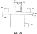
- Figs. 25 to 28 show a preferred embodiment of an apparatus for fabricating and a stent constructed in accordance with Applicants' invention.
- the apparatus comprises a laser housing 300, a laser 301, a movable table 302, and a plurality of stent folders 303 disposed on the table.
- the laser 301 is disposed within and selectively movable within the housing 300.
- the movable table 302 has a first end 304 and a second end 305 and is adapted for selective movement into and out of the laser housing 300.
- the table 302 is adapted so that when the first end 304 of the table 302 is disposed within the laser housing 300 the second end of the table 305 is disposed outside of said housing 300 and when said second end 305 of the table 302 is disposed within the laser housing 300 the first end 304 of the table 302 is disposed outside of the laser housing 300.
- a plurality of stent folders 303 is disposed at the first end 304 of the table and a plurality of stent folders 303 is disposed at the second end 305 of the table 302. As shown in FIGS. 26 and 27, each of said stent folders comprises:
- Each of the blade deforming tips has a length substantially equal to the first and the second long sides of the flat sheet of metal and in a preferred embodiment the blade deforming tips are concave as shown in FIG. 27.
- the third deforming blade tip is substantially identical to the sixth deforming blade tip; the second deforming blade tip is substantially identical to the fifth deforming blade tip; and the first deforming blade tip is substantially identical to the fourth deforming blade tip.
- a plurality of stent patterns is cut into a flat piece of metal, each of the patterns having a first major surface and a second major surface, a first long side and a second long side.
- the first long side and the second long sides are provided with a plurality of pairs of engagement points 329, 330, 331, and 332, as shown in FIGS. 28 and 29, disposed substantially opposite each other and sized and disposed to communicate when the pattern is deformed and rolled into a tubular shape.
- Each pair of the first long side engagement points is provided with a bridge 333 disposed between each first'long side engagement point 329 and 330 comprising the pair.
- the bridge 333 has a width that is less than the width of the other portions of the stent.
- the sheet is also provided with a plurality of alignment apertures 122 sized and disposed to engage the alignment pins 308 on the base 306.
- the sheet is disposed on the base so that the first major surface of the sheet is in contact with the base.
- a mandrel 309 having a substantially cylindrical external surface 310 and a longitudinal axis 313 is disposed against the second major surface of the sheet between the first long side and the second long side of the sheet with the longitudinal axis substantially parallel to the first long side and the second long side, as shown in FIG 30A.
- the pattern is deformed into a tubular shape so that the first long side pairs of engagement points contact the second long side pairs of engagement points, as shown in FIG. 29.
- the deforming step comprises the steps of:
- the laser is used to cut the bridge.
- the laser is then used to weld each of the engagement points to the engagement point with which it is in contact to form the expandable stent.
- the bridge has a width that is about 25% to about 50% of the width of the other portions of the stent and in an especially preferred embodiment the bridge has a width of about 40 microns.
- the engagement points, as shown in FIGS. 28 and 29 are sized and adapted to move in an amount sufficient so as to reduce the likelihood of material stress occurring during welding heating and cooling cycles.
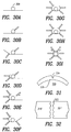
- a V-shaped notch 334 may be formed between the first long side and the second long side when the stent is deformed to provide for a stronger weld, as shown in FIG. 31.
- a gap 335 may be provided between the engagement points and the external surface of the mandrel 309 during the deforming step. This gap 335 provides a greater area for weld material, thus, strengthening the weld and reducing heat dissipation through the mandrel during welding, thus, reducing the amount of energy that must be put into the weld.
- Additional weld fill material 336 may be provided on the side of each of the engagement points substantially opposite the bridge, as shown in Figs. 33 and 34.
- the weld fill material 336 is sized and disposed so as to permit the additional weld fill material to be drawn into the weld point during welding.
- the bridge is cut using the laser.
- the first side and long sides are then connected using the laser to form a weld that is preferably wider than the other portions of the stent.
- the weld is about 20% wider than the other portions of the stent and has a width of about 140 microns.
- the weld is preferably run from outside-to-in. A plurality of welding runs is preferably used and in an especially preferred embodiment two weld-runs are utilized.
- the weld-run may be offset from the point where the engagement points contact each other and in a preferred embodiment is offset about .01 mm from the point where the engagement points contact each other.
- the weld may be a spot weld, a plurality of spot welds, and in a preferred embodiment, the weld comprises 5 spot welds.
- the pattern is cut into the sheet using multiple-up-etching and comprises the step of inspecting both sides of the sheet after etching and before the sheet is disposed on the base.
- the inspection step is carried out using an automated optical inspection apparatus.
- the stent patterns are adapted so that upon the expansion of the stent against the internal wall of a vessel substantially no portion of the stent projects into the longitudinal lumen of the stent.
- the stent may be finished by electropolishing.
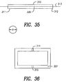
- FIGS. 37 to 40 show another embodiment of an apparatus for fabricating a stent constructed in accordance with the invention.
- a base 401 is provided with a sheet receiving area 402 and is adapted to receive a flat sheet of metal to be formed into a stent.
- the sheet receiving area 402 is also provided with a mandrel receiving groove 409.
- the flat piece of metal has a longitudinal axis, a first major surface, a second major surface, a first long side, and a second long side, with the first and the second long sides substantially parallel to the longitudinal axis.
- An arm 403 having a first end 404 and a second end 405 is provided.
- the first end 404 of the arm is adapted to selectively retain a mandrel 406 having a substantially cylindrical external surface.
- the second end of the arm 405 is hingedly connected to the base 401 and is adapted for movement in a first direction toward the base 401 and in a second direction away from the base 401 to secure the mandrel 406 against a major surface of the flat sheet of metal.
- the mandrel 406 is sized to have a cross-sectional diameter substantially equal to or less than the internal cross-sectional diameter of the stent to be fabricated.
- a means 407 is provided for deforming the flat piece of metal against and around the external surface of the mandrel so that the flat sheet of metal is deformed into a substantially tubular shape conforming to the external surface of the mandrel with the first long side and the second long side substantially parallel to each other.
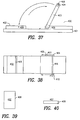
- FIG. 39 shows a top view of one embodiment wherein the means 407 for deforming is a member provided with a deforming tip 408 having a length substantially equal to the length of the first and second long sides of the sheet metal.
- the deforming tip is concave, as shown in FIG. 40.
- a sheet is placed on the sheet receiving area 402.
- a mandrel 406 is disposed in the first end 404 of the arm 403 and the arm 403 is moved in the first direction so that the mandrel is in contact with the sheet.
- the deforming means is then used to deform the sheet around the mandrel a previously discussed.
- the arm 403 is then moved in the second direction and the mandrel 406 with the sheet wrapped around it is removed from the first end 404 of the arm 403.
- the first and second long sides are then connected as previously discussed to form the stent.
- the mandrel with the sheet wrapped around it is transferred to the stent aligning and welding jig shown in FIGS. 41 to 45.
- the stent aligning and welding jig shown in FIGS. 41 to 45 comprises a base 500 having a first end and a second end provided with a first wall 501 having a first end and a second end and a first major surface 502 and a second major surface 503 and a second wall 504 having a first end and a second end and a first major surface 505 and a second major surface 506.
- the second major surface 503 of the first wall 501 and the first major surface 505 of the second wall 504 define a longitudinal U-shaped channel 507 having a longitudinal axis in the base 500.
- the first wall 501 is provided with a plurality of slots 508 defining a plurality of first clamping portions 509 having a top end 511 and a bottom end 512 and a first major surface 502 and a second major surface 503.
- Each of the first clamping portions 509 is provided with a first concave channel 510 disposed at the top end 511 of the second major surface 503 of the first clamping portion 509 and a second concave channel 513 disposed at the bottom end 512 of the second major surface 503 of the first clamping portion 509.
- the first and the second concave channels 510 and 513 are substantially parallel to the longitudinal axis of the U-shaped channel 507.
- each of the plurality of first clamping portions 509 is also provided with a compensation slit 514 disposed between the first concave channel 510 and the second concave channel 513 that is substantially parallel to the longitudinal axis of the U-shaped channel 507.
- a plurality of second clamping portions 515 is disposed in the U-shaped channel 507 between the second major surface 503 of the first wall 501 and the first major surface 505 of the second wall 504. Each of the second clamping portions 515 is disposed in registry with one of the first clamping portions 509. Each of the second clamping portions 515 has a top end 516, a bottom end 517, a first major surface 518, a second major surface 519, a first minor surface disposed at the top end, a second minor surface disposed at the bottom end, a third minor surface disposed between the top end and the bottom end, and a fourth minor surface disposed opposite the third minor surface between the top end 516 and the bottom end 517.
- Each of the second clamping portions 515 is provided with a first concave channel 521 disposed at the top end 516 of the first major surface 518 of the second clamping portion 515 and a second concave channel 522 disposed at the bottom end 517 of the first major surface 518 of the second clamping portion 515.
- the first and the second concave channels 521 and 522 are substantially parallel to the longitudinal axis of the U-shaped channel 507.
- a biasing means 523 is disposed between the first major surface 505 of the second wall 504 and the second major surface 503 of each of the of second clamping portions 509 for biasing the first major surface 518 of each of the second clamping portions 515 against the second major surface 503 of each of the first clamping portions 509 which are in registry with each other.
- a first mandrel support lever positioning pin 524 projects from the third minor surface 520 and a second mandrel support lever positioning pin 521 projects from the fourth minor surface of each of the second clamping portions 515.
- the mandrel support lever positioning pins 524 and 521 are substantially parallel to the longitudinal axis of the U-shaped channel.
- a biasing control means 522 selectively controls the distance between the second major surface 503 of each of the first clamping portions 509 and the first major surface 518 of each of the second clamping portions 515.
- a retaining mandrel 523 is disposed in the second concave channel 513 of the first wall 501 and the second concave channel 522 in each of the second clamping portions 515.
- a mandrel support lever 534 supports the stent during the alignment of the first long side of the sheet with the second long side of the sheet.
- the lever 534 is provided with a first mandrel support notch 525 for supporting the first end of the mandrel and a second mandrel support notch 526 for supporting the second end of the mandrel.
- a first mandrel support lever positioning pin engagement surface 527 engages the first mandrel support lever positioning pin 524 and a second mandrel support lever positioning pin engagement surface 528 engages the second mandrel support lever positioning pin 521 when the mandrel support lever is disposed on the second wall 504.
- the biasing control means 522 is a threaded screw disposed in each of the first clamping portions 509 with each of the screws 522 communicating with the first major surface 502 and the second major surface 503 of each of the first clamping portions 509.
- the screws 522 are selectively movable in a direction toward and away from the first major surface 518 of the second clamping portion 515 to selectively move the second clamping portion 515 in a direction toward and away from the first clamping portions 509 to selectively vary the distance between the second major surface 503 of each of the first clamping portions 509 and the first major surface 518 of each of the second clamping portions 515.
- the mandrel with the sheet wrapped around it is secured in the first concave channels 510 and 521.
- the biasing control means 522 e.g., a screw, is adjusted to secure the mandrel in the first concave channels while permitting the first and second long sides of the sheet to be adjusted so that the contact points are aligned as desired.
- the mandrel support lever shown in FIG. 42 is utilized to support the mandrel during the alignment operation.
- the first mandrel support notch supports the first end of the mandrel and the second mandrel support notch supports the second end of the mandrel.
- the first mandrel support lever positioning pin surface 527 engages the first mandrel support lever positioning pin 524 and the second mandrel support lever positioning pin surface 528 engages the second mandrel support positioning pin 521 so as to align the mandrel support lever 534 when it is supporting the mandrel.
- FIGS. 46 to 48 show a jig 612 for electropolishing a tubular stent, comprising a rack 600 having a first end 601 and a second end 602 and provided with a plurality of stent electropolishing mounts 603.
- Each of the mounts 603 is provided with a base 604 and an electrically conductive first member 605 having a first end 606 connected to the base 604 and a second end 607 adapted to selectively contact the external surface of the tubular stent to be electropolished without damaging its external surface.
- the mounts 603 are also provided with an electrically non-conductive second member 608 having a first end 609 connected to the base and a second end 610 adapted to be selectively disposed within the longitudinal bore of the stent without damaging the surface defining the longitudinal bore.
- the first member 605 and the second member 608 are also adapted so as to bias the second end 610 of the second member 608 towards the second end 607 of the first member 605 in an amount sufficient to secure the stent between said first and the second members 605 and 608.
- the advantage of a mount constructed in accordance with applicants' invention is that the electrically conductive member 605 contacts the external surface of the stent. This reduces the likelihood of undulations and erosion lines occurring on the surface defining the longitudinal bore.
- Electropolishing a stent with Applicants' mount reduces the likelihood that the longitudinal lumen of the stent will have an irregular surface which could result in turbulent fluid flow which could result in thrombosis or platelet aggregation.
- a stent is placed on a rack constructed as previously discussed.
- the method comprises immersing the stent in an electropolishing bath and applying electrical current to the first member for a predetermined period of time; and changing the point where the second end of the first member contacts the external surface of the stent prior to the expiration of the predetermined period of time.
- Changing the point of contact minimizes the concentration of undulations or erosion lines at any given point on the stent near the point of contact of the electrically conductive member.
- the point of contact may be changed by rotating the stent.
- the point of contact is changed by varying the distance between the stent and the base by longitudinally moving the stent toward or away from the base 604 as shown in FIGS.
- the point of contact is changed at about the midpoint of the predetermined period of time.
- the treatment is interrupted before the expiration of the predetermined time, the effect of the electropolishing prior to the interruption step is evaluated, and the remaining period of the predetermined time is adjusted to compensate for any variations in the amount of material actually removed prior to the interruption step.
- the treatment may be interrupted at any time, however, interruption at about the midpoint of the predetermined period of time is preferred.
- Pieces of sacrificial material 611 may be added at the first end 601 and the second end 602 of the rack 600 to compensate for the additional material normally removed from stents disposed at the first end and the second end of the rack as shown in FIG 48.
- the material is selected and added in an amount sufficient to substantially equalize the amount of additional material normally removed from the stents disposed first and second ends of the rack.
- the stent is manufactured as previously discussed however, when deforming the pattern into a tubular shape so that the first long side pairs of engagement points contact the second long side pairs of engagement points, a portion of the stent is allowed to remain attached to the sheet of metal, as shown in FIGS. 49 and 50 (which is an end view taken along line A-A of FIG. 49) .
- the bridge is then cut, the engagement points are connected to form the stent, the stent is electropolished by connecting an electrode to the sheet, and the stent is then removed from the sheet. This reduces the likelihood of damage to the stent because the sheet to which the stent is attached is disposable.
- This method also provides an additional advantage because the disposable sheet to which the stent is attached acts as sacrificial material as previously discussed.
Abstract
Description
a) a flat piece of sheet metal provided with a plurality of stent patterns, each of the patterns having a first long side and a second long side, the first long side provided with a plurality of pairs of engagement points, the second long side provided with a plurality of pairs of engagement points, the plurality of pairs of engagement points disposed substantially opposite each other, the engagement points sized and disposed to communicate when the pattern is deformed and rolled into a tubular shape, each pair of the first long side engagement points provided with a bridge disposed between each first long side engagement point comprising the pair, the bridge having a width that is less than the width of the other portions of the stent.
- d) utilizing the laser in cutting the bridge; and
- e) utilizing the laser in welding each of the engagement points to the engagement point with which it is in contact to form the expandable stent.
Claims (137)
- Apparatus for fabricating a stent, comprising:a) a platform adapted to receive a flat sheet of metal to be formed into said stent, said flat sheet of metal having a longitudinal axis, a first major surface, a second major surface, a first long side, and a second long side, said first and said second long sides substantially parallel to said longitudinal axis of said sheet;b) a mandrel having a substantially cylindrical external surface and having a first end and a second end defining a longitudinal axis, said mandrel sized to have a cross-sectional diameter substantially equal to or less than the internal diameter of said stent to be fabricated;c) means for securing said mandrel against a major surface of said flat sheet of metal; andd) means for deforming said flat sheet of metal against said external surface of said mandrel so that said flat sheet of metal is deformed into a substantially tubular shape, said means for deforming adapted so that said first long side and said second long side remain substantially parallel to each other when said flat sheet of metal is deformed into said tubular shape.
- The apparatus of claim 1, further comprising means for securing said first long side of said sheet to said second long side of said sheet.
- The apparatus of claim 2, wherein said means for securing is a welding apparatus.
- The apparatus of claim 3, wherein said welding apparatus is a laser.
- The apparatus of claim 1, wherein said platform is provided with a concave recess to receive said mandrel.
- The apparatus of claim 1, wherein said means for securing said mandrel is a hingedly connected arm adapted for movement in a first direction toward said platform and in a second direction away from said platform.
- The apparatus of claim 1, wherein the apparatus is adapted to provide a substantially V-shaped notch between said first long side and said second long side when said sheet is deformed into said tubular shape.
- Apparatus for fabricating a stent, comprising:a) a base having a platform adapted to receive a flat sheet of metal to be formed into said stent, said flat sheet of metal having a longitudinal axis, a first major surface, a second major surface, a first long side, and a second long side, said first and said second long sides substantially parallel to said longitudinal axis of said stent;b) a mandrel having a substantially cylindrical external surface and having a first end and a second end defining a longitudinal axis, said mandrel sized to have a cross-sectional diameter substantially equal to or less than the internal diameter of said stent to be fabricated;c) means for securing said mandrel against a major surface of said flat sheet of metal;d) a plurality of deforming blades disposed around the periphery of said mandrel for deforming said flat sheet of metal against said external surface of said mandrel so that said flat sheet of metal is deformed into a substantially tubular shape, said blades disposed between said first end and said second end of said mandrel, each of said deforming blades adapted for independent and selective movement in a first direction toward said mandrel and a second direction away from said mandrel so as to selectively impinge upon said mandrel or upon a portion of said sheet disposed between said mandrel and each of said deforming blades, each of said deforming blades further adapted so that said first long side and said second long side of said sheet remain substantially parallel to each other when said stent is deformed into said tubular shape;e) means for selectively moving each of said deforming blades in a first direction toward said mandrel and in a second direction away from said mandrel; andf) means for securing said first long side of said sheet to said second long side of said sheet.
- The apparatus of claim 8, wherein said means for securing said first long side of said sheet to said second long side of said sheet is a welding apparatus.
- The apparatus of claim 9, wherein said welding apparatus is a laser.
- The apparatus of claim 8, wherein said plurality of deforming blades comprises six blades.
- The apparatus of claim 8, wherein said means for securing said mandrel is a hingedly connected arm adapted for movement in a first direction toward said platform and in a second direction away from said platform.
- The apparatus of claim 8, wherein said base is provided with a first concave recess for receiving said first end of said mandrel and a second concave recess for receiving said second end of said mandrel.
- The apparatus of claim 8, wherein said means for selectively moving each of said deforming blades is an electric motor.
- The apparatus of claim 8 further comprising means for controlling the sequence and degree to which each of said blades impinges upon said mandrel or a portion of said sheet disposed between said mandrel and each of said deforming blades.
- The apparatus of claim 15, wherein said means for controlling is a computer.
- The apparatus of claim 8, further comprising an alignment means disposed on said base and adapted to engage and align said metal sheet.
- The apparatus of claim 8, wherein a plurality of said deforming blades are adapted to secure said first long side and said second long side against said external surface of said mandrel while permitting a laser to contact said first long side and said second long side to secure said first long side to said second long side.
- The apparatus of claim 18, wherein a plurality of said deforming blades are provided with a plurality of scalloped apertures, said apertures sized and disposed to permit said plurality of blades to secure said first long side and said second long side against said external surface of said mandrel while providing access to said laser to predetermined portions of said first side and said long side to secure said first long side to said second long side.
- Apparatus for fabricating a stent, comprising:a) a laser housing;b) a laser disposed within and selectively movable within said housing;c) a movable table having a first end and a second end and adapted for selective movement into and out of said laser housing, said table adapted so that when said first end of said table is disposed within said laser housing said second end of said table is disposed outside of said housing and when said second end of said table is disposed within said laser housing said first end of said table is disposed outside of said laser housing;d) a plurality of stent folders disposed at said first end of said table and a plurality of stent folders disposed at said second end of said table, each of said stent folders comprising:a) a base having a platform adapted to receive a flat sheet of metal to be formed into said stent, said flat sheet of metal having a longitudinal axis, a first major surface, a second major surface, a first long side, and a second long side, said first and said second long sides substantially parallel to said longitudinal axis, said sheet provided with a plurality of alignment of apertures;b) a plurality of alignment pins projecting from each of said platforms, said pins sized to engage said alignment apertures and align said sheet on said platform;c) a mandrel having a substantially cylindrical external surface and having a first end, a second end, and a longitudinal axis, said mandrel sized to have a cross-sectional diameter substantially equal to or less than the internal diameter of said stent to be fabricated, said platform provided with a first concave recess adapted to receive said first end of said mandrel and a second concave recess adapted to receive said second end of said mandrel;d) a hingedly connected arm adapted for movement in a first direction toward said platform and in a second direction away from said platform for securing said mandrel against a major surface of said flat sheet of metal;e) a first deforming blade provided with a first deforming blade tip; a second deforming blade provided with a second deforming blade tip; a third deforming blade provided with a third deforming blade tip; a fourth deforming blade provided with a fourth deforming blade tip; a fifth deforming blade provided with a fifth deforming blade tip; and a sixth deforming blade provided with a sixth deforming blade tip, said blades disposed around said external surface of said mandrel, said deforming blade tips adapted to deform said flat sheet of metal against said external surface of said mandrel so that said flat sheet of metal is deformed into a substantially tubular shape substantially conforming to said external surface, said deforming blades disposed between said first end and said second end of said mandrel, each of said deforming blades adapted for independent and selective movement in a first direction toward said mandrel and a second direction away from said mandrel so as to selectively impinge said deforming blade tips against said mandrel or upon a portion of said sheet disposed between said mandrel and each of said deforming blade tips, each of said deforming blades further adapted so that said first long side and said second long side of said sheet remain substantially parallel to each other when said stent is deformed into said tubular shape, said third and said sixth deforming blade tips provided with a plurality of scalloped laser apertures, said apertures sized and disposed to permit said third and said sixth deforming blade tips to secure said first long side and said second long side against said external surface of said mandrel while providing said laser access to predetermined portions of said first long side and said second long side in order to weld said first long side to said second long side;f) a first motor connected to said first deforming blade; a second motor connected to said second deforming blade; a third motor connected to said third deforming blade; a fourth motor connected to said fourth deforming blade; a fifth motor connected to said fifth deforming blade; and a sixth motor connected to said sixth deforming blade, each of said motors adapted for selectively moving each of said deforming blades to which it is connected in a first direction toward said mandrel and in a second direction away from said mandrel; andg) a computer for controlling: the sequence which said first end of said table and said second end of said table are disposed within said laser housing; for controlling the sequence and degree to which each of said plurality of deforming blade tips impinges upon said mandrel or a portion of said sheet disposed between said mandrel and each of said deforming blade tips; and for controlling the sequence, pattern, location, and amount of energy said laser applies to each of said first and second long sides of each of said sheets disposed on each of said plurality of stent folders.
- The apparatus of claim 20, wherein each of said blade deforming tips has a length substantially equal to said first and said second long sides of said flat sheet of metal.
- The apparatus of claim 20 wherein said deforming blade tips are concave.
- The apparatus of claim 20 wherein said third deforming blade tip is substantially identical to said sixth deforming blade tip; said second deforming blade tip is substantially identical to said fifth deforming blade tip; and said first deforming blade tip is substantially identical to said fourth deforming blade tip.
- Apparatus for fabricating a stent, comprising:a) a base;b) a sheet receiving area disposed on said base, said area adapted to receive a flat sheet of metal to be formed into said stent, said flat sheet of metal having a longitudinal axis, a first major surface, a second major surface, a first long side, and a second long side, said first and said second long sides substantially parallel to said longitudinal axis;c) an arm having a first end and a second end, said first end of said arm adapted to selectively retain a mandrel having a substantially cylindrical external surface, said second end of said arm hingedly connected to said base and adapted for movement in a first direction toward said base and in a second direction away from said base and further adapted to secure said mandrel against a major surface of said flat sheet of metal disposed on said stent receiving area disposed on said base, said mandrel sized to have a cross-sectional diameter substantially equal to or less than the internal cross-sectional diameter of said stent to be fabricated;d) means for deforming said flat piece of metal against said external surface of said mandrel so that said flat sheet of metal is deformed into a substantially tubular shape substantially conforming to said external surface of said mandrel with said first long side and said second long side substantially parallel to each other.
- The apparatus of claim 24, wherein said means for deforming is a member provided with a deforming tip having a length substantially equal to said first and said second long sides of said sheet of metal.
- The apparatus of claim 24, wherein said deforming tip is concave.
- A stent aligning and welding jig comprising:a) a base having a first end and a second end, a first wall having a first end and a second end and a first major surface and a second major surface; a second wall having a first end and a second end and a first major surface and a second major surface, said second major surface of said first wall and said first major surface of said second wall defining a longitudinal U-shaped channel having a longitudinal axis in said base, said first wall provided with a plurality of slots defining a plurality of first clamping portions having a top end and a bottom end and a first major surface and a second major surface, each of said first clamping portions provided with a first concave channel disposed at said top end of said second major surface of said first clamping portion and a second concave channel disposed at said bottom end of said second major surface of said first clamping portion, said first and said second concave channels substantially parallel to said longitudinal axis of said U-shaped channel; said first wall of each of said plurality of first clamping portions provided with a compensation slit disposed between said first concave channel and said second concave channel, said compensation slit substantially parallel to said longitudinal axis of said U-shaped channel;b) a plurality of second clamping portions disposed in said U-shaped channel between said second major surface of said first wall and said first major surface of said second wall, each of said second clamping portions disposed in registry with one of said first clamping portions, each of said second clamping portions having a top end, a bottom end, a first major surface, a second major surface, a first minor surface disposed at said top end, a second minor surface disposed at said bottom end, a third minor surface disposed between said top end and said bottom end, and a fourth minor surface disposed opposite said third minor surface between said top end and said bottom end, each of said second clamping portions provided with a first concave channel disposed at said top end of said first major surface of said second clamping portion and a second concave channel disposed at said bottom end of said first major surface of said second clamping portion, said first and said second concave channels substantially parallel to said longitudinal axis of said U-shaped channel;c) a biasing means disposed between said first major surface of said second wall and said second major surface of each of said plurality of second clamping portions for biasing said first major surface of each of said second clamping portions against said second major surface of each of said first clamping portions which are in registry with each other;d) a first mandrel support lever positioning pin projecting from said third minor surface and a second mandrel support lever positioning pin projecting from said fourth minor surface of each of said second clamping portions, said mandrel support lever positioning pins substantially parallel to said longitudinal axis of said U-shaped channel;e) a biasing control means for selectively controlling the distance between said second major surface of each of said first clamping portions and said first major surface of each of said second clamping portions;f) a retaining mandrel disposed in said second concave channel of said first wall and said second concave channel in each of said second clamping portions; andg) a mandrel support lever for supporting said stent during the alignment of said first long side of said sheet with said second long side of said sheet, said lever provided with a first mandrel support notch for supporting said first end of said mandrel, a second mandrel support notch for supporting said second end of said mandrel, a first mandrel support lever positioning pin engagement surface for engaging said first mandrel support lever positioning pin and a second mandrel support lever positioning pin engagement surface for engaging said second mandrel support lever positioning pin when said mandrel support lever is disposed on said second wall.
- The apparatus of claim 27, wherein said biasing means is an elastic material.
- The apparatus of claim 28, wherein said elastic material is rubber.
- The apparatus of claim 28, wherein said elastic material is a spring.
- The apparatus of claim 27, wherein said biasing control means is a threaded screw disposed in each of said first clamping portions, each of said screws communicating with said first major surface and said second major surface of each of said first clamping portions and selectively movable in a direction toward and away from said first major surface of said second clamping portion to selectively move said second clamping portion in a direction toward and away from said first clamping portions to selectively vary the distance between said second major surface of each of said first clamping portions and said first major surface of each of said second clamping portions.
- A method of fabricating a stent comprising the steps of:a) providing a plurality of stent patterns into a flat piece of metal, each of said patterns having a first long side and a second long side, said first long side provided with a plurality of pairs of engagement points, said second long side provided with a plurality of pairs of engagement points, said plurality of pairs of engagement points disposed substantially opposite each other, said engagement points sized and disposed to communicate when said pattern is deformed and rolled into a tubular shape, each pair of said first long side engagement points provided with a bridge disposed between each first long side engagement point comprising the pair, said bridge having a width that is less than the width of the other portions of said stent;b) disposing a mandrel having a substantially cylindrical external surface and a longitudinal axis between said first long side and said second long side of said sheet, said longitudinal axis substantially parallel to said first long side and said second long side;c) deforming said pattern into a tubular shape so that said first long side pairs of engagement points contact said second long side pairs of engagement points;d) cutting said bridge; ande) attaching each of said engagement points to the engagement point with which it is in contact to form said expandable stent.
- The method of claim 32, wherein said bridge has a width that is about 25% to about 50% of the width of the other portions of said stent.
- The method of claim 33, wherein said bridge has a width of about 40 microns.
- The method of claim 32, wherein said engagement points are sized and adapted to move in an amount sufficient so as to reduce the likelihood of material stress occurring during welding heating and cooling cycles.
- The method of claim 32, further comprising the step of forming a V-shaped notch between said first long side and said second long side during step c).
- The method of claim 32, further comprising the step of providing a gap between said engagement points and said external surface of said mandrel during step c).
- The method of claim 32, comprising the additional step of providing additional weld fill material on the side of each of said engagement points substantially opposite said bridge, said weld fill material sized and disposed so as to permit the additional weld fill material to be drawn into the weld point during welding.
- The method of claim 32, further comprising the step of providing said sheet with a plurality of alignment apertures.
- The method of claim 32, wherein step d) is carried out using a laser.
- The method of claim 32, wherein step e) is carried out utilizing a weld.
- The method of claim 40, wherein said weld is run from outside-to-in.
- The method of claim 40, wherein said weld is wider than the other portions of the stent.
- The method of claim 42, wherein said weld is about 20% wider than the other portions of the stent.
- The method of claim 41, wherein said weld has a width of about 140 microns.
- The method of claim 41, wherein step e) is carried out using a welding run that is offset from the point where said engagement points contact each other.
- The method of claim 41, wherein step e) is carried out using a plurality of welding runs.
- The method of claim 47, wherein two welding runs are utilized.
- The method of claim 46, wherein said weld run is offset about .01 mm from the point where said engagement points contact each other.
- The method of claim 42, wherein said weld is a spot weld.
- The method of claim 50, wherein a plurality of spot welds is utilized.
- The method of claim 51, wherein 5 spot welds are utilized.
- The method of claim 34, further comprising the step of electropolishing the stent.
- The method of claim 34, wherein step e) is carried out utilizing an adhesive.
- The method of claim 34, wherein step e) is carried out utilizing a nail-like element.
- The method of claim 34, wherein said pattern in cut into said stent using multiple-up-etching.
- The method of step 34, further comprising the step of inspecting both sides of said sheet after step a) and before step b).
- The method of claim 57, wherein said inspection step is carried out using an automated optical inspection apparatus.
- A jig for electropolishing a tubular stent, comprising:
a rack having a first end and a second end, said rack provided with a plurality of stent electropolishing mounts, each of said mounts havinga) a base;b) an electrically conductive first member having a first end connected to said base and a second end adapted to selectively contact the external surface of said tubular stent without damaging said external surface;c) an electrically non-conductive second member having a first end connected to said base and a second end adapted to be selectively disposed within the longitudinal bore of said stent without damaging said longitudinal bore, said first member and said second member further adapted so as to bias said second end of said second member towards said second end of said first member in an amount sufficient to secure said stent between said first and said second members. - A method of electropolishing a stent, comprising the steps of:a) mounting a stent on a rack, said rack having a first end and a second end provided with a plurality of stent electropolishing mounts, each of said mounts having a base; an electrically conductive first member having a first end connected to said base and a second end adapted to selectively contact the external surface of said tubular stent without damaging said external surface; an electrically non-conductive second member having a first end connected to said base and a second end adapted to be selectively disposed within the longitudinal bore of said stent without damaging said longitudinal bore, said first member and said second member further adapted so as to bias said second end of said second member towards said second end of said first member in an amount sufficient to secure said stent between said first and said second members;b) immersing said stent in an electropolishing bath and applying electrical current to said first member for a predetermined period of time; andc) changing the point where said second end of said first member contacts said external surface of said stent prior to the expiration of said predetermined period of time.
- The method of claim 60, wherein point of contact is changed by rotating said stent.
- The method of claim 60, wherein the point of contact is changed by varying the distance between said stent and said base.
- The method of claim 60, wherein the point of contact is changed at about the midpoint of the predetermined period of time.
- The method of claim 60, further comprising the step of interrupting the treatment before the expiration of the predetermined time, evaluating the effect of the electropolishing prior to the interruption step, and adjusting the remaining period of the predetermined time to compensate for any variations in the amount of material actually removed prior to the interruption step.
- The method of claim 60, wherein the treatment is interrupted at about the midpoint of said predetermined period of time.
- The method of claim 60, further comprising the step of adding pieces of sacrificial material at said first end and said second end of said rack to substantially compensate for the additional material normally removed from stents disposed at said first end and said second end of said rack, said material selected and added in an amount sufficient to substantially equalize the amount of additional material normally removed from the stents disposed at said first end and said second end of said rack.
- A method of fabricating a stent having a longitudinal lumen comprising the steps of:a) providing a plurality of stent patterns in a flat sheet of metal; each of said patterns having a first long side and a second long side, said first long side provided with a plurality of pairs of engagement points, said second long side provided with a plurality of pairs of engagement points, said plurality of pairs of engagement points disposed substantially opposite each other, said engagement points sized and disposed to communicate when said pattern is deformed and rolled into a tubular shape, each pair of said first long side engagement points provided with a bridge disposed between each first long side engagement point comprising said pair, said bridge having a width that is less than the width of the other portions of said stent;b) disposing a mandrel having a substantially cylindrical external surface and a longitudinal axis between said first long side and said second long side of said sheet, said longitudinal axis substantially parallel to said first and said second long sides;c) deforming said pattern into a tubular shape so that said first long side pairs of engagement points contact said second long side pairs of engagement points and allowing a portion of said stent to remain attached to said sheet of metal;d) cutting said bridge;e) attaching each of said engagement points to the engagement point with which it is in contact to form said stent;f) attaching an electrode to said sheet of metal;g) electropolishing said stent; andf) disconnecting said stent from said sheet.
- The method of claim 67, wherein said bridge has a width that is about 25% to about 50% of the width of -the other portions of said stent.
- The method of claim 67, wherein said bridge is provided with a width of about 40 microns.
- The method of claim 67, wherein said engagement points are sized and adapted to move in an amount sufficient so as to reduce the likelihood of material stress occurring during welding heating and cooling cycles.
- The method of claim 67, comprising the additional step of providing additional weld fill material on the side of said engagement points substantially opposite said bridge, said weld fill material sized and disposed at said engagement points so as to permit the additional weld fill material to be drawn into the weld point during welding.
- The method of claim 67, further comprising the step of forming a V-shaped notch between said first long side and said second long side during step c).
- The method of claim 67 further comprising the step of providing a gap between said engagement points and said external surface of said mandrel during step c).
- The method of claim 67, further comprising the step of providing said sheet with a plurality of alignment apertures.
- The method of claim 67, wherein step d) is carried out using a laser.
- The method of claim 67, wherein step e) is carried out utilizing a weld.
- The method of claim 76, wherein said weld is run from outside-to-in.
- The method of claim 76, wherein said weld is wider than the other portions of the stent.
- The method of claim 78, wherein said weld is about 20% wider than the other portions of the stent.
- The method of claim 76, wherein said weld has a width of about 140 microns.
- The method of claim 76, wherein step e) is carried out using a weld-run that is offset from the point where said engagement points contact each other.
- The method of claim 76, wherein step e) is carried out using a plurality of welding runs.
- The method of claim 82, wherein two welding runs are utilized.
- The method of claim 81, wherein said weld run is offset about .01 mm from the point where said engagement points contact each other.
- The method of claim 76, wherein said weld is a spot weld.
- The method of claim 76, wherein a plurality of spot welds is utilized.
- The method of claim 86, wherein said plurality of spot welds comprises 5 spot welds.
- The method of claim 67, wherein step e) is carried Out utilizing an adhesive.
- The method of claim 67, wherein step e) is carried out utilizing a nail-like element.
- The method of claim 67, wherein said pattern in cut into said stent using multiple-up-etching.
- The method of claim 67, further comprising the step of inspecting both sides of said sheet after step a) and before step b).
- The method of claim 91, wherein said inspection step is carried out using an automated optical inspection apparatus.
- The method of claim 67, wherein said stent patterns are adapted so that upon expansion of said stent against the internal wall of a vessel substantially no portion of said stent protrudes into said longitudinal lumen of said stent.
- A sheet for fabricating a stent having a longitudinal lumen comprising:
a) a flat piece of sheet metal provided with a plurality of stent patterns, each of said patterns having a first long side and a second long side, said first long side provided with a plurality of pairs of engagement points, said second long side provided with a plurality of pairs of engagement points, said plurality of pairs of engagement points disposed substantially opposite each other, said engagement points sized and disposed to communicate when said pattern is deformed and rolled into a tubular shape, each pair of said first long side engagement points provided with a bridge disposed between each first long side engagement point comprising said pair, said bridge having a width that is less than the width of the other portions of the stent. - The sheet of claim 94, wherein said bridge has a width that is about 25% to about 50% of the width of the other portions of said stent.
- The sheet of claim 94, wherein said bridge has a width of about 40 microns.
- The sheet of claim 94, wherein said engagement points are sized and adapted to move in an amount sufficient so as to reduce the likelihood of material stress occurring during welding heating and cooling cycles.
- The sheet of claim 94, further comprising, additional weld fill material on the side of each of said engagement points substantially opposite said bridge, said weld fill material sized and disposed so as to permit the additional weld fill material to be drawn into the weld point during welding.
- The sheet of claim 94, further comprising a plurality of alignment apertures disposed in said sheet.
- The sheet of claim 94, wherein said stent patterns are adapted so that upon expansion of said sent against the internal wall of a vessel substantially no portion of said stent protrudes into said longitudinal lumen of said stent.
- A method for fabricating a stent having a longitudinal lumen, comprising the steps of:a.) constructing an apparatus comprising:a) a laser housing;b) a laser disposed within and selectively movable within said housing;c) a movable table having a first end and a second end and adapted for selective movement into and out of said laser housing said table adapted so that when said first end of said table is disposed within said laser housing said second end of said table is disposed outside of said housing and when said second end of said table is disposed within said laser housing said first end of said table is disposed outside of said laser housing;d) a plurality of stent folders disposed at said first end of said table and a plurality of stent folders disposed at said second end of said table, each of said stent folders comprising:a) a base having a platform adapted to receive a flat sheet of metal to be formed into said stent, said flat sheet of metal having a longitudinal axis, a first major surface, a second major surface, a first long side, and a second long side, said first and said second long sides substantially parallel to said longitudinal axis, said sheet provided with a plurality of alignment of apertures;b) a plurality of alignment pins projecting from each of said platforms, said pins sized to engage said alignment apertures and align said sheet on said platform;c) a mandrel having a substantially cylindrical external surface and having a first end, a second end, and a longitudinal axis, said mandrel sized to have a cross-sectional diameter substantially equal to or less than the internal diameter of said stent to be fabricated, said platform provided with a first concave recess adapted to receive said first end of said mandrel and a second concave recess adapted to receive said second end of said mandrel;d) a hingedly connected arm adapted for movement in a first direction toward said platform and in a second direction away from said platform for securing said mandrel against a major surface of said flat sheet of metal;e) a first deforming blade provided with a first deforming blade tip; a second deforming blade provided with a second deforming blade tip; a third deforming blade provided with a third deforming blade tip; a fourth deforming blade provided with a fourth deforming blade tip; a fifth deforming blade provided with a fifth deforming blade tip; and a sixth deforming blade provided with a sixth deforming blade tip, said blades disposed around said external surface of said mandrel, said deforming blade tips adapted to deform said flat sheet of metal against said external surface of said mandrel so that said flat sheet of metal is deformed into a substantially tubular shape substantially conforming to said external surface, said deforming blades disposed between said first end and said second end of said mandrel, each of said deforming blades adapted for independent and selective movement in a first direction toward said mandrel and a second direction away from said mandrel so as to selectively impinge said deforming blade tips against said mandrel or against a portion of said sheet disposed between said mandrel and each of said deforming blade tips, each of said deforming blades further adapted so that said first long side and said second long side of said sheet remain substantially parallel to each other when said stent is deformed into said tubular shape, said third and said sixth deforming blade tips provided with a plurality of scalloped laser apertures, said apertures sized and disposed to permit said third and said sixth deforming blade tips to secure said first long side and said second long side against said external surface of said mandrel while providing said laser access to predetermined portions of said first long side and said second long side of said sheet in order to weld said first long side to said second long side;f) a first motor connected to said first deforming blade; a second motor connected to said second deforming blade; a third motor connected to said third deforming blade; a fourth motor connected to said fourth deforming blade; a fifth motor connected to said fifth deforming blade; and a sixth motor connected to said sixth deforming blade, each of said motors adapted for selectively moving each of said deforming blades to which it is connected in a first direction toward said mandrel and in a second direction away from said mandrel; andg) a computer for controlling: the sequence which said first end of said table and said second end of said table are disposed within said laser housing; for controlling the sequence and degree to which each of said plurality of deforming blade tips impinges upon said mandrel or a portion of said sheet disposed between said mandrel and each of said deforming blade tips; and for controlling the sequence, pattern, location, and amount of energy said laser applies to each of said first and said second long sides of each of said sheets disposed on each of said plurality of stent folders;b.) cutting a plurality of stent patterns into a flat piece of metal, each of said patterns having a first major surface and a second major surface, a first long side and a second long side, said first long side provided with a plurality of pairs of engagement points, said second long side provided with a plurality of pairs of engagement points, said plurality of pairs of engagement points disposed substantially opposite each other, said engagement points sized and disposed to communicate when said pattern is deformed and rolled into a tubular shape, each pair of said first long side engagement points provided with a bridge disposed between each first long side engagement point comprising the pair, said bridge having a width that is less than the width of the other portions of the stent, said sheet provided with a plurality of alignment apertures sized and disposed to engage said alignment pins on said base;c.) disposing said sheet on said base so that said first major surface of said sheet is in contact with said base;d.) disposing a mandrel having a substantially cylindrical external surface and a longitudinal axis against said second major surface of said sheet between said first long side and said second long side of said sheet, said longitudinal axis substantially parallel to said first long side and said second long side;e.) deforming said pattern into a tubular shape so that said first long side pairs of engagement points contact said second long side pairs of engagement points said deforming step comprising the steps of:a) actuating said sixth deforming blade motor so that said sixth deforming blade motor moves said sixth deforming blade in said first direction in an amount sufficient for said sixth deforming blade tip to contact said external surface of said mandrel so as to secure said mandrel against said sheet;b) actuating said first deforming blade motor so that said first blade deforming motor moves said first deforming blade in said first direction in an amount sufficient for said first blade deforming tip to contact said first major surface of said sheet and deform said sheet against said external surface of said mandrel;c) actuating said second deforming blade motor so that said second deforming blade motor moves said second deforming blade in said first direction in an amount sufficient for said second deforming blade tip to contact said first major surface of said sheet and deform said sheet against said external surface of said mandrel;d) actuating said third deforming blade motor so that said third deforming blade motor moves said second deforming blade in said first direction in an amount sufficient for said third deforming blade tip to contact said first major surface of said sheet and deform said sheet against said external surface of said mandrel while actuating said sixth deforming blade motor so that said sixth deforming blade moves in said second direction away from said mandrel;e) actuating said fourth deforming blade motor so that said fourth deforming blade motor moves said fourth deforming blade tip in said first direction in an amount sufficient for said fourth deforming blade tip to contact said first major surface of said sheet and deform said sheet against said external surface of said mandrel;f) actuating said fifth deforming blade motor so that said fifth deforming blade motor moves said fifth deforming blade in said first direction in an amount sufficient for said fifth deforming blade tip to contact said first major surface of said sheet and deform said sheet against said external surface of said mandrel;g) actuating said sixth deforming blade motor so that said sixth deforming blade motor moves said second deforming blade in said first direction in an amount sufficient for said second deforming blade tip to contact said first major surface of said sheet and deform said sheet against said external surface of said mandrel;h) simultaneously actuating said third and sixth deforming blade motors so that said third and sixth deforming blade motors move said third and sixth deforming blades in said first direction in an amount sufficient for said third and sixth deforming blade tips to contact said first major surface of said sheet and deform said sheet against said external surface of said mandrel;d) utilizing said laser in cutting said bridge; ande) utilizing said laser in welding each of said engagement points to the engagement point with which it is in contact to form said expandable stent.
- The method of claim 101, wherein said bridge has a width that is about 25% to about 50% of the width of the other portions of said stent.
- The method of claim 101, wherein said bridge has a width of about 40 microns.
- The method of claim 101, wherein said engagement points are sized and adapted to move in an amount sufficient so as to reduce the likelihood of material stress occurring during welding heating and cooling cycles.
- The method of claim 101, further comprising the step of forming a V-shaped notch between said first long side and said second long side during step e).
- The method of claim 101, further comprising the step of providing a gap between said engagement points and said external surface of said mandrel during step e).
- The method of claim 101, comprising the additional step of providing additional weld fill material on the side of each of said engagement points substantially opposite said bridge, said weld fill material sized and disposed so as to permit the additional weld fill material to be drawn into the weld point during welding.
- The method of claim 101, wherein step d) is carried out using a laser.
- The method of claim 101, wherein step e) is carried out utilizing a weld.
- The method of claim 109, wherein said weld is run from outside-to-in.
- The method of claim 109, wherein said weld is wider than the other portions of the stent.
- The method of claim 111, wherein said weld is about 20% wider than the other portions of the stent.
- The method of claim 109, wherein said weld has a width of about 140 microns.
- The method of claim 109, wherein step e) is carried out using a weld-run that is offset from the point where said engagement points contact each other.
- The method of claim 109, wherein step e) is carried out using a plurality of welding runs.
- The method of claim 115, wherein two weld-runs are utilized.
- The method of claim 114, wherein said weld run is offset about .01 mm from the point where said engagement points contact each other.
- The method of claim 109, wherein said weld is a spot weld.
- The method of claim 109, wherein a plurality of spot welds is utilized.
- The method of claim 119, wherein said plurality of spot welds comprises 5 spot welds.
- The method of claim 101, further comprising the step of electropolishing the stent.
- The method of claim 101, wherein step e) is carried out utilizing an adhesive.
- The method of claim 101, wherein step e) is carried out utilizing a nail-like element.
- The method of claim 101, wherein said pattern in cut into said stent using multiple-up-etching.
- The method of step 101, further comprising the step of inspecting both sides of said sheet after step a) and before step b).
- The method of claim 125, wherein said inspection step is carried out using an automated optical inspection apparatus.
- The method of claim 101, wherein said stent patterns are added so that upon the expansion of said stent against the internal wall of a vessel substantially no portion of said stent projects into said longitudinal lumen.
- A stent having a longitudinal lumen comprising:
a first long side and a second long side, said first long side provided with a plurality of pairs of engagement points, said second long side provided with a plurality of pairs of engagement points, said plurality of pairs of first long side engagement points and said plurality of pairs of second long side engagement points disposed substantially opposite each other and connected to each other via a weld, said weld wider than the other portions of said stent. - The stent of claim 128, wherein said weld is run from outside-to-in.
- The stent of claim 128, wherein said weld is about 20% wider than the other portions of the stent.
- The stent of claim 128, wherein said weld has a width of about 140 microns.
- The stent of claim 128, wherein said weld is comprised of a plurality of weld runs.
- The stent of claim 132, wherein said weld is comprised of two weld runs.
- The stent of claim 128, wherein said weld is a spot weld.
- The stent of claim 128, wherein said weld comprises a plurality of spot welds.
- The stent of claim 135, wherein said plurality of spot welds comprises 5 spot welds.
- The stent of claim 128, wherein said stent patterns are adapted so that upon the expansion of said stent against the internal wall of a vessel substantially no portion of said stent protrudes into said longitudinal lumen of said stent.
Applications Claiming Priority (2)
| Application Number | Priority Date | Filing Date | Title |
|---|---|---|---|
| US774970 | 1996-12-26 | ||
| US08/774,970 US5906759A (en) | 1996-12-26 | 1996-12-26 | Stent forming apparatus with stent deforming blades |
Publications (3)
| Publication Number | Publication Date |
|---|---|
| EP0853927A2 true EP0853927A2 (en) | 1998-07-22 |
| EP0853927A3 EP0853927A3 (en) | 2003-04-02 |
| EP0853927B1 EP0853927B1 (en) | 2006-05-10 |
Family
ID=25102889
Family Applications (1)
| Application Number | Title | Priority Date | Filing Date |
|---|---|---|---|
| EP97122841A Expired - Lifetime EP0853927B1 (en) | 1996-12-26 | 1997-12-23 | Stent fabrication method and apparatus and sheet therefor |
Country Status (22)
| Country | Link |
|---|---|
| US (7) | US5906759A (en) |
| EP (1) | EP0853927B1 (en) |
| JP (1) | JP3725687B2 (en) |
| KR (1) | KR19980064675A (en) |
| CN (1) | CN1185977A (en) |
| AR (2) | AR010861A1 (en) |
| AT (1) | ATE325585T1 (en) |
| AU (2) | AU739820B2 (en) |
| BR (1) | BR9715033A (en) |
| CA (1) | CA2225764C (en) |
| CZ (1) | CZ416097A3 (en) |
| DE (2) | DE69735841T2 (en) |
| EE (1) | EE04174B1 (en) |
| IL (2) | IL187294A (en) |
| NO (2) | NO314345B1 (en) |
| NZ (2) | NZ329481A (en) |
| PL (1) | PL184956B1 (en) |
| RU (1) | RU2209094C2 (en) |
| SG (2) | SG87087A1 (en) |
| SK (1) | SK177597A3 (en) |
| UA (1) | UA43923C2 (en) |
| WO (1) | WO1998029025A2 (en) |
Cited By (4)
| Publication number | Priority date | Publication date | Assignee | Title |
|---|---|---|---|---|
| EP1237503A2 (en) * | 1999-12-16 | 2002-09-11 | Israel Aircraft Industries, Ltd. | Method and apparatus for manufacturing medical support devices |
| EP1560676A1 (en) * | 2002-10-25 | 2005-08-10 | Medinol Ltd. | Mandrel and method for making stents |
| US7997226B2 (en) | 2006-10-18 | 2011-08-16 | Innovational Holdings Llc | Systems and methods for producing a medical device |
| US8197881B2 (en) | 2003-09-22 | 2012-06-12 | Conor Medsystems, Inc. | Method and apparatus for loading a beneficial agent into an expandable medical device |
Families Citing this family (255)
| Publication number | Priority date | Publication date | Assignee | Title |
|---|---|---|---|---|
| US6796997B1 (en) | 1996-03-05 | 2004-09-28 | Evysio Medical Devices Ulc | Expandable stent |
| CA2248718A1 (en) | 1996-03-05 | 1997-09-12 | Divysio Solutions Ulc. | Expandable stent and method for delivery of same |
| CA2192520A1 (en) | 1996-03-05 | 1997-09-05 | Ian M. Penn | Expandable stent and method for delivery of same |
| US7959664B2 (en) | 1996-12-26 | 2011-06-14 | Medinol, Ltd. | Flat process of drug coating for stents |
| US5906759A (en) * | 1996-12-26 | 1999-05-25 | Medinol Ltd. | Stent forming apparatus with stent deforming blades |
| US6240616B1 (en) | 1997-04-15 | 2001-06-05 | Advanced Cardiovascular Systems, Inc. | Method of manufacturing a medicated porous metal prosthesis |
| US8172897B2 (en) | 1997-04-15 | 2012-05-08 | Advanced Cardiovascular Systems, Inc. | Polymer and metal composite implantable medical devices |
| US10028851B2 (en) | 1997-04-15 | 2018-07-24 | Advanced Cardiovascular Systems, Inc. | Coatings for controlling erosion of a substrate of an implantable medical device |
| US20060122691A1 (en) * | 1998-12-03 | 2006-06-08 | Jacob Richter | Hybrid stent |
| US20070219642A1 (en) * | 1998-12-03 | 2007-09-20 | Jacob Richter | Hybrid stent having a fiber or wire backbone |
| US20060178727A1 (en) * | 1998-12-03 | 2006-08-10 | Jacob Richter | Hybrid amorphous metal alloy stent |
| US8382821B2 (en) | 1998-12-03 | 2013-02-26 | Medinol Ltd. | Helical hybrid stent |
| US20050033399A1 (en) * | 1998-12-03 | 2005-02-10 | Jacob Richter | Hybrid stent |
| US20040267349A1 (en) * | 2003-06-27 | 2004-12-30 | Kobi Richter | Amorphous metal alloy medical devices |
| DE19906956B4 (en) * | 1999-02-19 | 2011-07-21 | QualiMed Innovative Medizin-Produkte GmbH, 21423 | Stent and method for producing a stent |
| US6379383B1 (en) | 1999-11-19 | 2002-04-30 | Advanced Bio Prosthetic Surfaces, Ltd. | Endoluminal device exhibiting improved endothelialization and method of manufacture thereof |
| US7278195B2 (en) * | 1999-12-16 | 2007-10-09 | Israel Aircraft Industries Ltd. | Method for producing a coated medical support device |
| US6375826B1 (en) * | 2000-02-14 | 2002-04-23 | Advanced Cardiovascular Systems, Inc. | Electro-polishing fixture and electrolyte solution for polishing stents and method |
| US7621947B2 (en) * | 2000-03-01 | 2009-11-24 | Medinol, Ltd. | Longitudinally flexible stent |
| US7828835B2 (en) * | 2000-03-01 | 2010-11-09 | Medinol Ltd. | Longitudinally flexible stent |
| US7141062B1 (en) * | 2000-03-01 | 2006-11-28 | Medinol, Ltd. | Longitudinally flexible stent |
| US8920487B1 (en) | 2000-03-01 | 2014-12-30 | Medinol Ltd. | Longitudinally flexible stent |
| US8202312B2 (en) * | 2000-03-01 | 2012-06-19 | Medinol Ltd. | Longitudinally flexible stent |
| US6723119B2 (en) * | 2000-03-01 | 2004-04-20 | Medinol Ltd. | Longitudinally flexible stent |
| US8496699B2 (en) * | 2000-03-01 | 2013-07-30 | Medinol Ltd. | Longitudinally flexible stent |
| US7758627B2 (en) * | 2000-03-01 | 2010-07-20 | Medinol, Ltd. | Longitudinally flexible stent |
| EP1132058A1 (en) * | 2000-03-06 | 2001-09-12 | Advanced Laser Applications Holding S.A. | Intravascular prothesis |
| JP4241038B2 (en) | 2000-10-30 | 2009-03-18 | ザ ジェネラル ホスピタル コーポレーション | Optical method and system for tissue analysis |
| WO2002038080A2 (en) | 2000-11-07 | 2002-05-16 | Advanced Bio Prosthetic Surfaces, Ltd. | Endoluminal stent, self-fupporting endoluminal graft and methods of making same |
| US20040073294A1 (en) * | 2002-09-20 | 2004-04-15 | Conor Medsystems, Inc. | Method and apparatus for loading a beneficial agent into an expandable medical device |
| US6563080B2 (en) | 2001-02-15 | 2003-05-13 | Scimed Life Systems, Inc. | Laser cutting of stents and other medical devices |
| AU2002252307B2 (en) | 2001-03-13 | 2007-07-05 | Medinol, Ltd. | Method and apparatus for stenting |
| DE10118944B4 (en) * | 2001-04-18 | 2013-01-31 | Merit Medical Systems, Inc. | Removable, essentially cylindrical implants |
| US6679980B1 (en) * | 2001-06-13 | 2004-01-20 | Advanced Cardiovascular Systems, Inc. | Apparatus for electropolishing a stent |
| US7727221B2 (en) | 2001-06-27 | 2010-06-01 | Cardiac Pacemakers Inc. | Method and device for electrochemical formation of therapeutic species in vivo |
| US7547321B2 (en) * | 2001-07-26 | 2009-06-16 | Alveolus Inc. | Removable stent and method of using the same |
| US7842083B2 (en) * | 2001-08-20 | 2010-11-30 | Innovational Holdings, Llc. | Expandable medical device with improved spatial distribution |
| US7989018B2 (en) | 2001-09-17 | 2011-08-02 | Advanced Cardiovascular Systems, Inc. | Fluid treatment of a polymeric coating on an implantable medical device |
| US7285304B1 (en) | 2003-06-25 | 2007-10-23 | Advanced Cardiovascular Systems, Inc. | Fluid treatment of a polymeric coating on an implantable medical device |
| US6863683B2 (en) | 2001-09-19 | 2005-03-08 | Abbott Laboratoris Vascular Entities Limited | Cold-molding process for loading a stent onto a stent delivery system |
| US7332689B2 (en) * | 2002-02-26 | 2008-02-19 | Boston Scientific Scimed, Inc. | Tacking method and apparatus |
| JP2003334680A (en) * | 2002-05-22 | 2003-11-25 | Suzuki Motor Corp | Welding method and connected structural body using the same |
| GB2389370B (en) * | 2002-06-06 | 2006-07-12 | Anopol Ltd | Improvements in stent manufacture |
| US6865810B2 (en) * | 2002-06-27 | 2005-03-15 | Scimed Life Systems, Inc. | Methods of making medical devices |
| US6696666B2 (en) * | 2002-07-03 | 2004-02-24 | Scimed Life Systems, Inc. | Tubular cutting process and system |
| US20040004063A1 (en) * | 2002-07-08 | 2004-01-08 | Merdan Kenneth M. | Vertical stent cutting process |
| US6874789B2 (en) * | 2002-07-24 | 2005-04-05 | Scimed Life Systems, Inc. | Low mass rotary motor assembly |
| US6878162B2 (en) | 2002-08-30 | 2005-04-12 | Edwards Lifesciences Ag | Helical stent having improved flexibility and expandability |
| US7758636B2 (en) * | 2002-09-20 | 2010-07-20 | Innovational Holdings Llc | Expandable medical device with openings for delivery of multiple beneficial agents |
| EP1549248A4 (en) | 2002-09-26 | 2015-11-25 | Advanced Bio Prosthetic Surfac | High strength vacuum deposited nitionol alloy films, medical thin film graft materials and method of making same |
| US20040093056A1 (en) | 2002-10-26 | 2004-05-13 | Johnson Lianw M. | Medical appliance delivery apparatus and method of use |
| US7959671B2 (en) * | 2002-11-05 | 2011-06-14 | Merit Medical Systems, Inc. | Differential covering and coating methods |
| US7637942B2 (en) * | 2002-11-05 | 2009-12-29 | Merit Medical Systems, Inc. | Coated stent with geometry determinated functionality and method of making the same |
| US7527644B2 (en) * | 2002-11-05 | 2009-05-05 | Alveolus Inc. | Stent with geometry determinated functionality and method of making the same |
| US7875068B2 (en) | 2002-11-05 | 2011-01-25 | Merit Medical Systems, Inc. | Removable biliary stent |
| US6696667B1 (en) * | 2002-11-22 | 2004-02-24 | Scimed Life Systems, Inc. | Laser stent cutting |
| US8435550B2 (en) | 2002-12-16 | 2013-05-07 | Abbot Cardiovascular Systems Inc. | Anti-proliferative and anti-inflammatory agent combination for treatment of vascular disorders with an implantable medical device |
| US7758881B2 (en) | 2004-06-30 | 2010-07-20 | Advanced Cardiovascular Systems, Inc. | Anti-proliferative and anti-inflammatory agent combination for treatment of vascular disorders with an implantable medical device |
| US6916409B1 (en) * | 2002-12-31 | 2005-07-12 | Advanced Cardiovascular Systems, Inc. | Apparatus and process for electrolytic removal of material from a medical device |
| AU2004226327A1 (en) | 2003-03-28 | 2004-10-14 | Innovational Holdings, Llc | Implantable medical device with beneficial agent concentration gradient |
| US7637934B2 (en) * | 2003-03-31 | 2009-12-29 | Merit Medical Systems, Inc. | Medical appliance optical delivery and deployment apparatus and method |
| US6777647B1 (en) | 2003-04-16 | 2004-08-17 | Scimed Life Systems, Inc. | Combination laser cutter and cleaner |
| US7604660B2 (en) * | 2003-05-01 | 2009-10-20 | Merit Medical Systems, Inc. | Bifurcated medical appliance delivery apparatus and method |
| US20040230290A1 (en) * | 2003-05-15 | 2004-11-18 | Jan Weber | Medical devices and methods of making the same |
| US9039755B2 (en) | 2003-06-27 | 2015-05-26 | Medinol Ltd. | Helical hybrid stent |
| US9155639B2 (en) | 2009-04-22 | 2015-10-13 | Medinol Ltd. | Helical hybrid stent |
| JP3889728B2 (en) * | 2003-07-18 | 2007-03-07 | 株式会社東芝 | Semiconductor integrated circuit device |
| US7198675B2 (en) | 2003-09-30 | 2007-04-03 | Advanced Cardiovascular Systems | Stent mandrel fixture and method for selectively coating surfaces of a stent |
| US20050085889A1 (en) * | 2003-10-17 | 2005-04-21 | Rangarajan Sundar | Stent with detachable ends |
| US7252746B2 (en) * | 2003-11-12 | 2007-08-07 | Cook Incorporated | Electropolishing apparatus and method for medical implants |
| US7153411B2 (en) * | 2003-12-30 | 2006-12-26 | Boston Scientific Scimed, Inc. | Method for cleaning and polishing metallic alloys and articles cleaned or polished thereby |
| US7265317B2 (en) * | 2004-01-28 | 2007-09-04 | Boston Scientific Scimed, Inc. | Method of cutting material with hybrid liquid-jet/laser system |
| US7349971B2 (en) * | 2004-02-05 | 2008-03-25 | Scenera Technologies, Llc | System for transmitting data utilizing multiple communication applications simultaneously in response to user request without specifying recipient's communication information |
| US7225518B2 (en) * | 2004-02-23 | 2007-06-05 | Boston Scientific Scimed, Inc. | Apparatus for crimping a stent assembly |
| US7993387B2 (en) * | 2004-05-14 | 2011-08-09 | Boston Scientific Scimed, Inc. | Stent with reduced weld profiles and a closed-end wire configuration |
| US7763064B2 (en) * | 2004-06-08 | 2010-07-27 | Medinol, Ltd. | Stent having struts with reverse direction curvature |
| US20050278929A1 (en) * | 2004-06-16 | 2005-12-22 | National Taipei University Technology | Process of manufacturing stent with therapeutic function in the human body |
| US20050287287A1 (en) * | 2004-06-24 | 2005-12-29 | Parker Theodore L | Methods and systems for loading an implantable medical device with beneficial agent |
| US8568469B1 (en) | 2004-06-28 | 2013-10-29 | Advanced Cardiovascular Systems, Inc. | Stent locking element and a method of securing a stent on a delivery system |
| US8241554B1 (en) | 2004-06-29 | 2012-08-14 | Advanced Cardiovascular Systems, Inc. | Method of forming a stent pattern on a tube |
| US20090012598A1 (en) * | 2004-06-29 | 2009-01-08 | Abbate Anthony J | Method of fabricating an implantable medical device by deformation of a tube or a sheet |
| WO2006014392A1 (en) | 2004-07-02 | 2006-02-09 | The General Hospital Corporation | Endoscopic imaging probe comprising dual clad fibre |
| US8747879B2 (en) | 2006-04-28 | 2014-06-10 | Advanced Cardiovascular Systems, Inc. | Method of fabricating an implantable medical device to reduce chance of late inflammatory response |
| US7731890B2 (en) | 2006-06-15 | 2010-06-08 | Advanced Cardiovascular Systems, Inc. | Methods of fabricating stents with enhanced fracture toughness |
| US20060020330A1 (en) | 2004-07-26 | 2006-01-26 | Bin Huang | Method of fabricating an implantable medical device with biaxially oriented polymers |
| US7971333B2 (en) | 2006-05-30 | 2011-07-05 | Advanced Cardiovascular Systems, Inc. | Manufacturing process for polymetric stents |
| US20140107761A1 (en) | 2004-07-26 | 2014-04-17 | Abbott Cardiovascular Systems Inc. | Biodegradable stent with enhanced fracture toughness |
| US8778256B1 (en) | 2004-09-30 | 2014-07-15 | Advanced Cardiovascular Systems, Inc. | Deformation of a polymer tube in the fabrication of a medical article |
| US8747878B2 (en) | 2006-04-28 | 2014-06-10 | Advanced Cardiovascular Systems, Inc. | Method of fabricating an implantable medical device by controlling crystalline structure |
| US7765670B2 (en) * | 2004-08-13 | 2010-08-03 | Boston Scientific Scimed, Inc. | Method to simultaneously load and cover self expanding stents |
| US8208995B2 (en) | 2004-08-24 | 2012-06-26 | The General Hospital Corporation | Method and apparatus for imaging of vessel segments |
| US9283099B2 (en) | 2004-08-25 | 2016-03-15 | Advanced Cardiovascular Systems, Inc. | Stent-catheter assembly with a releasable connection for stent retention |
| US7763067B2 (en) | 2004-09-01 | 2010-07-27 | C. R. Bard, Inc. | Stent and method for manufacturing the stent |
| US7229471B2 (en) | 2004-09-10 | 2007-06-12 | Advanced Cardiovascular Systems, Inc. | Compositions containing fast-leaching plasticizers for improved performance of medical devices |
| US8043553B1 (en) | 2004-09-30 | 2011-10-25 | Advanced Cardiovascular Systems, Inc. | Controlled deformation of a polymer tube with a restraining surface in fabricating a medical article |
| US8173062B1 (en) | 2004-09-30 | 2012-05-08 | Advanced Cardiovascular Systems, Inc. | Controlled deformation of a polymer tube in fabricating a medical article |
| US7875233B2 (en) | 2004-09-30 | 2011-01-25 | Advanced Cardiovascular Systems, Inc. | Method of fabricating a biaxially oriented implantable medical device |
| US7328826B2 (en) * | 2005-03-28 | 2008-02-12 | Illinois Tool Works Inc. | Power nailer with driver blade blocking mechanism magazine |
| JP5523700B2 (en) * | 2005-04-04 | 2014-06-18 | フレキシブル ステンティング ソリューションズ,インク. | Flexible stent |
| US7381048B2 (en) | 2005-04-12 | 2008-06-03 | Advanced Cardiovascular Systems, Inc. | Stents with profiles for gripping a balloon catheter and molds for fabricating stents |
| EP2325803A1 (en) | 2005-04-28 | 2011-05-25 | The General Hospital Corporation | Evaluating optical coherence tomography information for an anatomical structure |
| US20060248698A1 (en) * | 2005-05-05 | 2006-11-09 | Hanson Brian J | Tubular stent and methods of making the same |
| US7622070B2 (en) * | 2005-06-20 | 2009-11-24 | Advanced Cardiovascular Systems, Inc. | Method of manufacturing an implantable polymeric medical device |
| US7658880B2 (en) | 2005-07-29 | 2010-02-09 | Advanced Cardiovascular Systems, Inc. | Polymeric stent polishing method and apparatus |
| US7622029B2 (en) * | 2005-08-12 | 2009-11-24 | Innovational Holdings, Llc. | Electropolishing apparatus and method for implantable medical devices |
| US9248034B2 (en) | 2005-08-23 | 2016-02-02 | Advanced Cardiovascular Systems, Inc. | Controlled disintegrating implantable medical devices |
| US7647687B2 (en) * | 2005-09-14 | 2010-01-19 | Boston Scientific Scimed, Inc. | Method of manufacturing a stent |
| US20070075060A1 (en) * | 2005-09-30 | 2007-04-05 | Shedlov Matthew S | Method of manufacturing a medical device from a workpiece using a pulsed beam of radiation or particles having an adjustable pulse frequency |
| US7867547B2 (en) | 2005-12-19 | 2011-01-11 | Advanced Cardiovascular Systems, Inc. | Selectively coating luminal surfaces of stents |
| US20070156230A1 (en) | 2006-01-04 | 2007-07-05 | Dugan Stephen R | Stents with radiopaque markers |
| US8840660B2 (en) | 2006-01-05 | 2014-09-23 | Boston Scientific Scimed, Inc. | Bioerodible endoprostheses and methods of making the same |
| US7951185B1 (en) | 2006-01-06 | 2011-05-31 | Advanced Cardiovascular Systems, Inc. | Delivery of a stent at an elevated temperature |
| US8145018B2 (en) | 2006-01-19 | 2012-03-27 | The General Hospital Corporation | Apparatus for obtaining information for a structure using spectrally-encoded endoscopy techniques and methods for producing one or more optical arrangements |
| US8431060B2 (en) | 2006-01-31 | 2013-04-30 | Abbott Cardiovascular Systems Inc. | Method of fabricating an implantable medical device using gel extrusion and charge induced orientation |
| WO2007149603A2 (en) | 2006-02-01 | 2007-12-27 | The General Hospital Corporation | Apparatus for applying a plurality of electro-magnetic radiations to a sample |
| JP5524487B2 (en) | 2006-02-01 | 2014-06-18 | ザ ジェネラル ホスピタル コーポレイション | A method and system for emitting electromagnetic radiation to at least a portion of a sample using a conformal laser treatment procedure. |
| US8089029B2 (en) * | 2006-02-01 | 2012-01-03 | Boston Scientific Scimed, Inc. | Bioabsorbable metal medical device and method of manufacture |
| CA2640234C (en) | 2006-02-14 | 2017-01-03 | Angiomed Gmbh & Co. Medizintechnik Kg | Highly flexible stent and method of manufacture |
| EP1987318B1 (en) | 2006-02-24 | 2015-08-12 | The General Hospital Corporation | Methods and systems for performing angle-resolved fourier-domain optical coherence tomography |
| US8828077B2 (en) * | 2006-03-15 | 2014-09-09 | Medinol Ltd. | Flat process of preparing drug eluting stents |
| US7964210B2 (en) | 2006-03-31 | 2011-06-21 | Abbott Cardiovascular Systems Inc. | Degradable polymeric implantable medical devices with a continuous phase and discrete phase |
| US8048150B2 (en) | 2006-04-12 | 2011-11-01 | Boston Scientific Scimed, Inc. | Endoprosthesis having a fiber meshwork disposed thereon |
| US7955383B2 (en) * | 2006-04-25 | 2011-06-07 | Medtronics Vascular, Inc. | Laminated implantable medical device having a metallic coating |
| US8003156B2 (en) | 2006-05-04 | 2011-08-23 | Advanced Cardiovascular Systems, Inc. | Rotatable support elements for stents |
| US7691400B2 (en) * | 2006-05-05 | 2010-04-06 | Medtronic Vascular, Inc. | Medical device having coating with zeolite drug reservoirs |
| US7761968B2 (en) | 2006-05-25 | 2010-07-27 | Advanced Cardiovascular Systems, Inc. | Method of crimping a polymeric stent |
| US8752268B2 (en) | 2006-05-26 | 2014-06-17 | Abbott Cardiovascular Systems Inc. | Method of making stents with radiopaque markers |
| US7951194B2 (en) | 2006-05-26 | 2011-05-31 | Abbott Cardiovascular Sysetms Inc. | Bioabsorbable stent with radiopaque coating |
| US7959940B2 (en) | 2006-05-30 | 2011-06-14 | Advanced Cardiovascular Systems, Inc. | Polymer-bioceramic composite implantable medical devices |
| US7842737B2 (en) | 2006-09-29 | 2010-11-30 | Abbott Cardiovascular Systems Inc. | Polymer blend-bioceramic composite implantable medical devices |
| US8343530B2 (en) | 2006-05-30 | 2013-01-01 | Abbott Cardiovascular Systems Inc. | Polymer-and polymer blend-bioceramic composite implantable medical devices |
| US8486135B2 (en) | 2006-06-01 | 2013-07-16 | Abbott Cardiovascular Systems Inc. | Implantable medical devices fabricated from branched polymers |
| US8034287B2 (en) | 2006-06-01 | 2011-10-11 | Abbott Cardiovascular Systems Inc. | Radiation sterilization of medical devices |
| US20070286941A1 (en) * | 2006-06-13 | 2007-12-13 | Bin Huang | Surface treatment of a polymeric stent |
| US8603530B2 (en) | 2006-06-14 | 2013-12-10 | Abbott Cardiovascular Systems Inc. | Nanoshell therapy |
| US8048448B2 (en) | 2006-06-15 | 2011-11-01 | Abbott Cardiovascular Systems Inc. | Nanoshells for drug delivery |
| US8535372B1 (en) | 2006-06-16 | 2013-09-17 | Abbott Cardiovascular Systems Inc. | Bioabsorbable stent with prohealing layer |
| US8333000B2 (en) | 2006-06-19 | 2012-12-18 | Advanced Cardiovascular Systems, Inc. | Methods for improving stent retention on a balloon catheter |
| US8017237B2 (en) | 2006-06-23 | 2011-09-13 | Abbott Cardiovascular Systems, Inc. | Nanoshells on polymers |
| US9072820B2 (en) | 2006-06-26 | 2015-07-07 | Advanced Cardiovascular Systems, Inc. | Polymer composite stent with polymer particles |
| US8128688B2 (en) | 2006-06-27 | 2012-03-06 | Abbott Cardiovascular Systems Inc. | Carbon coating on an implantable device |
| US7794776B1 (en) | 2006-06-29 | 2010-09-14 | Abbott Cardiovascular Systems Inc. | Modification of polymer stents with radiation |
| US7740791B2 (en) * | 2006-06-30 | 2010-06-22 | Advanced Cardiovascular Systems, Inc. | Method of fabricating a stent with features by blow molding |
| US7823263B2 (en) | 2006-07-11 | 2010-11-02 | Abbott Cardiovascular Systems Inc. | Method of removing stent islands from a stent |
| US7998404B2 (en) | 2006-07-13 | 2011-08-16 | Advanced Cardiovascular Systems, Inc. | Reduced temperature sterilization of stents |
| US7757543B2 (en) | 2006-07-13 | 2010-07-20 | Advanced Cardiovascular Systems, Inc. | Radio frequency identification monitoring of stents |
| US7794495B2 (en) | 2006-07-17 | 2010-09-14 | Advanced Cardiovascular Systems, Inc. | Controlled degradation of stents |
| US7886419B2 (en) | 2006-07-18 | 2011-02-15 | Advanced Cardiovascular Systems, Inc. | Stent crimping apparatus and method |
| US8016879B2 (en) | 2006-08-01 | 2011-09-13 | Abbott Cardiovascular Systems Inc. | Drug delivery after biodegradation of the stent scaffolding |
| JP2009545407A (en) | 2006-08-02 | 2009-12-24 | ボストン サイエンティフィック サイムド,インコーポレイテッド | End prosthesis with 3D decomposition control |
| US9173733B1 (en) | 2006-08-21 | 2015-11-03 | Abbott Cardiovascular Systems Inc. | Tracheobronchial implantable medical device and methods of use |
| US7923022B2 (en) | 2006-09-13 | 2011-04-12 | Advanced Cardiovascular Systems, Inc. | Degradable polymeric implantable medical devices with continuous phase and discrete phase |
| DE602007011114D1 (en) | 2006-09-15 | 2011-01-20 | Boston Scient Scimed Inc | BIODEGRADABLE ENDOPROTHESIS WITH BIOSTABILES INORGANIC LAYERS |
| JP2010503489A (en) | 2006-09-15 | 2010-02-04 | ボストン サイエンティフィック リミテッド | Biodegradable endoprosthesis and method for producing the same |
| EP2068780A2 (en) * | 2006-09-15 | 2009-06-17 | Boston Scientific Limited | Medical devices |
| WO2008034013A2 (en) | 2006-09-15 | 2008-03-20 | Boston Scientific Limited | Medical devices and methods of making the same |
| WO2008034066A1 (en) | 2006-09-15 | 2008-03-20 | Boston Scientific Limited | Bioerodible endoprostheses and methods of making the same |
| EP2066363A2 (en) * | 2006-09-15 | 2009-06-10 | Boston Scientific Limited | Endoprosthesis containing magnetic induction particles |
| WO2008036548A2 (en) | 2006-09-18 | 2008-03-27 | Boston Scientific Limited | Endoprostheses |
| WO2008049118A2 (en) | 2006-10-19 | 2008-04-24 | The General Hospital Corporation | Apparatus and method for obtaining and providing imaging information associated with at least one portion of a sample and effecting such portion(s) |
| US20080175887A1 (en) | 2006-11-20 | 2008-07-24 | Lixiao Wang | Treatment of Asthma and Chronic Obstructive Pulmonary Disease With Anti-proliferate and Anti-inflammatory Drugs |
| US8414525B2 (en) | 2006-11-20 | 2013-04-09 | Lutonix, Inc. | Drug releasing coatings for medical devices |
| US8998846B2 (en) | 2006-11-20 | 2015-04-07 | Lutonix, Inc. | Drug releasing coatings for balloon catheters |
| US8414910B2 (en) | 2006-11-20 | 2013-04-09 | Lutonix, Inc. | Drug releasing coatings for medical devices |
| US20080276935A1 (en) | 2006-11-20 | 2008-11-13 | Lixiao Wang | Treatment of asthma and chronic obstructive pulmonary disease with anti-proliferate and anti-inflammatory drugs |
| US8430055B2 (en) | 2008-08-29 | 2013-04-30 | Lutonix, Inc. | Methods and apparatuses for coating balloon catheters |
| US9737640B2 (en) | 2006-11-20 | 2017-08-22 | Lutonix, Inc. | Drug releasing coatings for medical devices |
| US8414526B2 (en) | 2006-11-20 | 2013-04-09 | Lutonix, Inc. | Medical device rapid drug releasing coatings comprising oils, fatty acids, and/or lipids |
| US8425459B2 (en) | 2006-11-20 | 2013-04-23 | Lutonix, Inc. | Medical device rapid drug releasing coatings comprising a therapeutic agent and a contrast agent |
| US9700704B2 (en) | 2006-11-20 | 2017-07-11 | Lutonix, Inc. | Drug releasing coatings for balloon catheters |
| US8099849B2 (en) | 2006-12-13 | 2012-01-24 | Abbott Cardiovascular Systems Inc. | Optimizing fracture toughness of polymeric stent |
| ES2506144T3 (en) | 2006-12-28 | 2014-10-13 | Boston Scientific Limited | Bioerodible endoprosthesis and their manufacturing procedure |
| KR100849456B1 (en) | 2007-02-13 | 2008-07-30 | 인하대학교 산학협력단 | Appratus for polishing a stent for medical |
| US20080206441A1 (en) * | 2007-02-27 | 2008-08-28 | Medtronic Vascular, Inc. | Ion Beam Etching a Surface of an Implantable Medical Device |
| US8974514B2 (en) | 2007-03-13 | 2015-03-10 | Abbott Cardiovascular Systems Inc. | Intravascular stent with integrated link and ring strut |
| US8262723B2 (en) | 2007-04-09 | 2012-09-11 | Abbott Cardiovascular Systems Inc. | Implantable medical devices fabricated from polymer blends with star-block copolymers |
| TW200840553A (en) * | 2007-04-12 | 2008-10-16 | Jung-Tang Huang | A fabrication method for drug-eluting stent with medicine-compatible filling mechanism |
| US7829008B2 (en) | 2007-05-30 | 2010-11-09 | Abbott Cardiovascular Systems Inc. | Fabricating a stent from a blow molded tube |
| US7959857B2 (en) | 2007-06-01 | 2011-06-14 | Abbott Cardiovascular Systems Inc. | Radiation sterilization of medical devices |
| US8293260B2 (en) | 2007-06-05 | 2012-10-23 | Abbott Cardiovascular Systems Inc. | Elastomeric copolymer coatings containing poly (tetramethyl carbonate) for implantable medical devices |
| US8202528B2 (en) | 2007-06-05 | 2012-06-19 | Abbott Cardiovascular Systems Inc. | Implantable medical devices with elastomeric block copolymer coatings |
| US8425591B1 (en) | 2007-06-11 | 2013-04-23 | Abbott Cardiovascular Systems Inc. | Methods of forming polymer-bioceramic composite medical devices with bioceramic particles |
| US8048441B2 (en) | 2007-06-25 | 2011-11-01 | Abbott Cardiovascular Systems, Inc. | Nanobead releasing medical devices |
| US7901452B2 (en) | 2007-06-27 | 2011-03-08 | Abbott Cardiovascular Systems Inc. | Method to fabricate a stent having selected morphology to reduce restenosis |
| US7955381B1 (en) | 2007-06-29 | 2011-06-07 | Advanced Cardiovascular Systems, Inc. | Polymer-bioceramic composite implantable medical device with different types of bioceramic particles |
| US8052745B2 (en) | 2007-09-13 | 2011-11-08 | Boston Scientific Scimed, Inc. | Endoprosthesis |
| US7998524B2 (en) | 2007-12-10 | 2011-08-16 | Abbott Cardiovascular Systems Inc. | Methods to improve adhesion of polymer coatings over stents |
| US7998192B2 (en) | 2008-05-09 | 2011-08-16 | Boston Scientific Scimed, Inc. | Endoprostheses |
| US8333003B2 (en) * | 2008-05-19 | 2012-12-18 | Boston Scientific Scimed, Inc. | Bifurcation stent crimping systems and methods |
| US8236046B2 (en) * | 2008-06-10 | 2012-08-07 | Boston Scientific Scimed, Inc. | Bioerodible endoprosthesis |
| WO2010009136A2 (en) | 2008-07-14 | 2010-01-21 | The General Hospital Corporation | Apparatus and methods for color endoscopy |
| US7985252B2 (en) | 2008-07-30 | 2011-07-26 | Boston Scientific Scimed, Inc. | Bioerodible endoprosthesis |
| US8382824B2 (en) | 2008-10-03 | 2013-02-26 | Boston Scientific Scimed, Inc. | Medical implant having NANO-crystal grains with barrier layers of metal nitrides or fluorides |
| US9615748B2 (en) | 2009-01-20 | 2017-04-11 | The General Hospital Corporation | Endoscopic biopsy apparatus, system and method |
| WO2010092065A1 (en) | 2009-02-11 | 2010-08-19 | INSERM (Institut National de la Santé et de la Recherche Médicale) | Endo-prosthesis for cartilage lesions |
| EP2403546A2 (en) | 2009-03-02 | 2012-01-11 | Boston Scientific Scimed, Inc. | Self-buffering medical implants |
| US20100300544A1 (en) * | 2009-06-02 | 2010-12-02 | Waterdogs Water Recovery, LLC | Rainwater recovery and treatment system |
| BR112012001042A2 (en) | 2009-07-14 | 2016-11-22 | Gen Hospital Corp | fluid flow measurement equipment and method within anatomical structure. |
| US9278485B2 (en) | 2009-09-04 | 2016-03-08 | Abbott Cardiovascular Systems Inc. | Method to prevent stent damage caused by laser cutting |
| US8373090B2 (en) * | 2009-09-04 | 2013-02-12 | Abbott Cardiovascular Systems Inc. | Method and apparatus to prevent stent damage caused by laser cutting |
| US20110160839A1 (en) * | 2009-12-29 | 2011-06-30 | Boston Scientific Scimed, Inc. | Endoprosthesis |
| US8808353B2 (en) | 2010-01-30 | 2014-08-19 | Abbott Cardiovascular Systems Inc. | Crush recoverable polymer scaffolds having a low crossing profile |
| US8568471B2 (en) | 2010-01-30 | 2013-10-29 | Abbott Cardiovascular Systems Inc. | Crush recoverable polymer scaffolds |
| ES2831223T3 (en) | 2010-03-05 | 2021-06-07 | Massachusetts Gen Hospital | Apparatus for providing electromagnetic radiation to a sample |
| US8668732B2 (en) | 2010-03-23 | 2014-03-11 | Boston Scientific Scimed, Inc. | Surface treated bioerodible metal endoprostheses |
| US8658006B2 (en) | 2010-04-12 | 2014-02-25 | Abbott Cardiovascular Systems Inc. | System and method for electropolising devices |
| US9069130B2 (en) | 2010-05-03 | 2015-06-30 | The General Hospital Corporation | Apparatus, method and system for generating optical radiation from biological gain media |
| US9557154B2 (en) | 2010-05-25 | 2017-01-31 | The General Hospital Corporation | Systems, devices, methods, apparatus and computer-accessible media for providing optical imaging of structures and compositions |
| US9795301B2 (en) | 2010-05-25 | 2017-10-24 | The General Hospital Corporation | Apparatus, systems, methods and computer-accessible medium for spectral analysis of optical coherence tomography images |
| US20110297735A1 (en) * | 2010-06-02 | 2011-12-08 | Medinol, Ltd. | Method and apparatus for stent manufacturing assembly |
| EP2575591A4 (en) | 2010-06-03 | 2017-09-13 | The General Hospital Corporation | Apparatus and method for devices for imaging structures in or at one or more luminal organs |
| JP5713336B2 (en) * | 2010-08-12 | 2015-05-07 | 株式会社オプトニクス精密 | Stent |
| US8539663B2 (en) * | 2010-08-23 | 2013-09-24 | Abbott Cardiovascular Systems Inc. | Reducing crimping damage to polymer scaffold |
| US9510758B2 (en) | 2010-10-27 | 2016-12-06 | The General Hospital Corporation | Apparatus, systems and methods for measuring blood pressure within at least one vessel |
| WO2013013049A1 (en) | 2011-07-19 | 2013-01-24 | The General Hospital Corporation | Systems, methods, apparatus and computer-accessible-medium for providing polarization-mode dispersion compensation in optical coherence tomography |
| US8726483B2 (en) | 2011-07-29 | 2014-05-20 | Abbott Cardiovascular Systems Inc. | Methods for uniform crimping and deployment of a polymer scaffold |
| US8756785B2 (en) * | 2011-09-29 | 2014-06-24 | Covidien Lp | Surgical instrument shafts and methods of manufacturing shafts for surgical instruments |
| EP2769491A4 (en) | 2011-10-18 | 2015-07-22 | Gen Hospital Corp | Apparatus and methods for producing and/or providing recirculating optical delay(s) |
| WO2013109883A1 (en) * | 2012-01-20 | 2013-07-25 | The General Hospital Corporation | System, method and apparatus for optical imaging of luminal organs |
| GB201205243D0 (en) | 2012-03-26 | 2012-05-09 | Kraft Foods R & D Inc | Packaging and method of opening |
| WO2013148306A1 (en) | 2012-03-30 | 2013-10-03 | The General Hospital Corporation | Imaging system, method and distal attachment for multidirectional field of view endoscopy |
| WO2013177154A1 (en) | 2012-05-21 | 2013-11-28 | The General Hospital Corporation | Apparatus, device and method for capsule microscopy |
| JP6227652B2 (en) | 2012-08-22 | 2017-11-08 | ザ ジェネラル ホスピタル コーポレイション | System, method, and computer-accessible medium for fabricating a miniature endoscope using soft lithography |
| JP6560126B2 (en) | 2013-01-28 | 2019-08-14 | ザ ジェネラル ホスピタル コーポレイション | Apparatus and method for providing diffusion spectroscopy superimposed on optical frequency domain imaging |
| WO2014120791A1 (en) | 2013-01-29 | 2014-08-07 | The General Hospital Corporation | Apparatus, systems and methods for providing information regarding the aortic valve |
| US11179028B2 (en) | 2013-02-01 | 2021-11-23 | The General Hospital Corporation | Objective lens arrangement for confocal endomicroscopy |
| GB2511559B (en) | 2013-03-07 | 2018-11-14 | Mondelez Uk R&D Ltd | Improved Packaging and Method of Forming Packaging |
| GB2511560B (en) | 2013-03-07 | 2018-11-14 | Mondelez Uk R&D Ltd | Improved Packaging and Method of Forming Packaging |
| JP6378311B2 (en) | 2013-03-15 | 2018-08-22 | ザ ジェネラル ホスピタル コーポレイション | Methods and systems for characterizing objects |
| WO2014186353A1 (en) | 2013-05-13 | 2014-11-20 | The General Hospital Corporation | Detecting self-interefering fluorescence phase and amplitude |
| EP3021735A4 (en) | 2013-07-19 | 2017-04-19 | The General Hospital Corporation | Determining eye motion by imaging retina. with feedback |
| WO2015009932A1 (en) | 2013-07-19 | 2015-01-22 | The General Hospital Corporation | Imaging apparatus and method which utilizes multidirectional field of view endoscopy |
| EP3025173B1 (en) | 2013-07-26 | 2021-07-07 | The General Hospital Corporation | Apparatus with a laser arrangement utilizing optical dispersion for applications in fourier-domain optical coherence tomography |
| US9733460B2 (en) | 2014-01-08 | 2017-08-15 | The General Hospital Corporation | Method and apparatus for microscopic imaging |
| WO2015116986A2 (en) | 2014-01-31 | 2015-08-06 | The General Hospital Corporation | System and method for facilitating manual and/or automatic volumetric imaging with real-time tension or force feedback using a tethered imaging device |
| WO2015153982A1 (en) | 2014-04-04 | 2015-10-08 | The General Hospital Corporation | Apparatus and method for controlling propagation and/or transmission of electromagnetic radiation in flexible waveguide(s) |
| WO2016015052A1 (en) | 2014-07-25 | 2016-01-28 | The General Hospital Corporation | Apparatus, devices and methods for in vivo imaging and diagnosis |
| US9943628B2 (en) | 2014-07-30 | 2018-04-17 | Medtronic Vascular Inc. | Welded stent with radiopaque material localized at the welds and methods |
| US10285830B2 (en) | 2014-12-05 | 2019-05-14 | Stryker Corporation | Method of manufacturing implants |
| US9999527B2 (en) | 2015-02-11 | 2018-06-19 | Abbott Cardiovascular Systems Inc. | Scaffolds having radiopaque markers |
| WO2016168272A1 (en) | 2015-04-16 | 2016-10-20 | Stryker Corporation | Embolectomy devices and methods |
| US9700443B2 (en) | 2015-06-12 | 2017-07-11 | Abbott Cardiovascular Systems Inc. | Methods for attaching a radiopaque marker to a scaffold |
| JP6095867B1 (en) * | 2016-03-25 | 2017-03-15 | 三菱電機株式会社 | Laser processing machine, processing equipment, setting device and program |
| WO2017172823A1 (en) | 2016-03-31 | 2017-10-05 | Vesper Medical, Inc. | Intravascular implants |
| US20190209190A1 (en) | 2016-09-15 | 2019-07-11 | Medinol Ltd. | Thrombus retriever |
| JP6699539B2 (en) * | 2016-12-19 | 2020-05-27 | 住友電装株式会社 | Method for manufacturing conductive member and conductive member |
| US10849769B2 (en) | 2017-08-23 | 2020-12-01 | Vesper Medical, Inc. | Non-foreshortening stent |
| US11628076B2 (en) | 2017-09-08 | 2023-04-18 | Vesper Medical, Inc. | Hybrid stent |
| US11357650B2 (en) | 2019-02-28 | 2022-06-14 | Vesper Medical, Inc. | Hybrid stent |
| US10271977B2 (en) | 2017-09-08 | 2019-04-30 | Vesper Medical, Inc. | Hybrid stent |
| US10799376B2 (en) * | 2017-12-29 | 2020-10-13 | Medinol Ltd. | Systems and method for stent manufacturing using protective shields |
| US11364134B2 (en) | 2018-02-15 | 2022-06-21 | Vesper Medical, Inc. | Tapering stent |
| US10500078B2 (en) | 2018-03-09 | 2019-12-10 | Vesper Medical, Inc. | Implantable stent |
| CN111922648B (en) * | 2020-08-14 | 2021-06-29 | 北京理工大学 | Fine-engraving processing method of degradable magnesium alloy cardiovascular stent |
| CN112427894B (en) * | 2020-11-12 | 2022-03-11 | 中国航发中传机械有限公司 | Machining method of high-precision thin-wall part |
Citations (1)
| Publication number | Priority date | Publication date | Assignee | Title |
|---|---|---|---|---|
| US4776337A (en) | 1985-11-07 | 1988-10-11 | Expandable Grafts Partnership | Expandable intraluminal graft, and method and apparatus for implanting an expandable intraluminal graft |
Family Cites Families (93)
| Publication number | Priority date | Publication date | Assignee | Title |
|---|---|---|---|---|
| US1629813A (en) * | 1927-05-24 | Process | ||
| US413596A (en) * | 1889-10-22 | Corn-planter | ||
| US728178A (en) * | 1902-02-06 | 1903-05-12 | Canton Machine And Mfg Company | Sheet-metal-pipe former. |
| US1237195A (en) * | 1916-08-31 | 1917-08-14 | G & O Mfg Co | Folding-machine for producing radiator units. |
| US1429328A (en) * | 1919-08-07 | 1922-09-19 | David F Domizi | Tubing machine |
| US2703062A (en) * | 1950-10-06 | 1955-03-01 | Oldberg Mfg Company | Apparatus for forming tubes |
| US3118406A (en) * | 1959-09-09 | 1964-01-21 | American Mach & Foundry | Apparatus for welding edges of tubes |
| US3802239A (en) * | 1972-06-08 | 1974-04-09 | Valmont Industries | Machine and method for forming tapered tubes |
| SU450686A1 (en) | 1972-10-17 | 1974-11-25 | Предприятие П/Я В-8177 | The method of electrochemical dimensional processing of flexible suspensions |
| FR2338766A1 (en) * | 1976-01-20 | 1977-08-19 | Saurin Emmanuel | METHOD FOR MANUFACTURING A TIN CAN AND DEVICE FOR CARRYING OUT THIS PROCESS |
| SU727385A1 (en) | 1977-06-28 | 1980-04-15 | Предприятие П/Я Г-4585 | Apparatus for welding longitudinal seams of shells |
| SU895601A1 (en) | 1979-05-11 | 1982-01-07 | Предприятие П/Я А-7016 | Electrochemical machining device |
| CA1119469A (en) * | 1979-10-09 | 1982-03-09 | George R. Usher | Apparatus and method for forming seamed tube |
| US4680031A (en) * | 1982-11-29 | 1987-07-14 | Tascon Medical Technology Corporation | Heart valve prosthesis |
| SU1199360A1 (en) | 1983-10-31 | 1985-12-23 | Ижевский механический институт | Method of making blanks |
| SU1318235A1 (en) | 1984-07-10 | 1987-06-23 | Харьковский научно-исследовательский институт общей и неотложной хирургии | Arrangement for fitting a prosthesis into a blood vessel |
| FR2571996B1 (en) | 1984-10-22 | 1986-12-26 | Alsthom Atlantique | EXTERNAL DEVICE FOR JOINING TWO TUBULAR ELEMENTS FOR THEIR WELDING ASSEMBLY |
| US5102417A (en) | 1985-11-07 | 1992-04-07 | Expandable Grafts Partnership | Expandable intraluminal graft, and method and apparatus for implanting an expandable intraluminal graft |
| USRE34327E (en) * | 1986-09-10 | 1993-07-27 | Intralumenal graft | |
| SU1389778A2 (en) | 1986-11-26 | 1988-04-23 | Харьковский научно-исследовательский институт общей и неотложной хирургии | Arrangement for fitting a prosthesis into blood vessel |
| US4893623A (en) * | 1986-12-09 | 1990-01-16 | Advanced Surgical Intervention, Inc. | Method and apparatus for treating hypertrophy of the prostate gland |
| US5041126A (en) * | 1987-03-13 | 1991-08-20 | Cook Incorporated | Endovascular stent and delivery system |
| US4800882A (en) * | 1987-03-13 | 1989-01-31 | Cook Incorporated | Endovascular stent and delivery system |
| US4969458A (en) * | 1987-07-06 | 1990-11-13 | Medtronic, Inc. | Intracoronary stent and method of simultaneous angioplasty and stent implant |
| US5102126A (en) * | 1987-12-07 | 1992-04-07 | Nguyen Hoang V | Airplane flying game |
| JPH01257520A (en) | 1988-04-08 | 1989-10-13 | Shizuoka Seiki Co Ltd | Machining method for electrolyte finishing |
| CA1322628C (en) * | 1988-10-04 | 1993-10-05 | Richard A. Schatz | Expandable intraluminal graft |
| JP2740867B2 (en) | 1988-10-07 | 1998-04-15 | バリー・エフ・リーガン | Stent and its manufacturing method |
| CH678393A5 (en) * | 1989-01-26 | 1991-09-13 | Ulrich Prof Dr Med Sigwart | |
| US4994071A (en) * | 1989-05-22 | 1991-02-19 | Cordis Corporation | Bifurcating stent apparatus and method |
| RU2007969C1 (en) | 1990-03-26 | 1994-02-28 | Виктор Владимирович Кешелава | Prosthesis for substitution of tubular organs |
| US5147391A (en) * | 1990-04-11 | 1992-09-15 | Carbomedics, Inc. | Bioprosthetic heart valve with semi-permeable commissure posts and deformable leaflets |
| US5026967A (en) * | 1990-07-09 | 1991-06-25 | Jpi Transportation Products, Inc. | Vision enhanced method for making a full round bushing |
| US5114548A (en) | 1990-08-09 | 1992-05-19 | Extrude Hone Corporation | Orbital electrochemical machining |
| US5449372A (en) * | 1990-10-09 | 1995-09-12 | Scimed Lifesystems, Inc. | Temporary stent and methods for use and manufacture |
| DE4104702C2 (en) | 1991-02-15 | 1996-01-18 | Malte Neuss | Implants for organ pathways in spiral form |
| AU650700B2 (en) | 1991-03-08 | 1994-06-30 | Keiji Igaki | Luminal stent, holding structure therefor and device for attaching luminal stent |
| US5304200A (en) * | 1991-05-29 | 1994-04-19 | Cordis Corporation | Welded radially expandable endoprosthesis and the like |
| US5527354A (en) * | 1991-06-28 | 1996-06-18 | Cook Incorporated | Stent formed of half-round wire |
| US5356433A (en) * | 1991-08-13 | 1994-10-18 | Cordis Corporation | Biocompatible metal surfaces |
| US5354309A (en) * | 1991-10-11 | 1994-10-11 | Angiomed Ag | Apparatus for widening a stenosis in a body cavity |
| CA2079417C (en) * | 1991-10-28 | 2003-01-07 | Lilip Lau | Expandable stents and method of making same |
| RU2014194C1 (en) | 1992-01-20 | 1994-06-15 | Акционерное общество открытого типа "Синарский трубный завод" | Device for welding longitudinal welds of thin-walled shells |
| US5540712A (en) * | 1992-05-01 | 1996-07-30 | Nitinol Medical Technologies, Inc. | Stent and method and apparatus for forming and delivering the same |
| RU2053734C1 (en) | 1992-09-11 | 1996-02-10 | Сергей Владимирович Щукин | Intravascular carcass |
| US5578075B1 (en) * | 1992-11-04 | 2000-02-08 | Daynke Res Inc | Minimally invasive bioactivated endoprosthesis for vessel repair |
| DE4303181A1 (en) * | 1993-02-04 | 1994-08-11 | Angiomed Ag | Implantable catheter |
| US5441515A (en) * | 1993-04-23 | 1995-08-15 | Advanced Cardiovascular Systems, Inc. | Ratcheting stent |
| ES2157977T3 (en) * | 1993-07-23 | 2001-09-01 | Cook Inc | FLEXIBLE PROBE THAT HAS A CONFORMED CONFIGURATION FROM A MATERIAL SHEET. |
| GB2281865B (en) * | 1993-09-16 | 1997-07-30 | Cordis Corp | Endoprosthesis having multiple laser welded junctions,method and procedure |
| US5913897A (en) * | 1993-09-16 | 1999-06-22 | Cordis Corporation | Endoprosthesis having multiple bridging junctions and procedure |
| FR2709997B1 (en) * | 1993-09-16 | 1995-10-20 | Snecma | Device for clamping a workpiece and application to the machining of a turbomachine blade by electrochemistry. |
| US5367833A (en) * | 1993-10-22 | 1994-11-29 | Extrude Hone Corporation | Unidirectional abrasive flow machining |
| GB9325297D0 (en) * | 1993-12-10 | 1994-02-16 | Process Automation Internation | Improvements in or relating to clamps and the use thereof |
| US5733303A (en) | 1994-03-17 | 1998-03-31 | Medinol Ltd. | Flexible expandable stent |
| US5449373A (en) | 1994-03-17 | 1995-09-12 | Medinol Ltd. | Articulated stent |
| US5405518A (en) * | 1994-04-26 | 1995-04-11 | Industrial Technology Research Institute | Workpiece holder apparatus |
| WO1995031945A1 (en) | 1994-05-19 | 1995-11-30 | Scimed Life Systems, Inc. | Improved tissue supporting devices |
| DE4418336A1 (en) | 1994-05-26 | 1995-11-30 | Angiomed Ag | Stent for widening and holding open receptacles |
| US5629077A (en) * | 1994-06-27 | 1997-05-13 | Advanced Cardiovascular Systems, Inc. | Biodegradable mesh and film stent |
| US5649977A (en) * | 1994-09-22 | 1997-07-22 | Advanced Cardiovascular Systems, Inc. | Metal reinforced polymer stent |
| US5836964A (en) * | 1996-10-30 | 1998-11-17 | Medinol Ltd. | Stent fabrication method |
| IL115756A0 (en) | 1994-10-27 | 1996-01-19 | Medinol Ltd | Stent fabrication method |
| CA2175720C (en) * | 1996-05-03 | 2011-11-29 | Ian M. Penn | Bifurcated stent and method for the manufacture and delivery of same |
| AU3783195A (en) * | 1994-11-15 | 1996-05-23 | Advanced Cardiovascular Systems Inc. | Intraluminal stent for attaching a graft |
| US5637113A (en) * | 1994-12-13 | 1997-06-10 | Advanced Cardiovascular Systems, Inc. | Polymer film for wrapping a stent structure |
| JP2743313B2 (en) * | 1995-01-25 | 1998-04-22 | 花王株式会社 | Magnetic recording media |
| US5591197A (en) * | 1995-03-14 | 1997-01-07 | Advanced Cardiovascular Systems, Inc. | Expandable stent forming projecting barbs and method for deploying |
| CA2171896C (en) * | 1995-03-17 | 2007-05-15 | Scott C. Anderson | Multi-anchor stent |
| KR100325267B1 (en) | 1995-04-26 | 2003-10-11 | 메디놀 리미티드 | Articulating stent |
| US5536388A (en) * | 1995-06-02 | 1996-07-16 | International Business Machines Corporation | Vertical electroetch tool nozzle and method |
| FR2737404B1 (en) * | 1995-08-03 | 1997-09-19 | Braun Celsa Sa | PROSTHESIS IMPLANTABLE IN A HUMAN OR ANIMAL CONDUCT, SUCH AS A WALL Expander, OR ANEURISM PROSTHESIS |
| US5776161A (en) * | 1995-10-16 | 1998-07-07 | Instent, Inc. | Medical stents, apparatus and method for making same |
| US5788558A (en) * | 1995-11-13 | 1998-08-04 | Localmed, Inc. | Apparatus and method for polishing lumenal prostheses |
| US5741293A (en) * | 1995-11-28 | 1998-04-21 | Wijay; Bandula | Locking stent |
| JP2001502605A (en) * | 1996-01-30 | 2001-02-27 | メドトロニック,インコーポレーテッド | Articles and methods for making a stent |
| US5713949A (en) * | 1996-08-06 | 1998-02-03 | Jayaraman; Swaminathan | Microporous covered stents and method of coating |
| US5741326A (en) | 1996-07-15 | 1998-04-21 | Cordis Corporation | Low profile thermally set wrapped cover for a percutaneously deployed stent |
| US5755781A (en) * | 1996-08-06 | 1998-05-26 | Iowa-India Investments Company Limited | Embodiments of multiple interconnected stents |
| US5807404A (en) * | 1996-09-19 | 1998-09-15 | Medinol Ltd. | Stent with variable features to optimize support and method of making such stent |
| US5824046A (en) | 1996-09-27 | 1998-10-20 | Scimed Life Systems, Inc. | Covered stent |
| US6086610A (en) | 1996-10-22 | 2000-07-11 | Nitinol Devices & Components | Composite self expanding stent device having a restraining element |
| US6000601A (en) * | 1996-10-22 | 1999-12-14 | Boston Scientific Corporation | Welding method |
| US5868781A (en) * | 1996-10-22 | 1999-02-09 | Scimed Life Systems, Inc. | Locking stent |
| US6352561B1 (en) | 1996-12-23 | 2002-03-05 | W. L. Gore & Associates | Implant deployment apparatus |
| US5906759A (en) * | 1996-12-26 | 1999-05-25 | Medinol Ltd. | Stent forming apparatus with stent deforming blades |
| US5733330A (en) * | 1997-01-13 | 1998-03-31 | Advanced Cardiovascular Systems, Inc. | Balloon-expandable, crush-resistant locking stent |
| US5779732A (en) * | 1997-03-31 | 1998-07-14 | Medtronic, Inc. | Method and apparatus for implanting a film with an exandable stent |
| US5902475A (en) * | 1997-04-08 | 1999-05-11 | Interventional Technologies, Inc. | Method for manufacturing a stent |
| US5746691A (en) * | 1997-06-06 | 1998-05-05 | Global Therapeutics, Inc. | Method for polishing surgical stents |
| US5899935A (en) | 1997-08-04 | 1999-05-04 | Schneider (Usa) Inc. | Balloon expandable braided stent with restraint |
| US6102943A (en) * | 1998-01-26 | 2000-08-15 | Ave Connaught | Endoluminal stents and their manufacture |
| US6821293B2 (en) * | 2002-10-25 | 2004-11-23 | Medinol Ltd. | Mandrel and method for making stents |
-
1996
- 1996-12-26 US US08/774,970 patent/US5906759A/en not_active Expired - Lifetime
-
1997
- 1997-12-22 CZ CZ974160A patent/CZ416097A3/en unknown
- 1997-12-23 SG SG200000972A patent/SG87087A1/en unknown
- 1997-12-23 NZ NZ329481A patent/NZ329481A/en unknown
- 1997-12-23 SK SK1775-97A patent/SK177597A3/en unknown
- 1997-12-23 NO NO19976076A patent/NO314345B1/en not_active IP Right Cessation
- 1997-12-23 DE DE69735841T patent/DE69735841T2/en not_active Expired - Lifetime
- 1997-12-23 EP EP97122841A patent/EP0853927B1/en not_active Expired - Lifetime
- 1997-12-23 CA CA002225764A patent/CA2225764C/en not_active Expired - Lifetime
- 1997-12-23 AT AT97122841T patent/ATE325585T1/en not_active IP Right Cessation
- 1997-12-23 EE EE9700349A patent/EE04174B1/en not_active IP Right Cessation
- 1997-12-23 SG SG200000975A patent/SG93226A1/en unknown
- 1997-12-23 NZ NZ501876A patent/NZ501876A/en unknown
- 1997-12-24 DE DE19757888A patent/DE19757888A1/en not_active Ceased
- 1997-12-24 AU AU49239/97A patent/AU739820B2/en not_active Expired
- 1997-12-24 PL PL97324018A patent/PL184956B1/en not_active IP Right Cessation
- 1997-12-24 RU RU97122289/02A patent/RU2209094C2/en not_active IP Right Cessation
- 1997-12-24 CN CN97109366A patent/CN1185977A/en active Pending
- 1997-12-24 BR BR9715033-9A patent/BR9715033A/en not_active Application Discontinuation
- 1997-12-25 UA UA97126292A patent/UA43923C2/en unknown
- 1997-12-25 IL IL187294A patent/IL187294A/en not_active IP Right Cessation
- 1997-12-25 IL IL12276797A patent/IL122767A/en not_active IP Right Cessation
- 1997-12-25 WO PCT/IL1997/000431 patent/WO1998029025A2/en active Application Filing
- 1997-12-25 AU AU58762/98A patent/AU5876298A/en not_active Abandoned
- 1997-12-26 KR KR1019970074113A patent/KR19980064675A/en active IP Right Grant
- 1997-12-26 AR ARP970106199A patent/AR010861A1/en unknown
- 1997-12-26 JP JP36658997A patent/JP3725687B2/en not_active Expired - Lifetime
-
1998
- 1998-07-02 US US09/109,844 patent/US6692522B1/en not_active Expired - Lifetime
- 1998-07-02 US US09/109,326 patent/US5997703A/en not_active Expired - Lifetime
- 1998-07-02 US US09/109,535 patent/US6197048B1/en not_active Expired - Lifetime
- 1998-07-02 US US09/109,772 patent/US6114049A/en not_active Expired - Lifetime
- 1998-07-02 US US09/109,532 patent/US6299755B1/en not_active Expired - Lifetime
-
2000
- 2000-08-04 AR ARP000104046A patent/AR025047A1/en unknown
-
2002
- 2002-11-15 NO NO20025481A patent/NO20025481D0/en not_active Application Discontinuation
-
2004
- 2004-02-17 US US10/781,541 patent/US7208009B2/en not_active Expired - Fee Related
Patent Citations (2)
| Publication number | Priority date | Publication date | Assignee | Title |
|---|---|---|---|---|
| US4776337A (en) | 1985-11-07 | 1988-10-11 | Expandable Grafts Partnership | Expandable intraluminal graft, and method and apparatus for implanting an expandable intraluminal graft |
| US4776337B1 (en) | 1985-11-07 | 2000-12-05 | Cordis Corp | Expandable intraluminal graft and method and apparatus for implanting an expandable intraluminal graft |
Cited By (8)
| Publication number | Priority date | Publication date | Assignee | Title |
|---|---|---|---|---|
| EP1237503A2 (en) * | 1999-12-16 | 2002-09-11 | Israel Aircraft Industries, Ltd. | Method and apparatus for manufacturing medical support devices |
| EP1237503B1 (en) * | 1999-12-16 | 2005-11-02 | Israel Aircraft Industries, Ltd. | Method and apparatus for manufacturing medical support devices |
| EP1560676A1 (en) * | 2002-10-25 | 2005-08-10 | Medinol Ltd. | Mandrel and method for making stents |
| EP1560676A4 (en) * | 2002-10-25 | 2006-11-02 | Medinol Ltd | Mandrel and method for making stents |
| EP1886644A3 (en) * | 2002-10-25 | 2009-06-03 | Medinol Ltd. | Mandrel and method for making stents |
| US8197881B2 (en) | 2003-09-22 | 2012-06-12 | Conor Medsystems, Inc. | Method and apparatus for loading a beneficial agent into an expandable medical device |
| US7997226B2 (en) | 2006-10-18 | 2011-08-16 | Innovational Holdings Llc | Systems and methods for producing a medical device |
| US8011316B2 (en) | 2006-10-18 | 2011-09-06 | Innovational Holdings, Llc | Systems and methods for producing a medical device |
Also Published As
Similar Documents
| Publication | Publication Date | Title |
|---|---|---|
| US5906759A (en) | Stent forming apparatus with stent deforming blades | |
| EP0846447B1 (en) | Stent fabrication method | |
| RU97122289A (en) | METHOD AND DEVICE FOR PRODUCING A STENT | |
| CA2556572C (en) | Stent fabrication method and apparatus | |
| NZ516881A (en) | Stent having a longitudinal lumen | |
| AU769413B2 (en) | Stent fabrication method and apparatus | |
| MXPA98000238A (en) | Implan manufacturing method and apparatus |
Legal Events
| Date | Code | Title | Description |
|---|---|---|---|
| PUAI | Public reference made under article 153(3) epc to a published international application that has entered the european phase |
Free format text: ORIGINAL CODE: 0009012 |
|
| AK | Designated contracting states |
Kind code of ref document: A2 Designated state(s): AT BE CH DE DK ES FI FR GB GR IE IT LI LU MC NL PT SE |
|
| AX | Request for extension of the european patent |
Free format text: AL;LT;LV;MK;RO;SI |
|
| 17P | Request for examination filed |
Effective date: 19981124 |
|
| RIC1 | Information provided on ipc code assigned before grant |
Free format text: 7A 61F 2/06 A, 7B 21C 37/08 B |
|
| PUAL | Search report despatched |
Free format text: ORIGINAL CODE: 0009013 |
|
| AK | Designated contracting states |
Kind code of ref document: A3 Designated state(s): AT BE CH DE DK ES FI FR GB GR IE IT LI LU MC NL PT SE Designated state(s): AT BE CH DE DK ES FI FR GB GR IE IT LI LU MC NL PT SE |
|
| AX | Request for extension of the european patent |
Extension state: AL LT LV MK RO SI |
|
| REG | Reference to a national code |
Ref country code: IE Ref legal event code: FG4D Free format text: GERMAN |
|
| AKX | Designation fees paid |
Designated state(s): AT BE CH DE DK ES FI FR GB GR IE IT LI LU MC NL PT SE |
|
| AXX | Extension fees paid |
Extension state: SI Payment date: 19981124 Extension state: RO Payment date: 19981124 Extension state: LV Payment date: 19981124 Extension state: LT Payment date: 19981124 Extension state: AL Payment date: 19981124 |
|
| 17Q | First examination report despatched |
Effective date: 20050315 |
|
| GRAP | Despatch of communication of intention to grant a patent |
Free format text: ORIGINAL CODE: EPIDOSNIGR1 |
|
| RTI1 | Title (correction) |
Free format text: STENT FABRICATION METHOD AND APPARATUS AND SHEET THEREFOR |
|
| RIN1 | Information on inventor provided before grant (corrected) |
Inventor name: RICHTER, JACOB |
|
| GRAS | Grant fee paid |
Free format text: ORIGINAL CODE: EPIDOSNIGR3 |
|
| GRAA | (expected) grant |
Free format text: ORIGINAL CODE: 0009210 |
|
| AK | Designated contracting states |
Kind code of ref document: B1 Designated state(s): AT BE CH DE DK ES FI FR GB GR IE IT LI LU MC NL PT SE |
|
| AX | Request for extension of the european patent |
Extension state: AL LT LV RO SI |
|
| PG25 | Lapsed in a contracting state [announced via postgrant information from national office to epo] |
Ref country code: LI Free format text: LAPSE BECAUSE OF FAILURE TO SUBMIT A TRANSLATION OF THE DESCRIPTION OR TO PAY THE FEE WITHIN THE PRESCRIBED TIME-LIMIT Effective date: 20060510 Ref country code: FI Free format text: LAPSE BECAUSE OF FAILURE TO SUBMIT A TRANSLATION OF THE DESCRIPTION OR TO PAY THE FEE WITHIN THE PRESCRIBED TIME-LIMIT Effective date: 20060510 Ref country code: CH Free format text: LAPSE BECAUSE OF FAILURE TO SUBMIT A TRANSLATION OF THE DESCRIPTION OR TO PAY THE FEE WITHIN THE PRESCRIBED TIME-LIMIT Effective date: 20060510 Ref country code: AT Free format text: LAPSE BECAUSE OF FAILURE TO SUBMIT A TRANSLATION OF THE DESCRIPTION OR TO PAY THE FEE WITHIN THE PRESCRIBED TIME-LIMIT Effective date: 20060510 |
|
| REG | Reference to a national code |
Ref country code: GB Ref legal event code: FG4D |
|
| REG | Reference to a national code |
Ref country code: CH Ref legal event code: EP |
|
| REF | Corresponds to: |
Ref document number: 69735841 Country of ref document: DE Date of ref document: 20060614 Kind code of ref document: P |
|
| REG | Reference to a national code |
Ref country code: IE Ref legal event code: FG4D |
|
| PG25 | Lapsed in a contracting state [announced via postgrant information from national office to epo] |
Ref country code: SE Free format text: LAPSE BECAUSE OF FAILURE TO SUBMIT A TRANSLATION OF THE DESCRIPTION OR TO PAY THE FEE WITHIN THE PRESCRIBED TIME-LIMIT Effective date: 20060810 Ref country code: DK Free format text: LAPSE BECAUSE OF FAILURE TO SUBMIT A TRANSLATION OF THE DESCRIPTION OR TO PAY THE FEE WITHIN THE PRESCRIBED TIME-LIMIT Effective date: 20060810 |
|
| PG25 | Lapsed in a contracting state [announced via postgrant information from national office to epo] |
Ref country code: ES Free format text: LAPSE BECAUSE OF FAILURE TO SUBMIT A TRANSLATION OF THE DESCRIPTION OR TO PAY THE FEE WITHIN THE PRESCRIBED TIME-LIMIT Effective date: 20060821 |
|
| PG25 | Lapsed in a contracting state [announced via postgrant information from national office to epo] |
Ref country code: PT Free format text: LAPSE BECAUSE OF FAILURE TO SUBMIT A TRANSLATION OF THE DESCRIPTION OR TO PAY THE FEE WITHIN THE PRESCRIBED TIME-LIMIT Effective date: 20061010 |
|
| LTIE | Lt: invalidation of european patent or patent extension |
Effective date: 20060510 |
|
| REG | Reference to a national code |
Ref country code: CH Ref legal event code: PL |
|
| ET | Fr: translation filed | ||
| PG25 | Lapsed in a contracting state [announced via postgrant information from national office to epo] |
Ref country code: MC Free format text: LAPSE BECAUSE OF NON-PAYMENT OF DUE FEES Effective date: 20061231 |
|
| PLBE | No opposition filed within time limit |
Free format text: ORIGINAL CODE: 0009261 |
|
| STAA | Information on the status of an ep patent application or granted ep patent |
Free format text: STATUS: NO OPPOSITION FILED WITHIN TIME LIMIT |
|
| 26N | No opposition filed |
Effective date: 20070213 |
|
| PG25 | Lapsed in a contracting state [announced via postgrant information from national office to epo] |
Ref country code: GR Free format text: LAPSE BECAUSE OF FAILURE TO SUBMIT A TRANSLATION OF THE DESCRIPTION OR TO PAY THE FEE WITHIN THE PRESCRIBED TIME-LIMIT Effective date: 20060811 |
|
| PG25 | Lapsed in a contracting state [announced via postgrant information from national office to epo] |
Ref country code: LU Free format text: LAPSE BECAUSE OF NON-PAYMENT OF DUE FEES Effective date: 20061223 |
|
| REG | Reference to a national code |
Ref country code: FR Ref legal event code: PLFP Year of fee payment: 19 |
|
| REG | Reference to a national code |
Ref country code: FR Ref legal event code: PLFP Year of fee payment: 20 |
|
| PG25 | Lapsed in a contracting state [announced via postgrant information from national office to epo] |
Ref country code: IT Free format text: LAPSE BECAUSE OF NON-PAYMENT OF DUE FEES Effective date: 20151223 |
|
| PGFP | Annual fee paid to national office [announced via postgrant information from national office to epo] |
Ref country code: IE Payment date: 20161229 Year of fee payment: 20 Ref country code: NL Payment date: 20161226 Year of fee payment: 20 Ref country code: GB Payment date: 20161228 Year of fee payment: 20 |
|
| PGFP | Annual fee paid to national office [announced via postgrant information from national office to epo] |
Ref country code: FR Payment date: 20161227 Year of fee payment: 20 |
|
| PGFP | Annual fee paid to national office [announced via postgrant information from national office to epo] |
Ref country code: DE Payment date: 20161229 Year of fee payment: 20 |
|
| PGFP | Annual fee paid to national office [announced via postgrant information from national office to epo] |
Ref country code: BE Payment date: 20161227 Year of fee payment: 20 |
|
| PG25 | Lapsed in a contracting state [announced via postgrant information from national office to epo] |
Ref country code: IT Free format text: LAPSE BECAUSE OF NON-PAYMENT OF DUE FEES Effective date: 20151223 |
|
| PGFP | Annual fee paid to national office [announced via postgrant information from national office to epo] |
Ref country code: IT Payment date: 20161222 Year of fee payment: 20 |
|
| PGRI | Patent reinstated in contracting state [announced from national office to epo] |
Ref country code: IT Effective date: 20170710 |
|
| REG | Reference to a national code |
Ref country code: DE Ref legal event code: R071 Ref document number: 69735841 Country of ref document: DE |
|
| REG | Reference to a national code |
Ref country code: NL Ref legal event code: MK Effective date: 20171222 |
|
| REG | Reference to a national code |
Ref country code: GB Ref legal event code: PE20 Expiry date: 20171222 |
|
| REG | Reference to a national code |
Ref country code: IE Ref legal event code: MK9A |
|
| REG | Reference to a national code |
Ref country code: BE Ref legal event code: MK Effective date: 20171223 |
|
| PG25 | Lapsed in a contracting state [announced via postgrant information from national office to epo] |
Ref country code: GB Free format text: LAPSE BECAUSE OF EXPIRATION OF PROTECTION Effective date: 20171222 |
|
| PG25 | Lapsed in a contracting state [announced via postgrant information from national office to epo] |
Ref country code: IE Free format text: LAPSE BECAUSE OF EXPIRATION OF PROTECTION Effective date: 20171223 |