EP0854041A2 - Recovery Mechanism and ink jet recording apparatus equipped therewith. - Google Patents
Recovery Mechanism and ink jet recording apparatus equipped therewith. Download PDFInfo
- Publication number
- EP0854041A2 EP0854041A2 EP98200721A EP98200721A EP0854041A2 EP 0854041 A2 EP0854041 A2 EP 0854041A2 EP 98200721 A EP98200721 A EP 98200721A EP 98200721 A EP98200721 A EP 98200721A EP 0854041 A2 EP0854041 A2 EP 0854041A2
- Authority
- EP
- European Patent Office
- Prior art keywords
- ink
- piston
- cylinder
- cap
- piston shaft
- Prior art date
- Legal status (The legal status is an assumption and is not a legal conclusion. Google has not performed a legal analysis and makes no representation as to the accuracy of the status listed.)
- Granted
Links
Images


Classifications
-
- B—PERFORMING OPERATIONS; TRANSPORTING
- B41—PRINTING; LINING MACHINES; TYPEWRITERS; STAMPS
- B41J—TYPEWRITERS; SELECTIVE PRINTING MECHANISMS, i.e. MECHANISMS PRINTING OTHERWISE THAN FROM A FORME; CORRECTION OF TYPOGRAPHICAL ERRORS
- B41J2/00—Typewriters or selective printing mechanisms characterised by the printing or marking process for which they are designed
- B41J2/005—Typewriters or selective printing mechanisms characterised by the printing or marking process for which they are designed characterised by bringing liquid or particles selectively into contact with a printing material
-
- B—PERFORMING OPERATIONS; TRANSPORTING
- B41—PRINTING; LINING MACHINES; TYPEWRITERS; STAMPS
- B41J—TYPEWRITERS; SELECTIVE PRINTING MECHANISMS, i.e. MECHANISMS PRINTING OTHERWISE THAN FROM A FORME; CORRECTION OF TYPOGRAPHICAL ERRORS
- B41J19/00—Character- or line-spacing mechanisms
- B41J19/18—Character-spacing or back-spacing mechanisms; Carriage return or release devices therefor
- B41J19/20—Positive-feed character-spacing mechanisms
-
- B—PERFORMING OPERATIONS; TRANSPORTING
- B41—PRINTING; LINING MACHINES; TYPEWRITERS; STAMPS
- B41J—TYPEWRITERS; SELECTIVE PRINTING MECHANISMS, i.e. MECHANISMS PRINTING OTHERWISE THAN FROM A FORME; CORRECTION OF TYPOGRAPHICAL ERRORS
- B41J2/00—Typewriters or selective printing mechanisms characterised by the printing or marking process for which they are designed
- B41J2/005—Typewriters or selective printing mechanisms characterised by the printing or marking process for which they are designed characterised by bringing liquid or particles selectively into contact with a printing material
- B41J2/01—Ink jet
- B41J2/135—Nozzles
- B41J2/165—Preventing or detecting of nozzle clogging, e.g. cleaning, capping or moistening for nozzles
- B41J2/16517—Cleaning of print head nozzles
- B41J2/1652—Cleaning of print head nozzles by driving a fluid through the nozzles to the outside thereof, e.g. by applying pressure to the inside or vacuum at the outside of the print head
- B41J2/16523—Waste ink collection from caps or spittoons, e.g. by suction
-
- B—PERFORMING OPERATIONS; TRANSPORTING
- B41—PRINTING; LINING MACHINES; TYPEWRITERS; STAMPS
- B41J—TYPEWRITERS; SELECTIVE PRINTING MECHANISMS, i.e. MECHANISMS PRINTING OTHERWISE THAN FROM A FORME; CORRECTION OF TYPOGRAPHICAL ERRORS
- B41J2/00—Typewriters or selective printing mechanisms characterised by the printing or marking process for which they are designed
- B41J2/005—Typewriters or selective printing mechanisms characterised by the printing or marking process for which they are designed characterised by bringing liquid or particles selectively into contact with a printing material
- B41J2/01—Ink jet
- B41J2/135—Nozzles
- B41J2/165—Preventing or detecting of nozzle clogging, e.g. cleaning, capping or moistening for nozzles
- B41J2/16517—Cleaning of print head nozzles
- B41J2/1652—Cleaning of print head nozzles by driving a fluid through the nozzles to the outside thereof, e.g. by applying pressure to the inside or vacuum at the outside of the print head
- B41J2/16532—Cleaning of print head nozzles by driving a fluid through the nozzles to the outside thereof, e.g. by applying pressure to the inside or vacuum at the outside of the print head by applying vacuum only
-
- B—PERFORMING OPERATIONS; TRANSPORTING
- B41—PRINTING; LINING MACHINES; TYPEWRITERS; STAMPS
- B41J—TYPEWRITERS; SELECTIVE PRINTING MECHANISMS, i.e. MECHANISMS PRINTING OTHERWISE THAN FROM A FORME; CORRECTION OF TYPOGRAPHICAL ERRORS
- B41J2/00—Typewriters or selective printing mechanisms characterised by the printing or marking process for which they are designed
- B41J2/005—Typewriters or selective printing mechanisms characterised by the printing or marking process for which they are designed characterised by bringing liquid or particles selectively into contact with a printing material
- B41J2/01—Ink jet
- B41J2/135—Nozzles
- B41J2/165—Preventing or detecting of nozzle clogging, e.g. cleaning, capping or moistening for nozzles
- B41J2/16517—Cleaning of print head nozzles
- B41J2/16535—Cleaning of print head nozzles using wiping constructions
- B41J2/16538—Cleaning of print head nozzles using wiping constructions with brushes or wiper blades perpendicular to the nozzle plate
-
- B—PERFORMING OPERATIONS; TRANSPORTING
- B41—PRINTING; LINING MACHINES; TYPEWRITERS; STAMPS
- B41J—TYPEWRITERS; SELECTIVE PRINTING MECHANISMS, i.e. MECHANISMS PRINTING OTHERWISE THAN FROM A FORME; CORRECTION OF TYPOGRAPHICAL ERRORS
- B41J2/00—Typewriters or selective printing mechanisms characterised by the printing or marking process for which they are designed
- B41J2/005—Typewriters or selective printing mechanisms characterised by the printing or marking process for which they are designed characterised by bringing liquid or particles selectively into contact with a printing material
- B41J2/01—Ink jet
- B41J2/135—Nozzles
- B41J2/165—Preventing or detecting of nozzle clogging, e.g. cleaning, capping or moistening for nozzles
- B41J2/16517—Cleaning of print head nozzles
- B41J2/16535—Cleaning of print head nozzles using wiping constructions
- B41J2/16544—Constructions for the positioning of wipers
- B41J2/16547—Constructions for the positioning of wipers the wipers and caps or spittoons being on the same movable support
-
- B—PERFORMING OPERATIONS; TRANSPORTING
- B41—PRINTING; LINING MACHINES; TYPEWRITERS; STAMPS
- B41J—TYPEWRITERS; SELECTIVE PRINTING MECHANISMS, i.e. MECHANISMS PRINTING OTHERWISE THAN FROM A FORME; CORRECTION OF TYPOGRAPHICAL ERRORS
- B41J2/00—Typewriters or selective printing mechanisms characterised by the printing or marking process for which they are designed
- B41J2/005—Typewriters or selective printing mechanisms characterised by the printing or marking process for which they are designed characterised by bringing liquid or particles selectively into contact with a printing material
- B41J2/01—Ink jet
- B41J2/17—Ink jet characterised by ink handling
- B41J2/175—Ink supply systems ; Circuit parts therefor
- B41J2/17596—Ink pumps, ink valves
-
- B—PERFORMING OPERATIONS; TRANSPORTING
- B41—PRINTING; LINING MACHINES; TYPEWRITERS; STAMPS
- B41J—TYPEWRITERS; SELECTIVE PRINTING MECHANISMS, i.e. MECHANISMS PRINTING OTHERWISE THAN FROM A FORME; CORRECTION OF TYPOGRAPHICAL ERRORS
- B41J29/00—Details of, or accessories for, typewriters or selective printing mechanisms not otherwise provided for
- B41J29/38—Drives, motors, controls or automatic cut-off devices for the entire printing mechanism
-
- B—PERFORMING OPERATIONS; TRANSPORTING
- B41—PRINTING; LINING MACHINES; TYPEWRITERS; STAMPS
- B41J—TYPEWRITERS; SELECTIVE PRINTING MECHANISMS, i.e. MECHANISMS PRINTING OTHERWISE THAN FROM A FORME; CORRECTION OF TYPOGRAPHICAL ERRORS
- B41J2/00—Typewriters or selective printing mechanisms characterised by the printing or marking process for which they are designed
- B41J2/005—Typewriters or selective printing mechanisms characterised by the printing or marking process for which they are designed characterised by bringing liquid or particles selectively into contact with a printing material
- B41J2/01—Ink jet
- B41J2/135—Nozzles
- B41J2/165—Preventing or detecting of nozzle clogging, e.g. cleaning, capping or moistening for nozzles
- B41J2/16517—Cleaning of print head nozzles
- B41J2/16535—Cleaning of print head nozzles using wiping constructions
- B41J2/16541—Means to remove deposits from wipers or scrapers
Definitions
- This invention relates to an ink jet recording apparatus which applicable to various printers, and printer portions to be applied to various instruments.
- This kind of apparatus is equipped with a constitution inherent in the system which performs recording by discharging ink other than the constitution concerned with direct recording.
- the ink at the discharge port or within the ink liquid chamber communicated to the discharge port may be sometimes increased in viscosity to cause non-discharging.
- ink liquid droplets, water droplets or dust, etc. may be deposited on the discharge port surface where discharge port is arranged, whereby the ink liquid droplets may be sometimes drawn by these deposited to be deflected in the discharging direction.
- the ink jet recording apparatus is equipped with various constitutions as the so called discharging recovery system for preventing previously non-discharging or deflection of the discharging direction.
- miniatuarization of the apparatus is hampered by preliminary discharging, ink suction, and further the space for arranging the apparatus for capping. Also, miniatuarization of the apparatus is also hampered by the space for the waste ink tank for storing waste ink by preliminary discharging or suction, and the suction pump, tube, etc. for leading waste ink thereto.
- the constitution comprising storing waste ink absorbed proposed in the prior art include the constitution in which a waste ink tank is provided at a predetermined position of the apparatus and waste ink is discharged there, the constitution in which a plate-shaped ink absorbing member is plastered internally of the apparatus and waste ink is discharged there to promote evaporation, and further the constitution in which these ink absorbing members are made exchangeable.
- a principal object of the present invention is to provide an ink jet recording apparatus which accomplishes miniaturization and stabilization of its function by improving the means having at least one recovery function which accomplishes miniaturization of the recovery means, preferably further improve its effect by miniaturizing a plurality of recovery means.
- Another object of the present invention is to accomplish unification of the driving motor and miniaturization as a whole by utilization thereof.
- an ink jet recording apparatus which performs recording with equipment of a head for discharging ink corresponding to recording information and a carriage which moves said head in a predetermined direction, wherein a lead screw which moves said carriage by use of a plurality of lead grooves provided in spiral shape at the peripheral surface as the delivering means, and a regulating member joined to the end of said lead screw and also, except for one lead groove of said plurality of lead grooves into which driving members for said carriage are fitted, having members for impeding egress and ingress of said driving members for said carriage facing the ends of other lead grooves.
- a recording apparatus comprising a recording head, a carrier for mounting said recording head and moving said recording head, a motor for generating a driving force for moving said carrier, a transmission means for transmitting the driving force generated by said motor to said carrier, a supporting means for supporting rockably said motor, and an urging means which effects engagement between said motor and said transmission means by urging said rocking in a predetermined direction.
- Figure 1 is a perspective view showing the whole of a liquid injection recording apparatus (an ink jet printer) according to an embodiment of the present invention
- Figures 2A - 2C are fragmentary perspective views for illustrating various portions of means for making the discharge opening forming surface of a recording head disposed in the printer good
- Figure 3 is an exploded perspective view of a recovery system
- Figure 4 is a cross-sectional view of the pump unit thereof.
- the reference numeral 1 designates a chassis, and a left side plate 1a and a right side plate 1b which serve also as guides for a recording medium such as paper are provided upright on the inner part of the chassis 1. Also, a front side plate 1c is provided upright on the right end portion of the chassis 1, and a carrier guide plate 1d is provided upright on this side of the chassis.
- the reference character 1e denotes an elongate slot for guiding a carrier, and a carrier guide roller which will be described later is slidably fitted in the slot 1e.
- a motor mounting hole for rotatably supporting a carrier motor which will be described later is formed in the chassis 1.
- the reference character 1h designates a lead arm for axially and radially supporting a lead screw which will be described later.
- the lead arm 1h is supported by a bearing portion (not shown).
- the reference numeral 2 denotes a lead screw formed with a lead groove 2a at a predetermined pitch relative to the recording range.
- a cap position setting cap groove 3b and a recovery position setting pump groove 3c are formed along the periphery of a cross-section perpendicular to the axis of the lead screw, and these cap groove 3b and pump groove 3c are smoothly connected together by a connecting groove 3d. Further, the lead groove 2a and the cap groove 3b are also smoothly connected together by an introduction groove 3e.
- a shaft 2g is provided at the right end of the lead screw 2 and a shaft is also provided at the left end of the lead screw, and these shafts are fitted in bearing portions provided on the front side plate 1c and the lead arm 1b, respectively, and are rotatably supported relative thereto.
- the reference numeral 3 designates a lead pulley including said grooves 3b - 3e and provided on the shaft of the lead screw 2.
- the lead pulley 3 has a pulley 3a at one end thereof.
- a drive force is transmitted from a motor 11 to the pulley 3a through a timing belt 13.
- the right end shaft 2g of the lead screw 2 is urged in the thrust direction by a leaf spring or the like, not shown.
- the reference numeral 4 denotes a clutch gear supported for axial sliding movement on the lead pulley 3 and engaged by a key not shown, in the direction of rotation so that the rotational force of the lead screw 2 may be transmitted to the clutch gear.
- the reference numeral 5 designates a clutch spring which is a compression spring for biasing the clutch gear 4 toward the lead groove.
- a controlling member for permitting the clutch gear 4 moving only within a predetermined range is provided between the clutch gear 4 and the lead pulley 3.
- the reference numeral 6 denotes a carrier slidably mounted on the lead screw 2.
- the reference character 6a designates a pressing portion for pressing the end surface of the clutch gear 4.
- the pressing portion 6a is formed integrally with the carrier on the left side thereof.
- the reference character 6b denotes a detecting piece for detecting the home position of the carrier 6.
- the reference numeral 7 designates a lead pin engaged with the lead groove 2a of the lead screw 2 and adapted to be guided by a guide hole (not shown) in the carrier 6.
- the reference numeral 8 denotes a lead pin spring having one end thereof mounted on the carrier 6 and having the other end for pressing the lead pin 7.
- the reference numeral 9 designates a recording head carried on the carrier 6.
- the recording head 9 is in the form of a cartridge comprising, as a unit, a head element 9a for effecting ink discharge and an ink tank 9b as an ink supply source, and removably mountable on the carrier 6, and is of the disposable type which is interchangeable as when ink is consumed.
- a discharge energy generating element disposed in the head element 9a for causing discharge energy to act on the ink use may be made of an electro-thermal converting member or an electromechanical converting member, but the former is preferable because of its possibility of making ink discharge openings highly dense and its simplicity of manufacturing process.
- the reference numeral 10 denotes a carrier roller rotatably mounted on the rear end surface of the carrier 6 and rotatably engaged with the aforementioned elongate slot le in the chassis 1.
- the reference numeral 11 designates a carrier motor comprising, for example, a pulse motor, and having rotatable pins lla provided in aligned relationship with each other on the lower portions of the front and rear surfaces thereof. These rotatable pins lla (the one on the rear surface being not shown) are rotatably mounted in a motor mounting hole formed in the chassis 1.
- the carrier motor 11 is mounted for rotation about the rotatable pins 11a.
- the reference numeral llb denotes a spring receiver formed integrally with the carrier motor 11 and provided upright and parallel to the motor shaft to receive a motor spring 14 which will be described later.
- the spring receiver is formed with a cylindrical projection to which is fixed one end of the coil-like motor spring 14.
- the reference numeral 12 designates a motor pulley secured to the motor shaft of the carrier motor 11.
- the reference numeral 13 denotes a timing belt passed over and between the motor pulley 12 and the pulley 3a provided on the shaft of the lead screw 2.
- the motor spring 14 is a compression spring mounted between one end of the lead arm 1h and the spring receiver 11b of the carrier motor 11, whereby tension is imparted to the timing belt 13 if the carrier motor 11 is biased by the motor spring so as to be rotated in the direction of arrow A in Figure 1.
- the reference numeral 15 denotes a set shaft provided upright on the left side plate la and the having mounted thereon means for making the discharge opening forming surface good, a cap and a mechanism concerned in discharge recovery.
- the reference numeral 16 designates a blade lever (see Figure 2A), and a boss portion 16a is rotatably mounted on the set shaft 15.
- the reference character 16b denotes an arm portion, and the reference character 16c designates a hook portion.
- the reference numeral 17 desigantes a blade for wiping the discharge opening forming surface.
- the blade 17 can be formed of an elastic material such as silicone rubber or chloroprene (CR) rubber.
- the reference numeral 18 denotes a blade shaft which clamps the blade 17 in the central portion thereof in parallelism to a rotary shaft and which is rotatably mounted on the blade lever 16.
- the reference 18a designates a pivotable piece formed integrally with the blade shaft 18.
- the reference numeral 19 denotes an ink carrier formed of a hydrophilic porous material (such as sintered plastic material or urethane foam) and fixed to the blade lever 16.
- the blade 17 and the ink carrier 19 are disposed at a position whereat they overlap a cap which will be described later.
- the reference numeral 20 designates a set lever pivotally mounted on the set shaft 15.
- the reference characters 20a and 20b denote stop teeth provided on the set lever 20, the reference character 20c denotes a start tooth, and the reference character 20d designates a pivotable tooth.
- the thickness of the start tooth 20c is about one half of the thickness of the other teeth.
- the reference character 20e denotes an arm portion having a part thereof cut away in the direction of plate thickness to thereby form a set surface 20f and a reset surface 20g to which the pivotable piece 18a of the blade shaft 18 mounted on the blade lever 16 may be fitted to drive the arm portion.
- the reference numeral 21 designates a timing gear rotatably mounted on the chassis 1.
- the timing gear 21, as shown in Figure 2B, is formed with a stop cam 21a on a portion of the outer periphery thereof for engaging the stop teeth 20a and 20b of the above-described set lever 20.
- the timing gear 21 is also formed with partly cut-away driving teeth 21b 1 , 21b 2 , ..., and is further formed with cap cams 21c - 21e at predetermined locations for pivotally moving a cap lever which will be described later.
- the timing gear 21 is formed with a piston set cam 21f as a face cam for pressing the piston of a pump which will be described later, and is also formed with a piston reset cam 21g at a predetermined interval correspondingly to the piston set cam 21f.
- the reference numeral 22 denotes an ink absorber spring fixed to the chassis 1 at a predetermined location thereon, and having an absorber holding portion 22a and a spring portion 22b for rotating the pump which will be described later, as shown in Figure 2C.
- the reference numeral 23 designates an ink absorber formed of a hydrophilic porous material, like the aforedescribed ink carrier 19. This ink absorber 23 is formed with a wiping portion 23a against which the aforedescribed blade 17 bears, and is further formed in the lower portion thereof with an absorbing surface 23b against which the aforedescribed ink carrier 19 bears to effect delivery of ink.
- the absorber holding portion of the ink absorber spring 22 is biased upwardly with some resilient force, and is restrained at a predetermined position by a stopper, not shown. Therefore, when the aforedescribed ink carrier 19 bears against the ink absorber 23, the ink absorber 23 flexes the ink absorber spring 22 and is displaced downwardly, whereby the bearing state may be secured.
- the reference numeral 24 desigantes a cylinder having a cylindrical cylinder portion 24a and a guide portion 24b for guiding a piston shaft which will be described later, the guide portion 24b being partly cut away axially thereof to thereby form an ink flow path 24c.
- the reference character 24d denotes a cap lever receiver formed so as to receive a lever seal which will be described later.
- the reference character 24e designates an ink flow path which opens at a predetermined location in the cylinder portion 24a.
- the reference character 24f denotes a pivotable lever formed integrally with the cylinder 24 and adapted to be given a pivoting force by the spring portion 22b of the aforedescribed ink absorber spring 22.
- the reference character 24g designates a waste ink tube formed integrally with the cylinder 24 and having its end portion cut an acute angle so that it may be readily. inserted, into a waste ink absorber which will be described later.
- the reference character 24b denotes an ink flow path formed in the waste ink tube 24g.
- the reference numeral 25 designates a cylinder cap which is forced into the end portion of the cylinder 24.
- the reference character 25a denotes a lever guide disposed at a location opposed to the cap lever receiver 24d of the aforedescribed cylinder 24.
- the reference numeral 26 designates a piston seal fitted in the cylinder 24 and having its inner diameter made somewhat small so that a predetermined pressure contact force may be provided with respect to a piston shaft which will be described later. Also, the surface of the piston seal may be lubricant-coated to as to reduce the sliding force of the piston shaft.
- the reference numeral 27 denotes a piston shaft formed with an operative shaft 27a, a piston keeper 27b, a piston receiver 27c, a connecting shaft 27d and a guide shaft 27e, and further formed with a groove 27f as an ink flow path along the connecting shaft 27d and the guide shaft 27e.
- the reference character 27g designates a key way formed as a groove in the operative shaft 27a.
- a bearing portion 27b is provided on the end surface of the operative shaft 27a.
- the reference numeral 28 denotes a piston.
- the body of the piston 28 which forms an inner layer as viewed from the cylinder sliding portion side is formed of an elastic porous material.
- an elastic porous material As this material, mention may be made of a foamed material (such as sponge) having single-foamed pores or a porous material having continuous pores such as a continuous minute porous material, and preferably the latter, for example, urethane foam which is communication-foamed.
- Use may also be made of a material in which a plurality of continuous pores exist in a direction intersecting the direction of elastic deformation.
- the outer. diameter of the piston is made larger by a predetermined amount than the inner diameter of the cylinder 24, and when the piston is inserted into the cylinder 24, the piston becomes moderately compressed.
- the outer peripheral surface 28a of the piston 28 and the end surface 28b of the piston which bears against the piston keeper 27b of the piston shaft 27 are adapted to position a solid layer (a skin film) thereat during the foam formation of the piston.
- a solid layer a skin film
- the skin film does not liquid-communicate and air-tightness is kept and thus, the piston 28 performs that function.
- a coating for keeping air-tightness may be provided separately.
- the reference numeral 42 designates a pump chamber.
- the reference numeral 29 denotes a piston pressing roller rotatably mounted on the end portion of the piston shaft 27.
- the reference numeral 30 designates a piston return roller also rotatably mounted on the end portion of the piston shaft 27.
- the reference numeral 31 denotes the shaft of these rollers.
- the reference numeral 32 designates a cap lever formed with a rotary shaft 32a, an ink guide 32b and a lever guide 32c.
- a convex spherically-shaped seal surface 32d is formed on the tip end portion of the cap lever.
- engagement portions 32e adapted to be engaged by the pawl of a cap holder which will be described later are provided as a pair of upper and lower members.
- an ink flow path 32f passes from the seal surface 32d through the interior of the lever, bends halfway at right angles, passes through the center of the ink guide 32b and opens to the end surface thereof.
- a cut-away 32g is formed in the lower portion of the ink guide 32b.
- the reference numeral 33 denotes a lever seal in which the ink guide 32b is fitted and which is forced into the cap lever receiver 24d.
- the reference character 33a designates a communication hole which communicates the cut-away 32g of the ink guide 32b with the ink flow path 24e.
- the reference numeral 34 designates a cap holder formed with a hook 34a at a location opposed to the engagement portion 32e of the cap lever 32 for engaging the engagement portions 32e.
- the reference character 34b denotes an opening for mounting a cap which will be described later.
- the reference numeral 35 denotes a cap formed with a hermetically sealing cap 35a for preventing the ordinary desiccation of ink, and also formed with a suction cap 35b adjacent thereto.
- a suction opening 35c is formed in the suction cap 35b, and bends the ink flow path in the cap and opens toward the cap holder 34 through the central portion thereof.
- the reference character 35d designates a flange portion which serves as slip-off preventing means when the cap is mounted on the cap holder 34.
- the flange portion 35d is formed with a concave spherically-shaped cap seal portion 35e having the same curvature as that of the seal surface 32d of the cap lever 32, and is designed such that when it is urged against the cap lever 32, only the central opening thereof communicates and the other portions thereof are sealed.
- the seal portions (32d, 35e) are spherically-shaped and therefore are excellent in the equalizing function for the cap member, and even where there is a level difference in the discharge opening forming surface (see Figures 24B and 24C), they can absorb the level difference on the spot to thereby keep a stable hermetically sealed state.
- the reference numeral 36 designates a paper feeding roller for conveying a recording medium such as paper.
- the paper feeding roller 36 can be formed as by applying an elastic coating material (such as urethane resin) to the surface of a drawn tube of aluminum.
- this roller 36 in its outer surface functions as a platen for controlling the recording surface of the recording medium, and the interior thereof is used as a reservoir for waste ink.
- the reference numeral 37 denotes a waste ink absorbing portion provided within the roller 36.
- the waste ink absorbing portion 37 is of a construction in which a thin tube formed of a plastic material such as vinyl chloride is filled with an absorbing material such as polyester cotton so as to ensure good axial absorption of ink.
- the waste ink tube 24g of the cylinder 24 is inserted in the waste ink absorbing portion 37 and fixed thereto.
- the fiber itself of the absorbing material may preferably be a non-liquid-absorbing material such as resin or a metal, but may slightly have a liquid-absorbing property.
- the reference numeral 38 designates a paper keep plate attached to the chassis 1.
- the reference numeral 39 denotes a paper feeding motor connected to the paper feeding roller 36 through a reduction gear mechanism of predetermined ratio.
- the reference numeral 40 designates a recording medium such as paper or film.
- the reference numeral 41 denotes a detector for detecting the home position of the carrier.
- the detector 41 is comprised of a transmission type photointerrupter. That is, the detecting piece 6b of the carrier 6 can interrupt the optical path to thereby detect the position of the carrier.
- the lead screw 2 is rotated by the rotation of the shaft of the carrier motor 11 through the timing belt 13 and therefore, the carrier 6 is scanned in the print column direction along the recording medium 40 by the lead pin 7 engaged with the lead groove 2a.
- the carrier motor 11 is biased by the motor spring 14 and therefore, the timing belt 13 is always tensioned and good transmission is accomplished.
- an inertia force acts when the carrier 6 is started and stopped, but the weight of the carrier motor 11 provides inertia and therefore, the load of the motor spring 14 may be small and the load of the motor may also be small. Also, if an air damper, a hydraulic damper or the like is provided in connection with this spring, the noise by the vibration of the rotor of the motor 11 can be reduced when the carrier 6 is started and stopped. If the weight of this motor, the weight of the carrier portion and the coefficient of the motor spring damper are chosen appropriately, the overshoot of the rotor can be reduced and low noise can be accomplished.
- Figure 5 is a timing chart showing the operation timing of each portion, and the operation timing of each portion as shown can be determined by a pulse number imparted to the motor 11.
- Figures 6A - 6C illustrate the successive operating conditions of each portion lying near the home position
- Figures 7A - 7D illustrate the successive operating conditions of a mechanism concerned in the blade 17, etc.
- Figures 8A - 8C illustrate the successive operating conditions of a mechanism concerned in the cap 35
- Figures 9A and 9B illustrate the operation of a mechanism for introducing the waste ink into the waste ink containing portion 37 within the roller 36.
- the carrier 6 is first moved toward the home position (in the direction of arrow B), and detection is effected by the home position detector 41 (this position may be made coincident with the start position during the lap-up of recording).
- the lead pin 7 is in engagement with the lead groove 2a and the discharge opening 9c of the head element 9a is in a position opposed to the ink carrier 19 (see Figure 7A).
- the preliminary discharge all of the discharge energy generating elements of the head element 9a are driven to effect the discharge operation (hereinafter referred to as the preliminary discharge), and the ink somewhat increased in viscosity is discharged by that discharging force, and the recovery operation by this preliminary discharge can be terminated.
- the preliminary discharge to be periodically effected to prevent the ink in the unused discharge opening from being increased in viscosity in the course of ordinary recording is also effected in this position.
- Figure 7A is a side view showing the vicinity of the same position.
- the set lever 20 begins to pivot in the direction of arrow E because the gear portion of the timing gear is in meshing engagement with the gear portion of the set lever 20. Since until this time, the blade lever 16 has its hook portion 16c engaged with the pawl portion of the chassis, only the set lever 20 is rotated and the blade lever 16 is stopped, but soon the set surface 20f of the set lever 20 pivots in the direction of arrow F while depressing the pivotable piece 18a of the blade shaft 18 and therefore, the blade 17 is rotated in the direction of arrow G and set in a state in which it is engageable with the discharge opening forming surface.
- the timing gear 21 is further rotated in the direction of arrow D
- the set lever 20 and the blade lever 16 also are further rotated to thereby wipe the discharge opening forming surface of the head 9 as shown in Figure 7C.
- the ink liquid, etc. removed by the blade 17 are eliminated only in one direction, i.e., only downwardly in this case, and the ink liquid, etc. thus eliminated are absorbed or retained in the upper portion of the ink carrier 1a.
- the ink carrier 19 begins to contact with the ink absorber 23.
- the ink carrier 19 and the blade 17 slide relative to the surface of the wiping portion 23a of the ink absorber 23 and therefore, the ink received by the ink carrier 19 during the preliminary discharge and dust or the like wiped off from the discharge opening forming surface by the blade 17 are received by the wiping portion 23a and ink droplets adhering to the discharge opening forming surface are also absorbed.
- the ink carrier 19 can maintain its ink absorbing ability for a long period of time.
- the timing gear 21 is further rotated in the direction of arrow D, but since the stop teeth 20a and 20b of the set lever 20 contact with the stop cam 21a of the timing gear 21 in opposed relationship with each other, the rotation of the timing gear is restricted and at the same time, any force rotating the timing gear does not act because the driving tooth of the timing gear 21 then corresponds to a cut-away portion.
- the blade and the absorber for retaining the ink liquid, etc. removed by the blade are identical to the ink receiver used during the preliminary discharge and therefore, the apparatus can be made compact and the time for the recovery operation can be shortened.
- the lead pin 7 then passes through the connecting groove 3d and shifts to the pump groove 3c and therefore, the carrier 6 is moved in the direction of arrow B by a predetermined amount (the distance between the cap groove and the pump groove).
- the discharge opening 9c is biased toward the recording area side relative to the discharge opening forming surface, and during ordinary capping which does not involve suction, as shown in Figure 6B, the whole surface of the cap 35 is completely opposed to the discharge opening forming surface and therefore, the pressure against each rib portion of the cap decreases.
- the sealing property with respect to the outside air need only be kept and therefore, there is no hindrance to the prevention of desiccation, and the clearance can be hermetically sealed by a pressure force of the order of 10 g.
- the collapse of the rib portions is little, and this leads to the advantage that the decrease in the volume in the cap may be slight and the retraction of ink meniscus during the capping does not occur.
- the cap portion usually comes off the discharge opening forming surface as shown in Figure 6C and therefore, pressure is applied to only the rib portion of the cap for recovery, and the sealing property is improved and thus, the prevention of leak by negative pressure becomes reliable. Even if at this time, meniscus is retracted by a decrease in the volume in the cap caused by the cap, meniscus is returned by the suction operation and therefore, no problem arises.
- the suction operation is entered when the recovery operation is entered after the aforedescribed sealing cap is terminated.
- the piston set cam 21f first pushes the piston pressing roller 29 mounted on the piston shaft 27 and therefore, the piston shaft 27 is moved in the direction of arrow H as shown in Figure 9A.
- the piston 28 is pressed and moved in the direction of arrow H by the piston keeper 27b, and the pump chamber 42 assumes negative pressure. Since there is a skin layer on the surface of contact between the outer periphery of the piston 28 and the piston keeper 27b, ink does not leak through the communication hole in the foamed material.
- the ink flow path 24e in the cylinder 24 is closed by the piston 28, the negative pressure in the pump chamber 42 only becomes higher and the piston 28 remains movable.
- the ink flow path 24e opens as shown in Figure 9A and therefore, the ink in the head 9 is sucked from the suction port 35c of the cap 35 as shown in Figure 6C.
- the thus sucked ink passes through the ink flow path 32f formed within the cap lever 32, and through the communication hole in the lever seal 33 and further through the ink flow path 24e in the cylinder 24 into the pump chamber 42.
- the cap 35 When the timing gear 21 is further rotated, the cap 35 again becomes somewhat spaced apart from the discharge opening forming surface by the cap cam 21e, and the ink in the discharge opening forming surface and the suction cap 35b is sucked by the residual negative pressure in the pump chamber, whereby the remaining of the ink in these portions is eliminated.
- the waste ink sucked into the pump chamber 42 passes through the aforementioned gap ⁇ l and through the groove 27f of the piston shaft and through the ink flow path 24c in the cylinder 24 and further through the waste ink tube 24g and is discharged to the vicinity of the center of the waste ink absorber 37.
- the waste ink does not flow back toward the cap because at the early stage of the operation of the piston 28, the ink flow path 24e in the cylinder 24 is closed by the piston 28.
- Figure 10 collectively shows the sequence of the above-described preliminary discharge to the suction recovery, and more particularly shows the sequence in which the blade 17 stands by in a state in which it is capable of wiping (the set state, see Figure 7B) and after the wiping, the blade 17 becomes inclined with respect to the absorber 23 (the reset state, see Figure 7A), whereafter the blade 17 is brought into a set state in which it is capable of wiping immediately before the set lever 20 is returned to its original position.
- the set state see Figure 7B
- the reset state see Figure 7A
- the present invention is not restricted to the above-described construction, but can adopt various constructions, so other embodiments of various portions will be shown below by way of example.
- FIG 11 shows another embodiment of the blade and ink carrier portion.
- An ink carrier body 119 according to the present embodiment is formed of an elastic material such as rubber, and an ink receiving portion 119a performing the same function as the above-described ink carrier 19 is formed with a number of grooves or concavo-convexities.
- the ink receiving portion 119a retains ink by the surface tension thereof and carries the ink to the ink absorber 23.
- the ink carrier body 119 has formed integrally therewith a blade 119b for wiping the discharge opening forming surface 9a of the head 9. According to this, the ink carrier body 119 can be provided directly on the set lever 20 and therefore, the blade lever 16 becomes unnecessary and thus, the number of parts can be reduced to make the apparatus inexpensive.
- the ink on the discharge opening forming surface when wiped by the blade 119b is received by the grooves or the concavo-convexities and does not flow out to other mechanism portions and thus, contamination or the like of the instrument can be prevented.
- Figure 12 shows still another embodiment of the blade and ink carrier portion.
- an ink carrier 219 is elongated and made integral with an ink absorber 219c, and in this case, the material forming the ink carrier may preferably be bendable woven cloth or laminated paper.
- the aforedescribed ink absorber 23 and the holding member therefor become unnecessary and moreover, it becomes possible to dispose the blade and ink carrier portion broadly in the lower portion of the chassis and therefore, this embodiment is also suitable for an instrument in which the amount of ink preliminarily discharged is great.
- Figure 13 shows another embodiment of the piston portion.
- a piston 128 according to the present embodiment is designed such that a skin layer 150 is not present on the end surface thereof, and a piston keeper 127 is provided with a flange portion 151 as shown and the piston 128 is held in its squeezed state. Not only air-tightness can be kept by such a construction, but also the piston 128 can be manufactured by cutting a long piston blank and therefore, the cost thereof can be made lower.
- FIG 14 shows still another embodiment of the piston portion.
- a piston 228 according to the present embodiment is formed by a plate-like member.
- Such a piston can be simply manufactured by being shielded in the direction of the thickness of a skin layer 253 and pressed and therefore, the cost of manufacture thereof can be made still lower.
- Figure 15 shows another embodiment of the rear portion of the cap 35.
- the present embodiment is such that a rib 35e is provided on the seal surface 35d and air-tightness can be further secured by the deformation of the rib portion.
- Figure 16 shows still another embodiment of the rear portion of the cap 35.
- the present embodiment is provided with a spherically-shaped seal portion 35d and a protective seal portion 35f covering it.
- the present embodiment can prevent ink or dust from adhering to the aforedescribed spherically-shaped seal portion 35d when the latter is not capped, and deteriorating the sealing performance thereof.
- Figure 17 shows yet still another embodiment of the rear portion of the cap 35.
- a spherically-shaped seal 350 is provided on the connecting portion between a cap lever 332 holding the cap 35 and the cylinder 24 of the pump, and all the seal portions of the ink flow path are pressed by the same spring force to thereby accomplish sealing. According to this, the operational force of the entire recovery system can be reduced.
- Figure 18 shows another embodiment of the waste ink containing portion disposed within the roller 36. which is conveying means.
- a guide member 160 is mounted on the end portion of a waste ink absorber 137. According to this, the frictional force on the inner surface of the paper feeding roller 36 can be reduced to thereby reduce the load of the paper feeding motor 39.
- FIG 19 shows still another embodiment of the waste ink absorbing portion.
- a hollow shaft 261 extends through the central portion of a waste ink absorber 237 according to the present embodiment, and openings 262 and 263 are provided in the end portion and the central portion, respectively, of the hollow shaft 261.
- the reference numeral 264 designates a lid.
- waste ink passes through the hollow shaft 261, and the hollow shaft 261 can be endowed with a function as the guide shaft of the paper feeding roller 36. In this case, there is no sliding portion in the paper feeding roller and the load of the paper feeding motor is further reduced.
- a main ink discharging portion 263 is provided in the central area of the platen roller as viewed in the lengthwise direction thereof, but a second ink discharging portion and a third ink discharging portion may be provided upstream and downstream, respectively, of the discharging portion 263 with respect to the ink guide member. Also, a construction may be adopted in which the size of the former is smaller than that of the discharging portion in the central portion and the size of the latter is larger than that of the discharging portion in the central portion.
- Figure 20 shows yet still another embodiment of the waste ink absorbing portion.
- a tube 365 for waste ink is put into the center of a blank 337' and is cut, whereafter this tube 365 is half drawn out and connected to a pump for recovery.
- the difficulty with which a member having no rigidity such as a flexible tube is inserted to the vicinity of the center can be eliminated.
- one half of the waste ink absorber 337 remains as the tube is drawn out, but where polyester cotton or the like is used, the waste ink absorber is sufficiently compressed and therefore the hole is closed.
- the waste ink absorbing portion is provided within the roller-like conveying means as described above, and besides, can be provided at a suitable region within the conveying means depending on the construction thereof.
- the conveying means is constituted by a plurality of rollers and a belt passed between the rollers
- the waste ink absorbing portion may be provided in the space defined by the rollers and the belt.
- FIG 21 shows another embodiment of the cap 35.
- a hermetically sealing cap portion 135a is a planar member so that the discharge opening forming surface may not be contacted by air, and the hermetically sealing effect is further enhanced.
- ink flows out of the discharge opening due to the surface tension of the ink and around the cap the ink is contacted by the outside air and therefore, an increase in the viscosity of the ink or the Adherence of the ink occurs in this portion, that is, occurs in the other portion than the discharge opening and thus, it becomes difficult for any problem to arise in the recording operation after the cap is opened.
- FIG 22 shows still another embodiment of the cap 35.
- a hermetically sealing cap 235a is formed of a single-foamed porous block such as urethane foam, and the intimacy of contact with the unevenness of the discharge opening forming surface is improved and the pressing force of the cap can be reduced.
- Figure 23 shows yet still another embodiment of the cap 35.
- a skin layer 335b lying on the body of a hermetically sealing cap portion 335a in the form of continuously foamed urethane foam is formed on the surface which is in intimate contact with the nozzle, and the cap performance is ensured for a long period of time by the stability of the restitution coefficient which is the characteristic of continuously foamed urethane foam.
- Figure 24A shows another embodiment of the blade.
- the present embodiment as shown in Figure 24B or 24C, has a level difference on a surface 9d in which the discharge openings 9c are formed, and is also effective for wiping the surface at the inner side thereof. That is, in the present embodiment, short fibers 117a of a high molecular material are electrostatically attracted and thereby planted onto the whole surface of the blade 117 or a portion thereof which contacts with the nozzle surface, and this embodiment not only can wipe by the planted hair touching the surface at the inner side, but also can effectively remove elongate dust such as threadlike dust.
- FIG 25 shows still another embodiment of the blade.
- a blade 217 is in the form of a brush which can be formed by bundling fibers 217b of a high molecular material such as plastic.
- the present embodiment has a great wiping effect even in a case as shown in Figure 24B or 24C wherein the groove in the discharge opening forming surface having a level difference as shown in Figure 24B or 24C is deep, and since each fiber contacts with the surface to be wiped, the pressure contact force as a blade for the discharge opening forming surface may be small, and it will never happen that the durability of a surface treating layer of a water repelling agent or the like which may sometimes be applied to the discharge opening forming surface is spoiled.
- Fig. 26 shows another mode of the technical thought of accomplishing miniaturization common to the present invention, and in the following, description is made by referring to Fig. 26 to Fig. 38.
- the apparatus has means capable of actuating a plurality of recovery mechanisms by utilizing one driving source to the maximum, comprising specifically a lead screw for moving the carriage in a reciprocal fashion, a cap member arranged capable of capping the surface having the discharge port of the above head arranged thereon, driving means for attaching and detaching the cap member relative to the head, a suction means for creating a negative pressure within the cap member, and means for capping by the cap member the head by transmitting the rotation of the lead screw in the process of the carriage penetrating from the recording region into the non-recording region and also actuating the above suction means.
- the engaging pin of the carriage is fitted into the groove portion provided on the lead screw to stop the movement and also permits the clutch gear to mesh with the gear for driving head.
- the cap member progresses toward the head to cap the discharge port surface and also the sucking means is driven to suck the ink from within the cap.
- Fig. 26 is a schematic perspective view showing an embodiment of the ink jet recording apparatus according to the present invention.
- 400 is a base for mounting the respective members shown below, on which are provided by standing side plates 400a, 400b and an intermedite side plate 400c.
- 402 is a lead screw which is axially supported freely rotatably between the side plates 400a and 400b, on which are formed a delivery screw portion 402a and a groove 402b.
- 403 is a transmission gear secured on one end of the lead screw 402
- 404 is a clutch gear which is engaged freely slidably in the axis direction relative to the transmission gear 403 and fitted outside of the lead screw 402 near the transmission gear 403 so that the driving force may be transmitted in the rotational direction.
- a coil spring which is mounted between the transmission gear 403 and the clutch gear 404 for urging constantly the clutch gear 404 toward the recording region direction.
- O-ring 406 is engaged with the groove 403b formed at the end of the transmission gear 403.
- 407 is a carriage, and its details are as shown in Fig. 28.
- 407a, 407b are bearing portions fitted into the lead screw 402, 407c a pressing portion provided at the bearing portion 407a, 407d a shielding plate provided beneath the carriage 407, 407e guide portions of protruded shape provided on both sides of the front portion, 407f a headlock lever formed integrally with the carriage 407 by use of a plastic material having elasticity such as polyacetal, etc., 407 g a hood portion formed at the front portion of the headlock lever 407f, 407h carriage lock portions mounted on both sides of the carriage 407, and 408 a driving pin at a predetermined position of the carriage 407 and obliquely along the lead angle of the lead screw 402.
- 409 is a U-shaped carriage spring provided beneath the carriage 407 as shown in Fig. 28.
- 409a is a pressure contact portion formed at one end of the carriage spring 409, which is provided at the tip end freely rotatably with a guide roller 410, and engages the rail portion 401 of the base 400 via the guide roller 410.
- 409b is a pad support portion having a pad 411 to be pushed against the lead screw 402 mounted at the tip end, and 409c is a leaping portion for facilitating removing of the head.
- 412 is a disposable type ink jet head comprising a head portion 412a and an ink tank 412b integrated, and is mounted on the carriage as shown in Fig. 30.
- 412c is a mounting pin inserted into the mounting portion of the carriage 407, 412d an engaging portion formed at the rear end of the head 412 at which the hood portion 407g is engaged during mount of the head 412.
- 413 is a flexible contact provided on the upper surface of the carriage 409 and contactable with the electrode of the head 412
- 414 is a paper delivery roller which is arranged in parallel to the lead screw 402 and conveys while winding paper for recording therearound.
- 415 is a paper delivery motor which drives the paper delivery roller 414 by rotation, 416 a paper pan which becomes the guide for the paper for printing and for delivering to the paper delivery roller 414.
- 418 is a paper pushing plate for preventing flexing of the printing paper 416 toward the ink jet head 412 side at the printing position, 419 a motor which is the driving source for the carriage 407, 409 a stay for fixing the motor 419 onto the side plate 400a, 419b a rotational shaft of the motor 419, 420 a pinion mounted at the shaft end of the rotational shaft 419b, 422 an idle gear which meshes with the pinion 420 and the transmission gear 403 to transmit the rotation of the pinion to the transmission gear 403, and its gear shaft 421 is axially supported on the side plate 400a.
- the cap gear 423 is a cap gear for rotating the cap member 427 as supported coaxially on the idle gear 422.
- the cap gear 423 as shown in Fig. 32, is provided with a lever 423b for pressing the suction means (pump) for recovery mechanism, a lock plate 423c forming a fan shape which is fitted into the carrier lock portion 407h of the carriage 407 to lock the carriage 407, and a tapered cam surface 423d formed at one surface of the lock plate 423c, respectively, by way of integral working.
- 424 is a cap lever mounted on the side plate 400a, and is provided with a contacting portion 424a in contact with the cam 423a and a spring portion 424b which imparts rotational force to the cap lever 424.
- 426 is a cap holder mounted on the front surface of the cap lever 424
- 427 is a cap member mounted on the front surface of the cap holder 426, having a rib 427a for improvement of adhesivity.
- 428 is a blade mounted on the cap lever 424, 429 a porous ink absorber applied with hydroDhilicity treatment and mounted on the side plate 400c, and 430 is an interrupter for detection of the home position provided at the base bottom near the transmission gear 403.
- 510 is a rigid base of the suction means 431, having a suction channel 510a with a diameter of R 1 , a discharging channel 510b with a diameter of R 6 , a main channel 510c, with the boundary portions of the respective channels being made in shape of slit.
- the suction valve 511 is a member made of rubber equipped with a valve to be superposed on the base 510, with an elastically deformable hollow spherical absorbing portion 511a being formed at the central portion, and further a suction valve 511b is provided at the upper part, and a discharge valve 511c at the lower part.
- the suction valve 511b and the discharge valve 511c are generally within the plane of the member made of rubber 511, and formed freely flexably by punching out the sheet portion into horse's hoof shape.
- 512 is a pushing plate, which is fixed through the member made of rubber 511 on the base 510, and also has a suction port 512a closed and opened with the suction valve 511b and equipped with a valve portion 512c with a diameter R 3 smaller than the diameter R 2 of the valve 511b and a discharge port 512b equipped with a channel 512d with a diameter of R 4 larger than the diameter R 5 of the exhaust valve.
- the diameter R 5 of the exhaust valve is larger than the diameter R 6 of the exhaust path 510b
- the diameter R 2 of the suction valve is larger than the diameter R 1 of the suction channel.
- 432 is a suction tube communicated to the cap lever 424 and the suction means 431, 433 an exhaust tube of which one end is connected to the exhaust port 512b of the suction means (pump) 431, and 434 a waste ink absorber communicated to the exhaust tube 433 and also arranged beneath the pump 431.
- the driving force is transmitted through the pinion 420, the idle gear 422 to the transmission gear 3, whereby the lead screw 402 rotates.
- the carriage 407 moves in the direction a
- the carriage 407 moves in the direction b .
- the lead screw rotates alternately to the directions a , b corresponding to the recording information, thereby moving the carriage 407 in a reciprocal fashion, during which process ink is discharged through the discharge port of the head corresponding to the recording information or preliminary discharge signals.
- the carriage 407 is moved in the direction b to be brought into contact with the clutch gear 404.
- the pressing portion 407c of the carriage 407 pushes the clutch gear 404 against the urging force of the coil spring 405, thereby moving it from the state in Fig. 34A to as shown in Fig. 34B to have the clutch gear 404 meshed with the cap gear 423c.
- the cam 423a remains under stationary state, as shown in Fig. 34E, the head portion 412a maintains the state apart from the cap 427.
- Figs. 35A and 35E show the state where engagement of the carriage 407 with the lead screw 402 has come off.
- the cam surface 423d of the lock plate 423c becomes engaged with the hook portion 407h of the carriage 407, and also the tip end of the pump lever 423b becomes lightly contacted with the surface of the suction means (pump) 431. Therefore, the suction portion (pump portion) 511a holds the inherent form as shown in Fig. 36A.
- the driving pin 408 is at a position apart from the end of the groove 402b of the lead screw 402, as shown in Fig. 35B.
- the suction lever 423b of the cap gear 423 presses the pump portion 511a of the pump 431 to deform the pump portion 511a as shown in Fig. 35B.
- the pump 431 has the suction valve 511b closed and only the discharge valve 511c opened, whereby the ink within the pump is pushed out downwardly.
- the suction lever 423b leaves the pump portion 511a of the pump 431, whereby deformation of the pump portion 511a is returned to the original.
- a negative pressure is created within the pump portion 511a, whereby the suction valve 511b opens and the ink is sucked within the pump portion 511a as shown in Fig. 36C.
- the cap member 427 is made under the stopped state to be closely contacted with the head 412 until a predetermined amount of ink is sucked.
- the cap gear 423 When the cap gear 423 further rotates reversely, since the driving pin 408 and the screw portion 402a of the lead screw 402 are not engaged with each other, the cap gear 423 rotates with the carriage 407 being stopped. By rotating the cap lever 424 with the cam 423a, the cap member 427 is separated from the head portion 412a, and the cap member 427 becomes departed therefrom. Further, when the lead screw 402 rotates, since the carriage 407 is constantly urged toward the direction a with the coil spring 405, the driving pin 408 is pushed against the end surface of the groove 402b to be fitted into the 402a, and the carriage 407a moved in the direction a . As the carriage 407 moves, the clutch 404 also moves together therewith, whereby meshing with the gap gear 423 comes off and the rotation of the cap gear stops.
- Fig. 37 is a schematic perspecive view showing the principal part of the embodiment of the present invention using a tube pump for the above pump, and Fig. 38 a side view showing the details of the suction portion in Fig. 37.
- Fig. 38 a side view showing the details of the suction portion in Fig. 37.
- 441 is a roller plate mounted freely rotatably at the boss portion of the cap gear 423 and also provided with a pin 440a in the vicinity of the peripheral portion and in the axis direction
- 441 is a clutch spring which is wound around the boss portion of the cap gear 423, and transmits rotational force to the pin 440a when the cap gear 423 rotates with the hook portion 441a provided at the free end.
- the clutch spring 441 becomes loosened state of the clutch spring 441 when the cap gear 423 rotates in the direction d to give no urging force, whereby the roller plate 440 will not rotate.
- 442 is a housing fixed on the base
- 443 is a suction tube which is worked with an elastic material such as rubber, etc. and arranged along about half of the inner circumference of the housing 442.
- 445 are three rollers provided at equal angles (120°) on the roller plate 440, which rotate while rubbing against inside of the suction tube 443.
- Rotation of the cap gear 423 is transmitted to the roller plate 440 through the clutch spring 441 to rotate the roller plate 440 in the direction c .
- the roller 445 rotates simultaneously with rotation of the roller plate 440, and the suction tube 443 is rubbed with the roller 445, whereby a negative pressure is created within the suction tube 443 on the cap 427 side, and the ink is suctioned from the cap member 427.
- the hook portion 441a will get apart from the pin 440a, whereby the roller plate 440 remains stationary and therefore the roller 445 does not press and move the suction tube 443. Accordingly, no suction actuation occurs and therefore there is no fear of counterflow of the ink.
- the recovery actuation of the carriage to the printing region, etc. is the same as in the above embodiment, and its description is omitted.
- the present invention is not limited to the constitutions described in detail above, but any constitution which can accomplish the object of the present ivnention may be available.
- the constitution is made to be equipped with a lead screw for moving the above carriage in a reciprocal fashion, a cap member arranged cappably on the surface where the discharge port of the above head is arranged, a driving means for attaching and detaching said cap member relative to said head, a suction means for creating a negative pressure within the above cap member and a means for capping the above cap member over the above head by transmission of the rotation of the above lead screw to the above driving means in the process of the above carriage penetrating from the recording region to the above non-recording region simultaneously with actuating the above suction means, and therefore no driving source for exclusive use for capping and suction action is required to be provided, thereby making the constitution simple and providing an ink jet recording apparatus which can be made lower in cost and miniatuarized.
- the lead screw as described above ia a singlethread screw and relatively more expensive as compared with a multiple thread screw generally formed and used for mechanical element.
- the present inventors have determined to prepare an ink jet printer by utilizing a multiple lead screw for obtaining a further inexpensive printer.
- an even number thread screw has more advantages, because its symmetrical shape can be easily obtained in the positions of thread, groove, and width.
- the number of threads should be preferably determined depending on the recording speed, the printing density, the number of discharge ports of that printer.
- Fig. 39 to Fig. 41 make avail of the advantage of the above-mentioned multiple thread lead screw to solve its inherent task, showing an example of a constitution equipped with a regulating member joined to the end of said lead screw and also, except for one of said miltiple thread lead grooves into which driving members for the above-mentioned carriage are fitted, having members for impeding the egress and ingress of said driving members provided as faced to the ends of other grooves.
- Fig. 39A is an assembled view of a four-thread lead screw 402 holding the clutch gear 402, the transmission gear 403 as described in the end region (not shown), and Fig. 39B its exploded view.
- the lead screw 2 as shown in Fig. 39A, 39B, has four threads of spiral lead 402a1, 402a2, 402a3, 402a4 provided on the peripheral surface.
- a shaft 402C At the center of the end is provided a shaft 402C, to which shaft 402C is fitted outside thereof a screw boss 402A formed by a material such as plastic, etc.
- a regulating side plate 402g having an opening 402h provided as opposed to the lead groove 402al, and three nails (dogs) 402j, 402j, 402j fitted correspondingly one by one to the respective lead grooves 402a2, 402a3, 402a4.
- a perspective view in which only one nail 402j can be expressed.
- a predetermined portion of the screw boss 402A near the lead screw 402 having these provided thereon is provided with a groove 402b for permitting the driving pin 408 of the carriage 407 to come thereinto when it comes off.
- 402 is a mounting hole, into which the shaft 402C is inserted.
- the driving pin 408 can move between the groove 402b and the lead groove 402a1 only through the opening 402h relative to the lead grooves 402a1, 402a2, 402a3, 402a4, and impeded of its progress by the regulating plate 101b relative to other lead grooves 402a2, 402a3, 402a4.
- the carriage 7 could move similarly as in the case of the single thread lead groove as described above, and the advantages of low cost, precision stabilization of the multiple thread groove could be fully exhibited.
- Fig. 40 and Fig. 41 are perspective views showing two other embodiments of the screw boss 402A.
- the clutch gear 404 is provided integrally at the end of the screw boss 402A, as contrasted to Fig. 26, in which the clutch gear 404 is provided separately from the screw boss 402A. By doing so, no clutch gear 404 is required to be provided separately, whereby the cost could be reduced.
- the boss of the gear form with the constitution shown in Fig. 40 When the boss of the gear form with the constitution shown in Fig. 40 is moved corresponding to the movement of the carriage, the three nails 402j must be surely fitted again to the respective predetermined lead grooves when it is restored.
- the constitution is such that the length of the nail 402j is ensured as corresponding only to the amount of movement of the boss 402A and at least a part of the nail 402j continues to be inserted into the corresponding lead groove, the corresponding relationship can be maintained, whereby the driving pin 408 can be surely restored to the lead groove 402a1 by passing through the opening 402h.
- the above object can be accomplished by making the shaft 402C polygonal corresponding to the movement of the clutch gear 404 thereby to regulate the movement state, or fixing the spring 405 surely on the gear 404.
- the above-mentioned fitting portion should be rather preferably made smaller.
- the stopper portion 402f is provided on the groove 402b as extended in the shaft direction from the side portion of the opening 402h of the screw boss 402A.
- the single thread utilization constitution of the multiple thread lead screw as described above has the advantage that the carriage can be moved at low cost and more accurately, because the precision of registration is particularly demanded when the above head detachable relative to the carriage is used.
- the embodiment in Fig. 41 having the boss 402A different in form from the gear 404 and free from slide movement, may also have the above stopper portion 402b arranged by providing a stopper portion shaped in a groove which guides roughly the movement locus of the driving pin 408.
- the lead screw constitution may be such that the single thread of a multiple thread screw is given to the driving pin 408 in the recording region, and a single thread groove with rough precision is corresponded to the non-recording region.
- the driving pin of the carriage can enter and exit from the groove of the regulating member only through one specific groove of the lead grooves provided in multiple threads, whereby entering into and exit from other grooves of the driving are excluded. Accordingly, even if lead grooves may be provided in multiple threads during working of the lead screw, there is no trouble in actuation of the carriage at all.
- the characteristic of this mechanism is to make the pitches of the lead grooves different such as making pitch of the lead groove of the lead screw engaged with the driving pin 408 of the carriage as described above rough in the recording region continuously to the non-recording region, while making it finer in the vicinity of the home position.
- the movement distance of the carriage can be small, whereby superfluous movement of the carriage can be excluded, and also the capping actuation can be performed under low load.
- the constitution of the gear mechanism or the clutch mechanism can be made simpler.
- 402 is a lead screw axially supported freely rotatably between the side plates 400a, 400b, and has a lead groove 402a with a rough pitch and a lead groove 456 with a fine pitch near the side end of its home position.
- a transmission gear comprising the transmission gear 403 and the clutch gear 404 shown in Fig. 26 integrated and having a gear width simultaneously engageable with the idle gear 422 and the cap gear 423.
- the home position detection plate 407K mounted on the carriage bottom is provided so as to be fittable into the home position sensor 430 provided on the base 400.
- the home position sensor 430 is a transmission type photointerrupter sensor, and a stopper 454 is provided in the vicinity so that the carriage can be stopped when it is fitted to the optimum position within the home position sensor 430 of the detection plate 407K.
- 451 is a coil spring which is fitted outside of the lead screw provided with the transmission gear 403A at its other end and urges the lead screw 402 toward the transmission gear.
- a thrust stop wheel 450 is fitted and fixed outside of the lead screw 402.
- 453 is a bearing for supporting the lead screw 402 freely rotatably on the side plates 400a, 400b, respectively, and 452 is a guide shaft for thru-guide of the movement of the carriage 407A.
- the recovery actuation during the printing data waiting, power source off is performed by moving the carriage 407A toward the arrowhead b, where the carriage 407A performs preliminary discharging at the position opposed to the end surface of the ink absorber 429. Also, after the head surface 412a is cleaned with the blade 428, the end surface of the carriage 407a contacts the stopper 454, whereby the carriage 407A is stopped. At this time, the driving pin of the carriage 407A is engaged with the lead groove 402a of the lead screw 402. When the lead screw 402 further rotates toward the arrowhead B, the lead screw 402 moves toward the arrowhead a while compressing the coil screw 450.
- the transmission gear 403A Since the transmission gear 403A is fixed on the lead screw 402, it moves from the state in Fig. 42B to the state in Fig. 42C and the transmission gear 403A meshes with both the idle gear 422 and the gap gear 423. At this time, since the cam 423a remains stationary, the cap holder 426 is apart from the head surface 412a.
- the actuation reverse to the capping actuation as described above may be performed.
- the driving pin 408 is engaged with the lead groove 456 of the lead screw 402, and not with the lead groove 402a, whereby the carriage moves slightly and also the cap gear 423 rotates. Since the driving pin 408 exist in the lead groove with fine pitch, the torque applied on the driving pin 408 is small, and no excessive load will be given to the carriage 407A.
- the cam 423 rotates to rotate the cap lever 424, whereby the cap 427 and the head surface 412a of the head 412 become apart from each other to have the cap 427 opened.
- the driving pin 408 of the carriage 407a will progress from the lead groove 452 to the lead groove 402a, whereby the carriage 407a is migrated to the recording region.
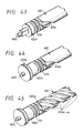
- Fig. 43 to Fig. 45 are perspective views showing three other embodiments of the lead screw 2.
- the whole of the lead screw is formed by use of a metallic material, and only the lead groove 402a is formed around the whole circumference thereof.
- the shaft 402c At the ends of the lead screw are provided the shaft 402c and the boss.
- the boss portion 402A worked by use of a plastic material.
- the boss portion 402A has a lead groove 456 communicated to the lead groove 402a formed by molding.
- the transmission gear 403A not shown.
- Fig. 45 bulk production and reduction in cost are effected by facilitating preparation of the lead screw 402 as described in Fig. 41, and the lead groove 402a is not a single thread, but lead grooves 402al-a4 of multiple threads are formed according to the rolling system.
- the engagement with the driving pin is a single thread
- the driving pin will come into other lead grooves 201A during reversal in direction of rotation, whereby registration slippage occurs.
- a regulating member 402gl which blocks other lead grooves except for a single thread is interposed between the lead grooves 402a2-a4 and the lead groove 456.
- the pitches of the lead groove of the lead screw for carriage driving are made different with the pitch in the recording region being made rough, while the pitch fine at the home position, superfluous movement of the carriage is obviated to enable capping under low load state. Also, by use of a lead screw, the positional precision between the recording head and capping can be made higher, whereby sure capping can be effected.
- the lead screw since the lead groove portion at the home position is assembled by forming it on a separate part from the main body of the lead screw, the lead screw can be easily manufactured.
- the lead screw rockable at the home position rocks the transmission gear mounted at its end to transmit the rotational force to the capping mechanism side, thereby effecting capping the cap over the head surface. Therefore, the gear change-over can be done with the minimum number of gears.
- the cap unit 4241 including the cap lever 424 has integrally the spring portion 424b, the mounting portion 4251 fitted to the shaft 425, as described above.
- the cap is required to be strongly pressed against the head surface. For this reason, the high torque type must be used for the motor for driving, whereby the consumption power was greater. Also, since the cap by use of a rubber was compressed, the volume of the cap closed space was reduced to become under pressurized state and bring about retreat of the meniscus within the nozzle, whereby defective discharging was generated.
- An object of this embodiment is to provide a small scale and inexpensive ink jet recording apparatus which can improve adhesivity between the head surface and the cap, and also accomplishes small power consumption.
- This embodiment has mounting members of the cap mounted on the movable member for moving the cap so as to be rockable upper and down, right and left, thereby enabling formation of the closed state stably and completely even when the discharge surface of the head may be slanted.
- the rib provided on the capping surface of the cap makes no air leak portion between the cap and the head, making adhesivity further complete. Therefore, even if mounting of the head may come out of the specification value or may be slanted by change with lapse of time, capping can be done while maintaining constantly good adhesivity.
- Fig. 46 is a perspective view showing the details of the cap unit comprising the cap lever 424 and the cap 426
- Fig. 47 an exploded perspective view showing details of the cap 426.
- the cap lever 424 is a cap lever as the movable member, which is mounted freely rotatably on the lever shaft 425 mounted on the intermediate side plate 400c of the base 40, and has the contact portion 4241a in contact with the cam 423a and the spring 424b for giving rotational force to the cap lever 424 integrally formed thereon. Further, the cap lever 424 has the hook portion 4241c for mounting on the cap holder 4242, the guide portion 4241d, and the semispherical type R-shaped projection 4241e integrally formed thereon. In this embodiment, the cap lever 424 is worked by use of a plastic material having elasticity such as polyacetal, etc., but this is not limitative, but any material may be available, provided that it exhibits similar chracteristics.
- a cap holder 4242 shown in Fig. 47 is a cap holder made of a metal, having the mounting portion 4242a for mounting on the cap lever 424 formed integrally thereon.
- the mounting portion 4242a is fitted freely within the space formed by the hook portion 4241c and the guide portion 4241d so that the cap holder 4242 as a whole can be oscillated in all the directions such as up and down, right and left, obliquely, etc. With such a constitution, adhesivity between the head and the cap can be improved.
- the hook portion 4243a On the back surface of the cap 426 is formed integrally the hook portion 4243a to be fitted into the cap holder 4242. Also, on the front surface of the cap 426 is formed a rib 427 as the cap member 427 (its height is set to the extent that the cap member does not contact the discharge port of the head 412) for improving adhesivity with the head 12.
- the rib 427 comprises a member enriched in flexibility, for example, a rubber material, etc. And, by making its height to the extent that the cap member does not contact the discharge port of the head 1412, the surface area within the cap can be made smaller to prevent solidification by drying of the ink on account of gas permeability of the rib 427.
- Fig.49 is a sectional view showing the details of another example of the cap unit.
- this cap lever 424 is that the mounting portion 4242a of the cap holder 4241 is formed spherical, and also the hook portion 4241c of the cap lever 424 is formed in R-shape, so that predetermined plays may be created right and left, up and down between the cap holder 4241 and the hook portion 4241c. Even with such a constitution, the same effect as in the constitution of the cap lever 424 in Fig. 46 as described above can be obtained.
- the mounting members of the cap are mounted on the movable member for moving the cap so as to be rockable in all the directions such as up and down, right and left, obliquely, etc.
- only a small head pressing force can be used to alleviate the power consumed of the driving system.
- the recording head will not come off from the position during capping, whereby positional precision can be exhibited with ease.
- Ths constitution is characterized by provision of a transmission means for transmitting the driving force generated by the motor which generates the driving force for moving the carrier to the carrier, a supporting means which supports the motor rockably and an urging means which effects engagement between the motor and the transmission means by urging in a predetermined direction of rocking.
- a motor mounting hole is provided on the chassi 400 for supporting the carrier motor rotatably.
- Fig. 50 shows the application of the rocking mechanism to the mounting method of the carrier motor 11 shown in Fig. 11.
- 50 is an elastic member comprising a rubber, etc., which has a hole at the center into which the rotatory pin 11a of the carrier motor is to be inserted.
- the rotatory pin 11a is mounted freely rotatably through the elastic member 50 in the motor mounting hole of the chassi 1, and therefore the carrier motor 11 becomes rotatable with the rotatory pin 11a as the rotation shaft.
- Fig. 51 shows another embodiment with a constitution which provides a timing belt 13 by spanning by urging the carrier motor 11 in a predetermined direction.
- 51 is a dumper having a gas or an oil sealed therein, of which one end of the two relatively movable portions is mounted on the spring receptacle 11b, while the other end is mounted on one end of the lead arm lh and inserted into the spring 14.
- Figs. 52A and 52B show another embodiment of the positional relationships between the lead screw 2 and the carrier motor 11.
- the positional relationship is constituted such that the rotational center of the carrier motor 11 is positioned on the line of 45° from vertically downward of the rotational center of the lead screw 2.
- Fig. 53 shows still another embodiment of the embodiment shown in Fig. 52.
- 52 is a balancer mounted with an arm on the carrier motor 11. With such a constitution, the difference in force acting on the belt 13 can be absorbed to make the force constant by the weight of the motor due to the posture difference of the apparatus as described above, whereby it becomes possible to give a degree of freedom in the arrangement of the motor 11 and the lead screw 2.
- the spring 14 for acting finally a predetermined tension on the belt 13 is not required to have a great elastic force which can correspond to all the posture changes of the apparatus.
- the constitution of the carrier mediating driving force as described above in the present embodiment is not limited to the lead screw driving system, but also applicble to wire, belt, etc., as a matter of course.
- Figs. 54 to 57 show an embodiment in which the pressure change within the cap member which occurs by covering of the cap member over the discharge port surface in the capping actuation is made so as to have no influence on the meniscus within the discharge port even under various bad conditions, which embodiment is characterized in that an adhering member is equipped, which forms a space including the space near the discharge port hermetically closed with the above-mentioned covering actuation, with its internal invariable pressure with the above-mentioned covering actutaion, as accompanied with the covering actuation of the cap member as mentioned above.
- the adhering pad 350 is an adhering pad mounted on the closed cap 35a which contacts the discharge port surface of the recording head during capping, and is formed of a foamed urethane foamed communicatingly.
- the surface of the adhering pad 350 which contacts the discharge port surface is formed a solid layer (skin film) 350a having the same difficult deformability as described above formed during molding of the foamed urethane, and ensures the sealing effect when adhered onto the discharge port surface.
- the adhering pad 350 is mounted onto the closed cap 35a by plastering the surface 350b on the opposite side to the surface where 350a is formed to the seat surface of the closed cap 35a with a double-side tape or an adhesive, etc.
- the solid layer 350a of the adhering pad 350 is adhered onto the discharge port forming surface 9d to contact the front seal plate 90a having an opening in the vicinity of the discharge port, and the space ⁇ V formed at the opening portion is closed by this contact.
- the equalizing function of the cap member as mentioned above is excellent, and even when there is a stepped difference at the discharge port forming surface, can maintain stable closed state by absorbing instantly the stepped difference.
- Fig. 56 is a side sectional view for illustration of the capping actuation according to still another embodiment of the present invention.
- the closed cap 35a of this embodiment has a concavity 35f with the same shape as the opening of the front seal plate 90a formed on the seat surface on which the adhering pad 350 is mounted.
- Fig. 57 is a side sectional view for illustration of the capping actuation according to still another embodiment of the capping constitution of the present invention.
- the solid layer 350a of this embodiment has its portion opposed to the discharge port 9c molded in a concave shape.
- the present invention is also applicable to the closed cap which is used together with the recording head having no front surface seal plate, and a predetermined space not affected in pressure change by the contact of the adhering pad 350 against the discharge port surface can be formed.
- FIG. 59 to Fig. 60 modified embodiments of the piston 28 to be applied to Figs. 9A and 9B are shown in Fig. 59 to Fig. 60.
- the piston 28 of the pump means having the effects of miniaturization and ink thickening prevention effect as described in Fig. A, B is made to have a constitution in which the annular contact portion, which blocks the route for discharging ink in the actutation according to suction through contact, and forms the route for said discharging in the actuation according to discharging through separation, is provided on either the end surface of the piston or the end surface of the pushing member which pushes the end surface in the suction actuation.
- 28c is a seal rib provided on one end surface 28b of the piston 28 concentrically with the same end surface, of which lateral cross-section is semispherical.
- the seal rib 28c is the site which contacts directly the piston presser 27b when the piston 28 and the piston presser 27b actuate with engagement, and its sealability becomes better through contact along a line as a whole, and also can be rapidly separated from the piston presser without influence from the viscosity of the ink.
- Fig. 59 is a perspective view of the piston showing another embodiment of the piston 28 of the present invention.
- a seal rib 28f is provided at the peripheral portion thereof. In this way, sealability in valve action during ink suction is improved.
- Fig. 60 is a side sectional view showing the engaged state of the piston presser and the piston according another embodiment of the piston 28 of the present invention. As shown in the same Figure, in this embodiment, an annular seal rib 27c is provided on the end surface of the piston presser 27b, and the end surface of the piston 28 is made flat.
- the rib 27c contacts the end surface of the piston 28 when the piston 28 is pushed through the piston presser 27b, the amount of the rib 2c bitten onto the end surface can be small, whereby the positional relationship during piston actuation can be stabilized.
- the recording head of the present invention may have the above-described structure wherein the flow passage is linear and the liquid is ejected in the direction from one edge of the heater to the other edge, in the structure where the liquid passage is bent at the position of the electrothermal transducer to eject the liquid in the direcion perpendicular to the surface of the electrothermal transducer element, or the structure wherein the passage is bent at an angle not 90 degrees as disclosed in U.S. Patents Nos. 4,558,333 and 4,459,600.
- the present inventon is applicable to the structure disclosed in a Japanese Laid-Open Patent Application 59-123670 wherein a common slit is formed to provide the ejecting portions relative to the plural electrothermal transducers or to the structures disclosed in Japanese Laid-open Patent Application 59-138461 wherein the pressure wave produced by the thermal energy is absorbed by an opening provided for the ejecting outlet.
- the present invention is also applicable to the recording substrate, recording head or the recording apparatus for multi- or full-color recording apparatus wherein plural recording heads are used in combination or as a unit.
Abstract
Description
Claims (11)
- An ink jet apparatus comprising a pump for generating a pressure change used for sucking ink from a discharge port for discharging ink through a cap for covering the discharge port, said pump having:a cylinder;a piston shaft reciprocally movable in said cylinder; anda cylindrical piston in said cylinder, reciprocally movable in said cylinder by contact with said piston shaft, for forming a closed suction chamber in said cylinder by closely contacting an inner wall of said cylinder and said piston shaft when said piston shaft moves from an upper dead center to a lower dead center of said cylinder,wherein said inner wall of said cylinder is in close contact with an outer wall of said piston and a sealing rib is provided on at least one of a close contact surface of said piston against said piston shaft and a close contact surface of said piston shaft against said piston, said sealing rib thereby providing close contact between said piston shaft and said piston when said piston shaft moves from the upper dead center to the lower dead center of said cylinder, and wherein said pressure change is generated in said suction chamber as said piston shaft moves from the upper dead center to the lower dead center of said cylinder, and the close contact between said piston shaft and said piston is released when said piston shaft moves from the lower dead center to the upper dead center, thereby opening a gap between said piston shaft and said piston, the gap forming a route for expelling waste ink sucked in said suction chamber.
- An ink jet apparatus according to claim 1, wherein said sealing rib is provided on an end surface of said piston concentrically with said end surface, and the cross-section of said rib is semicircular.
- A pump for an ink jet apparatus comprising a pump for generating a pressure change used for sucking ink from a discharge port for discharging ink through a cap for covering the discharge port, said pump having:a cylinder;a piston shaft reciprocally movable in said cylinder; anda cylindrical piston in said cylinder, reciprocally movable in said cylinder by contact with said piston shaft, for forming a closed suction chamber in said cylinder by closely contacting an inner wall of said cylinder and said piston shaft when said piston shaft moves from an upper dead center to a lower dead center of said cylinder,wherein said inner wall of said cylinder is in close contact with an outer wall of said piston and a sealing rib is provided on at least one of a close contact surface of said piston against said piston shaft and a close contact surface of said piston shaft against said piston, said sealing rib thereby providing close contact between said piston shaft and said piston when said piston shaft moves from the upper dead center to the lower dead center of said cylinder, and wherein said pressure change is generated in said suction chamber as said piston shaft moves from the upper dead center to the lower dead center of said cylinder, and the close contact between said piston shaft and said piston is released when said piston shaft moves from the lower dead center to the upper dead center, thereby opening a gap between said piston shaft and said piston, the gap forming a route for expelling waste ink sucked in said suction chamber.
- A pump for sucking ink from an ink discharge port of an ink jet head, said pump comprising:a cylinder;a piston shaft reciprocally movable in said cylinder; anda cylindrical piston movable in said cylinder with said piston shaft and forming with the cylinder a suction chamber,wherein a sealing rib is provided on at least one of said piston and said piston shaft and wherein movement of said piston shaft in one direction generates a suction force for sucking ink from an ink discharge port into the suction chamber and movement of the piston shaft in the opposite direction causes a gap to open between said piston shaft and said piston forming a route for expelling waste ink from said suction chamber.
- A pump according to claim 3 or 4, wherein said sealing rib is provided on an end surface of said piston concentrically with said end surface, and the cross-section of said rib is semicircular.
- An ink jet recording apparatus comprising a pump in accordance with claim 3, 4 or 5.
- An ink jet recording apparatus equipped with an ink suction pump which performs discharge recovery treatment for maintaining the ink within the discharge port under a predetermined state by sucking ink from the discharge port of a recording head,wherein said ink suction pump is an ink suction pump which has a cylinder and a piston moving in a reciprocal fashion relative to said cylinder therein and performs suction of said ink and discharge of said sucked ink as accompanied with said reciprocal movement,an annular contact portion forming a route for said discharge, which, in the actuation according said suction, blocks the route for discharging said ink, and maintains a predetermined interval by separation in the actuation according said discharge, is provided at either the end surface of said piston or the end surface of the pushing member which pushes said end surface in the actuation of said suction.
- An ink suction pump having a cylinder and a piston which moves in a reciprocal fashion relative to said cylinder therein, which performs suction of ink and discharge of said ink sucked,
wherein an annular contact portion forming a route for said discharge, which, in the actuation according said suction, blocks the route for discharging said ink, and maintains a predetermined interval by separation in the actuation according said discharge, is provided at either the end surface of said piston or the end surface of the pushing member which pushes said end surface in the actuation of said suction. - An ink jet recording apparatus according to claim 7 or an ink suction pump according to claim 8, wherein said annular contact portion is a rib provided on the end surface of said piston concentrically with said end surface, and the cross-section of said rib is semicircular.
- An ink jet recording apparatus according to claim 7 or an ink suction pump according to claim 8, wherein said annular contact portion is a rib provided on the end surface of said pushing member concentrically with said end surface, and the cross-section of said rib is semicircular.
- An ink jet apparatus according to claim 1, 6 or 7, wherein the ink is discharged from the discharge port by utilizing heat energy.
Priority Applications (1)
| Application Number | Priority Date | Filing Date | Title |
|---|---|---|---|
| EP00201508A EP1031424B1 (en) | 1988-12-21 | 1989-12-20 | An ink jet recording apparatus having a recovery mechanism |
Applications Claiming Priority (41)
| Application Number | Priority Date | Filing Date | Title |
|---|---|---|---|
| JP323011/88 | 1988-12-21 | ||
| JP32301188 | 1988-12-21 | ||
| JP32301188A JP2789341B2 (en) | 1988-12-21 | 1988-12-21 | Ink jet recording device |
| JP7289/89 | 1989-01-13 | ||
| JP729089 | 1989-01-13 | ||
| JP7288/89 | 1989-01-13 | ||
| JP1007290A JP2799720B2 (en) | 1989-01-13 | 1989-01-13 | Ink jet recording device |
| JP728889A JP2711876B2 (en) | 1989-01-13 | 1989-01-13 | Ink jet recording device |
| JP7290/89 | 1989-01-13 | ||
| JP897289A JPH02187360A (en) | 1989-01-13 | 1989-01-13 | Ink jet recording device |
| JP728989 | 1989-01-13 | ||
| JP728889 | 1989-01-13 | ||
| JP13496/89 | 1989-01-23 | ||
| JP13493/89 | 1989-01-23 | ||
| JP1013493A JP2705961B2 (en) | 1989-01-23 | 1989-01-23 | Ink jet recording device |
| JP13492/89 | 1989-01-23 | ||
| JP1013496A JPH02194971A (en) | 1989-01-23 | 1989-01-23 | Ink jet recorder |
| JP1349289 | 1989-01-23 | ||
| JP1349789A JP2705962B2 (en) | 1989-01-23 | 1989-01-23 | Ink jet recording device and recovery mechanism |
| JP1349589 | 1989-01-23 | ||
| JP1349489 | 1989-01-23 | ||
| JP1013494A JPH02194963A (en) | 1989-01-23 | 1989-01-23 | Ink jet recorder |
| JP1349689 | 1989-01-23 | ||
| JP1349389 | 1989-01-23 | ||
| JP1349789 | 1989-01-23 | ||
| JP1349289A JP2726076B2 (en) | 1989-01-23 | 1989-01-23 | Ink jet recording device |
| JP1013495A JP2792659B2 (en) | 1989-01-23 | 1989-01-23 | Ink jet recording device |
| JP13494/89 | 1989-01-23 | ||
| JP13495/89 | 1989-01-23 | ||
| JP13497/89 | 1989-01-23 | ||
| JP1047412A JP2731217B2 (en) | 1989-02-28 | 1989-02-28 | Recording device |
| JP4741289 | 1989-02-28 | ||
| JP47412/89 | 1989-02-28 | ||
| JP13930989 | 1989-06-02 | ||
| JP13931989A JP2693229B2 (en) | 1989-06-02 | 1989-06-02 | Inkjet recording device and ink suction pump |
| JP13931989 | 1989-06-02 | ||
| JP139309/89 | 1989-06-02 | ||
| JP1139309A JPH035153A (en) | 1989-06-02 | 1989-06-02 | Ink jet recorder |
| JP139319/89 | 1989-06-02 | ||
| EP93203141A EP0589541B1 (en) | 1988-12-21 | 1989-12-20 | Ink jet recording apparatus with printhead capping means |
| EP89313389A EP0375407B1 (en) | 1988-12-21 | 1989-12-20 | Recovery mechanism of an ink jet recording apparatus |
Related Parent Applications (1)
| Application Number | Title | Priority Date | Filing Date |
|---|---|---|---|
| EP93203141A Division EP0589541B1 (en) | 1988-12-21 | 1989-12-20 | Ink jet recording apparatus with printhead capping means |
Related Child Applications (1)
| Application Number | Title | Priority Date | Filing Date |
|---|---|---|---|
| EP00201508A Division EP1031424B1 (en) | 1988-12-21 | 1989-12-20 | An ink jet recording apparatus having a recovery mechanism |
Publications (3)
| Publication Number | Publication Date |
|---|---|
| EP0854041A2 true EP0854041A2 (en) | 1998-07-22 |
| EP0854041A3 EP0854041A3 (en) | 1998-09-09 |
| EP0854041B1 EP0854041B1 (en) | 2002-05-22 |
Family
ID=27584113
Family Applications (4)
| Application Number | Title | Priority Date | Filing Date |
|---|---|---|---|
| EP93203141A Expired - Lifetime EP0589541B1 (en) | 1988-12-21 | 1989-12-20 | Ink jet recording apparatus with printhead capping means |
| EP89313389A Expired - Lifetime EP0375407B1 (en) | 1988-12-21 | 1989-12-20 | Recovery mechanism of an ink jet recording apparatus |
| EP00201508A Expired - Lifetime EP1031424B1 (en) | 1988-12-21 | 1989-12-20 | An ink jet recording apparatus having a recovery mechanism |
| EP98200721A Expired - Lifetime EP0854041B1 (en) | 1988-12-21 | 1989-12-20 | Pump for an ink jet recording apparatus |
Family Applications Before (3)
| Application Number | Title | Priority Date | Filing Date |
|---|---|---|---|
| EP93203141A Expired - Lifetime EP0589541B1 (en) | 1988-12-21 | 1989-12-20 | Ink jet recording apparatus with printhead capping means |
| EP89313389A Expired - Lifetime EP0375407B1 (en) | 1988-12-21 | 1989-12-20 | Recovery mechanism of an ink jet recording apparatus |
| EP00201508A Expired - Lifetime EP1031424B1 (en) | 1988-12-21 | 1989-12-20 | An ink jet recording apparatus having a recovery mechanism |
Country Status (5)
| Country | Link |
|---|---|
| US (2) | US5757397A (en) |
| EP (4) | EP0589541B1 (en) |
| KR (1) | KR940010882B1 (en) |
| DE (2) | DE68928854T2 (en) |
| ES (1) | ES2073447T3 (en) |
Families Citing this family (28)
| Publication number | Priority date | Publication date | Assignee | Title |
|---|---|---|---|---|
| US5168291A (en) * | 1989-04-24 | 1992-12-01 | Canon Kabushiki Kaisha | Recording apparatus and ink cassette therefor |
| JPH041056A (en) * | 1990-04-19 | 1992-01-06 | Canon Inc | Ink-jet recording device |
| DE69126900T2 (en) * | 1990-02-28 | 1998-02-12 | Canon Kk | Inkjet device |
| EP0449324B1 (en) * | 1990-03-30 | 1997-06-25 | Canon Kabushiki Kaisha | Ink jet recording apparatus and pump mechanism for use therewith |
| ATE140426T1 (en) * | 1990-09-19 | 1996-08-15 | Canon Kk | RECOVERY DEVICE FOR A COLOR RAY RECORDING APPARATUS |
| DE69219180T2 (en) * | 1991-02-12 | 1997-10-02 | Canon Kk | Ink jet recording system and method |
| EP0540344B1 (en) * | 1991-10-31 | 1999-01-20 | Canon Kabushiki Kaisha | Recovery mechanism and an ink jet recording apparatus using the recovery mechanism |
| US5325111A (en) * | 1992-12-28 | 1994-06-28 | Xerox Corporation | Removing waste ink from capping station |
| JP3262410B2 (en) * | 1993-06-21 | 2002-03-04 | キヤノン株式会社 | Ink jet recording device |
| JP3129099B2 (en) * | 1994-09-09 | 2001-01-29 | ブラザー工業株式会社 | Pump with drive |
| NL9401941A (en) * | 1994-11-21 | 1996-07-01 | Techniku B V | Device for cleaning and sealing a print head, a printing device provided with such a device, and a method for applying it. |
| JP3209075B2 (en) | 1996-02-26 | 2001-09-17 | ブラザー工業株式会社 | Inkjet printer |
| AU1533497A (en) * | 1996-08-15 | 1998-03-06 | Minnesota Mining And Manufacturing Company | Service station for ink jet printers |
| US5956053A (en) * | 1996-10-31 | 1999-09-21 | Hewlett-Packard Company | Dual seal capping system for inkjet printheads |
| AU745867B2 (en) * | 1997-11-26 | 2002-04-11 | Syngenta Participations Ag | Method and compositions useful for the activation of silent transgenes |
| AUPP702498A0 (en) * | 1998-11-09 | 1998-12-03 | Silverbrook Research Pty Ltd | Image creation method and apparatus (ART77) |
| US6249300B1 (en) * | 1999-07-15 | 2001-06-19 | Eastman Kodak Company | Method and apparatus for positioning a writing assembly of an image processing apparatus |
| US6520618B2 (en) * | 2000-02-24 | 2003-02-18 | Canon Kabushiki Kaisha | Pump, device for recovering liquid ejection and image forming apparatus equipped with the pump |
| US6769763B2 (en) * | 2000-09-12 | 2004-08-03 | Canon Kabushiki Kaisha | Cylinder pump, an ink jet printing system using the cylinder pump and a photograph assembly having the printing system |
| JP2004230843A (en) * | 2003-01-31 | 2004-08-19 | Canon Inc | Inkjet recording device |
| JP3925480B2 (en) * | 2003-09-25 | 2007-06-06 | ブラザー工業株式会社 | Inkjet printer, inkjet printer control method, pump control method |
| TWI232801B (en) | 2004-04-08 | 2005-05-21 | Int United Technology Co Ltd | Printhead controller and ink jen printer |
| US7661810B2 (en) * | 2005-03-02 | 2010-02-16 | Fujifilm Corporation | Image recording apparatus and inkjet apparatus for double-side recording |
| WO2011136788A1 (en) * | 2010-04-30 | 2011-11-03 | Hewlett-Packard Development Company, L.P. | Capping for inkjet printers |
| JP5860257B2 (en) * | 2011-09-29 | 2016-02-16 | 株式会社Screenホールディングス | Inkjet printing device |
| JP5861474B2 (en) | 2012-01-30 | 2016-02-16 | セイコーエプソン株式会社 | Pump device |
| JP2018096468A (en) * | 2016-12-14 | 2018-06-21 | キヤノン株式会社 | Drive device and imaging device |
| JP6828422B2 (en) * | 2016-12-22 | 2021-02-10 | セイコーエプソン株式会社 | Liquid injection device and cleaning device |
Citations (4)
| Publication number | Priority date | Publication date | Assignee | Title |
|---|---|---|---|---|
| US4383263A (en) * | 1980-05-20 | 1983-05-10 | Canon Kabushiki Kaisha | Liquid ejecting apparatus having a suction mechanism |
| US4410900A (en) * | 1979-10-23 | 1983-10-18 | Canon Kabushiki Kaisha | Ink jet recording apparatus |
| US4631554A (en) * | 1982-10-04 | 1986-12-23 | Canon Kabushiki Kaisha | Ink jet printing apparatus with suction recovery unit |
| EP0286841A2 (en) * | 1987-03-13 | 1988-10-19 | Canon Kabushiki Kaisha | Recovery device for ink-jet recording apparatus and ink-jet recording apparatus having the same |
Family Cites Families (36)
| Publication number | Priority date | Publication date | Assignee | Title |
|---|---|---|---|---|
| US1674735A (en) * | 1927-10-24 | 1928-06-26 | Holland Furnace Co | Warm-air furnace |
| US2185215A (en) * | 1934-05-01 | 1940-01-02 | Apex Electrical Mfg Co | Motor mounting |
| US2791126A (en) * | 1953-07-06 | 1957-05-07 | Daniel E Christopher | Motor base |
| US3558244A (en) * | 1968-09-03 | 1971-01-26 | Maruyama Mfg Co | High pressure pump |
| US3628645A (en) * | 1969-10-23 | 1971-12-21 | Ncr Co | Carriage drive mechanism |
| US3652188A (en) * | 1970-06-01 | 1972-03-28 | Maruyama Mfg Co | High pressure pump |
| US3809508A (en) * | 1971-12-06 | 1974-05-07 | Maruyama Mfg Co | Pump |
| US3913460A (en) * | 1972-08-10 | 1975-10-21 | Mosier Ind Inc | Impact damping means for fluid cylinders |
| US3920356A (en) * | 1973-04-02 | 1975-11-18 | Cat Pumps Corp | Reciprocating pump |
| US3930756A (en) * | 1974-01-14 | 1976-01-06 | Cat Pumps Corporation | Metering pulse pump |
| US3957150A (en) * | 1975-01-08 | 1976-05-18 | Scm Corporation | Impression control apparatus for typewriters |
| DE2705328C3 (en) * | 1977-02-09 | 1981-02-12 | Olympia Werke Ag, 2940 Wilhelmshaven | Covering device for covering the nozzles in an ink pen |
| GB1552268A (en) * | 1977-04-01 | 1979-09-12 | Standard Telephones Cables Ltd | Semiconductor etching |
| US4306245A (en) * | 1978-09-21 | 1981-12-15 | Canon Kabushiki Kaisha | Liquid jet device with cleaning protective means |
| US4330787A (en) | 1978-10-31 | 1982-05-18 | Canon Kabushiki Kaisha | Liquid jet recording device |
| US4558333A (en) | 1981-07-09 | 1985-12-10 | Canon Kabushiki Kaisha | Liquid jet recording head |
| GB2112715B (en) * | 1981-09-30 | 1985-07-31 | Shinshu Seiki Kk | Ink jet recording apparatus |
| CA1195178A (en) * | 1981-10-08 | 1985-10-15 | Koji Terasawa | Capping device for a multi-ink jet head |
| JPS5862057A (en) * | 1981-10-08 | 1983-04-13 | Canon Inc | Capping device of ink jet nozzle |
| US4510510A (en) * | 1982-04-13 | 1985-04-09 | Canon Kabushiki Kaisha | Inkjet printer |
| JPS58177368A (en) * | 1982-04-13 | 1983-10-18 | Canon Inc | Sucking device of multinozzle head |
| US4533927A (en) * | 1982-05-06 | 1985-08-06 | Sharp Kabushiki Kaisha | Capping mechanism for preventing nozzle blocking in an ink jet system printer |
| JPS5914964A (en) | 1982-07-15 | 1984-01-25 | Seiko Epson Corp | Inkjet printer |
| JPS5945161A (en) | 1982-09-08 | 1984-03-13 | Seiko Epson Corp | Capping of nozzle of ink jet printer |
| JPS59123670A (en) | 1982-12-28 | 1984-07-17 | Canon Inc | Ink jet head |
| JPS59138461A (en) | 1983-01-28 | 1984-08-08 | Canon Inc | Liquid jet recording apparatus |
| US4631556A (en) * | 1983-05-11 | 1986-12-23 | Canon Kabushiki Kaisha | Liquid jet recording apparatus |
| JPS60104336A (en) * | 1983-11-11 | 1985-06-08 | Ricoh Co Ltd | Ink suction and discharge apparatus of recording head in ink jet printer |
| US4494887A (en) * | 1984-01-10 | 1985-01-22 | Litton Systems, Inc. | High speed printer assembly |
| JPH089231B2 (en) * | 1984-01-31 | 1996-01-31 | キヤノン株式会社 | Discharge recovery method |
| US4746938A (en) * | 1985-07-11 | 1988-05-24 | Matsushita Electric Industrial Co. Ltd. | Ink jet recording apparatus with head washing device |
| JPH085185B2 (en) * | 1985-08-09 | 1996-01-24 | キヤノン株式会社 | Ink jet recording device |
| JPS6381048A (en) * | 1986-09-25 | 1988-04-11 | Alps Electric Co Ltd | Cap mechanism of ink jet head |
| GB2203994B (en) * | 1987-03-31 | 1991-12-11 | Canon Kk | Liquid injection recording apparatus and liquid-repellent process method used for the apparatus |
| DE3713794A1 (en) * | 1987-04-24 | 1988-11-10 | Siemens Ag | DEVICE FOR CLEANING AND SEALING THE NOZZLE SURFACE OF AN INK HEAD |
| US5067882A (en) * | 1990-06-20 | 1991-11-26 | Nordson Corporation | Dual-acting, reciprocating piston pump |
-
1989
- 1989-12-20 EP EP93203141A patent/EP0589541B1/en not_active Expired - Lifetime
- 1989-12-20 EP EP89313389A patent/EP0375407B1/en not_active Expired - Lifetime
- 1989-12-20 EP EP00201508A patent/EP1031424B1/en not_active Expired - Lifetime
- 1989-12-20 DE DE68928854T patent/DE68928854T2/en not_active Expired - Fee Related
- 1989-12-20 DE DE68923070T patent/DE68923070T2/en not_active Expired - Lifetime
- 1989-12-20 EP EP98200721A patent/EP0854041B1/en not_active Expired - Lifetime
- 1989-12-20 ES ES89313389T patent/ES2073447T3/en not_active Expired - Lifetime
- 1989-12-21 KR KR1019890019137A patent/KR940010882B1/en not_active IP Right Cessation
-
1993
- 1993-05-03 US US08/055,757 patent/US5757397A/en not_active Expired - Lifetime
-
1995
- 1995-06-06 US US08/466,780 patent/US6019452A/en not_active Expired - Lifetime
Patent Citations (4)
| Publication number | Priority date | Publication date | Assignee | Title |
|---|---|---|---|---|
| US4410900A (en) * | 1979-10-23 | 1983-10-18 | Canon Kabushiki Kaisha | Ink jet recording apparatus |
| US4383263A (en) * | 1980-05-20 | 1983-05-10 | Canon Kabushiki Kaisha | Liquid ejecting apparatus having a suction mechanism |
| US4631554A (en) * | 1982-10-04 | 1986-12-23 | Canon Kabushiki Kaisha | Ink jet printing apparatus with suction recovery unit |
| EP0286841A2 (en) * | 1987-03-13 | 1988-10-19 | Canon Kabushiki Kaisha | Recovery device for ink-jet recording apparatus and ink-jet recording apparatus having the same |
Also Published As
| Publication number | Publication date |
|---|---|
| DE68923070T2 (en) | 1995-11-16 |
| EP0375407A2 (en) | 1990-06-27 |
| EP0589541A1 (en) | 1994-03-30 |
| EP0854041B1 (en) | 2002-05-22 |
| KR900009288A (en) | 1990-07-04 |
| ES2073447T3 (en) | 1995-08-16 |
| EP0854041A3 (en) | 1998-09-09 |
| EP1031424B1 (en) | 2005-03-02 |
| EP1031424A3 (en) | 2000-12-06 |
| KR940010882B1 (en) | 1994-11-19 |
| EP0375407B1 (en) | 1995-06-14 |
| EP1031424A2 (en) | 2000-08-30 |
| EP0375407A3 (en) | 1991-07-03 |
| US5757397A (en) | 1998-05-26 |
| DE68923070D1 (en) | 1995-07-20 |
| US6019452A (en) | 2000-02-01 |
| DE68928854T2 (en) | 1999-05-12 |
| EP0589541B1 (en) | 1998-11-18 |
| DE68928854D1 (en) | 1998-12-24 |
Similar Documents
| Publication | Publication Date | Title |
|---|---|---|
| EP0375407B1 (en) | Recovery mechanism of an ink jet recording apparatus | |
| US5689293A (en) | Ink jet head capping device | |
| US5883645A (en) | Recovery mechanism and an ink jet recording apparatus using the recovery mechanism | |
| CN1165430C (en) | Lid pressing mechanism and ink jet recorder therewith | |
| JP2002036601A (en) | Recovery unit and ink jet recorder comprising it | |
| JP4661394B2 (en) | Liquid ejector | |
| JP2840409B2 (en) | Ink jet recording head and ink jet recording apparatus | |
| JP2792659B2 (en) | Ink jet recording device | |
| JP2726076B2 (en) | Ink jet recording device | |
| JP5170158B2 (en) | Liquid ejecting apparatus and liquid wiping apparatus | |
| JP2002301831A (en) | Ink-jet recorder | |
| JP2693229B2 (en) | Inkjet recording device and ink suction pump | |
| JP4479718B2 (en) | Rotating body, drive conversion device, cleaning device, and ink jet printer | |
| JP4687274B2 (en) | Liquid ejecting apparatus and liquid wiping apparatus | |
| JP2705962B2 (en) | Ink jet recording device and recovery mechanism | |
| JPH02194971A (en) | Ink jet recorder | |
| JP4158614B2 (en) | Rotating body, drive conversion device, cleaning device, and liquid ejecting device | |
| JP2705961B2 (en) | Ink jet recording device | |
| JP3832272B2 (en) | Head ejection characteristic maintaining device and ink jet printer having the same | |
| JP2848460B2 (en) | Recording device | |
| JPH02194963A (en) | Ink jet recorder | |
| JP2731217B2 (en) | Recording device | |
| JP2633963B2 (en) | Ink jet recording device | |
| JPH03293156A (en) | Ink jet recording apparatus and pump | |
| JPH03101968A (en) | Ink jet recorder |
Legal Events
| Date | Code | Title | Description |
|---|---|---|---|
| PUAI | Public reference made under article 153(3) epc to a published international application that has entered the european phase |
Free format text: ORIGINAL CODE: 0009012 |
|
| AC | Divisional application: reference to earlier application |
Ref document number: 589541 Country of ref document: EP |
|
| AK | Designated contracting states |
Kind code of ref document: A2 Designated state(s): DE ES FR GB IT NL |
|
| PUAL | Search report despatched |
Free format text: ORIGINAL CODE: 0009013 |
|
| AK | Designated contracting states |
Kind code of ref document: A3 Designated state(s): DE ES FR GB IT NL |
|
| 17P | Request for examination filed |
Effective date: 19990120 |
|
| 17Q | First examination report despatched |
Effective date: 19991019 |
|
| RTI1 | Title (correction) |
Free format text: PUMP FOR AN INK JET RECORDING APPARATUS |
|
| GRAG | Despatch of communication of intention to grant |
Free format text: ORIGINAL CODE: EPIDOS AGRA |
|
| GRAG | Despatch of communication of intention to grant |
Free format text: ORIGINAL CODE: EPIDOS AGRA |
|
| GRAG | Despatch of communication of intention to grant |
Free format text: ORIGINAL CODE: EPIDOS AGRA |
|
| GRAH | Despatch of communication of intention to grant a patent |
Free format text: ORIGINAL CODE: EPIDOS IGRA |
|
| GRAH | Despatch of communication of intention to grant a patent |
Free format text: ORIGINAL CODE: EPIDOS IGRA |
|
| GRAA | (expected) grant |
Free format text: ORIGINAL CODE: 0009210 |
|
| AC | Divisional application: reference to earlier application |
Ref document number: 589541 Country of ref document: EP Ref document number: 375407 Country of ref document: EP |
|
| PG25 | Lapsed in a contracting state [announced via postgrant information from national office to epo] |
Ref country code: NL Free format text: LAPSE BECAUSE OF FAILURE TO SUBMIT A TRANSLATION OF THE DESCRIPTION OR TO PAY THE FEE WITHIN THE PRESCRIBED TIME-LIMIT Effective date: 20020522 |
|
| REG | Reference to a national code |
Ref country code: GB Ref legal event code: FG4D |
|
| REF | Corresponds to: |
Ref document number: 68929403 Country of ref document: DE Date of ref document: 20020627 |
|
| NLV1 | Nl: lapsed or annulled due to failure to fulfill the requirements of art. 29p and 29m of the patents act | ||
| ET | Fr: translation filed | ||
| PG25 | Lapsed in a contracting state [announced via postgrant information from national office to epo] |
Ref country code: ES Free format text: LAPSE BECAUSE OF FAILURE TO SUBMIT A TRANSLATION OF THE DESCRIPTION OR TO PAY THE FEE WITHIN THE PRESCRIBED TIME-LIMIT Effective date: 20021128 |
|
| PLBE | No opposition filed within time limit |
Free format text: ORIGINAL CODE: 0009261 |
|
| STAA | Information on the status of an ep patent application or granted ep patent |
Free format text: STATUS: NO OPPOSITION FILED WITHIN TIME LIMIT |
|
| 26N | No opposition filed |
Effective date: 20030225 |
|
| PGFP | Annual fee paid to national office [announced via postgrant information from national office to epo] |
Ref country code: IT Payment date: 20071218 Year of fee payment: 19 |
|
| PGFP | Annual fee paid to national office [announced via postgrant information from national office to epo] |
Ref country code: GB Payment date: 20071228 Year of fee payment: 19 |
|
| PGFP | Annual fee paid to national office [announced via postgrant information from national office to epo] |
Ref country code: DE Payment date: 20071231 Year of fee payment: 19 |
|
| PGFP | Annual fee paid to national office [announced via postgrant information from national office to epo] |
Ref country code: FR Payment date: 20071220 Year of fee payment: 19 |
|
| GBPC | Gb: european patent ceased through non-payment of renewal fee |
Effective date: 20081220 |
|
| REG | Reference to a national code |
Ref country code: FR Ref legal event code: ST Effective date: 20090831 |
|
| PG25 | Lapsed in a contracting state [announced via postgrant information from national office to epo] |
Ref country code: DE Free format text: LAPSE BECAUSE OF NON-PAYMENT OF DUE FEES Effective date: 20090701 |
|
| PG25 | Lapsed in a contracting state [announced via postgrant information from national office to epo] |
Ref country code: GB Free format text: LAPSE BECAUSE OF NON-PAYMENT OF DUE FEES Effective date: 20081220 |
|
| PG25 | Lapsed in a contracting state [announced via postgrant information from national office to epo] |
Ref country code: FR Free format text: LAPSE BECAUSE OF NON-PAYMENT OF DUE FEES Effective date: 20081231 |
|
| PG25 | Lapsed in a contracting state [announced via postgrant information from national office to epo] |
Ref country code: IT Free format text: LAPSE BECAUSE OF NON-PAYMENT OF DUE FEES Effective date: 20081220 |