EP0854583A1 - Portable device battery technique - Google Patents
Portable device battery technique Download PDFInfo
- Publication number
- EP0854583A1 EP0854583A1 EP98300055A EP98300055A EP0854583A1 EP 0854583 A1 EP0854583 A1 EP 0854583A1 EP 98300055 A EP98300055 A EP 98300055A EP 98300055 A EP98300055 A EP 98300055A EP 0854583 A1 EP0854583 A1 EP 0854583A1
- Authority
- EP
- European Patent Office
- Prior art keywords
- battery
- power
- time
- user
- predetermined
- Prior art date
- Legal status (The legal status is an assumption and is not a legal conclusion. Google has not performed a legal analysis and makes no representation as to the accuracy of the status listed.)
- Granted
Links
Images


Classifications
-
- H—ELECTRICITY
- H02—GENERATION; CONVERSION OR DISTRIBUTION OF ELECTRIC POWER
- H02J—CIRCUIT ARRANGEMENTS OR SYSTEMS FOR SUPPLYING OR DISTRIBUTING ELECTRIC POWER; SYSTEMS FOR STORING ELECTRIC ENERGY
- H02J7/00—Circuit arrangements for charging or depolarising batteries or for supplying loads from batteries
- H02J7/0029—Circuit arrangements for charging or depolarising batteries or for supplying loads from batteries with safety or protection devices or circuits
- H02J7/0031—Circuit arrangements for charging or depolarising batteries or for supplying loads from batteries with safety or protection devices or circuits using battery or load disconnect circuits
-
- G—PHYSICS
- G06—COMPUTING; CALCULATING OR COUNTING
- G06F—ELECTRIC DIGITAL DATA PROCESSING
- G06F1/00—Details not covered by groups G06F3/00 - G06F13/00 and G06F21/00
- G06F1/26—Power supply means, e.g. regulation thereof
- G06F1/30—Means for acting in the event of power-supply failure or interruption, e.g. power-supply fluctuations
-
- H—ELECTRICITY
- H04—ELECTRIC COMMUNICATION TECHNIQUE
- H04B—TRANSMISSION
- H04B1/00—Details of transmission systems, not covered by a single one of groups H04B3/00 - H04B13/00; Details of transmission systems not characterised by the medium used for transmission
- H04B1/06—Receivers
- H04B1/16—Circuits
- H04B1/1607—Supply circuits
- H04B1/1615—Switching on; Switching off, e.g. remotely
-
- H—ELECTRICITY
- H04—ELECTRIC COMMUNICATION TECHNIQUE
- H04W—WIRELESS COMMUNICATION NETWORKS
- H04W52/00—Power management, e.g. TPC [Transmission Power Control], power saving or power classes
- H04W52/02—Power saving arrangements
- H04W52/0209—Power saving arrangements in terminal devices
- H04W52/0261—Power saving arrangements in terminal devices managing power supply demand, e.g. depending on battery level
- H04W52/0264—Power saving arrangements in terminal devices managing power supply demand, e.g. depending on battery level by selectively disabling software applications
-
- Y—GENERAL TAGGING OF NEW TECHNOLOGICAL DEVELOPMENTS; GENERAL TAGGING OF CROSS-SECTIONAL TECHNOLOGIES SPANNING OVER SEVERAL SECTIONS OF THE IPC; TECHNICAL SUBJECTS COVERED BY FORMER USPC CROSS-REFERENCE ART COLLECTIONS [XRACs] AND DIGESTS
- Y02—TECHNOLOGIES OR APPLICATIONS FOR MITIGATION OR ADAPTATION AGAINST CLIMATE CHANGE
- Y02D—CLIMATE CHANGE MITIGATION TECHNOLOGIES IN INFORMATION AND COMMUNICATION TECHNOLOGIES [ICT], I.E. INFORMATION AND COMMUNICATION TECHNOLOGIES AIMING AT THE REDUCTION OF THEIR OWN ENERGY USE
- Y02D30/00—Reducing energy consumption in communication networks
- Y02D30/70—Reducing energy consumption in communication networks in wireless communication networks
Definitions
- This invention relates to the providing of battery power for portable devices, and more particularly, to the providing of battery power for portable communication devices.
- a well known problem in the art of battery powered portable communication devices is how to extend the usable battery life so that power will be available to meet the user's need to communicate when there will, or can, be a long time between recharges of the battery.
- One solution is to design better batteries to expand the battery capacity.
- Another approach is to reduce the power consumption requirements of the portable communication device, so that the available battery power is consumed at a slower rate, and thus, effectively, the battery lasts longer.
- typical portable devices such as mobile telephones
- This warning starts when the user is on a call and battery power for approximately only two minutes worth of operation remains. The tone continues thereafter until there remains no battery power to operate the portable communication device.
- the user Upon hearing the warning tone, the user typically completes his call in an orderly, albeit often somewhat hurriedly, fashion prior to the point at which the portable telephone involuntarily powers off for lack of available battery power. Nevertheless, by virtue of having completed the call, the user typically causes consumption of most of what had been the remaining two minutes of battery power.
- little or no battery power is left available for subsequent high priority calls that one might need to either originate, such as when one is stuck on the road due to automobile failure, or that one might need to receive, such as an important call from one's boss.
- One straightforward method of trying to ameliorate this situation is to begin providing the warning tone somewhat earlier, e.g., when there yet remains ten minutes of battery life.
- the psychology employed by users when the warning tone begins at this earlier, e.g., ten-minute, point in time is somewhat different than when the warning tone begins later, e.g., at the two-minute point as described above.
- the additional battery power is automatically held in reserve, and so it will be available for subsequent high priority calls.
- the portable communications device powers off at the projected time, as though it then had no remaining battery power, if the user continues in the conventional manner.
- any battery power indicator that displays remaining battery power provides the user with an artificially low power reading that indicates that the battery power will be completely depleted at the projected time, i.e., at the conclusion of the predetermined period for which the almost-out-of-power warning is supplied.
- the earlier given short-term almost-out-of-power warning appears to be a genuine almost-out-of-power warning just like that provided in the prior art as described above.
- the user may take an affirmative action, such as pressing a button on the portable communication device, e.g., one marked "reserve power", to make available the additional power remaining in the battery.
- an affirmative action such as pressing a button on the portable communication device, e.g., one marked "reserve power”
- the user is less likely to use up his last available battery power if he is forced to take an affirmative action to do so.
- any battery power indicator which had been displaying an artificially low indication is restored to an accurate indication.
- the almost-out-of-power warning is again given to the user.
- FIG. 1 shows an exemplary portable device embodying the principles of the invention.
- a user of the portable device is signaled for a short period prior to a projected time with a short-term almost-out-of-power warning that indicates that there remains in the battery of the portable device enough power to operate the portable device only until the projected time, notwithstanding that there actually remains in the battery sufficient power to operate the portable device for some additional time beyond the projected time, and 2) the portable device is powered off at the projected time unless the user takes affirmative action to invoke the remaining battery power, which is otherwise held in reserve until such action affirmative is taken.
- the portable communications device is hand held mobile telephone 101, which includes keypad 105 and display 103.
- Mobile telephone 101 may be, for example, a cellular telephone, a personal communication system (PCS) telephone, a conventional portable telephone which is linked to a base unit coupled to a wired line, or d) any similar device.
- mobile telephone 101 may be operated in one of two modes. In a conversation mode, mobile telephone 101 is used to establish connections and conduct conversations. In a standby mode, it is powered on but is simply waiting either to receive or initiate a telephone call. Greater power is required to operate mobile telephone 101 in the conversation mode than in the standby mode. Hence the conversation mode causes the battery power to be consumed more quickly than the standby mode.
- PCS personal communication system
- Keypad 105 includes certain special function keys, such as scroll keys 107 and 109, RESERVE key 111, DISPLAY key 113, and PWR key 115. As those of ordinary skill in the art will recognize, keypad 105 may also include various other miscellaneous keys for such functions as volume control, send, end, etc. However, for clarity and simplification purposes, such keys are not shown in FIG. 1.
- Display 103 may be used to display the current status of the battery charge.
- display 103 can show the amount of remaining standby time, i.e., the time available to operate mobile telephone 101 in the standby mode, and the amount of time available to operate mobile telephone 101 in the conversation mode.
- display 103 is a bar graph type of display.
- other types of displays e.g. a numeric or alphanumeric display which displays the number of remaining minutes or another code indicative of the remaining time, may be employed.
- a voice announcement of the same information may be supplied to the user.
- Display 103 need not be constantly active, since doing so would result in a faster drain of the battery. Accordingly, display 103 may be controlled so as to actively display information thereon only when, and only so long as, such information is believed to be required by the user. Additionally, DISPLAY key 113 may be used to manually control activation of the display. For example, when battery power information is desired by the user, the display may be activated by pressing DISPLAY key 113 and then using scroll keys 107 and 109 to scroll to the battery-related display.
- FIG. 2 shows a block diagram illustration of an exemplary circuit for implementing mobile telephone 101.
- the circuit includes a) microprocessor 201, b) energy management unit 205, c) battery module 209, d) read only memory (ROM) 211, e) telephone electronics 213, and f) alerter 215.
- Display 103, telephone electronics 213, and alerter 215 are connected to, and controlled by, microprocessor 201.
- Keypad 105 is also connected thereto.
- Microprocessor 201 may be a microprocessor, microcontroller or any other control type of device.
- Microprocessor 201 may contain memory, e.g., ROM or random access memory (RAM).
- memory e.g., ROM or random access memory (RAM).
- RAM random access memory
- microprocessor 201 contains RAM which is not shown, but no ROM. Those of ordinary skill in the art will be able to select and arrange combinations of RAM, ROM, and control functionality to meet the needs of any particular application.
- Telephone electronics 213 contains all the circuitry necessary to establish and conduct voice-based conversations.
- Alerter 215 provides alerting information, such as the arrival of a telephone call or the short-term almost-out-of-power warning of the present invention.
- Energy management unit 205 can perform various battery functions, such as 1) recharging and 2) monitoring the state of battery cells 207 in battery module 209. Such energy management units are known in the art. Note that as used herein the term “battery” includes all groups of battery cells which are combined to form the operating power source of a portable device such as mobile telephone 101.
- Microprocessor 201 is connected to energy management unit 205 by way of bus 203, and over such a connection microprocessor 201 can obtain from energy management unit 205 the amount of remaining charge in battery module 209.
- the information obtained from energy management unit 205 may be stored within microprocessor 201.
- the status of battery module 209 obtained from energy management unit 205 may then be used to compute either a remaining standby time or a remaining conversation time, as well as other points in time along the battery power consumption curve, using stored estimates of power consumption when operating in each of the standby or conversation modes, respectively. This computation may be similar to the "miles to empty" computation performed in an automobile where the gas gauge reading is used in conjunction with the average fuel efficiency to determine the number of miles available for driving with the current amount of fuel in the tank.
- the calculation of remaining battery time can be estimated dynamically if the rate of power consumption (or current drain with a fixed voltage) is known.
- the power consumption for the various operating modes of mobile telephone 101 can be measured and stored a priori, so that microprocessor 201 can perform the estimations.
- microprocessor 201 there may be stored in ROM 211 the necessary power consumption data for various operating modes, e.g., average power consumption data for the standby and conversation modes.
- the actual current drain on the battery in mobile telephone 101 can be determined and then stored in memory in mobile telephone 101.
- a "history" of the current drain for each operating mode in mobile telephone 101 can be developed so that microprocessor 201 can utilize this "history" to provide a dynamic estimate of the amount of remaining battery time for both standby and conversation modes.
- FIGs. 3-5 show detailed processes for operating mobile telephone 101 in accordance with the principles of the invention.
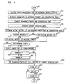
- FIG. 6 shows at a high level an example of the overall process carried out by mobile telephone 101 in practicing the invention.
- the short-term almost-out-of-power warning is started when there remains Y, e.g., ten, minutes worth of battery power in battery module 209.
- RESERVE key 111 Unless the user presses RESERVE key 111 within Z, e.g., two, minutes of the beginning of the warning mobile telephone 101 will power off at the end of those two minutes, in accordance with the principles of the invention. Thus, advantageously, eight minutes of battery power are held in reserve.
- step 601 The process of FIG. 6 is begun in step 601 when mobile telephone 101 is powered on, and then it may be repeated periodically.
- conditional branch point 603 tests to determine if there remains in battery module 209 enough power to power mobile telephone 101 for more than ten minutes in the current operating mode, e.g., conversation. If the test result in step 603 is YES, control passes to step 605, in which mobile telephone 101 is operated in the conventional manner, except that when battery information is displayed the remaining time is reduced by eight minutes. This is done so that the availability of the eight minutes worth of battery power is not shown to the user.
- step 603 If the test result in step 603 is NO, control passes to step 607, in which a two-minute warning is sounded. Also, operation of mobile telephone 101 and the display shown thereon are as previously described in step 605. In particular, when battery information is displayed, the remaining time is reduced by eight minutes. Advantageously, doing so psychologically reinforces to the user the genuineness of the two-minute warning, because the user sees on the display that he is nearly out of battery power.
- Control then passes to conditional branch point 609, which tests to determine if the user has pressed RESERVE key 111. If the test result in step 609 is NO, control passes to step 611. Conditional branch point 611 tests to determine if there remains in battery module 209 enough power to power mobile telephone 101 for more than eight minutes in the current operating mode. If the test result in step 611 is YES, control passes back to step 609. However, if the test result in step 611 is NO, this indicates that the only power remaining in battery module 209 is the reserve power. Therefore, control passes to step 613, in which, in accordance with an aspect of the invention, mobile telephone 101 powers off. By doing so, the reserve power is preserved for later usage on high priority telephone calls.
- step 609 If the test result in step 609 is YES, indicating that the user took the affirmative action of pressing RESERVE button 111 to make the reserve power available, control passes to step 615.
- step 615 mobile telephone 101 is enabled to operate until battery module 209 can no longer power it in the current operating mode. Also, when battery information is displayed, the true number of minutes remaining is displayed.
- FIG. 3 shows a process for updating the average usage parameters of mobile telephone 101 and for providing an estimate of the amount of current drain that occurs during standby and conversation modes.
- Such an average may be necessary for various reasons.
- the power consumption by mobile telephone 101 in each of the operating modes is not the same.
- the power consumption for identical mobile telephones of the same type as mobile telephone 101 need not be the same.
- mobile telephone 101 in each operating mode mobile telephone 101 must perform various functions that may each require different amounts of power, so that the power consumed during operation in a particular operating mode is not uniform.
- the process of FIG. 3 is an interrupt routine executed by microprocessor 201 (FIG. 2).
- microprocessor 201 determines the present operating mode i.e., conversation or standby, of mobile telephone 101. Thereafter, in step 305, microprocessor 201 determines the power consumed over the preceding interrupt period of time, e.g., by requesting from energy management unit 205 the amount of charge remaining in battery module 209 and subtracting it from the value which was obtained from energy management unit 205 in the immediately preceding iteration of step 205.
- the power consumption information determined by microprocessor 201 is stored in memory.
- the power consumption information is accumulated, in step 307, over a period of time equal to the sum of the lengths of a predetermined number, X, of interrupt periods.
- X is determined based upon the interrupt interval and the resolution of the power usage that is provided on display 103.
- microprocessor 201 determines an average power consumption. This may be a composite, i.e., a single current drain figure reflecting both standby and conversation modes, or separate average power consumptions may be determined for each of the conversation and standby modes of mobile telephone 101. In either case, the average is computed by taking the total accumulated power consumption and dividing it by the length of time equal to the sum of the lengths of X interrupt periods. The result is an average power consumption (or current drain) per unit time, which may be normalized to an average power consumption per one minute interval (milliamp/minute). The result may be stored in memory, preferably a non-volatile RAM, for use by the display routine.
- the resolution of display 103 in terms of the battery usage information, may be, for example, in units of minutes. Accordingly, with an interrupt interval of 100 milliseconds, microprocessor 201 would set X to a value of 600, so as to accumulate power consumption information over a total of 600 interrupt periods in order to provide the resolution of one minute of displayable battery usage information. When separate sums are kept for each operating mode, the number of interrupt periods that occur for each operating mode are counted separately. As such, X interrupt periods must be accumulated for each operating mode.
- the RAM-based variables are loaded with worst case-figures which were prestored in ROM 211. Accordingly, when a user of the mobile telephone 101 initially starts up the mobile telephone and requests a display of the battery information, the user will be provided with a worst-case scenario as to the remaining battery capacity. Such worst case figures are also used to initially determine the reserve power point and other time points which are described hereinbelow. Later, upon the acquiring of usage history through the above-discussed routine, the values displayed to the user and the other time points will be updated accordingly.
- FIG. 4 shows a process for supplying the short-term almost-out-of-power warning, in accordance with the principles of the invention.
- the process shown in FIG. 4 may be executed periodically by microprocessor 201, e.g., in response to an interrupt.
- microprocessor 201 accesses energy management unit 205 to obtain the available battery charge.
- microprocessor 201 retrieves the parameters necessary to determine the standby and conversation battery drain. That is, microprocessor 201 will access the average conversation drain and average standby battery drain parameters, such as those described hereinabove, which are stored in memory.
- step 407 the remaining standby and conversation times are computed.
- the available battery current e.g., milliamps
- the usage rate e.g., milliamps/minute
- the present operating mode of mobile telephone 101 is retrieved by microprocessor 201, which then determines, in step 411, the actual remaining battery life and a reserve power point, in accordance with an aspect of the invention.
- the reserve power point is the point in time at which the power in the battery will reach the level of power that is desired to keep in reserve, as per the invention.
- the actual remaining battery life and the reserve power point are computed based on the conversation mode. This is done to insure that when the short-term almost-out-of-power warning is generated there remains reserved battery life that can power mobile telephone 101 in the conversation mode, which draws greater power than the standby mode, and is the mode typically desired by the user.
- the actual value of the reserve power point is at the discretion of the implementor. It may be useful to set the reserve power point so as to keep reserved enough power to operate mobile telephone 101 in the conversation mode for between 5 and 10 minutes.
- microprocessor 201 tests to determine if the flag RESERVE_INVOKED is equal to "1". If the test result in step 413 is NO, indicating the user has not invoked the reserve power and that mobile telephone 101 is operating without the availability of any power beyond the reserve power point, control passes to step 415, in which a variable DIFF is set equal to the value of the actual remaining battery life in the present operating mode of mobile telephone 101 less the reserve power point as computed for the present operating mode of mobile telephone 101, in accordance with an aspect of the invention. Doing so effectively eliminates the availability of any power less than or equal to the reserve power point. Thereafter, control passes to step 419.
- step 413 If the test result in step 413 is YES, indicating the user has invoked the reserve power and that mobile telephone 101 may continue to operate beyond the reserve power point, even if it has not yet reached that point, control passes to step 417, in which the value of the variable DIFF is set equal to the value of the actual remaining battery life in the present operating mode of mobile telephone 101, in accordance with an aspect of the invention. Thereafter, control passes to step 419.
- Conditional branch point 419 tests to determine if the value of DIFF is less than or equal to a threshold value WARNING_POINT, which is the power value at which generation of the short-term almost-out-of-power warning is initiated. It is advantageous to determine the threshold value WARNING_POINT as a function of the present operating mode of mobile telephone 101 for each execution of conditional branch point 419. This is because, by doing so, one can set WARNING_POINT to a value appropriate for the present operating mode of mobile telephone 101, so that the short-term almost-out-of-power warning is given for the same period of time regardless of whether mobile telephone 101 is in the standby mode or in the conversation mode.
- test result in step 419 is YES, indicating that the apparent remaining power is less than the amount of power for triggering the supplying of short-term almost-out-of-power warning, and that therefore the warning must be supplied
- conditional branch point 433 tests to determine if the value of the flag NORMAL is equal to "1". When the flag NORMAL is set equal to "1" it indicates that mobile telephone 101 is operating with power greater than or equal to the reserve power point.
- step 433 If the test result in step 433 is NO, indicating that prior to this passage through step 419 mobile telephone 101 was operating with power greater than or equal to the reserve power point, control passes to step 435, which sets the value of NORMAL to "0". Doing so indicates that mobile telephone 101 is now operating with power less than the reserve power point. Control then passes to step 421. If the test result in step 433 is YES, indicating that prior to this passage through step 419 mobile telephone 101 was operating with power less than the reserve power point, control passes directly to step 421.
- step 421 the value of REMAINING_POWER is set equal to the value of DIFF converted to the present operating mode. It is the value of REMAINING_POWER that is displayed when the remaining battery life is displayed on display 103, in accordance with an aspect of the invention. For example, the value of REMAINING POWER is displayed whenever the mobile telephone is powered up or whenever the user presses DISPLAY key 113 (FIG. 1) and uses scroll keys 107 and 109 to scroll to the battery related display. The value of DIFF is then stored in step 423 (FIG. 4).
- conditional branch point 425 tests to determine if the value of DIFF is equal to zero. If the test result in step 425 is YES, this indicates either 1) when the reserve power has not yet been invoked, that the actual battery life has reached the reserve power point, and therefore, in accordance with an aspect of the invention, mobile telephone 101 must be powered off; or 2) the actual battery life has reached zero, in which case, also, mobile telephone 101 must be powered off. Therefore, control passes to step 427, in which mobile telephone 101 is powered off, and the process is then exited in step 429. If test result in step 425 is NO, indicating that mobile telephone 101 may continue to be operated, control passes directly to step 429, and the process is exited without powering off mobile telephone 101.
- FIG. 5 shows a process, in accordance with the principles of the invention, for determining the appropriate action for mobile telephone 101 to take when the PWR button of mobile telephone 101 is pressed.
- the process is used to power on or off mobile telephone 101 in response to presses of the PWR button, as well as to set necessary flags for further use by mobile telephone 101. Also, in the event that PWR and the RESERVE buttons are pressed simultaneously, the reserve power is made available so that mobile telephone 101 can be powered beyond the reserve power point.
- conditional branch point 505 tests to determine if the value of the flag NORMAL is equal to "0". When the flag NORMAL is set equal to "1" it indicates that mobile telephone 101 is operating with power greater than or equal to the reserve power point. If the test result in step 505 is YES, indicating that mobile telephone 101 is operating with power greater than or equal to the reserve power point, control passes to conditional branch point 507.
- Conditional branch point 507 tests to determine if mobile telephone 101 is currently powered off. If the test result in step 507 is YES, indicating that mobile telephone 101 is currently powered off, control passes to step 509, which powers on mobile telephone 101. Control then passes to step 511, which sets and stores the present operating mode of mobile telephone 101. Control then passes to the rest of the code for operating mobile telephone 101.
- test result in step 507 is NO, indicating that mobile telephone 101 is currently powered on and operating, control passes to step 521, and mobile telephone 101 is powered off. The process then exits in step 523.
- test result in step 505 is NO, indicating that mobile telephone 101 is operating with power less than the reserve power point
- control passes to conditional branch point 515, which tests to determine if the PWR and the RESERVE buttons were pressed simultaneously. If the test result in step 515 is YES, indicating that the user pressed both the PWR and the RESERVE buttons simultaneously, which is the action necessary to invoke the reserve power and thus make it available, control passes to step 517, in which the value of RESERVE_INVOKED is set equal to "1". Thereafter, or if the test result in step 515 is NO, which indicates that the reserve power was not invoked, control passes to step 519.
- Conditional branch point 519 tests to determine if the value of DIFF is equal to zero. If the test result in step 519 is YES, indicating either a) that the battery has reached the reserve power point and the reserve power has not yet been invoked or b) there actually is no remaining battery power, control passes to step 521, and mobile telephone 101 is powered off, in accordance with an aspect of the invention. The process then exits in step 523. If the test result in step 519 is YES, indicating that there remains in the battery power that is currently permitted to be used to power mobile telephone 101, control passes to step 507 and the process continues as described above.
- the techniques of the invention may be applied to other battery-operated devices which have multiple operating modes, such as lap top computers, e.g., active and sleep, where the user would like to know the amount of remaining operating time.
- lap top computers e.g., active and sleep
- the invention may be employed with electronic devices that only have a single operating mode.
- energy, power, current, and charge are all used to represent the ability of a battery to operate a device.
- the battery is considered depleted when it can no longer operate the portable device in an operating mode desired by the user.
- the battery may be considered depleted when it can no longer power a mobile telephone in the conversation mode, notwithstanding that the battery can power the mobile telephone in the standby mode.
Abstract
Description
Claims (16)
- A method for use in a portable device powered by a battery, comprising the steps of:at a point at which the battery is depleted to a predetermined power level, developing a signal which indicates that the battery will be completely depleted within a predetermined amount of time even though there actually remains sufficient power in the battery to power said portable device for a further period of time in addition to the predetermined amount of time; andpowering off said portable communications device upon the passing of the predetermined amount of time unless a user performs a predetermined action prior thereto.
- The invention as defined in claim 1 wherein said portable device has a battery power indicator, and further comprising the step of adjusting said battery power indicator to indicate that said battery will be completely depleted upon the expiration of the predetermined amount of time.
- The invention as defined in claim 2 further comprising the step of adjusting said battery power indicator to indicate the true battery power available in response to receipt of a signal indicating that the user performed the predetermined action.
- The invention as defined in claim 1 wherein said portable device is a communications device.
- The invention as defined in claim 1 wherein said developed signal is perceptible by the user.
- The invention as defined in claim 1 wherein said portable device has a battery power indicator, and further comprising the step of continually adjusting said battery power indicator so that at any time prior to executing the powering off step said battery power indicator indicates a false low reading which conveys that the power to power said portable device for a further period of time in addition to the predetermined amount of time does not exist within the battery.
- The invention as defined in claim 1 further comprising the steps of:receiving a signal in response to the user performing the predetermined action prior to expiration of the predetermined amount of time; andin response to the received signal, enabling said portable device to remain powered on beyond the expiration of the predetermined amount of time.
- The invention as defined in claim 1 further comprising the steps of:receiving a signal in response to the user performing the predetermined action prior to expiration of the predetermined amount of time; andin response to the received signal, enabling said portable device to remain powered on beyond the expiration of the predetermined amount of time until the battery is so depleted that said portable device cannot continue to operate in its then current mode of operation.
- The invention as defined in claim 1 further comprising the steps of:receiving a signal that the user performed the predetermined action prior to expiration of the predetermined amount of time;in response the received signal, enabling said portable device to remain powered on beyond the expiration of the predetermined amount of time; andconveying to a user a signal which indicates that the battery is nearly depleted at a point at which the battery is depleted to said predetermined power level less said power to power said portable device for said further period of time.
- The invention as defined in claim 1 further comprising the steps of:receiving a signal that the user performed the predetermined action prior to expiration of the predetermined amount of time;in response the received signal, enabling said portable device to remain powered on beyond the expiration of the predetermined amount of time; andconveying to a user a signal which indicates that the battery is nearly depleted at a point at which the battery is depleted to said predetermined power level less said power to power said portable device for said further period of time.
- The invention as defined in claim 1 wherein said portable device is a mobile telephone, and further comprising the steps of:receiving a signal that the user performed the predetermined action prior to expiration of the predetermined amount of time;in response to the received signal, enabling said portable device to remain powered on beyond the expiration of the predetermined amount of time; andconveying to a user a signal which indicates that the battery is nearly depleted at a point at which the battery is depleted to said predetermined power level less said power to power said portable device for said further period of time in a conversation mode.
- The invention as defined in claim 1 wherein said predetermined and further periods of time accrue only while said portable device is powered on.
- The invention as defined in claim 1 wherein said predetermined action is pressing a button.
- The invention as defined in claim 1 further including the step of preventing said portable device from powering on after the passing of the predetermined amount of time when the user does not perform the predetermined action prior thereto.
- The invention as defined in claim 14 wherein said preventing step is completed when the user performs the predetermined action.
- Apparatus use in a portable device powered by a battery, comprising:means, operative when said portable device is on, for signaling a user with a short-term almost-out-of-power warning starting when said battery is depleted to a first predetermined power level which is greater than a second predetermined power level which is sufficient to continuously operate the portable communications device for a predetermined reserve amount of time; andmeans for turning off the portable communication device and inhibiting its further operation when the battery is depleted to the second predetermined power level as if the portable communication device had no remaining battery power for operating the portable communications device when a predetermined indication is not received from the user between the time that the battery reaches the first predetermined power level and prior to the battery reaching the second predetermined power level.
Applications Claiming Priority (2)
| Application Number | Priority Date | Filing Date | Title |
|---|---|---|---|
| US785267 | 1997-01-17 | ||
| US08/785,267 US5838139A (en) | 1997-01-17 | 1997-01-17 | Portable device battery technique |
Publications (2)
| Publication Number | Publication Date |
|---|---|
| EP0854583A1 true EP0854583A1 (en) | 1998-07-22 |
| EP0854583B1 EP0854583B1 (en) | 2000-03-29 |
Family
ID=25134943
Family Applications (1)
| Application Number | Title | Priority Date | Filing Date |
|---|---|---|---|
| EP98300055A Expired - Lifetime EP0854583B1 (en) | 1997-01-17 | 1998-01-06 | Portable device battery technique |
Country Status (5)
| Country | Link |
|---|---|
| US (1) | US5838139A (en) |
| EP (1) | EP0854583B1 (en) |
| JP (2) | JP3268254B2 (en) |
| CA (1) | CA2224340C (en) |
| DE (1) | DE69800104T2 (en) |
Cited By (6)
| Publication number | Priority date | Publication date | Assignee | Title |
|---|---|---|---|---|
| WO2004047416A1 (en) * | 2002-11-18 | 2004-06-03 | Telefonaktiebolaget Lm Ericsson (Publ) | A self learning system and method for predicting remaining usage time for different modes of a mobile device |
| WO2006087231A1 (en) * | 2005-02-16 | 2006-08-24 | Telefonaktiebolaget L M Ericsson (Publ) | Power consumption debugging in mobile terminals |
| WO2007090200A2 (en) * | 2006-02-01 | 2007-08-09 | Qualcomm Incorporated | Battery management |
| EP2017942A1 (en) * | 2007-07-18 | 2009-01-21 | Thomson Licensing | Battery operated device having power saving mode |
| EP2133706A1 (en) * | 2008-06-11 | 2009-12-16 | Postech Academy-Industry Foundation | Method for predicting available time remaining on battery in mobile devices based on usage patterns |
| WO2012050782A3 (en) * | 2010-09-29 | 2012-10-26 | Qualcomm Incorporated | Emergency override of battery discharge protection |
Families Citing this family (15)
| Publication number | Priority date | Publication date | Assignee | Title |
|---|---|---|---|---|
| US5929604A (en) * | 1997-06-18 | 1999-07-27 | Ericsson, Inc. | Battery-discharge-protection system for electronic accessories used in vehicles containing a battery |
| US5990664A (en) * | 1998-03-30 | 1999-11-23 | Eveready Battery Company, Inc. | Process and apparatus for modulating terminal voltage of battery |
| US6046574A (en) * | 1999-06-04 | 2000-04-04 | Sony Corporation | Battery dropout correction for battery monitoring in mobile unit |
| KR100662266B1 (en) * | 1999-06-15 | 2007-01-02 | 엘지전자 주식회사 | Battery Use Possibility Time Display Method in Mobile Terminal |
| JP4827457B2 (en) * | 2005-08-11 | 2011-11-30 | 富士通株式会社 | Electronic device and battery device |
| US7496460B2 (en) * | 2006-09-06 | 2009-02-24 | Eastway Fair Company Limited | Energy source monitoring and control system for power tools |
| JP2008072870A (en) * | 2006-09-15 | 2008-03-27 | Canon Inc | Electronic apparatus, battery residual amount display method, and computer program |
| US7925909B1 (en) | 2007-08-03 | 2011-04-12 | At&T Intellectual Property I, L.P. | Emergency mobile device power source |
| US20100207585A1 (en) * | 2009-02-19 | 2010-08-19 | International Business Machines Corporation | Reserving power for electronic devices |
| JP5609267B2 (en) | 2010-05-26 | 2014-10-22 | ソニー株式会社 | Information processing apparatus, information processing method, program, and power storage device management system |
| US8612801B2 (en) * | 2011-01-25 | 2013-12-17 | Dell Products, Lp | System and method for extending system uptime while running on backup power |
| US9417677B2 (en) * | 2011-12-29 | 2016-08-16 | Blackberry Limited | Power supply management for portable electronic devices |
| US8984307B2 (en) | 2012-05-21 | 2015-03-17 | Qualcomm Incorporated | System and method for dynamic battery current load management in a portable computing device |
| US20140139344A1 (en) * | 2012-11-19 | 2014-05-22 | Snap-On Incorporated | Warning light devices and methods |
| CN103841249B (en) * | 2012-11-21 | 2016-03-23 | 宏碁股份有限公司 | Hand-held device and monitoring cell electricity quantity method thereof |
Citations (3)
| Publication number | Priority date | Publication date | Assignee | Title |
|---|---|---|---|---|
| EP0409819A2 (en) * | 1989-07-20 | 1991-01-23 | Alcatel Austria Aktiengesellschaft | Mobile telecommunication terminal |
| US5095308A (en) * | 1990-01-09 | 1992-03-10 | Southern Marine Research, Inc. | Transceiver with battery saver and method of using same |
| EP0714033A2 (en) * | 1994-11-23 | 1996-05-29 | AT&T Corp. | Method and apparatus for predicting the remaining capacity and reserve time of a battery on discharge |
Family Cites Families (8)
| Publication number | Priority date | Publication date | Assignee | Title |
|---|---|---|---|---|
| US4030086A (en) * | 1975-11-10 | 1977-06-14 | General Electric Company | Battery voltage detection and warning means |
| US4902956A (en) * | 1986-12-12 | 1990-02-20 | Sloan Jeffrey M | Safety device to prevent excessive battery drain |
| US5140310A (en) * | 1989-11-29 | 1992-08-18 | Motorola, Inc. | Interrupting low battery indicator |
| US5424721A (en) * | 1991-03-30 | 1995-06-13 | Nec Corporation | Method and arrangement for advising when radio pager battery requires replacement |
| US5633573A (en) * | 1994-11-10 | 1997-05-27 | Duracell, Inc. | Battery pack having a processor controlled battery operating system |
| US5570025A (en) * | 1994-11-16 | 1996-10-29 | Lauritsen; Dan D. | Annunciator and battery supply measurement system for cellular telephones |
| US5600230A (en) * | 1994-12-15 | 1997-02-04 | Intel Corporation | Smart battery providing programmable remaining capacity and run-time alarms based on battery-specific characteristics |
| US5691742A (en) * | 1995-05-24 | 1997-11-25 | Dell U.S.A., L.P. | Software battery gauge for portable computers |
-
1997
- 1997-01-17 US US08/785,267 patent/US5838139A/en not_active Expired - Lifetime
- 1997-12-10 CA CA002224340A patent/CA2224340C/en not_active Expired - Fee Related
-
1998
- 1998-01-06 EP EP98300055A patent/EP0854583B1/en not_active Expired - Lifetime
- 1998-01-06 DE DE69800104T patent/DE69800104T2/en not_active Expired - Lifetime
- 1998-01-19 JP JP00777598A patent/JP3268254B2/en not_active Expired - Fee Related
-
2001
- 2001-09-10 JP JP2001273486A patent/JP3660614B2/en not_active Expired - Fee Related
Patent Citations (3)
| Publication number | Priority date | Publication date | Assignee | Title |
|---|---|---|---|---|
| EP0409819A2 (en) * | 1989-07-20 | 1991-01-23 | Alcatel Austria Aktiengesellschaft | Mobile telecommunication terminal |
| US5095308A (en) * | 1990-01-09 | 1992-03-10 | Southern Marine Research, Inc. | Transceiver with battery saver and method of using same |
| EP0714033A2 (en) * | 1994-11-23 | 1996-05-29 | AT&T Corp. | Method and apparatus for predicting the remaining capacity and reserve time of a battery on discharge |
Cited By (13)
| Publication number | Priority date | Publication date | Assignee | Title |
|---|---|---|---|---|
| US6915221B2 (en) | 2002-11-18 | 2005-07-05 | Telefonaktiebolaget Lm Ericsson (Publ) | Self learning system and method for predicting remaining usage time for different modes of a mobile device |
| WO2004047416A1 (en) * | 2002-11-18 | 2004-06-03 | Telefonaktiebolaget Lm Ericsson (Publ) | A self learning system and method for predicting remaining usage time for different modes of a mobile device |
| US8200209B2 (en) | 2005-02-16 | 2012-06-12 | Telefonaktiebolaget L M Ericsson (Publ) | Power consumption debugging in mobile terminals |
| WO2006087231A1 (en) * | 2005-02-16 | 2006-08-24 | Telefonaktiebolaget L M Ericsson (Publ) | Power consumption debugging in mobile terminals |
| WO2007090200A2 (en) * | 2006-02-01 | 2007-08-09 | Qualcomm Incorporated | Battery management |
| US7595642B2 (en) | 2006-02-01 | 2009-09-29 | Qualcomm Incorporated | Battery management system for determining battery charge sufficiency for a task |
| WO2007090200A3 (en) * | 2006-02-01 | 2007-09-20 | Qualcomm Inc | Battery management |
| EP2017942A1 (en) * | 2007-07-18 | 2009-01-21 | Thomson Licensing | Battery operated device having power saving mode |
| EP2133706A1 (en) * | 2008-06-11 | 2009-12-16 | Postech Academy-Industry Foundation | Method for predicting available time remaining on battery in mobile devices based on usage patterns |
| US20090312072A1 (en) * | 2008-06-11 | 2009-12-17 | Postech Academy-Industry Foundation | Method for predicting available time remaining on battery in mobile devices based on usage patterns |
| US8204552B2 (en) | 2008-06-11 | 2012-06-19 | Postech Academy-Industry Foundation | Method for predicting available time remaining on battery in mobile devices based on usage patterns |
| WO2012050782A3 (en) * | 2010-09-29 | 2012-10-26 | Qualcomm Incorporated | Emergency override of battery discharge protection |
| US8886152B2 (en) | 2010-09-29 | 2014-11-11 | Qualcomm Incorporated | Emergency override of battery discharge protection |
Also Published As
| Publication number | Publication date |
|---|---|
| EP0854583B1 (en) | 2000-03-29 |
| DE69800104T2 (en) | 2000-09-21 |
| MX9800400A (en) | 1998-10-31 |
| CA2224340C (en) | 2000-04-11 |
| CA2224340A1 (en) | 1998-07-17 |
| JPH10215213A (en) | 1998-08-11 |
| JP3268254B2 (en) | 2002-03-25 |
| JP3660614B2 (en) | 2005-06-15 |
| DE69800104D1 (en) | 2000-05-04 |
| JP2002158768A (en) | 2002-05-31 |
| US5838139A (en) | 1998-11-17 |
Similar Documents
| Publication | Publication Date | Title |
|---|---|---|
| EP0854583B1 (en) | Portable device battery technique | |
| US5838140A (en) | Portable device battery technique | |
| US7583951B2 (en) | Virtual batteries for wireless communication device | |
| US7528577B2 (en) | Electronic apparatus with rechargeable battery | |
| US6725060B1 (en) | Method and apparatus for conserving power in an integrated electronic device that includes a PDA and A wireless telephone | |
| US9391466B2 (en) | Method and device for battery-charging management | |
| EP1686780B1 (en) | Battery detection circuit for cordless telephones | |
| US20010055986A1 (en) | Electric power supply device and portable information device | |
| WO2001054248A2 (en) | System and method accommodating more than one battery within an electronic device | |
| JP2002359673A (en) | Portable communication terminal and power supply management method for the portable communication terminal | |
| KR20020007799A (en) | Method and apparatus for automatically saving electrical power of mobile communication terminal | |
| JP2006148997A (en) | Charging apparatus and charging method | |
| EP2012512A2 (en) | Apparatus and method for using alarm function in portable terminal | |
| MXPA98000400A (en) | Technique for providing the current from a battery to a portable device | |
| US8004996B2 (en) | Mobile communication apparatus | |
| JP2003060563A (en) | Mobile communication terminal | |
| JPH1155372A (en) | Portable telephone set | |
| KR100661549B1 (en) | Method for saving battery of mobile communication terminal | |
| KR100802614B1 (en) | Battery capacity display method for mobile communication device | |
| JPH0837734A (en) | Charging system | |
| KR100700558B1 (en) | Battery power control method for smart phone | |
| JPH08251098A (en) | Portable communication equipment | |
| KR20030051008A (en) | Setting method of urgent call when the mobile phone's battery is exhausted | |
| JP2000253593A (en) | Portable radio telephone and power supply control method thereof | |
| KR100613518B1 (en) | Mobile Communication Terminal displaying the lifetime of Battery |
Legal Events
| Date | Code | Title | Description |
|---|---|---|---|
| PUAI | Public reference made under article 153(3) epc to a published international application that has entered the european phase |
Free format text: ORIGINAL CODE: 0009012 |
|
| 17P | Request for examination filed |
Effective date: 19980115 |
|
| AK | Designated contracting states |
Kind code of ref document: A1 Designated state(s): DE FI FR SE |
|
| AX | Request for extension of the european patent |
Free format text: AL;LT;LV;MK;RO;SI |
|
| 17Q | First examination report despatched |
Effective date: 19980709 |
|
| GRAG | Despatch of communication of intention to grant |
Free format text: ORIGINAL CODE: EPIDOS AGRA |
|
| GRAG | Despatch of communication of intention to grant |
Free format text: ORIGINAL CODE: EPIDOS AGRA |
|
| AKX | Designation fees paid |
Free format text: DE FI FR SE |
|
| RBV | Designated contracting states (corrected) |
Designated state(s): DE FI FR SE |
|
| GRAG | Despatch of communication of intention to grant |
Free format text: ORIGINAL CODE: EPIDOS AGRA |
|
| GRAH | Despatch of communication of intention to grant a patent |
Free format text: ORIGINAL CODE: EPIDOS IGRA |
|
| GRAH | Despatch of communication of intention to grant a patent |
Free format text: ORIGINAL CODE: EPIDOS IGRA |
|
| GRAA | (expected) grant |
Free format text: ORIGINAL CODE: 0009210 |
|
| AK | Designated contracting states |
Kind code of ref document: B1 Designated state(s): DE FI FR SE |
|
| REF | Corresponds to: |
Ref document number: 69800104 Country of ref document: DE Date of ref document: 20000504 |
|
| ET | Fr: translation filed | ||
| PLBE | No opposition filed within time limit |
Free format text: ORIGINAL CODE: 0009261 |
|
| STAA | Information on the status of an ep patent application or granted ep patent |
Free format text: STATUS: NO OPPOSITION FILED WITHIN TIME LIMIT |
|
| 26N | No opposition filed | ||
| PGFP | Annual fee paid to national office [announced via postgrant information from national office to epo] |
Ref country code: FI Payment date: 20110113 Year of fee payment: 14 Ref country code: SE Payment date: 20110113 Year of fee payment: 14 |
|
| REG | Reference to a national code |
Ref country code: SE Ref legal event code: EUG |
|
| PG25 | Lapsed in a contracting state [announced via postgrant information from national office to epo] |
Ref country code: SE Free format text: LAPSE BECAUSE OF NON-PAYMENT OF DUE FEES Effective date: 20120107 Ref country code: FI Free format text: LAPSE BECAUSE OF NON-PAYMENT OF DUE FEES Effective date: 20120106 |
|
| REG | Reference to a national code |
Ref country code: FR Ref legal event code: CD Owner name: ALCATEL-LUCENT USA INC. Effective date: 20131122 |
|
| REG | Reference to a national code |
Ref country code: FR Ref legal event code: GC Effective date: 20140410 |
|
| REG | Reference to a national code |
Ref country code: FR Ref legal event code: RG Effective date: 20141015 |
|
| REG | Reference to a national code |
Ref country code: FR Ref legal event code: PLFP Year of fee payment: 18 |
|
| REG | Reference to a national code |
Ref country code: FR Ref legal event code: PLFP Year of fee payment: 19 |
|
| REG | Reference to a national code |
Ref country code: FR Ref legal event code: PLFP Year of fee payment: 20 |
|
| PGFP | Annual fee paid to national office [announced via postgrant information from national office to epo] |
Ref country code: FR Payment date: 20170120 Year of fee payment: 20 Ref country code: DE Payment date: 20170120 Year of fee payment: 20 |
|
| REG | Reference to a national code |
Ref country code: DE Ref legal event code: R071 Ref document number: 69800104 Country of ref document: DE |
|
| REG | Reference to a national code |
Ref country code: DE Ref legal event code: R081 Ref document number: 69800104 Country of ref document: DE Owner name: WSOU INVESTMENTS, LLC, LOS ANGELES, US Free format text: FORMER OWNER: LUCENT TECHNOLOGIES INC., MURRAY HILL, N.J., US |