The present invention relates to a method to allocate data bits to a set of
carriers as described in the preamble of claim 1, a multicarrier transmitter and
multicarrier receiver performing this method as described in the preambles of
claims 10 and 11 respectively, and an allocation message generator as
described in the preamble of claim 12.
Such a method to allocate data bits and equipment adapted to perform
such a method are already known in the art, e.g. from the article 'A Multicarrier
E1-HDSL Transceiver System with Coded Modulation' from the authors Peter S.
Chow, Naofal Al-Dhahir, John M. Cioffi and John A.C. Bingham. This article was
published in the issue No. 3, May/June 1993 of the Journal of European
Transactions on Telecommunications and Related Technologies (ETT), pages 257-266.
Therein, a multicarrier transceiver system is described wherein digital data
are modulated via Discrete Multi Tone (DMT) modulation on a set of carriers to
be transmitted from a DMT transmitter to a DMT receiver via copper telephone
lines. The block schemes of the DMT transmitter and DMT receiver are drawn in
Fig. 4 and Fig. 5 on page 261 of the cited article respectively. In the DMT
transmitter a bit allocation means, called a data bit encoder, allocates data bits
of a digital data packet, called a block symbol, to the different carriers. The data
bit encoder thereto uses formula (7) on page 260 of the article. A modulation
means, i.e. the inverse fast Fourier transformer of Fig. 4, then modulates the
data on the carriers where they are allocated to, to constitute the multicarrier
symbols that are transmitted over the copper telephone line. Fig. 4A illustrates a
possible constellation of data bits amongst carriers obtained by applying the
known method. At the receiver's side, a fast Fourier transformer demodulates
these multicarrier symbols, and the decoder which forms part of the DMT
receiver drawn in Fig. 5 of the above mentioned article, retrieves from each
carrier the exact amount of data bits modulated thereon and thus performs the
role of bit de-allocation means. This de-allocation means obviously has to know
how many bits are modulated on each one of the carriers so that it can easily
retrieve the exact amount of data bits from each carrier. In the known system, the
bit de-allocation means gets this knowledge during initialisation of the
transceiver system. Indeed, as is stated on page 263, in lines 22-30 of the left
column, the DMT transmitter and DMT receiver negotiate with respect to bit and
energy allocation during initialisation. As is understood from paragraph 2.2 of
the article of Peter S. Chow et al., more particularly from lines 28-34 in the right
column on page 259, certain carrier frequencies may be plagued by
narrowbanded or single-frequency disturbances. In Fig. 4A such a disturbance is
represented by RFI. Forward error correction techniques, well-known in the art,
can reduce the effect of such disturbances. Nevertheless, unrecoverable errors
may still appear at the receiver's side. Thereto, Peter S. Chow et al. propose in
their article the bitswapping solution: bit- and energy allocations are updated so
that data bits are no longer transmitted via affected carriers. Such a reallocation
of data bits requires an additional communication between the DMT transmitter
and DMT receiver, similar to the communication performed during initialisation,
since both have to get aware of the new bit-allocations. Such a communication
may be time-consuming and data bits may already be lost before the bits are
swapped to less noisy carriers. Bitswapping thus may imply unrecoverable loss of
information if it is seen as a solution for narrowbanded interference.
A problem similar to the just described one is known from the article
Overlapped Discrete Multitone Modulation for High Speed Copper Wire
Communications' from the authors Stuart D. Sandberg and Michael A. Tzannes,
an article which is published in the
IEEE Journal on Selected Areas in
Communications',
Vol. 13, No. 9, December 1995 on pages 1571-1585 thereof.
This article also describes a Discrete Multi Tone (DMT) modulation system which
differs from the system described by Peter S. Chow et al. in that wavelet
modulation and demodulation techniques are used instead of Fourier transforms.
The wavelet transformation is, similar to the Fourier transformation, a linear
transformation which transforms a time domain vector into a vector in another
domain. This other domain is defined by its base functions which are complex
exponentials for the Fourier transformation, and which can be more complex
functions, implemented by means of general filter banks such as the cosine
modulated filter bank , of another wavelet transformation. More details with
respect to the wavelet transformation are found in the book
Numerical Recipes
in C', written by William H. Press, Saul A Teukolsky, William T. Vetterling and
Brian P. Flannery and published by the Cambridge University Press, in paragraph
13.10 on pages 591-606 entitled Wavelet Transforms'. As mentioned in the left
column on page 1583 of the article of Sandberg and Tzannes, their multicarrier
system may be disturbed by narrowbanded interference due to the presence of
radio frequency signals. In other words, the transmission line may pick up signals
broadcasted by radio amateur transmitters as a result of which some carriers in
the multicarrier data symbols transported by this transmission line may be
damaged. In their article, Sandberg and Tzannes prove that their system, thanks
to the wavelet modulation and demodulation techniques, has an improved
immunity for such narrowbanded interference compared to multicarrier systems
using Fourier transform modulation and demodulation methods, due to the
intrinsic better spectral containment of the carrier waveforms. Nevertheless, also
in the system of Sandberg and Tzannes, unrecoverable errors still have to be
solved by reallocation of data bits.
An object of the present invention is to provide a method for allocating
data bits to a set of carriers and related equipment of the above known type, but
wherein unrecoverable loss of information due to narrowbanded interference
and time-consuming communications of the above described type ore avoided.
According to the invention, this object is achieved by the method defined
in claim 1, the multicarrier transmitter and multicarrier receiver defined in claims
10 and 11 respectively, and the allocation message generator defined in claim
12.
Indeed, narrowbanded or single frequency interference such as due to
radio amateur signals may swap from one frequency to another, but, in
accordance to certain specifications, always stays within predetermined frequency
ranges. As a result, only a limited number of carriers, those having frequencies
within these specified ranges, may be affected by the narrowbanded
interference. This limited number of carriers constitutes a subset of carriers which,
according to the present invention, is protected by modulating data thereon in a
redundant way. The same data bits may for instance be modulated two or three
times on carriers which form part of the subset. Alternatively, a linear or more
complex combination of data bits modulated on certain carriers may be
modulated on other carriers. One can even think of an implementation of the
present invention wherein data bits of some multicarrier data symbols are
combined in a linear or more complex way, and wherein the combined data
symbols are sent on other carriers as part of other multicarrier data symbols. The
multicarrier receiver then can retrieve data bits which are unrecoverably affected
from other carriers if one of the carriers is damaged. No additional
communication between the multicarrier transmitter and receiver is required. The
multicarrier receiver just has to be aware of the redundancy scheme used by the
transmitter. In other words, the receiver has to know which data bits are
duplicated on which carriers in the subset or how data bits were combined and
modulated on other carriers. This is told to the receiver by simple allocation
messages which are generated for each carrier by the allocation message
generator according to the present invention. These messages are all transmitted
during the initialisation procedure. Obviously, the data recovery improves if the
level of redundancy increases, but, as will be explained later on, an increased
redundancy level inevitably reduces the throughput capacity of the transmission
line. Thus, there is a trade-off between narrowbanded interference immunity by
redundant transmission of data and throughput capacity of the line.
An additional feature of the present invention is that, in a first low-complexity
implementation thereof, each data bit allocated to a carrier of the
subset that may be affected, is in copy allocated to another carrier of the subset,
as defined by claim 2.
Thus, whenever a data bit is unrecoverably affected by narrowbanded
interference, a copy of this data bit can still be obtained by the receiver from
another carrier. This is not valid for alternative implementations of the present
method wherein for instance only important data bits modulated on carriers in
the subset and not any data bit are given this level of protection.
Yet another feature of the present allocation method is that, still in this first
particular implementation, the data bits allocated to carriers in the lower half of
this subset are in copy allocated to carriers in the upper half of this subset, as
defined by claim 3.
In this way, the carriers to which data bits and their copies are allocated
are separated over a certain distance on a frequency scale. The probability that
both the data bits and their copies will be unrecoverably affected by
narrowbanded interference is reduced compared to implementations of the
present invention wherein carriers with neighbouring frequencies carry the data
bits and their copies. It has however to be noted that this implementation,
wherein the carriers are chosen, one in the lower half and one in the upper half
of the frequency bands, may not always be recommended, since it assumes that
the carriers in the upper- and lower half of this subset more or less have the
same capacity for carrying data bits. This capacity of a carrier is the maximum
number of data bits that, given the power level at which the carrier is transmitted
and the signal to noise ratio of the carrier measured at the receiver's side, is
allowed to be allocated to this carrier. If the carriers in the upper half and lower
half of the subset have great differences in capacities, part of the capacity of this
half of the subset with the highest capacity for carrying data bits will not be used.
A disadvantageous consequence thereof is a decreased throughput of the
transmission line.
Furthermore, a feature of the present invention is that, still in this first
implementation thereof, data bits allocated to a carrier with index k in the subset
are in copy allocated to a carrier with index T+ k, T being half the number of
carriers constituting the subset, as defined in claim 4.
In this way, the receiver can obtain all data bits from one single other
carrier if a carrier is affected by narrowbanded interference and does not have to
collect copies of the affected data bits from a plurality of other carriers. A person
skilled in the art will recognise that the receiver complexity is reduced significantly
in this case. In addition, the probability that both carriers carrying the data bits
and their copies respectively, will be affected by the same narrowbanded
interference, is minimised since there are always at least T-1 carriers in the set of
carriers between these two carriers. Similar to what is explained already above,
the capacity of the transmission line may be inefficiently used if carriers
associated with each other do not have capacities for carrying data bits that are
more or less equal.
Moreover, an additional feature of the present invention is that, in a
second implementation thereof, carriers in the subset may be associated with
each other, group by group, all carriers in one group carrying the same data
bits. This feature is defined by claim 5.
Thus, the more carriers constitute one group and are modulated with the
same data bits, the higher the protection against narrowbanded interference,
however, the lower the throughput capacity of the transmission line. A person
skilled in the art will understand that carriers constituting one group have to be
selected carefully: their frequencies should be spread over a wide frequency
range to have good protection, and their capacities for carrying data bits should
be comparable so as to minimise throughput loss.
A third implementation of the present method is defined in claim 6.
In this way, by combining data bits and transmitting the combination of
the data bits over other carriers than those where the original data bits are sent
over, redundant transmission can be achieved with a higher throughput capacity
than by duplicating or triplicating the data bits. This advantageous throughput
capacity however will be paid by a higher complexity in the receiver. The receiver
has to be able of re-generating the original data bits from the different versions
thereof that were sent.
An additional feature of the third implementation is defined in claim 7.
Indeed, redundant information such as combinations of data bits
modulated on certain carriers, may be transmitted as part of later transmitted
multicarrier data symbols, so that the probability of being damaged by
interference is even more reduced.
An additional advantageous feature of the third implementation is defined
in claim 8.
Indeed, when data bits are linearly combined, the inverse operation also
is a linear combination of the received data bits as a result of which the receiver
complexity can be kept low.
Yet another feature of the present method is that the degree of
redundancy for transmission of data bits on carriers in the affected range may
depend on quality of service requirements as defined in claim 9.
In this way, data bits of services with strong bit error protection
requirements, such as financial data transmission, or sensitive OAM (Operation
And Maintenance) information like synchronisation information, with strong bit
error requirements, may be sent with a high degree of redundancy so that their
transmission is well-protected. The transmission of data bits of services such as
speech or video on demand on the other hand is subjected to less severe bit
error requirements. Consequently, to optimally use the capacity of the
transmission line, it may be decided not to sent such data bits in a redundant
way.
The above mentioned and other objects and features of the invention will
become more apparent and the invention itself will be best understood by
referring to the following description of an embodiment taken in conjunction with
the accompanying drawings wherein:
In Fig. 1, a multicarrier transmitter T is coupled to a multicarrier receiver R
via a copper telephone line TL. The transmitter T and receiver R in fact are
transceivers capable of transmitting and receiving multicarrier data symbols and
both thus have a similar structure with a transmitting part and a receiving part.
To explain the technique of the present invention, it is sufficient to consider one-way
traffic over the telephone line TL. This is the reason why one of the
transceivers T and R is called a transmitter T whilst the other one is called a
receiver R. Digital data are modulated on a set of carriers by transmitter T and in
addition transmitted over the telephone line TL. If for instance the principles of
ADSL (Asymmetric Digital Subscriber Line) as described in the ANSI Standard
Specification T1E1.4 are respected, the digital data are grouped in packets
named DMT (Discrete Multi Tone) symbols, modulated on a set of 256 carriers
with equidistant frequencies and applied to the telephone line TL. This telephone
line TL picks up radio amateur signals which interfere with the carriers that
transport the DMT symbols. The radio amateur signals can swap from one
frequency to another but, in accordance to national specifications, always stay
within a well known frequency range. This frequency range may be a single
frequency band as the one referred to by
Amateur Radio Band
' in Fig. 4A and
Fig. 4B, or may comprise several separated frequency bands. In Fig. 4A and Fig.
4B, only four carriers, the carriers with frequencies f1, f2, f3 and f4, have
frequencies within the range
Amateur Radio Band
'. These carriers are probably
affected by the above mentioned radio amateur signals. Transmitter T is
supposed to know the range
Amateur Radio Band
' and in a programmable or
hardcoded way memorises that the carriers with frequencies f1, f2, f3 and f4
may be affected by radio interference in this range.
Transmitter T' in Fig. 2 and receiver R' in Fig. 3 are illustrated by a
functional block scheme. Transmitter T' and receiver R' are able to transmit and
receive respectively the above mentioned multicarrier data symbols and may
replace transmitter T and receiver R in Fig. 1 since it is supposed that T' and R'
are able to communicate with each other via the telephone line TL, drawn in Fig.
1.
Multicarrier transmitter T' includes a bit allocation means BAM, a
modulator MOD, a digital to analogue converter DAC, and a line interface LIN.
This bit allocation means BAM, the modulator MOD, the digital to analogue
converter DAC and the line interface LIN are cascade connected between an
input terminal IT and an output terminal OT of transmitter T'. The multicarrier
transmitter T' further is equipped with an allocation message generator AMG
whose output is coupled to a second input of the bit allocation means BAM. It has
to be noted that instead of interconnecting IT and an output of AMG with
respective inputs of BAM, a multiplexer may be inserted to first and second inputs
of which IT and the output of AMG are coupled. An output of this multiplexer is
then coupled to an input of BAM.
Multicarrier receiver R' in Fig. 3 also includes a line interface LIN', and
further is provided with an analogue to digital converter ADC, a demodulator
DEM, and a bit de-allocation means BDA which are all cascade connected
between an input terminal IT' and an output terminal OT' of the receiver R'. In
addition, the receiver R' is equipped with interference measuring means IMM
and a diversity means DIV. An output of the analogue to digital converter ADC
and an input of the interference measuring means IMM are interconnected, an
output of the interference measuring means IMM is coupled to an input of the
diversity means, and outputs of the diversity means are connected to control
inputs of the demodulator DEM and of the bit de-allocation means BDA.
In the following paragraphs, the technique of the present invention is
explained by describing in a detailed way the working of the different functional
blocks BAM, MOD, DAC, LIN and AMG in the multicarrier transmitter T', and
LIN', ADC, DEM, BDA, IMM and DIV in the multicarrier receiver R'. Thereto, the
transmitter T' of Fig. 2 is supposed to send multicarrier data symbols to the
receiver R' of Fig. 3 via the telephone line TL of Fig. 1.
Transmitter T', as already said, knows that the carriers with frequencies
f1, f2, f3 and f4 constitute a subset of carriers that may be affected by
narrowbanded interference. The bit allocation means BAM divides this subset
into a lower part, comprising the carriers with frequencies f1 and f2, and an
upper part, comprising the carriers with frequencies f3 and f4. The first carriers
of these parts, i.e. the carrier with frequency f1 for the lower part and the carrier
with frequency f3 for the upper part, are associated with each other, and
similarly, the second carriers of these parts, i.e. the carrier with frequency f2 for
the lower part and the carrier with frequency f4 for the upper part, are
associated with each other. To associated carriers, such as f1 and f3 or f2 and
f4, the bit allocation means BAM allocates identical data bits of an incoming data
bit stream D. To determine the amount of data bits that is allocated to each one
of the carriers, a communication is set up between the transmitter T' and
receiver R' during an initialisation protocol. For each carrier in the set of carriers
whereon the multicarrier data symbols are modulated, a signal to noise ratio
(SNR) measurement is executed. The measured signal to noise ratio (SNR) values
allow the bit allocation means BAM to determine the amount of data bits that is
allowed to be allocated to each carrier. In other words, the capacity for carrying
data bits is measured for each carrier. (The capacity of a single carrier, as is
known by a person skilled in the art, can be increased by power boosting the
carrier, i.e. by transmitting the carrier at a higher power level.) After determining
the capacity of each carrier, the bit allocation means BAM then can allocate to
each carrier the maximum amount of bits allowed to be allocated thereto. This is
for instance done by a known transmitter, not shown in any of the figures, which
generates the bit constellation drawn in Fig. 4A. Alternatively, the bit allocation
means BAM can allocate a predetermined number of bits, for instance the
amount of bits that constitutes one single DMT (Discrete Multi Tone) symbol in
ADSL (Asymmetric Digital Subscriber Line), and can spread these bits over the
carriers in the traditional way, i.e. optimising the individual signal-to-noise
margins of the carriers if the number of bits to be allocated is below the number
of bits that can be allocated, and minimising the needed power boosts if not.
From Fig. 4A it is seen that the 16 carriers shown therein have a capacity of 4, 3,
2, 4, 4, 2, 2, 3, 1, 5, 4, 5, 1, 3, 2, and 2 bits respectively, without power boost,
and thus also carry these amounts of bits in the known method. The carriers with
frequencies f1, f2, f3, and f4 can carry 2, 3, 1 and 5 bits respectively if they are
transmitted without power boost. As already explained, according to the present
invention, the bit allocation means BAM of Fig. 2 decides to allocate identical
data bits to the carriers with frequencies f1 and f3, and also to the carriers with
frequencies f2 and f4. Without power boost, only one bit is allowed to be
allocated to the carriers with frequencies f1 and f3 because the carrier with
frequency f3 is not capable of transporting more bits. Thus, bit allocation means
BAM allocates 1 bit to the carrier with frequency f1 and a copy of this bit to the
carrier with frequency f3. Similarly, bit allocation means BAM allocates 3 data
bits to the carriers with frequencies f2 and f4. Although carrier f4 is able to carry
5 data bits without power boost, carrier f2 is not capable to transport more than
3 data bits and determines the amount of data bits that will be allocated to both
carriers. The data bits allocated to the carriers with frequencies f2 and f4 are
again copies of each other. The complete constellation for the 16 carriers
obtained by applying the present method, is shown in Fig. 4B. All carriers carry
the same amount of bits as they are carrying in Fig. 4A except the carriers in the
range Amateur Radio Band. Therein, 4 data bits are allocated twice instead of
the 11 data bits which were allocated by the known method in Fig. 4A.
Referring to Fig. 2 again, the modulator MOD modulates the data bits on
the carriers where they are allocated to, e.g. by QAM (Quadrature Amplitude
Modulation), transforms the multicarrier data symbols from frequency domain to
time domain by a modulation operation, which is in a preferred implementation,
the inverse fast Fourier transform, and optionally extends the multicarrier data
symbols with a cyclic prefix to compensate for intersymbol interference due to the
length of the transmission line impulse response. The digital multicarrier data
symbols are converted into an analogue signal by the digital to analogue
converter DAC and adapted to be suitable for transmission over the telephone
line TL by the line interface LIN. The signal S at the output of the line interface
LIN is applied to the transmission line TL via output terminal OT.
Before transmitting the multicarrier data symbols to the receiver R', this
receiver R' is told via allocation messages AM how many bits are allocated to
each one of the carriers. The allocation message generator AMG of Fig. 2
thereto generates an allocation message AM for each carrier. Such an allocation
message AM contains an identification of the frequency fi of the carrier where it
is associated with, an amount of bits, bi, allocated to the carrier with this
frequency fi, the power level or energy level, pi, at which the carrier with
frequency fi is transmitted, and a single bit, rp, which is set when the carrier with
frequency fi carries the same information as the carrier for which the immediately
preceding allocation message was transmitted. For the complete range of
carriers, the allocation messages are transmitted in increasing order of the
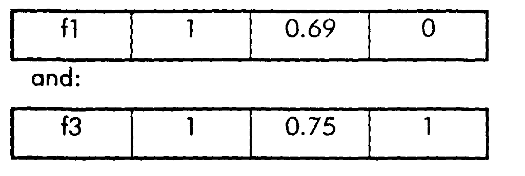
amount of bits bi allocated thereto. Thus, since the carriers with frequencies f1
and f3 carry only one data bit, their associated allocation messages are
transmitted first and have the following contents:
Later on, the allocation messages related to the carriers with frequencies f2 and
f4 are transmitted. They have the following contents:
At the receiver's side, receiver R' interprets the allocation messages and
understands that the carrier with frequency f3, transmitted at an energy level of
0.75 dB, carries 1 data bit which is a copy of the data bit that is modulated on
the carrier with frequency f1, transmitted at a power level of 0.69 dB. Similarly,
the receiver R' learns from the latter two allocation messages that the carrier with
frequency f4, transmitted at a power level of 0.73 dB carries 3 data bits which
are identical to the 3 data bits modulated on the carrier with frequency f2 which
is transmitted at a power level of 0.80 dB.
The functional blocks which form part of the allocation message generator
AMG of Fig. 2, are shown in Fig. 5 where the allocation message generator is
referred to by AMG'. A carrier identification generator CG, a bit amount
generator BG, a power level generator PG and a redundancy information
generator RG generate the information fi, hi, pi and rp respectively to be
embedded in the fields of an allocation message AM. An embedder EM
constitutes the allocation message AM and fills the respective fields with the
information generated by the carrier identification generator CG, the bit amount
generator BG, the power level generator PG and the redundancy information
generator RG. Via the bit allocation means BAM where the allocation messages
AM are included in the bitstream or directly mapped on a specific carrier, the
modulation means MOD, the digital to analogue converter DAC and the line
interface LIN in Fig. 2, the allocation messages AM are transformed into
analogue signals suitable for transmission over the telephone line TL of Fig. 1.
By interpreting the allocation messages, the multicarrier receiver R' knows
that part of the data bits are transmitted twice. The receiver R' now can
demodulate the data bits. The line interface means LIN' and analogue to digital
converter ADC adapt the signal S' transported over the telephone line TL of Fig.
1 and received via input terminal IT', and transform this signal S' into
multicarrier digital data symbols. The interference measurement means IMM
determines for all carriers that transport redundantly transmitted data bits (the
carriers with frequencies f1, f2, f3 and f4 in the above described example), the
amount of narrowbanded interference that affects these carriers. The measured
interference values are then applied to the diversity means DIV which manages
the re-combination of the data bits in an optimal way. The diversity means DIV
in other words decides which bits shall be taken into account and controls the
demodulator DEM and bit de-allocation means BDA so that the re-combined bits
appear at the output OT' of the receiver R'. The way wherein the data bits are
re-combined can take several forms. Selection diversity for instance implies that
the bits which are transmitted on carriers with the best estimated signal to noise
ratio (SNR) are taken for demodulation. A preferred cost-effective
implementation of the invention should use selection diversity since it is close to
optimal when the SNR differs significantly for different versions of the data bits,
and it does not require a high receiver complexity. In Fig. 4A and Fig. 4B, it is
assumed that a radio amateur signal RFI is disturbing the transmission at a
frequency between f2 and f3. The effect of this interferer RFI on the carriers with
frequencies f2 and f3 will be higher than the impact on the carriers with
frequencies f4 and f1 respectively. Consequently, the interference measuring
means IMM measures a higher affection for the carriers with frequencies f3 and
f2 than for the carriers with frequencies f1 and f4 respectively. When the
measured interference values are applied to the diversity means DIV, this
diversity means DIV decides to retrieve the data bits transmitted in the affected
range from the carrier with frequency f1 instead of the carrier with frequency f3,
and from the carrier with frequency f4 instead of the carrier with frequency f2 in
case of selection diversity. Alternatively, instant selection diversity may be applied.
This means that amongst different versions of information symbols, the
information symbol which is closest to a decision point of a constellation diagram
is taken for demodulation. Another alternative diversity method is called
Maximal Ratio Combining
'. Therein, the information symbol that is taken for
demodulation is calculated as a linear combination of different information
symbol versions which are each weighted by a coefficient equal to the SNR of
that version divided by the sum of the SNR's of all information symbol versions.
Yet, in another alternative diversity method named
Equal Gain Combining
', the
information symbol that is taken for demodulation is calculated as the average of
the different versions of that information symbol. The preferred cost-effective
version of the present invention, as already described above, uses selection
diversity for complexity reasons.
The demodulator DEM extracts the cyclic prefix from the transmitted
multicarrier symbols, fast Fourier transforms the symbols to obtain their frequency
domain representation from the time domain representation and demodulates,
e.g. by QAM demodulation, the data from the carriers. Under control of the
diversity means DIV, the bit de-allocation means BDA retrieves the correct
amount of bits from each carrier. Thus, in the affected range,
Amateur Radio
Band
', zero bits are retrieved from the carriers with frequencies f2 and f3, one
bit is retrieved from the carrier with frequency f1, and 3 bits are retrieved from
the carrier with frequency f4. The retrieved bits leave the receiver R' via output
terminal OT'.
A first remark is that the above description of an embodiment of the
present invention is limited to describing the functions performed by the different
blocks drawn in the figures. From this functional description, a person skilled in
the art can derive how to implement each one of the drawn blocks.
A further remark is that, although the data in the above described
embodiment are transported over a telephone line TL, the applicability of the
present invention is not restricted by the transmission medium via which the data
are transported. In particular, any connection between a transmitter T and a
receiver R, e.g. a cable connection, a satellite connection, a radio link through
the air, and so on, may be affected by narrowbanded interference, and thus can
be protected by the method according to the present invention if the data are
modulated on a set of carriers. The invention also is not only related to ADSL
(Asymmetric Digital Subscriber Line) or similar techniques wherein DMT (Discrete
Multi Tone) modulation is used A person skilled in the art will be able to adapt
the above described embodiment for example so that it is applicable to systems
wherein DWMT (Discrete Wavelet Multi Tone) modulation is used. Therein, the
above mentioned Fourier transform and inverse Fourier transtorm are replaced
by wavelet transformations.
It is further noticed that the origin of the narrowbanded interference is of
no importance for applicability of the present invention. Whether the disturbing
signals are transmitted by a radio amateur, as supposed in the above described
example, by a taxi, or by the police, or are caused by metallic noise as in the
above cited article from Peter S. Chow, or are originating from yet another
source is not relevant. Whenever a transmitter T expects that some of the carriers
whereon data have to be modulated, may be affected by narrowbanded
interference, he can protect the data bits transmitted via these carriers by
transmitting these data bits in a redundant way. Carriers laying in the distress
bands for instance also may be protected this way. Via the allocation messages,
the receiver R is told which carriers are modulated with the duplicates of the data
bits.
Another remark is that the modulation type also is irrelevant with respect
to applicability of the present invention. In the above described embodiment,
data are modulated on and demodulated from the set of carriers via QAM
modulation and demodulation respectively. Alternatively, data may be
modulated by phase modulation, frequency modulation, PSK (Phase Shift Keying)
or any other modulation technique.
In the above described embodiment, any data bit transmitted in the
frequency range that may be affected is transmitted twice. As a result, even if 50
percent of the carriers in this range are distorted by interference, all data can still
be retrieved by the receiver R'. Obviously, higher or lower levels of protection
are obtained by modifying the redundancy scheme. Data bits may be transmitted
3 or 4 times to the receiver, data bits may be combined in a linear or more
complex way, and some of the data bits may be excluded for redundant
transmission since loss thereof has no large impact on the performance of the
system. The redundancy scheme, still in alternative versions of the present
invention, may be optimised with respect to throughput of the transmission line.
Copies of data bits that are modulated on carrier f1 not necessarily have to be
allocated to one single other carrier, but may be distributed over more than one
other carrier. In this way, the carriers can be filled better. A disadvantage
however is that in such implementations of the present invention, the contents of
the allocation messages and the means in the receiver R which have to interpret
these allocation messages become more complex. An improved throughput of
the transmission line can also be obtained by allocating additional data bits to
each carrier which can carry more bits than the duplicates of its associated
carrier. In the above described example, f1 and f4 are such carriers.
It is also noticed that, in yet another implementation of the present
invention, data bits may be duplicated and modulated on carriers with
frequencies outside the range that is affected by narrowbanded interference.
While the principles of the invention have been described above in
connection with specific apparatus, it has to be clearly understood that this
description is made only by way of example and not as a limitation on the scope
of the invention.


