EP0854737B1 - Self-cleaning endotracheal tube apparatus - Google Patents
Self-cleaning endotracheal tube apparatus Download PDFInfo
- Publication number
- EP0854737B1 EP0854737B1 EP96933232A EP96933232A EP0854737B1 EP 0854737 B1 EP0854737 B1 EP 0854737B1 EP 96933232 A EP96933232 A EP 96933232A EP 96933232 A EP96933232 A EP 96933232A EP 0854737 B1 EP0854737 B1 EP 0854737B1
- Authority
- EP
- European Patent Office
- Prior art keywords
- catheter
- endotracheal tube
- lungs
- humidified air
- flow
- Prior art date
- Legal status (The legal status is an assumption and is not a legal conclusion. Google has not performed a legal analysis and makes no representation as to the accuracy of the status listed.)
- Expired - Lifetime
Links
Images
Classifications
-
- A—HUMAN NECESSITIES
- A61—MEDICAL OR VETERINARY SCIENCE; HYGIENE
- A61M—DEVICES FOR INTRODUCING MEDIA INTO, OR ONTO, THE BODY; DEVICES FOR TRANSDUCING BODY MEDIA OR FOR TAKING MEDIA FROM THE BODY; DEVICES FOR PRODUCING OR ENDING SLEEP OR STUPOR
- A61M16/00—Devices for influencing the respiratory system of patients by gas treatment, e.g. mouth-to-mouth respiration; Tracheal tubes
- A61M16/04—Tracheal tubes
- A61M16/0463—Tracheal tubes combined with suction tubes, catheters or the like; Outside connections
-
- A—HUMAN NECESSITIES
- A61—MEDICAL OR VETERINARY SCIENCE; HYGIENE
- A61M—DEVICES FOR INTRODUCING MEDIA INTO, OR ONTO, THE BODY; DEVICES FOR TRANSDUCING BODY MEDIA OR FOR TAKING MEDIA FROM THE BODY; DEVICES FOR PRODUCING OR ENDING SLEEP OR STUPOR
- A61M16/00—Devices for influencing the respiratory system of patients by gas treatment, e.g. mouth-to-mouth respiration; Tracheal tubes
- A61M16/0003—Accessories therefor, e.g. sensors, vibrators, negative pressure
- A61M16/0009—Accessories therefor, e.g. sensors, vibrators, negative pressure with sub-atmospheric pressure, e.g. during expiration
- A61M16/0012—Accessories therefor, e.g. sensors, vibrators, negative pressure with sub-atmospheric pressure, e.g. during expiration by Venturi means
-
- A—HUMAN NECESSITIES
- A61—MEDICAL OR VETERINARY SCIENCE; HYGIENE
- A61M—DEVICES FOR INTRODUCING MEDIA INTO, OR ONTO, THE BODY; DEVICES FOR TRANSDUCING BODY MEDIA OR FOR TAKING MEDIA FROM THE BODY; DEVICES FOR PRODUCING OR ENDING SLEEP OR STUPOR
- A61M16/00—Devices for influencing the respiratory system of patients by gas treatment, e.g. mouth-to-mouth respiration; Tracheal tubes
- A61M16/04—Tracheal tubes
- A61M16/0402—Special features for tracheal tubes not otherwise provided for
- A61M16/042—Special features for tracheal tubes not otherwise provided for with separate conduits for in-and expiration gas, e.g. for limited dead volume
-
- A—HUMAN NECESSITIES
- A61—MEDICAL OR VETERINARY SCIENCE; HYGIENE
- A61M—DEVICES FOR INTRODUCING MEDIA INTO, OR ONTO, THE BODY; DEVICES FOR TRANSDUCING BODY MEDIA OR FOR TAKING MEDIA FROM THE BODY; DEVICES FOR PRODUCING OR ENDING SLEEP OR STUPOR
- A61M16/00—Devices for influencing the respiratory system of patients by gas treatment, e.g. mouth-to-mouth respiration; Tracheal tubes
- A61M16/10—Preparation of respiratory gases or vapours
- A61M16/12—Preparation of respiratory gases or vapours by mixing different gases
- A61M16/122—Preparation of respiratory gases or vapours by mixing different gases with dilution
- A61M16/125—Diluting primary gas with ambient air
- A61M16/127—Diluting primary gas with ambient air by Venturi effect, i.e. entrainment mixers
-
- A—HUMAN NECESSITIES
- A61—MEDICAL OR VETERINARY SCIENCE; HYGIENE
- A61M—DEVICES FOR INTRODUCING MEDIA INTO, OR ONTO, THE BODY; DEVICES FOR TRANSDUCING BODY MEDIA OR FOR TAKING MEDIA FROM THE BODY; DEVICES FOR PRODUCING OR ENDING SLEEP OR STUPOR
- A61M25/00—Catheters; Hollow probes
- A61M25/0021—Catheters; Hollow probes characterised by the form of the tubing
- A61M25/0023—Catheters; Hollow probes characterised by the form of the tubing by the form of the lumen, e.g. cross-section, variable diameter
-
- A—HUMAN NECESSITIES
- A61—MEDICAL OR VETERINARY SCIENCE; HYGIENE
- A61M—DEVICES FOR INTRODUCING MEDIA INTO, OR ONTO, THE BODY; DEVICES FOR TRANSDUCING BODY MEDIA OR FOR TAKING MEDIA FROM THE BODY; DEVICES FOR PRODUCING OR ENDING SLEEP OR STUPOR
- A61M16/00—Devices for influencing the respiratory system of patients by gas treatment, e.g. mouth-to-mouth respiration; Tracheal tubes
- A61M16/08—Bellows; Connecting tubes ; Water traps; Patient circuits
- A61M16/0816—Joints or connectors
- A61M16/0833—T- or Y-type connectors, e.g. Y-piece
-
- A—HUMAN NECESSITIES
- A61—MEDICAL OR VETERINARY SCIENCE; HYGIENE
- A61M—DEVICES FOR INTRODUCING MEDIA INTO, OR ONTO, THE BODY; DEVICES FOR TRANSDUCING BODY MEDIA OR FOR TAKING MEDIA FROM THE BODY; DEVICES FOR PRODUCING OR ENDING SLEEP OR STUPOR
- A61M2205/00—General characteristics of the apparatus
- A61M2205/32—General characteristics of the apparatus with radio-opaque indicia
Definitions
- the present invention relates to medical devices used to assist breathing. More particularly, an endotracheal tube apparatus is disclosed which can safely and efficiently impart air and oxygen to the lungs while preventing the harmful build up of encrusted mucus deposits on critical parts of the apparatus.
- ITV involves the introduction of an endotracheal tube and a small, open ended catheter within that tube into the trachea of a human or animal.
- the distal ends of the endotracheal tube and catheter are positioned to rest at or near the carina of the lungs.
- a well-humidified oxygen/air mixture is then introduced through the catheter to provide oxygen more directly to the lungs.
- a second problem which is addressed in the inventor's previous U.S. Patent No. 5,186,167, involves the damage to the lungs and additional dead space which can be created by air shooting out the open end of a catheter and into the lungs at high peak airway pressures (HPAP). Such a jet stream of air has a tendency to overinflate the lungs.
- HPAP peak airway pressures
- diffusers were disclosed which could be placed at the distal end of the catheter to break up this jet stream of air.
- 5,186,167 therefore discloses an apparatus for intratracheal ventilation of human or animal lungs, the apparatus comprising a catheter, having proximal and distal ends; a source of humidified air flow connected to the proximal end of said catheter to provide humidified air flow through said catheter: and a flow-reversing catheter tip affixed to the distal end of said catheter having an exit port directed away from said lungs.
- a third problem with commonly used ITV equipment is the collection of mucus on the catheter and endotracheal tube.
- mucus secretions are removed from the lungs and the trachea by the mucociliary action of the epithelial cells and through coughing.
- This mucus removal mechanism is generally not available, though, to an intubated patient. Instead, for an intubated patient, the mucus in the trachea and lungs has a tendency to collect on the surface of both the catheter and endotracheal tube to then dry to become a crusty film as air is continually passed across it. As this encrusted mucus accumulates on the catheter, it begins to clog them. This accumulation of encrusted mucus also can promote harmful bacterial growth.
- the catheter frequently needs to be removed and cleaned.
- the frequent removal, cleaning and reinsertion of the catheter involves significant inconvenience to the patient and health care worker as well as the dangers associated with interruption of patient ventilation.
- the present invention provides an endotracheal tube apparatus which can efficiently impart air to the lungs while preventing the harmful build up of mucus deposits on critical parts of the apparatus.
- This endotracheal tube apparatus features an endotracheal tube and a catheter, with a reverse thrust catheter (RTC) tip, within the endotracheal tube.
- RTC reverse thrust catheter
- the catheter is used to bring fresh air into the lungs while the endotracheal tube is used to allow stale air to be removed from the lungs.
- the RTC tip functions to reverse the flow of air coming through the catheter so that such air flow is no longer directed at the lungs.
- the endotracheal tube and catheter are inserted to a point slightly above the carina of the lungs and supplied with humidified air into which a small amount of water droplets are entrained.
- the humidified air can consist of a mixture of room air and oxygen which has been passed through a humidifier. Water droplets can be added to this humidified air either through a micropump or a bubbler.
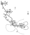
- FIG. 1 shows a preferred form of endotracheal tube apparatus 10 for the present invention.
- This endotracheal apparatus 10 features an endotracheal tube 12 and a tubular catheter 14 which is concentrically fitted within the endotracheal tube 12.
- Both the endotracheal tube 12 and catheter 14 are preferably formed of a flexible plastic, such as polyvinylchloride (PVC) or silicone rubber, which is suitable for insertion into the trachea 16 of a human 18.
- PVC polyvinylchloride
- silicone rubber silicone rubber
- the endotracheal tube 12 should be of a diameter which fits comfortably against the inner surface of the trachea 16.
- Both the catheter 14 and endotracheal tube 12 should be long enough to reach from the point of entry into the human body at their proximal ends 20, 22 to a point which is slightly above (i.e., approximately 1 cm) the carina 28 of the lungs at their distal ends 24, 26.
- a detectable marker 30, 31, such as a radio opaque tantalum band, is preferably embedded in both the catheter's distal end 24 and endotracheal tube's distal end 26. These detectable markers 30, 31 can be monitored with x-rays and roentgenographic films.
- the point of entry into the human body for the catheter 14 and endotracheal tube 12 can vary depending upon the application. For example, common points of entry include the patient's nose, mouth or throat (i.e., resulting from a tracheostomy).
- the endotracheal tube 12 is preferably attached to a T-piece connector 32.
- This T-piece connector 32 has ports 34, 35 to which mechanical ventilation devices can be attached to further help with the inspiration and expiration of air.
- a mechanical ventilator to assist inspiration such as a balloon ventilator (not shown)
- CPAP continuous positive airway pressure
- a mechanical regulator to assist expiration can be attached to port 35 to provide a positive end expiratory pressure (PEEP).
- PEEP positive end expiratory pressure
- the port 35 can also be used to allow dissolved mucus which is expelled from the endotracheal tube 12 to collect in a suitable receptacle, such as glass beaker 37.
- the catheter 14 would typically pass through the T-piece connector 32 until it reaches the catheter connector 36.
- the external tubing 38, 40 should be made from a flexible plastic such as polyvinylchloride (PVC), silicone rubber or polytetrafluoroethylene (PTFE or TEFLON®).
- PVC polyvinylchloride
- PTFE polytetrafluoroethylene
- flexible tubing 38 should be clad with insulating material, such as multiple layers of a thin plastic wrap.
- Humidified air is supplied to flexible tubing 38 from flow meter 42 and humidifier 44.
- the flow meter 42 will mix air and oxygen at room temperature. Both the air and oxygen can advantageously be stored in compressed form in tanks 46, 48 to allow the quality, flow rate and composition of the mixture to be carefully controlled.
- the air to oxygen content of the mixture can be adjusted by flow meter 42 as needed to range from 100% air to 100% oxygen. Usually, oxygen content will be adjusted from 0% to 80% of the mixture.
- the endotracheal tube apparatus 10 of the present invention can be operated at a variety of different flow rates.
- Respiratory Rate Flow Rate Pressure 20/min 4.8 liters/min 20.7 kPa (3 psi) 40/min 9.6 liters/min 41.4 kPa (6 psi) 60/min 14.4 liters/min 68.9 kPa (10 psi) 80/min 19.2 liters/min 103.4 kPa (15 psi)
- a humidifier 44 After air and oxygen are mixed at flow meter 42, the mixture is sent to a humidifier 44 through plastic supply tubing 54 to be humidified.
- This humidifier is typically composed of a reservoir 50 partially filled with sterile water and heated by suitable means, such as an electrical heater 51, to a temperature of about 37 -40 °C.
- a cover 52 is affixed to the top of the reservoir 50 to prevent contamination of the sterile water and allow tubes 38 and 54 to access the reservoir.
- the air/oxygen mixture coming from the flow meter 42 will flow into the reservoir above the heated water and mix with water vapors. After this mixture becomes humidified with the water vapors, it leaves the humidifier 44 through tubing 38.
- a second reservoir 56 of sterile water or saline solution is provided from which micropump 58 pumps liquid at the appropriate rate.
- a humidified air flow rate of 15 liters per minute it has been found that 1 drop of water or saline per minute (i.e., 0.10 ml/min) is a suitable amount to add to the humidified air.
- the mucus clearing effects of adding water or saline to the humidified air seem to be more pronounced at higher flow rates, such as 12-18 liters per minute.
- water droplets can be entrained in the humidifier 44 by extending the outlet 60 of the air/oxygen input tube 54 below the reservoir 50 water level. By so extending the tubing 54, a "bubbler" will be created in the reservoir 50. Nonetheless, this approach to entraining water in the humidified air is less preferred because it is more difficult to control the amount of water which is being entrained. If too many water droplets are entrained in the humidified air, these water droplets may begin to be deposited in the lungs rather than simply clearing away mucus on the catheter and endotracheal tube.
- the entrained water droplets keep the endotracheal tube 12 and catheter 14 clean by dissolving mucus the droplets come in contact with and allowing the dissolved mucus to be easily expelled through the endotracheal tube 12. In the absence of such droplets, the mucus will dry and harden around the catheter and endotracheal tube surfaces, particularly at their distal end 24, 26.
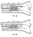
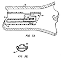
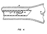
- catheter tips 61 are the reverse thrust catheter (RTC) tips 62, 64, 80 shown in FIGS. 2A-B, 3A-B and 4.
- RTC reverse thrust catheter
- These types of catheter tips 62, 64, 80 are designed to direct the flow of air, oxygen and entrained water droplets exiting from the distal end 24 of the catheter away from the carina 28 of the lungs. Accordingly, gas exit ports 66, 68, 78 of these RTC tips 62, 64, 80 face away from the carina 28 and toward the proximal end 20 of the catheter 14.
- the RTC tips 62, 64 are preferably formed of a medically suitable plastic, such as nylon, polyvinylchloride (PVC), silicone rubber or polytetrafluoroethylene (PTFE or TEFLON®), and can be made as an integral part of the catheter 14. Alternatively, the RTC tips 62, 64 can be affixed to the catheter through plastic welding or a medically acceptable adhesive.
- a medically suitable plastic such as nylon, polyvinylchloride (PVC), silicone rubber or polytetrafluoroethylene (PTFE or TEFLON®
- FIGS. 2A-B shows that the air/oxygen flow can first be diffused through holes 70 at the distal end 24 of the catheter 14 and then directed away from the carina through an annular opening 66 in the catheter tip 62.
- FIGS. 3A-B show that a hook-like configuration of catheter tip 64 can be used to achieve a similar result.
- FIG. 4 illustrates how the catheter 76 and catheter tip 80 can even be formed as an integral part of the endotracheal tube 14 using a similar hook-like configuration for the catheter tip 80.
- the width of gap "a" in the exit ports 66, 68, 78 determines the flow-pressure characteristics at the level of the carina for any given flow rate.
- the gap "a” should preferably be kept small, for example between 0.127 mm and 0.508 mm (0.005 and 0.020 inches), to create a venturi effect at the carina. Without the entrained water droplets of the present invention, such small catheter tip exit ports 66, 68, 78 have a tendency to become clogged with dried mucus. By adding water droplets to the humidified air, though, any mucus which collects at these exit ports is usually dissolved and expelled.
- the endotracheal tube 12 and catheter 14 are first inserted into an appropriate patient orifice leading to the lungs, such as the patient's mouth.
- a guide wire (not shown) can be placed in the catheter to help steer the catheter until the catheter has reached its operational position.
- the positioning of the endotracheal tube 12 and catheter 14 can be checked using x-rays and roentgenographic films.
- the detectable markers 30, 31 should indicate that the distal ends 24, 26 of both are slightly above the patient's carina 28.
- the endotracheal tube 12 and catheter 14 After the endotracheal tube 12 and catheter 14 have been correctly inserted, they can then be attached to the remaining equipment for supplying humidified air to the patient, including the T-piece connector 32, humidifier 44 and catheter connector piece 36.
- a proper air/oxygen mixture and flow rate such as 15 liters per minute, should be set at the flow meter 42 with an accompanying rate of pumped water, such as one drop per minute, set at the micropump 58. Having made the proper setting, the endotracheal tube apparatus 10 can be used to assist patient ventilation in a self-cleaning manner.
- the mechanically assisted ventilation technique described here can be employed with the endotracheal tube apparatus 10 of the present invention.
- ITPV intratracheal pulmonary ventilation
- all the fresh air and oxygen is introduced through the catheter 14.
- the endotracheal tube 12 is used for expiration only.
- the expiration though this endotracheal tube 12 is controlled by an expiratory valve (not shown) which is attached, for example, to port 35 of the endotracheal T-piece connector 32.
- an expiratory valve not shown
- the expiration valve is closed, all of the air and oxygen from the catheter 14 enters the lungs as shown, for example, in FIG. 2A.
- CPAP continuous positive airway pressure
Abstract
Description
| Respiratory Rate | | Pressure | |
| 20/min | 4.8 liters/min | 20.7 kPa (3 psi) | |
| 40/min | 9.6 liters/min | 41.4 kPa (6 psi) | |
| 60/min | 14.4 liters/min | 68.9 kPa (10 psi) | |
| 80/min | 19.2 liters/min | 103.4 kPa (15 psi) |
Claims (13)
- Apparatus (10) for intratracheal ventilation of human or animal lungs, comprising a catheter (14) having proximal (20) and distal (24) ends, a source of humidified air flow connected to the proximal end (20) of said catheter (14) to provide humidified air flow through said catheter, a flow-reversing catheter tip (62,64,80) affixed to the distal end (24) of said catheter (14) having at least one exit port (66,68,78) directed away from said lungs, the apparatus further comprising an endotracheal tube (12) guiding the catheter (14) inside the trachea, characterised in that the endotracheal tube (12) is long enough that its distal end can be positioned at a point at or near the carina of the lungs and the catheter (14) is positioned within said endotracheal tube (12) such that the at least one exit port (66,68,78) of the flow-reversing catheter tip (62,64,80) is located within the endotracheal tube (12) and close to its distal end, the apparatus (10) further comprising means (56,58) to entrain liquid droplets to said humidified air flow so that the air flow in said catheter (14) consists of humidified air with entrained liquid droplets.
- Intratracheal ventilation apparatus according to claim 1, characterised in that said catheter (14) is formed of a flexible plastic, e.g. of polyvinylchloride (PVC).
- Intratracheal ventilation apparatus according to claim 1 or 2, characterised in that said catheter (14) and flow-reversing catheter tip (62,64,80) are formed as an integral part of said endotracheal tube (12).
- Intratracheal ventilation apparatus according to one of the preceding claims, characterised in that said source of humidified air comprises a compressed oxygen tank (46), a compressed air tank (48), a flow meter (42) connected to said oxygen and air tanks to mix oxygen and air in desired proportions, and a humidifier (44) connected to said flow meter to humidify the mixture of oxygen and air received from the flow meter (42).
- Intratracheal ventilation apparatus according to one of the preceding claims, characterised in that said liquid droplets are sterile water.
- Intratracheal ventilation apparatus according to one of the preceding claims, characterised in that said liquid droplets are saline solution.
- Intratracheal ventilation apparatus according to one of the preceding claims, characterised in that said means (56,58) to add liquid droplets comprises a reservoir (56) of sterile water, a pump (58) for pumping water from said reservoir (56), and a connector piece (36) operably connected to said pump (58) and said catheter (14) for pumping water droplets into the humidified air passing through said catheter (14).
- Intratracheal ventilation apparatus according to one of the preceding claims, characterised in that the flow-reversing catheter tip (62,64,80) comprises a gap (a) in the exit ports (66,68,78) that determines the flow-pressure characteristics at the level of the carina.
- Intratracheal ventilation apparatus according to claim 8, characterised in that the gap (a) in the exit ports (66, 68, 78) is between 0.127 mm and 0.508 mm, to create a venturi effect at the carina and that by adding water droplets to the humidified air, mucus which collects at these exit ports is dissolved and expelled through the tracheal tube (12).
- Intratracheal ventilation apparatus according to one of the preceding claims, characterised in that the apparatus (10) is designed to supply a humidified air flow rate of 12 to 18 liters per minute and to entrain approximately 1 drop of water to said humidified air flow every minute.
- Intratracheal ventilation apparatus according to one of claims 1 to 9, characterised in that the apparatus (10) is designed to supply a humidified air flow rate of 15 liters per minute and to add 0.10 ml water per minute to said humidified air.
- Intratracheal ventilation apparatus according to one of the preceding claims, characterised in that the selected point above the lungs is 1 cm above the carina (28) of the lungs and the endotracheal tube (12) and catheter (14) are long enough to reach from a point of entry into the human (18) or animal body at their proximal ends (20,22) to said selected point at their distal ends (24,26).
- Intratracheal ventilation apparatus according to one of the preceding claims, characterised in that detectable markers (30,31) are affixed to the distal end (24) of said catheter (14) and/or the distal end (26) of said endotracheal tube (12) allowing said catheter (14) and/or endotracheal tube (12) to be inserted to a selected point above the lungs to be confirmed with x-rays.
Applications Claiming Priority (3)
| Application Number | Priority Date | Filing Date | Title |
|---|---|---|---|
| US541846 | 1995-10-10 | ||
| US08/541,846 US5687714A (en) | 1995-10-10 | 1995-10-10 | Self-cleaning endotracheal tube apparatus |
| PCT/US1996/015823 WO1997013540A1 (en) | 1995-10-10 | 1996-10-02 | Self-cleaning endotracheal tube apparatus |
Publications (2)
| Publication Number | Publication Date |
|---|---|
| EP0854737A1 EP0854737A1 (en) | 1998-07-29 |
| EP0854737B1 true EP0854737B1 (en) | 2004-01-14 |
Family
ID=24161333
Family Applications (1)
| Application Number | Title | Priority Date | Filing Date |
|---|---|---|---|
| EP96933232A Expired - Lifetime EP0854737B1 (en) | 1995-10-10 | 1996-10-02 | Self-cleaning endotracheal tube apparatus |
Country Status (8)
| Country | Link |
|---|---|
| US (1) | US5687714A (en) |
| EP (1) | EP0854737B1 (en) |
| JP (1) | JPH11513296A (en) |
| AT (1) | ATE257720T1 (en) |
| AU (1) | AU709977B2 (en) |
| DE (1) | DE69631337T2 (en) |
| ES (1) | ES2213781T3 (en) |
| WO (1) | WO1997013540A1 (en) |
Families Citing this family (106)
| Publication number | Priority date | Publication date | Assignee | Title |
|---|---|---|---|---|
| US6676627B1 (en) * | 1990-08-06 | 2004-01-13 | Possis Medical, Inc. | Crossflow thrombectomy catheter and system |
| US8557054B2 (en) * | 1996-03-11 | 2013-10-15 | Orlando Morejon | Endotracheal tube cleaning apparatus |
| US6579224B1 (en) * | 1999-10-11 | 2003-06-17 | Uromedica, Inc. | Apparatus and method for inserting an adjustable implantable genitourinary device |
| US6419624B1 (en) * | 1999-10-11 | 2002-07-16 | Uromedica, Inc. | Apparatus and method for inserting an adjustable implantable genitourinary device |
| US6645138B2 (en) * | 1997-09-12 | 2003-11-11 | Uromedica, Inc. | Adjustable implantable genitourinary device |
| US7364540B1 (en) | 1997-06-12 | 2008-04-29 | Uromedica, Inc. | Implantable device and method for adjustably restricting a body lumen |
| US6655382B1 (en) * | 1997-09-18 | 2003-12-02 | The United States Of America As Represented By The Secretary Of Health And Human Services | Spontaneous breathing apparatus and method |
| US5957134A (en) * | 1997-11-18 | 1999-09-28 | Lee; Han Shik | Anesthesia delivery system |
| US5855203A (en) * | 1997-12-19 | 1999-01-05 | Matter; Jean-Paul | Respiratory circuit with in vivo sterilization |
| US9586023B2 (en) | 1998-02-06 | 2017-03-07 | Boston Scientific Limited | Direct stream hydrodynamic catheter system |
| US7879022B2 (en) | 1998-02-06 | 2011-02-01 | Medrad, Inc. | Rapid exchange fluid jet thrombectomy device and method |
| US5896854A (en) * | 1998-05-04 | 1999-04-27 | Valley Inspired Products, Llc | Tracheal gas insufflation system |
| US5997498A (en) * | 1998-05-07 | 1999-12-07 | Johns Hopkins University | Inline air humidifier, a system for humidifying air and methods related thereto |
| SE512807C2 (en) * | 1998-09-02 | 2000-05-15 | Bjoern Flodin | Device for supplying inhalation gas to and removing exhalation gas from a patient |
| US6836794B1 (en) * | 1998-09-21 | 2004-12-28 | Microsoft Corporation | Method and system for assigning and publishing applications |
| US7431031B2 (en) * | 1998-12-22 | 2008-10-07 | Ric Investments, Llc | Insufflation system and method |
| US6102042A (en) | 1998-12-22 | 2000-08-15 | Respironics, Inc. | Insufflation system, attachment and method |
| AU4684500A (en) | 1999-04-30 | 2000-11-17 | Uromedica, Inc. | Method and apparatus for adjustable sling for treatment of urinary stress incontinence |
| US6470888B1 (en) | 1999-11-08 | 2002-10-29 | Freya, Llc | System for in vivo sterilization of a respiratory circuit |
| SE522896C2 (en) * | 2000-02-25 | 2004-03-16 | Bjoern Flodin | Device for collecting liquid from exhaled gas from a patient |
| US6609520B1 (en) | 2000-10-31 | 2003-08-26 | Kimberly-Clark Worldwide, Inc. | Closed suction catheter adaptor and assembly containing the same |
| US6769430B1 (en) | 2000-10-31 | 2004-08-03 | Kimberly-Clark Worldwide, Inc. | Heat and moisture exchanger adaptor for closed suction catheter assembly and system containing the same |
| US7107991B2 (en) | 2001-09-28 | 2006-09-19 | The United States Of America As Represented By The Department Of Health & Human Services | Endotracheal tube using leak hole to lower dead space |
| US6588427B1 (en) | 2002-02-25 | 2003-07-08 | Kimberly-Clark Worldwide, Inc. | Heat and moisture exchanger adapter to closed suction catheter assembly and system having improved catheter cleaning |
| US20060129091A1 (en) | 2004-12-10 | 2006-06-15 | Possis Medical, Inc. | Enhanced cross stream mechanical thrombectomy catheter with backloading manifold |
| US7588033B2 (en) | 2003-06-18 | 2009-09-15 | Breathe Technologies, Inc. | Methods, systems and devices for improving ventilation in a lung area |
| DE10337138A1 (en) | 2003-08-11 | 2005-03-17 | Freitag, Lutz, Dr. | Method and arrangement for the respiratory assistance of a patient as well as tracheal prosthesis and catheter |
| US8381729B2 (en) | 2003-06-18 | 2013-02-26 | Breathe Technologies, Inc. | Methods and devices for minimally invasive respiratory support |
| JP2007506480A (en) | 2003-08-18 | 2007-03-22 | ワンドカ,アンソニー・ディ | Methods and apparatus for non-invasive ventilation with a nasal interface |
| US7051737B2 (en) * | 2004-02-05 | 2006-05-30 | The United States Of America As Represented By The Department Of Health And Human Sevices | Mucus shaving apparatus for endotracheal tubes |
| US20100261951A1 (en) * | 2004-02-23 | 2010-10-14 | Uromedica, Inc. | Method and apparatus for an adjustable implantable continence device |
| US20060241339A1 (en) * | 2005-02-23 | 2006-10-26 | Cook Timothy C | Method and apparatus for an adjustable implantable continence device |
| US7572244B2 (en) | 2004-08-02 | 2009-08-11 | Medrad, Inc. | Miniature cross stream thrombectomy catheter |
| US7503328B2 (en) * | 2005-03-15 | 2009-03-17 | The United States Of America As Represented By The Secretary Of The Department Of Health And Human Services | Mucus slurping endotracheal tube |
| DE102005021470A1 (en) * | 2005-05-10 | 2006-11-16 | Tracoe Medical Gmbh | Introducer for percutaneous tracheostomy |
| AU2006266564B2 (en) | 2005-07-01 | 2012-03-22 | Fisher & Paykel Healthcare Limited | A breathing assistance apparatus with a manifold to add auxiliary gases to ambient gases |
| US7478636B2 (en) * | 2005-08-08 | 2009-01-20 | Kimberly-Clark Worldwide, Inc. | Multilumen tracheal catheter to prevent cross contamination |
| US7581541B2 (en) * | 2005-08-08 | 2009-09-01 | Kimberly-Clark Worldwide, Inc. | Multilumen tracheal catheter |
| US7293561B2 (en) * | 2005-08-25 | 2007-11-13 | Kimberly-Clark Worldwide, Inc. | Low profile adapter for tracheal tubes |
| US20070044807A1 (en) * | 2005-08-25 | 2007-03-01 | Kimberly-Clark Worldwide, Inc. | Multilumen tracheal catheter with rinse lumen |
| EP1926517A2 (en) | 2005-09-20 | 2008-06-04 | Lutz Freitag | Systems, methods and apparatus for respiratory support of a patient |
| US8012117B2 (en) * | 2007-02-06 | 2011-09-06 | Medrad, Inc. | Miniature flexible thrombectomy catheter |
| US20080188793A1 (en) | 2007-02-06 | 2008-08-07 | Possis Medical, Inc. | Miniature flexible thrombectomy catheter |
| US20070089748A1 (en) * | 2005-10-26 | 2007-04-26 | Madsen Edward B | Tracheal catheter with closeable suction lumen |
| US20070113855A1 (en) * | 2005-11-18 | 2007-05-24 | Kimberly-Clark Worldwide, Inc. | Respiratory apparatus with improved seal |
| US8162878B2 (en) | 2005-12-05 | 2012-04-24 | Medrad, Inc. | Exhaust-pressure-operated balloon catheter system |
| CN101541365A (en) | 2006-05-18 | 2009-09-23 | 呼吸科技公司 | Tracheostoma tracheotomy method and device |
| US7762006B2 (en) * | 2006-06-14 | 2010-07-27 | Siestamed, Technologies | Medical equipment drying device |
| US20080078406A1 (en) * | 2006-09-29 | 2008-04-03 | Jessica Clayton | Endotracheal tube and technique for using the same |
| US8381728B2 (en) * | 2007-04-18 | 2013-02-26 | Chamkurkishtiah P. Rao | Self-cleaning and sterilizing endotracheal and tracheostomy tube |
| WO2008144589A1 (en) * | 2007-05-18 | 2008-11-27 | Breathe Technologies, Inc. | Methods and devices for sensing respiration and providing ventilation therapy |
| US8974418B2 (en) * | 2007-06-12 | 2015-03-10 | Boston Scientific Limited | Forwardly directed fluid jet crossing catheter |
| US20080319386A1 (en) * | 2007-06-20 | 2008-12-25 | Possis Medical, Inc. | Forwardly directable fluid jet crossing catheter |
| US8567399B2 (en) | 2007-09-26 | 2013-10-29 | Breathe Technologies, Inc. | Methods and devices for providing inspiratory and expiratory flow relief during ventilation therapy |
| JP5513392B2 (en) | 2007-09-26 | 2014-06-04 | ブリーズ・テクノロジーズ・インコーポレーテッド | Method and apparatus for treating sleep apnea |
| WO2009079539A1 (en) | 2007-12-17 | 2009-06-25 | Medrad, Inc. | Rheolytic thrombectomy catheter with self-inflation distal balloon |
| WO2009082669A1 (en) | 2007-12-26 | 2009-07-02 | Medrad, Inc. | Rheolytic thrombectomy catheter with self-inflating proximal balloon with drug infusion capabilities |
| US8133326B2 (en) * | 2008-01-14 | 2012-03-13 | C.R. Bard, Inc. | Endotracheal tube cleaning devices and methods of removing mucus accumulations from endotracheal tubes |
| DE112009000700T5 (en) | 2008-03-20 | 2011-02-10 | Medrad, Inc. | Hydrodynamic direct current catheter system |
| US8770193B2 (en) | 2008-04-18 | 2014-07-08 | Breathe Technologies, Inc. | Methods and devices for sensing respiration and controlling ventilator functions |
| WO2009151791A2 (en) | 2008-04-18 | 2009-12-17 | Breathe Technologies, Inc. | Methods and devices for sensing respiration and controlling ventilator functions |
| JP5715950B2 (en) | 2008-08-22 | 2015-05-13 | ブリーズ・テクノロジーズ・インコーポレーテッド | Method and apparatus for providing mechanical ventilation with an open airway interface |
| EP2344791B1 (en) | 2008-10-01 | 2016-05-18 | Breathe Technologies, Inc. | Ventilator with biofeedback monitoring and control for improving patient activity and health |
| WO2010047672A1 (en) * | 2008-10-20 | 2010-04-29 | Rao Chamkurkishtiah P | Self-cleaning and sterilizing endotracheal and tracheostomy tube |
| CN102264423A (en) * | 2008-10-24 | 2011-11-30 | 呼吸医疗技术有限公司 | Method and system for ventilation |
| US9132250B2 (en) | 2009-09-03 | 2015-09-15 | Breathe Technologies, Inc. | Methods, systems and devices for non-invasive ventilation including a non-sealing ventilation interface with an entrainment port and/or pressure feature |
| WO2011126812A1 (en) | 2010-03-29 | 2011-10-13 | Endoclear, Llc | Airway cleaning and visualization |
| EP2393538B1 (en) | 2009-02-06 | 2017-10-18 | Endoclear LLC | Devices for cleaning endotracheal tubes |
| US8468637B2 (en) | 2009-02-06 | 2013-06-25 | Endoclear Llc | Mechanically-actuated endotracheal tube cleaning device |
| US9962512B2 (en) | 2009-04-02 | 2018-05-08 | Breathe Technologies, Inc. | Methods, systems and devices for non-invasive ventilation including a non-sealing ventilation interface with a free space nozzle feature |
| EP4218876A1 (en) | 2009-04-02 | 2023-08-02 | Breathe Technologies, Inc. | Systems for non-invasive open ventilation with gas delivery nozzles within an outer tube |
| US20100263672A1 (en) * | 2009-04-15 | 2010-10-21 | Nand Kishore Acharya | My personal clean air |
| CN102762250B (en) | 2009-09-03 | 2017-09-26 | 呼吸科技公司 | Mthods, systems and devices for including the invasive ventilation with entrainment port and/or the non-tight vented interface of pressure characteristic |
| US8398579B2 (en) * | 2009-12-16 | 2013-03-19 | Medrad, Inc. | Catheter including composite guide and methods for use of the same |
| JP5346277B2 (en) | 2009-12-28 | 2013-11-20 | ユニ・チャーム株式会社 | Pants-type disposable wearing articles |
| USD699348S1 (en) | 2010-01-27 | 2014-02-11 | Orlando Morejon | Handle |
| US20110180072A1 (en) * | 2010-01-27 | 2011-07-28 | Orlando Morejon | Assembly and method of facilitating the cleaning of an endotracheal tube |
| US20110186052A1 (en) * | 2010-02-01 | 2011-08-04 | Orlando Morejon | Cleaning assembly for an endotracheal tube |
| US20110197894A1 (en) * | 2010-02-18 | 2011-08-18 | Orlando Morejon | Endotracheal tube cleaning apparatus |
| GB201009379D0 (en) * | 2010-06-04 | 2010-07-21 | Univ Edinburgh | Method, apparatus, computer program and system for measuring oscillatory motion |
| EP2605836A4 (en) | 2010-08-16 | 2016-06-01 | Breathe Technologies Inc | Methods, systems and devices using lox to provide ventilatory support |
| CN103124575B (en) | 2010-09-30 | 2015-12-16 | 呼吸科技公司 | For the mthods, systems and devices of moistening respiratory tract |
| AU2012285818B2 (en) | 2011-07-20 | 2015-07-02 | Brigham Young University | Hydrogel materials incorporating eluting ceragenin compound |
| WO2013063520A1 (en) | 2011-10-27 | 2013-05-02 | Endoclear, Llc | Endotracheal tube coupling adapters |
| WO2014089028A1 (en) | 2012-12-04 | 2014-06-12 | Endoclear Llc | Suction cleaning devices, systems and methods |
| JP6294352B2 (en) | 2013-01-07 | 2018-03-14 | ブリガム・ヤング・ユニバーシティBrigham Young University | Methods for reducing cell proliferation and treating certain diseases |
| CN110420211A (en) | 2013-03-15 | 2019-11-08 | 布莱阿姆青年大学 | The method for treating inflammation, autoimmune disease and pain |
| US10568893B2 (en) | 2013-03-15 | 2020-02-25 | Brigham Young University | Methods for treating inflammation, autoimmune disorders and pain |
| US11524015B2 (en) | 2013-03-15 | 2022-12-13 | Brigham Young University | Methods for treating inflammation, autoimmune disorders and pain |
| US11690855B2 (en) | 2013-10-17 | 2023-07-04 | Brigham Young University | Methods for treating lung infections and inflammation |
| US20150203527A1 (en) | 2014-01-23 | 2015-07-23 | Brigham Young University | Cationic steroidal antimicrobials |
| JP6326568B2 (en) * | 2014-01-31 | 2018-05-23 | 株式会社メトラン | Respiratory device |
| CA2844321C (en) | 2014-02-27 | 2021-03-16 | Brigham Young University | Cationic steroidal antimicrobial compounds |
| WO2015187583A1 (en) | 2014-06-03 | 2015-12-10 | Endoclear Llc | Cleaning devices, systems and methods |
| US10441595B2 (en) | 2014-06-26 | 2019-10-15 | Brigham Young University | Methods for treating fungal infections |
| US10238665B2 (en) | 2014-06-26 | 2019-03-26 | Brigham Young University | Methods for treating fungal infections |
| US11395897B1 (en) | 2014-06-27 | 2022-07-26 | Orlando Morejon | Connector assembly for a medical ventilator system |
| US10279137B1 (en) | 2014-06-27 | 2019-05-07 | Orlando Morejon | Connector assembly for a medical ventilator system |
| US10227376B2 (en) | 2014-08-22 | 2019-03-12 | Brigham Young University | Radiolabeled cationic steroid antimicrobials and diagnostic methods |
| US10155788B2 (en) | 2014-10-07 | 2018-12-18 | Brigham Young University | Cationic steroidal antimicrobial prodrug compositions and uses thereof |
| WO2016172543A1 (en) | 2015-04-22 | 2016-10-27 | Savage Paul B | Methods for the synthesis of ceragenins |
| US20170080128A1 (en) * | 2015-09-21 | 2017-03-23 | Brigham Young University | Novel endotracheal tube for the reduction of intubation-related complication in neonates and babies |
| US10226550B2 (en) | 2016-03-11 | 2019-03-12 | Brigham Young University | Cationic steroidal antimicrobial compositions for the treatment of dermal tissue |
| US10959433B2 (en) | 2017-03-21 | 2021-03-30 | Brigham Young University | Use of cationic steroidal antimicrobials for sporicidal activity |
| US10792449B2 (en) | 2017-10-03 | 2020-10-06 | Breathe Technologies, Inc. | Patient interface with integrated jet pump |
| US11510766B2 (en) | 2019-02-14 | 2022-11-29 | Uromedica, Inc. | Method and apparatus for monitoring implantable device for urinary continence |
Family Cites Families (11)
| Publication number | Priority date | Publication date | Assignee | Title |
|---|---|---|---|---|
| DE3435849A1 (en) * | 1984-09-29 | 1986-04-30 | Paul Peter Prof. Dr.med. 4400 Münster Lunkenheimer | AIR PULSE GENERATOR IN VENTILATORS |
| US4621632A (en) * | 1984-11-01 | 1986-11-11 | Bear Medical Systems, Inc. | Humidifier system |
| US4770168A (en) * | 1985-12-16 | 1988-09-13 | Tibor Rusz | Electrically controllable anesthesia vaporizer |
| US5231983A (en) * | 1990-01-03 | 1993-08-03 | Minnesota Mining And Manufacturing | Method of and apparatus for the aerosol administration of medication |
| US5186167A (en) * | 1990-10-31 | 1993-02-16 | The United States Of America As Represented By The Department Of Health And Human Services | Catheter tip for intratracheal ventilation and intratracheal pulmonary ventilation |
| DE69127826T2 (en) * | 1990-12-17 | 1998-04-09 | Minnesota Mining & Mfg | INHALATION DEVICE |
| US5226411A (en) * | 1991-03-07 | 1993-07-13 | Walter Levine | Aerosol nebulizer heater |
| US5355872B1 (en) * | 1992-03-04 | 1998-10-20 | John H Riggs | Low flow rate nebulizer apparatus and method of nebulization |
| US5291882A (en) * | 1992-05-11 | 1994-03-08 | Makhoul Imad R | Multi-lumen ITPV endotracheal tube |
| DE4221931C1 (en) * | 1992-07-03 | 1993-07-08 | Harald Dr. 8521 Moehrendorf De Mang | |
| FR2709251B1 (en) * | 1993-08-26 | 1995-11-10 | Georges Boussignac | Breathing assistance tube. |
-
1995
- 1995-10-10 US US08/541,846 patent/US5687714A/en not_active Expired - Lifetime
-
1996
- 1996-10-02 AU AU72048/96A patent/AU709977B2/en not_active Ceased
- 1996-10-02 DE DE69631337T patent/DE69631337T2/en not_active Expired - Fee Related
- 1996-10-02 EP EP96933232A patent/EP0854737B1/en not_active Expired - Lifetime
- 1996-10-02 WO PCT/US1996/015823 patent/WO1997013540A1/en active IP Right Grant
- 1996-10-02 ES ES96933232T patent/ES2213781T3/en not_active Expired - Lifetime
- 1996-10-02 JP JP9515095A patent/JPH11513296A/en not_active Ceased
- 1996-10-02 AT AT96933232T patent/ATE257720T1/en not_active IP Right Cessation
Also Published As
| Publication number | Publication date |
|---|---|
| WO1997013540A1 (en) | 1997-04-17 |
| EP0854737A1 (en) | 1998-07-29 |
| JPH11513296A (en) | 1999-11-16 |
| DE69631337T2 (en) | 2004-12-02 |
| DE69631337D1 (en) | 2004-02-19 |
| AU709977B2 (en) | 1999-09-09 |
| ATE257720T1 (en) | 2004-01-15 |
| US5687714A (en) | 1997-11-18 |
| ES2213781T3 (en) | 2004-09-01 |
| AU7204896A (en) | 1997-04-30 |
Similar Documents
| Publication | Publication Date | Title |
|---|---|---|
| EP0854737B1 (en) | Self-cleaning endotracheal tube apparatus | |
| US4584998A (en) | Multi-purpose tracheal tube | |
| EP0768095B1 (en) | Tracheal tube and device for ventilator systems | |
| EP0586581B1 (en) | A catheter tip for intratracheal ventilation and intratracheal pulmonary ventilation | |
| EP0555343B1 (en) | Device for intratracheal and intratracheal pulmonary ventilation | |
| US5832920A (en) | Tracheal tube with integral suction lumen | |
| CA2074520C (en) | Continuous flow augmentation of ventilation | |
| US7503328B2 (en) | Mucus slurping endotracheal tube | |
| US5690097A (en) | Combination anesthetic mask and oxygen transport system | |
| US20010035185A1 (en) | Method and apparatus for pharyngeal augmentation of ventilation | |
| CN109248365B (en) | Respiratory therapy condensate adapter | |
| JPH0798063B2 (en) | CPAP device for surgical operation using single lung anesthesia | |
| CA2236031C (en) | Self-cleaning endotracheal tube apparatus | |
| WO2005102427A1 (en) | A nebulizer and method therefor | |
| Davey et al. | High frequency venturi jet ventilation: Comparison of a proximal central jet with a distal wall jet | |
| CN219983627U (en) | Throat mist device for preventing and treating throat edema | |
| WO2022125418A1 (en) | Aerosolization within respiratory system | |
| CN117138191A (en) | Critical medical department airway patency device | |
| GB2305862A (en) | A tracheal tube | |
| MXPA00001328A (en) | Endotracheal or tracheotomy tube |
Legal Events
| Date | Code | Title | Description |
|---|---|---|---|
| PUAI | Public reference made under article 153(3) epc to a published international application that has entered the european phase |
Free format text: ORIGINAL CODE: 0009012 |
|
| 17P | Request for examination filed |
Effective date: 19980423 |
|
| AK | Designated contracting states |
Kind code of ref document: A1 Designated state(s): AT BE CH DE DK ES FI FR GB GR IE IT LI LU MC NL PT SE |
|
| 17Q | First examination report despatched |
Effective date: 20011115 |
|
| GRAH | Despatch of communication of intention to grant a patent |
Free format text: ORIGINAL CODE: EPIDOS IGRA |
|
| GRAS | Grant fee paid |
Free format text: ORIGINAL CODE: EPIDOSNIGR3 |
|
| RAP1 | Party data changed (applicant data changed or rights of an application transferred) |
Owner name: THE GOVERNMENT OF THE UNITED STATES OF AMERICA, AS |
|
| GRAA | (expected) grant |
Free format text: ORIGINAL CODE: 0009210 |
|
| AK | Designated contracting states |
Kind code of ref document: B1 Designated state(s): AT BE CH DE DK ES FI FR GB GR IE IT LI LU MC NL PT SE |
|
| PG25 | Lapsed in a contracting state [announced via postgrant information from national office to epo] |
Ref country code: FI Free format text: LAPSE BECAUSE OF FAILURE TO SUBMIT A TRANSLATION OF THE DESCRIPTION OR TO PAY THE FEE WITHIN THE PRESCRIBED TIME-LIMIT Effective date: 20040114 Ref country code: BE Free format text: LAPSE BECAUSE OF FAILURE TO SUBMIT A TRANSLATION OF THE DESCRIPTION OR TO PAY THE FEE WITHIN THE PRESCRIBED TIME-LIMIT Effective date: 20040114 Ref country code: AT Free format text: LAPSE BECAUSE OF FAILURE TO SUBMIT A TRANSLATION OF THE DESCRIPTION OR TO PAY THE FEE WITHIN THE PRESCRIBED TIME-LIMIT Effective date: 20040114 |
|
| REG | Reference to a national code |
Ref country code: GB Ref legal event code: FG4D |
|
| REG | Reference to a national code |
Ref country code: CH Ref legal event code: EP |
|
| REG | Reference to a national code |
Ref country code: IE Ref legal event code: FG4D |
|
| REF | Corresponds to: |
Ref document number: 69631337 Country of ref document: DE Date of ref document: 20040219 Kind code of ref document: P |
|
| REG | Reference to a national code |
Ref country code: SE Ref legal event code: TRGR |
|
| PG25 | Lapsed in a contracting state [announced via postgrant information from national office to epo] |
Ref country code: GR Free format text: LAPSE BECAUSE OF FAILURE TO SUBMIT A TRANSLATION OF THE DESCRIPTION OR TO PAY THE FEE WITHIN THE PRESCRIBED TIME-LIMIT Effective date: 20040414 Ref country code: DK Free format text: LAPSE BECAUSE OF FAILURE TO SUBMIT A TRANSLATION OF THE DESCRIPTION OR TO PAY THE FEE WITHIN THE PRESCRIBED TIME-LIMIT Effective date: 20040414 |
|
| REG | Reference to a national code |
Ref country code: CH Ref legal event code: NV Representative=s name: OK PAT AG PATENTE MARKEN LIZENZEN |
|
| REG | Reference to a national code |
Ref country code: ES Ref legal event code: FG2A Ref document number: 2213781 Country of ref document: ES Kind code of ref document: T3 |
|
| PGFP | Annual fee paid to national office [announced via postgrant information from national office to epo] |
Ref country code: NL Payment date: 20040916 Year of fee payment: 9 |
|
| PGFP | Annual fee paid to national office [announced via postgrant information from national office to epo] |
Ref country code: SE Payment date: 20041021 Year of fee payment: 9 |
|
| ET | Fr: translation filed | ||
| PGFP | Annual fee paid to national office [announced via postgrant information from national office to epo] |
Ref country code: CH Payment date: 20041029 Year of fee payment: 9 |
|
| PGFP | Annual fee paid to national office [announced via postgrant information from national office to epo] |
Ref country code: ES Payment date: 20041110 Year of fee payment: 9 |
|
| PLBE | No opposition filed within time limit |
Free format text: ORIGINAL CODE: 0009261 |
|
| STAA | Information on the status of an ep patent application or granted ep patent |
Free format text: STATUS: NO OPPOSITION FILED WITHIN TIME LIMIT |
|
| 26N | No opposition filed |
Effective date: 20041015 |
|
| PGFP | Annual fee paid to national office [announced via postgrant information from national office to epo] |
Ref country code: MC Payment date: 20050921 Year of fee payment: 10 |
|
| PGFP | Annual fee paid to national office [announced via postgrant information from national office to epo] |
Ref country code: GB Payment date: 20050928 Year of fee payment: 10 |
|
| PG25 | Lapsed in a contracting state [announced via postgrant information from national office to epo] |
Ref country code: IT Free format text: LAPSE BECAUSE OF NON-PAYMENT OF DUE FEES Effective date: 20051002 |
|
| PG25 | Lapsed in a contracting state [announced via postgrant information from national office to epo] |
Ref country code: SE Free format text: LAPSE BECAUSE OF NON-PAYMENT OF DUE FEES Effective date: 20051003 Ref country code: ES Free format text: LAPSE BECAUSE OF NON-PAYMENT OF DUE FEES Effective date: 20051003 |
|
| PGFP | Annual fee paid to national office [announced via postgrant information from national office to epo] |
Ref country code: FR Payment date: 20051017 Year of fee payment: 10 |
|
| PGFP | Annual fee paid to national office [announced via postgrant information from national office to epo] |
Ref country code: IE Payment date: 20051026 Year of fee payment: 10 |
|
| PG25 | Lapsed in a contracting state [announced via postgrant information from national office to epo] |
Ref country code: LI Free format text: LAPSE BECAUSE OF NON-PAYMENT OF DUE FEES Effective date: 20051031 Ref country code: CH Free format text: LAPSE BECAUSE OF NON-PAYMENT OF DUE FEES Effective date: 20051031 |
|
| PGFP | Annual fee paid to national office [announced via postgrant information from national office to epo] |
Ref country code: LU Payment date: 20051104 Year of fee payment: 10 |
|
| PGFP | Annual fee paid to national office [announced via postgrant information from national office to epo] |
Ref country code: DE Payment date: 20051130 Year of fee payment: 10 |
|
| PG25 | Lapsed in a contracting state [announced via postgrant information from national office to epo] |
Ref country code: NL Free format text: LAPSE BECAUSE OF NON-PAYMENT OF DUE FEES Effective date: 20060501 |
|
| REG | Reference to a national code |
Ref country code: CH Ref legal event code: PL |
|
| EUG | Se: european patent has lapsed | ||
| NLV4 | Nl: lapsed or anulled due to non-payment of the annual fee |
Effective date: 20060501 |
|
| PG25 | Lapsed in a contracting state [announced via postgrant information from national office to epo] |
Ref country code: IE Free format text: LAPSE BECAUSE OF NON-PAYMENT OF DUE FEES Effective date: 20061002 |
|
| PG25 | Lapsed in a contracting state [announced via postgrant information from national office to epo] |
Ref country code: MC Free format text: LAPSE BECAUSE OF NON-PAYMENT OF DUE FEES Effective date: 20061031 |
|
| REG | Reference to a national code |
Ref country code: ES Ref legal event code: FD2A Effective date: 20051003 |
|
| PG25 | Lapsed in a contracting state [announced via postgrant information from national office to epo] |
Ref country code: DE Free format text: LAPSE BECAUSE OF NON-PAYMENT OF DUE FEES Effective date: 20070501 |
|
| GBPC | Gb: european patent ceased through non-payment of renewal fee |
Effective date: 20061002 |
|
| REG | Reference to a national code |
Ref country code: IE Ref legal event code: MM4A |
|
| REG | Reference to a national code |
Ref country code: FR Ref legal event code: ST Effective date: 20070629 |
|
| PG25 | Lapsed in a contracting state [announced via postgrant information from national office to epo] |
Ref country code: GB Free format text: LAPSE BECAUSE OF NON-PAYMENT OF DUE FEES Effective date: 20061002 |
|
| PG25 | Lapsed in a contracting state [announced via postgrant information from national office to epo] |
Ref country code: PT Free format text: LAPSE BECAUSE OF NON-PAYMENT OF DUE FEES Effective date: 20040614 |
|
| PG25 | Lapsed in a contracting state [announced via postgrant information from national office to epo] |
Ref country code: FR Free format text: LAPSE BECAUSE OF NON-PAYMENT OF DUE FEES Effective date: 20061031 |
|
| PG25 | Lapsed in a contracting state [announced via postgrant information from national office to epo] |
Ref country code: LU Free format text: LAPSE BECAUSE OF NON-PAYMENT OF DUE FEES Effective date: 20061002 |