EP0856331A2 - Medical adapter having needleless valve and sharpened cannula - Google Patents
Medical adapter having needleless valve and sharpened cannula Download PDFInfo
- Publication number
- EP0856331A2 EP0856331A2 EP19980101414 EP98101414A EP0856331A2 EP 0856331 A2 EP0856331 A2 EP 0856331A2 EP 19980101414 EP19980101414 EP 19980101414 EP 98101414 A EP98101414 A EP 98101414A EP 0856331 A2 EP0856331 A2 EP 0856331A2
- Authority
- EP
- European Patent Office
- Prior art keywords
- sharpened
- adapter
- cannula
- clip arm
- sharpened cannula
- Prior art date
- Legal status (The legal status is an assumption and is not a legal conclusion. Google has not performed a legal analysis and makes no representation as to the accuracy of the status listed.)
- Granted
Links
Images


Classifications
-
- A—HUMAN NECESSITIES
- A61—MEDICAL OR VETERINARY SCIENCE; HYGIENE
- A61J—CONTAINERS SPECIALLY ADAPTED FOR MEDICAL OR PHARMACEUTICAL PURPOSES; DEVICES OR METHODS SPECIALLY ADAPTED FOR BRINGING PHARMACEUTICAL PRODUCTS INTO PARTICULAR PHYSICAL OR ADMINISTERING FORMS; DEVICES FOR ADMINISTERING FOOD OR MEDICINES ORALLY; BABY COMFORTERS; DEVICES FOR RECEIVING SPITTLE
- A61J1/00—Containers specially adapted for medical or pharmaceutical purposes
- A61J1/14—Details; Accessories therefor
- A61J1/20—Arrangements for transferring or mixing fluids, e.g. from vial to syringe
- A61J1/2096—Combination of a vial and a syringe for transferring or mixing their contents
-
- A—HUMAN NECESSITIES
- A61—MEDICAL OR VETERINARY SCIENCE; HYGIENE
- A61M—DEVICES FOR INTRODUCING MEDIA INTO, OR ONTO, THE BODY; DEVICES FOR TRANSDUCING BODY MEDIA OR FOR TAKING MEDIA FROM THE BODY; DEVICES FOR PRODUCING OR ENDING SLEEP OR STUPOR
- A61M39/00—Tubes, tube connectors, tube couplings, valves, access sites or the like, specially adapted for medical use
- A61M39/02—Access sites
- A61M39/04—Access sites having pierceable self-sealing members
- A61M39/045—Access sites having pierceable self-sealing members pre-slit to be pierced by blunt instrument
-
- A—HUMAN NECESSITIES
- A61—MEDICAL OR VETERINARY SCIENCE; HYGIENE
- A61M—DEVICES FOR INTRODUCING MEDIA INTO, OR ONTO, THE BODY; DEVICES FOR TRANSDUCING BODY MEDIA OR FOR TAKING MEDIA FROM THE BODY; DEVICES FOR PRODUCING OR ENDING SLEEP OR STUPOR
- A61M39/00—Tubes, tube connectors, tube couplings, valves, access sites or the like, specially adapted for medical use
- A61M39/10—Tube connectors; Tube couplings
- A61M39/1011—Locking means for securing connection; Additional tamper safeties
-
- A—HUMAN NECESSITIES
- A61—MEDICAL OR VETERINARY SCIENCE; HYGIENE
- A61M—DEVICES FOR INTRODUCING MEDIA INTO, OR ONTO, THE BODY; DEVICES FOR TRANSDUCING BODY MEDIA OR FOR TAKING MEDIA FROM THE BODY; DEVICES FOR PRODUCING OR ENDING SLEEP OR STUPOR
- A61M39/00—Tubes, tube connectors, tube couplings, valves, access sites or the like, specially adapted for medical use
- A61M39/22—Valves or arrangement of valves
- A61M39/26—Valves closing automatically on disconnecting the line and opening on reconnection thereof
-
- A—HUMAN NECESSITIES
- A61—MEDICAL OR VETERINARY SCIENCE; HYGIENE
- A61M—DEVICES FOR INTRODUCING MEDIA INTO, OR ONTO, THE BODY; DEVICES FOR TRANSDUCING BODY MEDIA OR FOR TAKING MEDIA FROM THE BODY; DEVICES FOR PRODUCING OR ENDING SLEEP OR STUPOR
- A61M5/00—Devices for bringing media into the body in a subcutaneous, intra-vascular or intramuscular way; Accessories therefor, e.g. filling or cleaning devices, arm-rests
- A61M5/14—Infusion devices, e.g. infusing by gravity; Blood infusion; Accessories therefor
- A61M5/162—Needle sets, i.e. connections by puncture between reservoir and tube ; Connections between reservoir and tube
-
- A—HUMAN NECESSITIES
- A61—MEDICAL OR VETERINARY SCIENCE; HYGIENE
- A61J—CONTAINERS SPECIALLY ADAPTED FOR MEDICAL OR PHARMACEUTICAL PURPOSES; DEVICES OR METHODS SPECIALLY ADAPTED FOR BRINGING PHARMACEUTICAL PRODUCTS INTO PARTICULAR PHYSICAL OR ADMINISTERING FORMS; DEVICES FOR ADMINISTERING FOOD OR MEDICINES ORALLY; BABY COMFORTERS; DEVICES FOR RECEIVING SPITTLE
- A61J1/00—Containers specially adapted for medical or pharmaceutical purposes
- A61J1/14—Details; Accessories therefor
- A61J1/20—Arrangements for transferring or mixing fluids, e.g. from vial to syringe
- A61J1/2003—Accessories used in combination with means for transfer or mixing of fluids, e.g. for activating fluid flow, separating fluids, filtering fluid or venting
- A61J1/2006—Piercing means
- A61J1/201—Piercing means having one piercing end
-
- A—HUMAN NECESSITIES
- A61—MEDICAL OR VETERINARY SCIENCE; HYGIENE
- A61J—CONTAINERS SPECIALLY ADAPTED FOR MEDICAL OR PHARMACEUTICAL PURPOSES; DEVICES OR METHODS SPECIALLY ADAPTED FOR BRINGING PHARMACEUTICAL PRODUCTS INTO PARTICULAR PHYSICAL OR ADMINISTERING FORMS; DEVICES FOR ADMINISTERING FOOD OR MEDICINES ORALLY; BABY COMFORTERS; DEVICES FOR RECEIVING SPITTLE
- A61J1/00—Containers specially adapted for medical or pharmaceutical purposes
- A61J1/14—Details; Accessories therefor
- A61J1/20—Arrangements for transferring or mixing fluids, e.g. from vial to syringe
- A61J1/2003—Accessories used in combination with means for transfer or mixing of fluids, e.g. for activating fluid flow, separating fluids, filtering fluid or venting
- A61J1/202—Separating means
- A61J1/2037—Separating means having valve means
-
- A—HUMAN NECESSITIES
- A61—MEDICAL OR VETERINARY SCIENCE; HYGIENE
- A61J—CONTAINERS SPECIALLY ADAPTED FOR MEDICAL OR PHARMACEUTICAL PURPOSES; DEVICES OR METHODS SPECIALLY ADAPTED FOR BRINGING PHARMACEUTICAL PRODUCTS INTO PARTICULAR PHYSICAL OR ADMINISTERING FORMS; DEVICES FOR ADMINISTERING FOOD OR MEDICINES ORALLY; BABY COMFORTERS; DEVICES FOR RECEIVING SPITTLE
- A61J1/00—Containers specially adapted for medical or pharmaceutical purposes
- A61J1/14—Details; Accessories therefor
- A61J1/20—Arrangements for transferring or mixing fluids, e.g. from vial to syringe
- A61J1/2003—Accessories used in combination with means for transfer or mixing of fluids, e.g. for activating fluid flow, separating fluids, filtering fluid or venting
- A61J1/202—Separating means
- A61J1/2044—Separating means having slits
-
- A—HUMAN NECESSITIES
- A61—MEDICAL OR VETERINARY SCIENCE; HYGIENE
- A61J—CONTAINERS SPECIALLY ADAPTED FOR MEDICAL OR PHARMACEUTICAL PURPOSES; DEVICES OR METHODS SPECIALLY ADAPTED FOR BRINGING PHARMACEUTICAL PRODUCTS INTO PARTICULAR PHYSICAL OR ADMINISTERING FORMS; DEVICES FOR ADMINISTERING FOOD OR MEDICINES ORALLY; BABY COMFORTERS; DEVICES FOR RECEIVING SPITTLE
- A61J1/00—Containers specially adapted for medical or pharmaceutical purposes
- A61J1/14—Details; Accessories therefor
- A61J1/20—Arrangements for transferring or mixing fluids, e.g. from vial to syringe
- A61J1/2003—Accessories used in combination with means for transfer or mixing of fluids, e.g. for activating fluid flow, separating fluids, filtering fluid or venting
- A61J1/2048—Connecting means
- A61J1/2055—Connecting means having gripping means
-
- A—HUMAN NECESSITIES
- A61—MEDICAL OR VETERINARY SCIENCE; HYGIENE
- A61J—CONTAINERS SPECIALLY ADAPTED FOR MEDICAL OR PHARMACEUTICAL PURPOSES; DEVICES OR METHODS SPECIALLY ADAPTED FOR BRINGING PHARMACEUTICAL PRODUCTS INTO PARTICULAR PHYSICAL OR ADMINISTERING FORMS; DEVICES FOR ADMINISTERING FOOD OR MEDICINES ORALLY; BABY COMFORTERS; DEVICES FOR RECEIVING SPITTLE
- A61J1/00—Containers specially adapted for medical or pharmaceutical purposes
- A61J1/14—Details; Accessories therefor
- A61J1/20—Arrangements for transferring or mixing fluids, e.g. from vial to syringe
- A61J1/2003—Accessories used in combination with means for transfer or mixing of fluids, e.g. for activating fluid flow, separating fluids, filtering fluid or venting
- A61J1/2048—Connecting means
- A61J1/2058—Connecting means having multiple connecting ports
-
- A—HUMAN NECESSITIES
- A61—MEDICAL OR VETERINARY SCIENCE; HYGIENE
- A61M—DEVICES FOR INTRODUCING MEDIA INTO, OR ONTO, THE BODY; DEVICES FOR TRANSDUCING BODY MEDIA OR FOR TAKING MEDIA FROM THE BODY; DEVICES FOR PRODUCING OR ENDING SLEEP OR STUPOR
- A61M39/00—Tubes, tube connectors, tube couplings, valves, access sites or the like, specially adapted for medical use
- A61M2039/0036—Tubes, tube connectors, tube couplings, valves, access sites or the like, specially adapted for medical use characterised by a septum having particular features, e.g. having venting channels or being made from antimicrobial or self-lubricating elastomer
-
- A—HUMAN NECESSITIES
- A61—MEDICAL OR VETERINARY SCIENCE; HYGIENE
- A61M—DEVICES FOR INTRODUCING MEDIA INTO, OR ONTO, THE BODY; DEVICES FOR TRANSDUCING BODY MEDIA OR FOR TAKING MEDIA FROM THE BODY; DEVICES FOR PRODUCING OR ENDING SLEEP OR STUPOR
- A61M39/00—Tubes, tube connectors, tube couplings, valves, access sites or the like, specially adapted for medical use
- A61M39/10—Tube connectors; Tube couplings
- A61M2039/1033—Swivel nut connectors, e.g. threaded connectors, bayonet-connectors
-
- A—HUMAN NECESSITIES
- A61—MEDICAL OR VETERINARY SCIENCE; HYGIENE
- A61M—DEVICES FOR INTRODUCING MEDIA INTO, OR ONTO, THE BODY; DEVICES FOR TRANSDUCING BODY MEDIA OR FOR TAKING MEDIA FROM THE BODY; DEVICES FOR PRODUCING OR ENDING SLEEP OR STUPOR
- A61M39/00—Tubes, tube connectors, tube couplings, valves, access sites or the like, specially adapted for medical use
- A61M39/10—Tube connectors; Tube couplings
- A61M2039/1066—Tube connectors; Tube couplings having protection means, e.g. sliding sleeve to protect connector itself, shrouds to protect a needle present in the connector, protective housing, isolating sheath
-
- A—HUMAN NECESSITIES
- A61—MEDICAL OR VETERINARY SCIENCE; HYGIENE
- A61M—DEVICES FOR INTRODUCING MEDIA INTO, OR ONTO, THE BODY; DEVICES FOR TRANSDUCING BODY MEDIA OR FOR TAKING MEDIA FROM THE BODY; DEVICES FOR PRODUCING OR ENDING SLEEP OR STUPOR
- A61M39/00—Tubes, tube connectors, tube couplings, valves, access sites or the like, specially adapted for medical use
- A61M39/10—Tube connectors; Tube couplings
- A61M2039/1072—Tube connectors; Tube couplings with a septum present in the connector
-
- A—HUMAN NECESSITIES
- A61—MEDICAL OR VETERINARY SCIENCE; HYGIENE
- A61M—DEVICES FOR INTRODUCING MEDIA INTO, OR ONTO, THE BODY; DEVICES FOR TRANSDUCING BODY MEDIA OR FOR TAKING MEDIA FROM THE BODY; DEVICES FOR PRODUCING OR ENDING SLEEP OR STUPOR
- A61M39/00—Tubes, tube connectors, tube couplings, valves, access sites or the like, specially adapted for medical use
- A61M39/10—Tube connectors; Tube couplings
- A61M2039/1077—Adapters, e.g. couplings adapting a connector to one or several other connectors
-
- A—HUMAN NECESSITIES
- A61—MEDICAL OR VETERINARY SCIENCE; HYGIENE
- A61M—DEVICES FOR INTRODUCING MEDIA INTO, OR ONTO, THE BODY; DEVICES FOR TRANSDUCING BODY MEDIA OR FOR TAKING MEDIA FROM THE BODY; DEVICES FOR PRODUCING OR ENDING SLEEP OR STUPOR
- A61M39/00—Tubes, tube connectors, tube couplings, valves, access sites or the like, specially adapted for medical use
- A61M39/10—Tube connectors; Tube couplings
- A61M2039/1083—Tube connectors; Tube couplings having a plurality of female connectors, e.g. Luer connectors
-
- A—HUMAN NECESSITIES
- A61—MEDICAL OR VETERINARY SCIENCE; HYGIENE
- A61M—DEVICES FOR INTRODUCING MEDIA INTO, OR ONTO, THE BODY; DEVICES FOR TRANSDUCING BODY MEDIA OR FOR TAKING MEDIA FROM THE BODY; DEVICES FOR PRODUCING OR ENDING SLEEP OR STUPOR
- A61M39/00—Tubes, tube connectors, tube couplings, valves, access sites or the like, specially adapted for medical use
- A61M39/22—Valves or arrangement of valves
- A61M39/26—Valves closing automatically on disconnecting the line and opening on reconnection thereof
- A61M2039/266—Valves closing automatically on disconnecting the line and opening on reconnection thereof where the valve comprises venting channels, e.g. to insure better connection, to help decreasing the fluid space upon disconnection, or to help the fluid space to remain the same during disconnection
-
- A—HUMAN NECESSITIES
- A61—MEDICAL OR VETERINARY SCIENCE; HYGIENE
- A61M—DEVICES FOR INTRODUCING MEDIA INTO, OR ONTO, THE BODY; DEVICES FOR TRANSDUCING BODY MEDIA OR FOR TAKING MEDIA FROM THE BODY; DEVICES FOR PRODUCING OR ENDING SLEEP OR STUPOR
- A61M39/00—Tubes, tube connectors, tube couplings, valves, access sites or the like, specially adapted for medical use
- A61M39/22—Valves or arrangement of valves
- A61M39/26—Valves closing automatically on disconnecting the line and opening on reconnection thereof
- A61M2039/267—Valves closing automatically on disconnecting the line and opening on reconnection thereof having a sealing sleeve around a tubular or solid stem portion of the connector
-
- A—HUMAN NECESSITIES
- A61—MEDICAL OR VETERINARY SCIENCE; HYGIENE
- A61M—DEVICES FOR INTRODUCING MEDIA INTO, OR ONTO, THE BODY; DEVICES FOR TRANSDUCING BODY MEDIA OR FOR TAKING MEDIA FROM THE BODY; DEVICES FOR PRODUCING OR ENDING SLEEP OR STUPOR
- A61M5/00—Devices for bringing media into the body in a subcutaneous, intra-vascular or intramuscular way; Accessories therefor, e.g. filling or cleaning devices, arm-rests
- A61M5/14—Infusion devices, e.g. infusing by gravity; Blood infusion; Accessories therefor
- A61M5/162—Needle sets, i.e. connections by puncture between reservoir and tube ; Connections between reservoir and tube
- A61M5/1626—Needle protectors therefor
-
- Y—GENERAL TAGGING OF NEW TECHNOLOGICAL DEVELOPMENTS; GENERAL TAGGING OF CROSS-SECTIONAL TECHNOLOGIES SPANNING OVER SEVERAL SECTIONS OF THE IPC; TECHNICAL SUBJECTS COVERED BY FORMER USPC CROSS-REFERENCE ART COLLECTIONS [XRACs] AND DIGESTS
- Y10—TECHNICAL SUBJECTS COVERED BY FORMER USPC
- Y10S—TECHNICAL SUBJECTS COVERED BY FORMER USPC CROSS-REFERENCE ART COLLECTIONS [XRACs] AND DIGESTS
- Y10S604/00—Surgery
- Y10S604/905—Aseptic connectors or couplings, e.g. frangible, piercable
Definitions
- the invention relates generally to connectors of the type used in the handling and administration of parenteral fluids, and more particularly, to an adapter having both a valve mechanism for enabling a fluid interconnection to be made therewith without the use of a sharp cannula, and a sharpened cannula for interconnecting with other devices for fluid communication.
- Injection sites for injecting fluid into or removing fluid from a system are well known and widely used.
- Conventional injection sites generally involve a pierceable septum formed of an elastomeric material such as latex rubber or the like, captured in an access port.
- a sharp cannula is inserted into the access port piercing the septum to position the distal, open end of the cannula past the septum to make fluid connection with the interior of the access port.
- the elastomeric septum reseals itself thus maintaining a sterile environment within the housing of the injection site.
- the outer surface of the septum of the injection site is wiped with an antiseptic before each use to prevent septic agents from being drawn into the access port by the piercing movement of the needle.
- a further concern in the design of needleless connectors is the order of events in which the connection is made. For example, allowing fluid to escape or air to enter during interconnection due to the female connector being opened before the male connector is sufficiently seated is undesirable.
- some existing connectors accommodate a relatively large interior fluid volume requiring the injection of a commensurately large volume of fluid just to fill and prime the connector. If not taken into account, this fluid volume can detract from the volume of medicament injected into the patient and may be clinically significant.
- An inconvenient separate flushing procedure may be required in low dose injections or in the injection of unstable medicines due to this relatively large interior volume.
- relatively complex geometries and the use of springs and the like in the wetted portion of the connector interior may give rise to "dead spaces" where fluid tends to linger due to poor flushing. Dead spaces give rise to problems similar to those occasioned by large interior volumes, again resulting in the inconvenient requirement of flushing.
- metal components such as metallic springs
- the metal components can interfere with magnetic resonance imaging used in hospitals.
- a further difficulty with the use of coiled metallic springs is the care that must be taken during manufacture. Allowing coiled springs to come into contact with each other while awaiting assembly into the valves may result in the springs becoming entangled with each other necessitating further handling before they can be installed.
- needleless connectors be configured so that they can be easily cleaned by an antiseptic wipe, or otherwise sterilized, prior to making a connection. All exterior surfaces that may be involved in the transmission of fluid should be readily available for cleaning prior to the connection being made. Some prior connectors have a small rift or fissure defined by a clearance between parts. Such a feature is difficult and inconvenient to clean in attempting to sterilize a connector. Alternatively, connectors requiring a cap to maintain a sterile connection port prior to use are undesirable because the extra steps involved in removing and replacing a cap are inconvenient, while the manufacture of the cap adds expense.
- the ability to accommodate a high fluid flow rate is also desirable in a needleless connector. Physicians in certain situations order the administration of medicaments at high flow rates.
- Some prior connectors have restrictive geometries that limit their flow capacity such that administering fluids at high rates is impossible.
- the use of tortuous flow paths through a connector or multiple openings through a movable valve device through which the fluid must flow can result in a reduction of the maximum rated flow rate for the connector.
- higher flow rate requirements may not be possible under gravity head flow conditions and a positive pressure pump may be needed.
- Such connectors would be undesirable where pumps are not available and the usefulness of such connectors would be severely limited.
- the increase of flow rate capability and elimination of the tortuous fluid path can also facilitate priming of the connector and reduce potential blood hemolysis.
- a further consideration in the design of a connector is its compatibility with other connectors.
- the outer diameter of that cannula must be closely controlled so that it can successfully mate with a wide range of male connectors. Making it too large may result in interference with certain male connectors thus rendering them unusable with the needleless connector. However, making the outer diameter of the cannula too small results in reduced fluid flow rates through the cannula.
- the internal cannula in the connector can damage the valve itself.
- the cannula can pierce, cut, or tear a rubber piston or septum mounted over it and damage the resealability of the valve.
- the cannula could also create particulate by tearing off portions of the rubber piston or septum when a male Luer is inserted into the connector. This may occur where the bore of the male Luer interferes with or is closely sized with the cannula and creates a punching action that removes a piece of the rubber septum. Consequently, it is desirable to avoid such configurations.
- a connector that can mate with both devices.
- Such a connector would "adapt" the pierceable device to a needleless or blunt cannula access system. Once in place through the pierceable septum, it is desirable for the adapter to be anchored in position so that inadvertent disengagement does not occur, such as is possible when such a connector is engaged with a fluid bag suspended upside down.
- connectors are used in a medical environment, cleanliness is of large concern. Contamination among different fluid devices, patients, etc. must be avoided. Typically, most connectors are disposable so that after one use, they are then discarded to avoid such contamination. Of course, expense is a major concern for disposable items. Connectors should be made of fewer parts so that the parts and manufacturing expense is kept as low as possible to lessen the expense to the patient.
- a further consideration is the expense to the hospital or other care-giving facility caused by having to stock numerous types of connectors.
- a single connector/adapter that fits all other devices would be preferable.
- a hospital must stock a variety of connectors to be assured of mating with various medical fluid devices. For example, a blood tube has a different opening than a solution bag and two different connectors must be stocked.
- a connector having a sharpened spike at one end and a female Luer lock fitting at the other end must be stocked.
- a needleless valve In order to adapt this connector to a needleless connection, a needleless valve must be connected with the Luer fitting, thus requiring the hospital to stock two components.
- the sharpened spike is housed within a shroud to protect the handler from inadvertently puncturing himself or herself. The shroud is unlikely to fit all components to which a connector is needed, thus requiring the hospital to stock multiple types of sharpened spike connectors. The requirement to stock various components increases expense for the hospital. It would be desirable to stock a single connector that would mate with all medical fluid devices.
- the invention is directed to a medical adapter for interconnecting a pierceable site with a male fluid connector, comprising a body having a first and a second end, a needleless site located at the first end of the body, having a fluid flow port, a sharpened cannula located at the second end of the body, the cannula having a sharpened tip, an internal fluid channel interconnecting the fluid flow port of the needleless site with the sharpened cannula so that fluid may flow between the two, a first clip arm mounted to the body, the first clip arm extending to the tip of the sharpened cannula and having a distal end, and a claw at the distal end of the first clip arm facing in the direction of the sharpened cannula and protecting the sharpened tip.
- the adapter further comprises a spring connected to the first clip arm to urge the distal end of the first clip arm toward the sharpened tip of the cannula.
- the spring comprises a resilient connecting link attached between the first clip arm and the body.
- the claw comprises a sharpened point facing the sharpened cannula.
- the adapter comprises a second clip arm mounted to the body opposite the first arm, the second clip arm extending to the tip of the sharpened cannula and having a distal end with a claw at the distal end of the second clip arm facing in the direction of the sharpened cannula protecting the sharpened cannula.
- Each claw comprises a sharpened surface and two points facing the sharpened cannula.
- Each claw also comprises a notch facing in the direction of the sharpened cannula.
- the adapter further comprises a handle mounted to each clip arm such that applying force to the handle will cause the claw of the clip arm to move away from the sharpened cannula tip.
- the handle is located so that applying pressure to the handle in a direction toward the adapter body will cause the claw to move away from the sharpened cannula tip.
- the handle is located so that applying pressure to the handle in a direction away from the adapter body will cause the claw to move away from the sharpened cannula tip.
- the lengths of the clip arms and the claws and the angle of the claws to the respective clip arms are selected so that the claws protect the sharpened tip of the cannula to prevent the sharpened tip from piercing an operator of the adapter unless the arms and claws are moved away from the sharpened tip.
- the lengths of the sharpened cannula and the clip arms are selected also so that the adapter will connect with various fluid devices of different sizes.
- the sharpened cannula length is selected to be longer than the thickest membrane to be pierced.
- the arms are mounted far enough away from the body of the adapter so they will not interfere with the sharpened cannula mating with devices of different sizes.
- the body of the adapter comprises a sealing portion that has a size selected to closely fit with injection site tubing of a device to form a fluid-tight seal when engaged with the device.
- an adapter having a protected, sharpened cannula at one end and a female connector at the other end for adapting a pierceable site to a male fluid connector while providing protection for the sharpened cannula to avoid punctures of an operator of the adapter.
- a plurality of protective shrouds are disposed about the sharpened cannula, with at least one shroud having a length equal to or greater than the sharpened cannula.
- the plurality of shrouds are concentric with the axis of the sharpened cannula and have different diameters.
- One shroud has a diameter selected to closely receive an elastomeric membrane of a device, such as the injection site of a solution bag, for a fluid-tight seal.
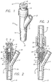
- FIGS. 1 through 3 a Y-connector incorporating a needleless valve embodying the principles of the present invention.
- This particular connector configuration was selected for illustration purposes only as the subject needleless valve can be embodied in any of a variety of connectors including, but not limited to, J-loops, T-Connectors, Tri-connectors, PRN adapters, Luer-locks, slip Luers, tubing engagement devices, access pins, and others.
- the Y-connector 12 comprises a housing 14 terminating in an exit port 20 and having a Y-branch 21 with a Y-branch port 22.
- This particular embodiment also comprises a Luer adapter 16 forming a part of the housing and that adapter includes a connection port 18.
- the adapter is configured to receive all ANSI standard male Luer fittings, as well as other blunt cannulas or fluid conduit devices.
- a piston head 24 located internally to the housing is flush with the surrounding connection port 18 and has a tightly closed orifice 26 at its center.
- FIG. 2 shows in enlarged cross-section the Y-connector of FIG. 1 with the needleless valve in its closed position.
- the Y-branch 21 leads to the Y-branch port 22 and the distal section 19 of the housing 14 extends between the Y-branch and the exit port 20.
- the housing 14 includes a tubular section 28 having a circular cross-section, an exit orifice 30 at its base 31, a support tube 29 extending upwardly from the base, and a groove 32 formed in the base surrounding the support tube.
- the exterior surface of the tubular section 28 near its proximal end is stepped slightly inwardly 34 to receive the Luer adapter 16 thereover and provide ultrasonic weld geometry.
- the adapter and the housing may be joined by a spin weld, snap fit, by bonding, or by other means.
- FIG. 2 additionally shows the piston element 44 in place within the bore 33 of the tubular section 28 captured between the Luer adapter 16 and the base 31.
- the piston element 44 includes a total of four bellows.
- the alternative embodiment illustrated in FIGS. 4 and 5 is similar to the embodiment shown in FIGS. 2 and 3, with the exception that the support tube 29 has been deleted, and the piston element 44a has a total of five bellows of shallower angle.
- the interior of the Luer adapter 16 has sections of various diameters.
- the section directly adjacent the connection port 18 comprises a standard ANSI Luer taper section 38 that incorporates a very slight inward taper.
- the center section 40 has a substantially larger diameter and is separated from the taper section 38 by the tapered ramp/lock section 42. Additionally, the inner diameter of the center section 40 is slightly larger than the inner diameter of the tubular section 28 of the body 14 for reasons discussed below.
- the Luer adapter 16 includes a skirt 36 that is dimensioned to fit over the stepped proximal end 34 of the tubular section 28 to provide ultrasonic weld geometry.
- the adapter 16 may be molded of a material containing a phosphorescent colorant to render the connector visible in a darkened room.
- a resiliently deformable piston element 44 and 44a is captured between the base 31 of the tubular section 28 and the Luer adapter 16 in the bore 33 of the housing 14. While the details of its structure vary slightly from embodiment to embodiment, the views of element 44a shown in FIGS. 7a and 7b serve to illustrate many of the common features.
- the piston element's structure 44a which is molded in its entirety of rubber in this embodiment generally includes a piston 46 and a compressible section 48.
- the piston 46 in turn, includes a piston head 24 that is elliptical in cross-section and a thick taper-lock portion 50 that is circular in cross-section.
- a marquise-shaped bore 51 is formed along the longitudinal axis of the piston head 24 and terminates in an orifice 26 at its proximal end and a taper lip seal 59 at its distal end.
- the taper lip seal 59 comprises a pair of lips 54 that extend from opposed sides of the bore's sides.
- the lips comprise conical sections that extend from the bore s sides to function as a seal.
- the marquise-shaped bore 51 is oriented such that its major axis 53 is perpendicular to the major axis 55 of the elliptically-shaped piston head.
- the transitional section 57 between the piston head 24 and the taper lock portion 50 is elliptical and conical in shape wherein the major axis of such ellipse is parallel to the major axis 55 of the piston head and perpendicular to the major axis 53 of the bore 51. This geometry further assists in naturally biasing the marquise-shaped bore into its open position.
- This elliptical shape creates an outward force parallel to the major axis of the elliptical shaped piston head and an inward force parallel to that same axis.
- the inward force tends to compress the piston in a direction perpendicular to its major axis and thus tends to pull the marquise-shaped bore open when a male Luer applies force to the top of the piston moving the piston into the center section 40 of the adapter 16.
- the taper-lock portion 50 of the piston element 44 is fairly thick in order to prevent it from being compressed. This thicker section helps to hold the piston in the valve at higher internal pressures and also acts as a divider between the spring action below and the opening and closing of the marquise-shaped bore above. Although the piston element 44 is seated in the base 31 of the housing tightly, extreme internal pressures may provide a substantial force to push the piston element 44 out of the housing 14 thereby destroying its integrity. This thickened portion 50 of the piston element provides added assurance that it will not compress under such internal forces and will hold the piston in position in the housing.
- FIGS. 8a and 8b illustrate an alternative embodiment wherein the inner diameter of the tubular section 28 is sufficiently reduced relative the inner diameter of the center section 40 of the adapter 16 to accommodate an annular groove 35 formed in its proximal edge.
- Sections of a circular groove 37 are formed on each end of the major axis 55 of the bottom of the elliptical piston head 24 to provide hooks 25.
- the hooks are configured so as to engage the groove 35 in the tubular section. Once the hooks have engaged the groove as a result of the male Luer 62 pushing the piston 24 farther into the adapter 16, the hooks will oppose further movement of the periphery of the piston and will result in any further male Luer forces causing the bore 51 to open wider, as shown in FIG. 8b.
- FIG. 9 illustrates an alternative embodiment wherein a pair of flexible flaps 55 extend from about the bore 51 to provide a check valve 69. This opposes the back flow of fluid while the piston element is in its closed state.
- the compressible section 48 may comprise an accordioned configuration as shown in FIGS. 2-5, 7a, 7b, and 8a or, alternatively, an annularly or helically ribbed structure that similarly allows for the controlled collapse of the structure along its longitudinal axis to generate a restoring force.
- FIGS. 10a through 10d Some alternative embodiments are illustrated in FIGS. 10a through 10d and show possible variations in the number, size, and configuration of the ribs or bellows.
- Different shapes of the piston element may be used to improve flow rate, activation force, spring return rate, sealing, piston retention, and acceptance of blunt cannulas.
- the piston geometry variations could also improve the valve function with fluids that easily solidify by removing internal annular grooves and pinch point areas. Modifications include changing the number of bellows, ribs, wall thickness, height, diameter, durometer, color, and geometry. Pinch point areas are formed from the accordioned folds that come together upon compression of the piston and could, under certain conditions, trap solidified fluids to interfere with the compression of the piston.
- FIG. 10a shows a compressible section having five bellows as per FIGS. 4, 5, 7, and 8 which require a reduced activation force.
- FIG. 10b shows a compressible section having an external ribbed structure wherein the compressed shape has no pinch points.
- FIG. 10c shows the compressible section of the piston element with straight walls to increase activation force and reduce pinch points.
- FIG. 10d shows a compressible section which provides a smooth interior surface upon compression to increase the flow rate.
- the distal end 45 of the compressible section 48 is received in the groove 32 in the base 31 of the tubular section 28 to form a tight seal about the support tube 29 and the exit orifice 30.
- the piston element is lubricated with FDA approved silicone oil to facilitate movement of the piston within the connector and to prevent the bore 51 through the piston head 24 from being sealed closed during sterilization.
- a support structure in the form of a flattened post 63, has been added to the interior of the tubular section 28 so as to project into the compressible section 48 of the piston 46.
- the post has a rounded tip 61 that extends into the bore 51 of the piston element 24 upon depression of the piston 44 to assist in its opening. Clearance between the post's tip 61 and the pointed ends of the marquise-shaped bore 51 facilitates flow thereby, while clearance between the thinner dimension of the flattened post 63 and the interior surface of the collapsible section 48 allows for the flow of fluid into the exit orifice 30.
- FIGS. 12 and 13 illustrate a further alternative embodiment wherein an extension spring in the form of a diaphragm 64 serves to bias the piston 46 into its closed position, rather than the compression spring approach shown in the other figures.
- the diaphragm 64 extends from the base of the taper lock section 50 and has an annular bead 66 formed about its periphery. Such bead is captured between the Luer adapter 16 and the proximal edge of the tubular section 28. Grooves are formed in these respective elements to ensure a positive grasp of the bead element 66.
- the position of the bead 66 relative its point of attachment to the taper lock section 50, and the sizing of the diaphragm 64 ensure that the diaphragm is pre-loaded such that it biases the tapered shoulder 56 of the piston 46 into contact with the taper lock section 42 of the adapter 16.
- the dimensions of the elliptical piston head 24 and the marquise-shaped bore 51 are selected such that when the head is constrained into the circular interior of the ANSI Luer taper section 38 of the Luer adapter 16, the bore is completely collapsed to tightly close off the orifice 26 and cause the adjacent lips 54 of the taper lip seal 59 to abut one another.
- the tapered shoulder 56 of the taper lock section 50 contacts the ramp/lock section 42 of the adapter 16 and prevents the top of the piston head 24 from extending beyond the connection port 18.
- the internal diameter of the center section 40 of the Luer adapter 16 is selected such that the piston head 24 is free to assume its elliptical shape when positioned therein. This, in turn, allows the bore 51 to reassume its natural marquise-shape thereby opening a fluid path through the piston and the connector.
- the needleless connector is initially in its unaccessed state or closed position as shown in FIG. 2, 4, 11a, and 11b.
- the compressible section 48 is pre-loaded and causes the piston head 24 to be biased into the ANSI Luer taper section 38 (FIG. 6) of the Luer adapter 16.
- the shoulder 56 of the taper-lock section 50 contacts the tapered ramp/lock section 42 of the adapter 16 and prevents the top of the piston head 24 from extending beyond the connection orifice 18 to form a smooth and flush surface.
- the bore 51 throughout the piston head 24 is tightly squeezed shut by virtue of the normally elliptically shaped piston head being constrained into the circular cross-section of the ANSI Luer taper section 38.
- the sharp pointed ends of the marquise-shaped bore facilitate a tight seal upon compression of the bore along its minor axis by compression of the piston head 24 along its major axis.
- the taper lips 54 of the taper lip seal 59 or, alternatively, the flexible flaps 55 of the check valve 69 further ensure that the bore 51 remains sealed even when subjected to substantial internal pressures.
- the diaphragm element 64 employed in the alternative embodiment shown in FIGS. 12 and 13 similarly serves to bias the piston head 24 into the ANSI Luer taper section of adapter 16.
- the piston head 24 and the edge of the connection port 18 are cleaned by, for example, passing a sterilizings wipe over the smooth surface.
- the absence of ridges, grooves, gaps, or protrusions ensure that proper cleanliness is achieved.
- the connector is then ready to be accessed by a standard male Luer with or without a Luer lock.
- the slightly reduced inner diameter of the tubular section 28 relative to the diameter of the center section 40 of the adapter 16 serves to further enlarge the orifice 26 of the bore 51 by forcing rubber material up around the outside of the male tip 60.
- the hooks 25 formed in the bottom edge of the taper lock section 50 engage an annular groove 35 to positively pull the bore 51 open.
- the center section 40 of the Luer adapter 16 may be formed to have an elliptical shape wherein its minor axis is sized slightly smaller than the minor axis of the piston head 24. This serves to compress the piston head along its minor axis further ensuring that the bore attains its fully opened shape.
- the connector In this position, the connector is fully accessed to provide a short, straight, unobstructed fluid path through the connector. At no time does fluid flow about the outside of the piston element on its way through the connector.
- a "residual" volume i.e., the volume between the male Luer and the exit orifice, of as little as 0.04 ml is attainable. Air leakage, or the entry of contamination, as well as the escape of fluid from the device, is precluded at all times.
- the support tube 29, and the center post 63 serve to prevent the compressible section 48 from buckling and closing off the fluid path.
- the flattened cross-sectional shape of the post 63 ensures adequate clearance adjacent the compressed accordioned section 48 to provide for flow at all times.
- fluid is directed through the center of the support tube 29.
- the biasing force generated by the compressible section 48 of the piston element 44, or the stretchable diaphragm 64 of the alternative embodiment shown in FIGS. 12 and 13, maintains contact between the piston head 24 and the male Luer tip 62.
- the slightly larger diameter of the center section 40 of the Luer adapter 16 (FIG. 6) relative to the tubular section 28 causes the piston taper-lock section 50 to freely move into position with the shoulder 56 (FIG. 7a) abutting the ramp/lock section 42 (FIG. 6).
- the elliptical piston head 24 is guided into the ANSI Luer taper section 38 by the tapered ramp/lock section 42 where it is once again forced into the constrained circular shape of the ANSI Luer taper section to close off the bore 51 and reestablish a positive seal.
- a similar operation occurs with the embodiment shown in FIGS. 12 and 13.
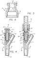
- a medical adapter 100 having a needleless valve section 102 and a sharpened cannula section 104. Also included are two spring clips 106 and 108 on opposite sides of a generally tubular-shaped body member 110. Each spring clip 106 and 108 includes a spring 112, a handle 114, an arm 116, and a claw section 118. At rest, as shown in FIG. 14, the springs 112 are approximately perpendicular to the body 110 and the claws 118 are almost touching. In other embodiments, the springs may be mounted such that they have different angles in relation to the body.
- the arms 116 and the claws 118 are configured so that when the adapter 100 is not installed through a pierceable membrane for fluid flow, the arms and claws cover the sharpened point 120 of the cannula 122 to reduce the likelihood of inadvertent punctures when handling.
- the needleless valve section 102 of the adapter 100 includes the piston head 24 containing an opening 26 (also shown in FIG. 20), as shown and described previously.
- FIG. 15 Shown in FIG. 15 is an application of the adapter of FIG. 14 to a drug vial 124.
- the arms 116 of the adapter are located on either side of the neck 126 of the bottle and the spike 122 has pierced the elastomeric septum 128.
- the operator would press inward on both handles 114 until the claws 118 clear the flange 130 of the bottle opening, and then pierce the septum 128 with the spike, as shown.
- the handles include raised ridges 129 in this embodiment, to assist the operator in pressing the handles inward.
- a needleless connector such as a male Luer taper fitting, may be inserted into the needleless connection port 18 to open the valve created by the piston 44 (not shown) and permit fluid flow. Fluid may be conducted into the vial 124, for mixing purposes for example, and may be conducted out of the vial, into a patient for example.
- the needleless connector port in FIG. 15 also has a male Luer lock fitting.
- the claws are located at an angle to the arms 116 which in this case is 90°. Other angles may be used.
- a bevel 132 is formed on each claw to result in a sharp interior edge and two points 134 (also seen in FIG. 14).
- a circular notch 136 is formed in each claw. Because the radius of the notch would be correct for only one neck size, its primary purpose is to result in the two sharp points 134 on each claw 118 for engaging a variety of devices to hold the connector in place. Secondarily however, the notch may provide a fit with a rounded device of the proper size for even greater surface contact between the claw and the device.
- FIG. 18 shows a cross section of certain elements, the adapter 100 has been engaged with the injection port of a fluid bag.
- the injection site of the fluid bag comprises a thin plastic membrane 139 that the sharpened cannula 122 has penetrated for fluid communication with the interior of the bag and any contents therein.
- the claws 118 have engaged the tubing 138 of the bag due to the action of the springs 112.
- the fluid bag includes a sealing tubing 140 forming a part of the opening of the bag.
- the sealing tubing 140 has been engaged by the adapter 100 in a fluid-tight relationship.
- the body 110 of the adapter includes a taper 142 between the base 144 of the sharpened cannula 122, which has a larger radius than the cannula, and the sealing portion 146 of the body 110.
- the sealing portion 146 has a size selected to provide a tight fit between it and the inner diameter of the sealing tubing 140 of the bag for a fluid-tight seal. Any fluids dripping from the pierced membrane 139 of the bag will not pass the seal created by the sealing portion 146 and the tubing 140. Thus the adapter 100 can be left in position in the sealing tubing 140 for later use.
- the taper 142 on the body 110 assists in guiding the sharpened cannula 122 and the sealing portion 146 into the sealing tubing 140 of the bag for easier engagement. Typically, a twisting motion is used to insert the body 110 fully into the sealing tubing 140 to establish a fluid-tight seal.
- FIG. 19 presents an application of the adapter 100 shown in FIG. 18.
- the solution bag 138 is inverted and hung from a hangar 148.
- the adapter 100 has been inserted and has pierced the thin membrane of the bag as shown in FIG. 18 thus establishing fluid communications with the medical fluid 150 in the bag.
- a syringe 151 has been inserted into the needleless valve section 102 of the adapter 100 for drawing fluid 150 from the bag or inserting fluid into the bag.
- the other port of the bag 138 is connected to a fluid administration set 152 that includes a sharpened cannula (not shown) piercing the bag port, tubing, and a cannula applied to a patient 154.
- a volumetric infusion pump 156 operates on the tubing in a process well known to those skilled in the art to accurately meter the fluid 150 to the patient.
- the infusion pump in this case comprises peristaltic fingers and a pressure plate (not shown) to accurately control the flow of medical fluids through the tubing 152 to the patient.
- the neck of the bag which the claws 118 engage, is formed of a resilient plastic material
- the sharp edge 134 of the claws achieve a grip on the bag.
- there is a substantial amount of friction between the sealing portion 146 and the tubing 140 so that it is unlikely that the adapter 100 will fall out of the bag 138 due to the weight of the syringe 151, even if full.
- the configuration of the claws at an angle to the arms further resists disengagement with the bag because before the adapter 100 could drop off the bag, the claws would likely hit the flange 145 of the bag formed by the membrane 139.
- the spring force will typically be large enough to prohibit the arms from moving outward on their own or in response to the weight of the syringe.
- the length of the springs and the length of the arms are selected so as to successfully engage any device to which the adapter may be used. Because the springs and arms are relatively long, they will successfully engage small as well as large devices. In select applications, the length of each may be reduced, as desired.
- the adapter 100 adapts the pierceable bag membrane to a needleless connection.
- the adapter 100 may be left in place while the bag is connected, disconnected, and reconnected to fluid administration sets 152 as required.
- the adapter 100 is fluid tight with the sealing tubing of the bag and contains an internal and fully integrated needleless valve 102 so that unless a connector is engaged with the adapter 100, no fluid will flow.
- FIG. 20 presents an exploded view of the adapter 100 of FIG. 14.
- the adapter comprises only three parts: a Luer adapter 16; a piston 44; and the sharpened cannula section 158.
- the sharpened cannula section 158 is constructed as one piece and includes the springs, handles, arms, claws, sealing portion, taper, and sharpened cannula.
- the piston 44 is friction fit into the sharpened cannula section 158 as can be seen more clearly in FIG. 18.
- the groove 32 is formed to have a tight fit with the piston 44 to retain the piston.
- a vent 160 is formed in the side wall of the sharpened cannula section 158 to allow air to escape during assembly of the tight fitting piston in the groove 32.
- the proximal end 161 of the sharpened cannula section is ultrasonically welded to the Luer adapter 16 for final assembly of the adapter 100.
- This small number of parts and ease in assembly results in reduced cost for the adapter 100.
- a larger number of parts may be used to construct the adapter.
- the sharpened cannula 122 may be a separate part attached to the base 144. It may be formed of a metallic substance.
- each handle 164 comprises two curved segments located on the sharpened cannula side of the springs for receipt of the operator s fingers or thumb and fingers. The operator would pull on the handles 164 to separate the claws 118.
- a versatile adapter has been disclosed.
- the design of the adapter is such that the sharpened cannula is protected from inadvertent punctures of operators yet can successfully be used to adapt pierceable septa to use with needleless devices.
- Both a sharpened cannula and a needleless connector are included in one adapter thus obviating the need for two separate devices.
- a restrictive, single-sized shroud is not used to protect the sharpened cannula.
- the protective arms in accordance with the invention move out of the way when inserting the sharpened cannula thus permitting the adapter to be used with a wide variety of devices.
- the adapter also obviates the need to stock various sizes of connectors, as the adapter in accordance with the invention is capable of fitting numerous devices of varying sizes.
- the adapter will successfully connect to solution bags, blood tubes, drug vials, Y-sites, and pre-slit and unslit injection sites.
- the length of the sharpened cannula is selected to be longer than the thickest rubber septum or membrane and the lengths of the arms and springs are selected to be long enough to fit over and around all of the above-listed devices.
- the priming volume is significantly reduced and the dead space in the adapter, in which fluid will pool, is also significantly reduced or eliminated. This results in more fluid reaching the patient and less fluid being lost as overhead, or adapter lost fluid.
- a barb or barbs may be added to the sharpened cannula so that the sharpened cannula cannot be removed once inserted into the septum.
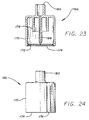
- FIG. 23 and 24 An alternate embodiment of a projected adapter 166 is shown in FIG. 23 and 24.
- a sharpened cannula 168 is disposed within a plurality of protective shrouds.
- the outer shroud 170 is at least as long as the sharpened cannula 168 to protect the cannula from puncturing an operator of the adapter 166.
- a raised ridge 172 is formed near the open end 174 of the outer shroud 170. The raised ridge disposed completely around the inside surface of the outer shroud assists in retaining the adapter in place over a pierceable site. As the shroud is forced over the site, the ridge will also snap over the flange of the site, for example, and will retain the adapter 166 in place.
- FIG. 24 presents an embodiment where an arm 176 has been formed in the outer shroud 170 by forming two slots in the axial direction.
- a raised ridge would be formed on the inside surface of the arm 176 to function in the same way as the ridge in FIG. 23.
- the slots forming the arm are relatively lengthy, the arm can move outward and inward in relation to the shroud 170. Its connection to the shroud acts as a spring urging the arm 176 back to its position level with the shroud 170.
- an inner shroud 178 is concentric with the sharpened cannula 168, as is the outer shroud, and is shorter than the outer shroud.
- the inner diameter of the inner shroud 178 is selected to closely fit with the elastomeric septum provided with the injection port of solution bags. Forcing the elastomeric septum into the inner shroud creates a fluid-tight seal.
- the sharpened cannula is long enough to pierce the plastic membrane of the injection port of a solution bag, shown in FIG. 18, as the elastomeric septum (not shown) seals with the inner shroud.
- the elastomeric septum has been removed from the injection port shown in FIG. 18.
- a female Luer fitting 180 is formed at one end of the adapter.
- a needleless valve may be disposed in the adapter 166 instead of only the female Luer fitting, similar to the configuration shown in FIG. 18.
Abstract
Description
Claims (22)
- A medical adapter for interconnecting a pierceable site with a male fluid connector, comprising:a body having a first end and a second end;a needleless site located at the first end of the body having a fluid flow port;a sharpened cannula located at the second end of the body, the cannula having a sharpened tip;an internal fluid channel interconnecting the fluid flow port of the needleless site with the sharpened cannula so that fluid may flow between the two;a first clip arm mounted to the body, the first clip arm extending to the tip of the sharpened cannula and having a distal end; anda claw at the distal end of the first clip arm facing in the direction of the sharpened cannula and protecting the sharpened tip.
- The medical adapter of claim 1 further comprising a spring connected to the first clip arm to urge the distal end of the first clip arm toward the sharpened tip of the cannula.
- The medical adapter of claim 2 wherein the spring comprises a resilient connecting link attached between the first clip arm and the body.
- The medical adapter of claim 1 wherein the claw comprises a sharpened point facing the sharpened cannula.
- The medical adapter of claim 1 including a sealing portion at said second end of said body, having a size selected to fit within tubing at a pierceable site and create a fluid-tight seal within the tubing, and wherein said claw comprises a sharpened point facing the sharpened cannula;a handle mounted to the first clip arm such that applying force to the handle will cause the claw of the first clip arm to move away from the sharpened cannula tip, anda spring connected to the first clip arm to urge the distal end of the first clip arm towards the sharpened tip of the cannula, wherein the spring comprises a resilient connecting link attached between the first clip arm and the body.
- The medical adapter of claim 1 or claim 5 further comprising:a second clip arm mounted to the body opposite the first arm, the second clip arm extending to the tip of the sharpened cannula and having a distal end; anda claw at the distal end of the second clip arm facing in the direction of the sharpened cannula protecting the sharpened cannula.
- The medical adapter of claim 6 wherein each claw comprises a sharpened surface and two sharp points facing the sharpened cannula.
- The medical adapter of claim 6, wherein each claw comprises a notch facing in the direction of the sharpened cannula.
- The medical adapter of any of claims 1 to 8 further comprising a handle mounted to the first clip arm such that applying force to the handle will cause the claw of the first clip arm to move away from the sharpened cannula tip.
- The medical adapter of claim 6 further comprising a handle mounted to each clip arm such that applying sufficient force to the handles will cause the claws of the clip arms to move away from the sharpened cannula tip.
- The medical adapter of claim 9 or claim 10 wherein the handle is, or the handles are, located so that applying pressure to the or each handle in a direction toward the adapter body will cause the, or the respective, claw to move away from the sharpened cannula tip.
- The medical adapter of claim 11 wherein the or each handle is located so that applying pressure to the or each handle in a direction away from the adapter body will cause the, or the respective, claw to move away from the sharpened cannula tip.
- The medical adapter of any preceding claim wherein the length of the or each clip arm and the or each claw and the angle of the or each claw to the clip arm, or the respective clip arm, are selected so that the or each claw protects the sharpened tip of the cannula to prevent the sharpened tip from piercing an operator of the adapter unless the or each arm and the or each claw are moved away from the sharpened tip.
- The medical adapter of any preceding claim wherein the body comprises a sealing portion at the second end, having a size selected to fit within tubing at a pierceable site and create a fluid-tight seal with the tubing.
- The medical adapter of claim 14 wherein the body further comprises a tapered portion disposed between the sharpened cannula and the sealing portion.
- The medical adapter of any preceding claim wherein the lengths of the sharpened cannula and the clip arm are selected to be long enough to engage pierceable sites of different sizes.
- A medical adapter for interconnecting a pierceable site with a male fluid connector, comprising:a body having a first end and a second end;a female connection site located at the first end of the body, having a fluid flow port;a sharpened cannula located at the second end of the body, the cannula having a sharpened tip;an internal fluid channel interconnecting the fluid flow port of the female connection site with the sharpened cannula so that fluid may flow between the two;a first shroud mounted to the body, and surrounding the sharpened cannula; anda second shroud mounted to the body, and surrounding the sharpened cannula, the second shroud having a length at least as great as the sharpened cannula.
- The medical adapter of claim 17 wherein the second shroud is longer than the first shroud and is located outside the first shroud.
- The medical adapter of claim 17 further comprising a raised ridge formed on an inner surface of one of the shrouds.
- The medical adapter of claim 19 wherein the second shroud is longer than the first shroud and is located outside the first shroud, and the raised ridge is formed on the second shroud.
- The medical adapter of claim 18 wherein the second shroud comprises two elongated notches formed in the shroud to form an arm.
- The medical adapter of claim 21 wherein the arm comprises a raised ridge formed on an inside surface of the arm.
Priority Applications (1)
| Application Number | Priority Date | Filing Date | Title |
|---|---|---|---|
| EP20030028219 EP1398053B1 (en) | 1997-02-02 | 1998-01-27 | Medical adapter having sharpened cannula |
Applications Claiming Priority (2)
| Application Number | Priority Date | Filing Date | Title |
|---|---|---|---|
| US794404 | 1997-02-02 | ||
| US08/794,404 US5839715A (en) | 1995-05-16 | 1997-02-02 | Medical adapter having needleless valve and sharpened cannula |
Related Child Applications (1)
| Application Number | Title | Priority Date | Filing Date |
|---|---|---|---|
| EP20030028219 Division EP1398053B1 (en) | 1997-02-02 | 1998-01-27 | Medical adapter having sharpened cannula |
Publications (3)
| Publication Number | Publication Date |
|---|---|
| EP0856331A2 true EP0856331A2 (en) | 1998-08-05 |
| EP0856331A3 EP0856331A3 (en) | 2000-03-01 |
| EP0856331B1 EP0856331B1 (en) | 2003-12-10 |
Family
ID=25162543
Family Applications (2)
| Application Number | Title | Priority Date | Filing Date |
|---|---|---|---|
| EP20030028219 Expired - Lifetime EP1398053B1 (en) | 1997-02-02 | 1998-01-27 | Medical adapter having sharpened cannula |
| EP19980101414 Expired - Lifetime EP0856331B1 (en) | 1997-02-02 | 1998-01-27 | Medical adapter having needleless valve and sharpened cannula |
Family Applications Before (1)
| Application Number | Title | Priority Date | Filing Date |
|---|---|---|---|
| EP20030028219 Expired - Lifetime EP1398053B1 (en) | 1997-02-02 | 1998-01-27 | Medical adapter having sharpened cannula |
Country Status (12)
| Country | Link |
|---|---|
| US (2) | US5839715A (en) |
| EP (2) | EP1398053B1 (en) |
| JP (1) | JP2984642B2 (en) |
| AU (1) | AU709438B2 (en) |
| CA (1) | CA2227661C (en) |
| DE (3) | DE69837688T2 (en) |
| ES (2) | ES2286376T3 (en) |
| HK (2) | HK1015291A1 (en) |
| NZ (1) | NZ329638A (en) |
| PL (1) | PL188370B1 (en) |
| PT (2) | PT856331E (en) |
| SG (1) | SG60190A1 (en) |
Cited By (60)
| Publication number | Priority date | Publication date | Assignee | Title |
|---|---|---|---|---|
| EP1839699A1 (en) * | 2004-12-22 | 2007-10-03 | Terumo Kabushiki Kaisha | Connector, tube assembly, infusion tube set, and container for medical use |
| EP1930038A2 (en) | 2006-12-08 | 2008-06-11 | Becton, Dickinson and Company, Wagner, Jaconda | Apparatus for delivering a therapeutic substance through an injection port |
| WO2009087572A1 (en) * | 2008-01-09 | 2009-07-16 | Novartis Ag | Unitary withdrawal spike unit suitable for factory fitting |
| FR2931363A1 (en) * | 2008-05-23 | 2009-11-27 | Vygon | Connector i.e. Male Luer Connector, for fluid circuit in medical applications, has distal coupler mounted slidingly with respect to proximal coupler between distal rest position and usage position in which tube is released from membrane |
| EP2189179A1 (en) * | 2003-06-06 | 2010-05-26 | Baxter International Inc. | Method and device for transferring fluid |
| WO2010074871A1 (en) | 2008-12-22 | 2010-07-01 | Baxter International.Inc. | Vial access spike assembly |
| EP2219721A1 (en) * | 2007-12-19 | 2010-08-25 | Kimberly-Clark Worldwide, Inc. | Automatic shut-off connector for enteral feeding devices |
| EP2266523A1 (en) * | 2006-10-16 | 2010-12-29 | Cardinal Health 303, Inc. | Vented vial adapter with filter for aerosol retention |
| WO2011009885A1 (en) * | 2009-07-23 | 2011-01-27 | Angiomed Gmbh & Co. Medizintechnik Kg | Method of joining tubing for use in medical catheters |
| WO2013156994A1 (en) * | 2012-04-17 | 2013-10-24 | Medimop Medical Projects Ltd | Quick release vial adapter |
| US8608723B2 (en) | 2009-11-12 | 2013-12-17 | Medimop Medical Projects Ltd. | Fluid transfer devices with sealing arrangement |
| US8684994B2 (en) | 2010-02-24 | 2014-04-01 | Medimop Medical Projects Ltd. | Fluid transfer assembly with venting arrangement |
| US8752598B2 (en) | 2011-04-17 | 2014-06-17 | Medimop Medical Projects Ltd. | Liquid drug transfer assembly |
| US8753325B2 (en) | 2010-02-24 | 2014-06-17 | Medimop Medical Projects, Ltd. | Liquid drug transfer device with vented vial adapter |
| US8852145B2 (en) | 2010-11-14 | 2014-10-07 | Medimop Medical Projects, Ltd. | Inline liquid drug medical device having rotary flow control member |
| US8905994B1 (en) | 2011-10-11 | 2014-12-09 | Medimop Medical Projects, Ltd. | Valve assembly for use with liquid container and drug vial |
| USD720451S1 (en) | 2012-02-13 | 2014-12-30 | Medimop Medical Projects Ltd. | Liquid drug transfer assembly |
| US8979792B2 (en) | 2009-11-12 | 2015-03-17 | Medimop Medical Projects Ltd. | Inline liquid drug medical devices with linear displaceable sliding flow control member |
| US8998875B2 (en) | 2009-10-01 | 2015-04-07 | Medimop Medical Projects Ltd. | Vial assemblage with vial and pre-attached fluid transfer device |
| WO2015079371A1 (en) * | 2013-11-26 | 2015-06-04 | Nestec S.A. | Adapters for consumable product packages and methods for using same |
| USD734868S1 (en) | 2012-11-27 | 2015-07-21 | Medimop Medical Projects Ltd. | Drug vial adapter with downwardly depending stopper |
| USD737436S1 (en) | 2012-02-13 | 2015-08-25 | Medimop Medical Projects Ltd. | Liquid drug reconstitution assembly |
| US9283324B2 (en) | 2012-04-05 | 2016-03-15 | Medimop Medical Projects, Ltd | Fluid transfer devices having cartridge port with cartridge ejection arrangement |
| US9339438B2 (en) | 2012-09-13 | 2016-05-17 | Medimop Medical Projects Ltd. | Telescopic female drug vial adapter |
| USD757933S1 (en) | 2014-09-11 | 2016-05-31 | Medimop Medical Projects Ltd. | Dual vial adapter assemblage |
| USD765837S1 (en) | 2013-08-07 | 2016-09-06 | Medimop Medical Projects Ltd. | Liquid transfer device with integral vial adapter |
| USD767124S1 (en) | 2013-08-07 | 2016-09-20 | Medimop Medical Projects Ltd. | Liquid transfer device with integral vial adapter |
| US9604184B2 (en) | 2013-03-06 | 2017-03-28 | Orthovita, Inc. | Mixing system and valve assembly |
| WO2017053098A1 (en) * | 2015-09-21 | 2017-03-30 | Carefusion 303, Inc. | Priming device |
| EP2313049B1 (en) | 2008-07-18 | 2017-04-12 | Allpure Technologies, Inc. | Fluid transfer device |
| US9795536B2 (en) | 2012-08-26 | 2017-10-24 | Medimop Medical Projects, Ltd. | Liquid drug transfer devices employing manual rotation for dual flow communication step actuations |
| USD801522S1 (en) | 2015-11-09 | 2017-10-31 | Medimop Medical Projects Ltd. | Fluid transfer assembly |
| US9801786B2 (en) | 2013-04-14 | 2017-10-31 | Medimop Medical Projects Ltd. | Drug container closure for mounting on open-topped drug container to form drug reconstitution assemblage for use with needleless syringe |
| US9839580B2 (en) | 2012-08-26 | 2017-12-12 | Medimop Medical Projects, Ltd. | Liquid drug transfer devices |
| US9943463B2 (en) | 2013-05-10 | 2018-04-17 | West Pharma. Services IL, Ltd. | Medical devices including vial adapter with inline dry drug module |
| USD832430S1 (en) | 2016-11-15 | 2018-10-30 | West Pharma. Services IL, Ltd. | Dual vial adapter assemblage |
| US10278897B2 (en) | 2015-11-25 | 2019-05-07 | West Pharma. Services IL, Ltd. | Dual vial adapter assemblage including drug vial adapter with self-sealing access valve |
| US10285907B2 (en) | 2015-01-05 | 2019-05-14 | West Pharma. Services IL, Ltd. | Dual vial adapter assemblages with quick release drug vial adapter for ensuring correct usage |
| US10357429B2 (en) | 2015-07-16 | 2019-07-23 | West Pharma. Services IL, Ltd. | Liquid drug transfer devices for secure telescopic snap fit on injection vials |
| US10646404B2 (en) | 2016-05-24 | 2020-05-12 | West Pharma. Services IL, Ltd. | Dual vial adapter assemblages including identical twin vial adapters |
| US10688295B2 (en) | 2013-08-07 | 2020-06-23 | West Pharma. Services IL, Ltd. | Liquid transfer devices for use with infusion liquid containers |
| WO2020148748A1 (en) * | 2019-01-18 | 2020-07-23 | West Pharma. Services IL, Ltd. | Liquid transfer devices for use with intravenous (iv) bottles |
| EP3701981A1 (en) * | 2008-08-18 | 2020-09-02 | Calibra Medical LLC | Drug infusion system with reusable and disposable components |
| US10765604B2 (en) | 2016-05-24 | 2020-09-08 | West Pharma. Services IL, Ltd. | Drug vial adapter assemblages including vented drug vial adapter and vented liquid vial adapter |
| US10772798B2 (en) | 2016-12-06 | 2020-09-15 | West Pharma Services Il, Ltd. | Liquid transfer device with integral telescopic vial adapter for use with infusion liquid container and discrete injection vial |
| US10806671B2 (en) | 2016-08-21 | 2020-10-20 | West Pharma. Services IL, Ltd. | Syringe assembly |
| US10806667B2 (en) | 2016-06-06 | 2020-10-20 | West Pharma. Services IL, Ltd. | Fluid transfer devices for filling drug pump cartridges with liquid drug contents |
| USD903864S1 (en) | 2018-06-20 | 2020-12-01 | West Pharma. Services IL, Ltd. | Medication mixing apparatus |
| US10945921B2 (en) | 2017-03-29 | 2021-03-16 | West Pharma. Services IL, Ltd. | User actuated liquid drug transfer devices for use in ready-to-use (RTU) liquid drug transfer assemblages |
| USD917693S1 (en) | 2018-07-06 | 2021-04-27 | West Pharma. Services IL, Ltd. | Medication mixing apparatus |
| US11027062B2 (en) | 2017-12-03 | 2021-06-08 | West Pharma. Services IL, Ltd. | Liquid transfer device with telescopic vial adapter for use with infusion liquid container and discrete injection vial |
| USD923812S1 (en) | 2019-01-16 | 2021-06-29 | West Pharma. Services IL, Ltd. | Medication mixing apparatus |
| USD923782S1 (en) | 2019-01-17 | 2021-06-29 | West Pharma. Services IL, Ltd. | Medication mixing apparatus |
| US20210290486A1 (en) * | 2018-07-13 | 2021-09-23 | Baxalta Incorporated | Female-female adapter |
| WO2021260050A1 (en) * | 2020-06-24 | 2021-12-30 | Cyto365 Ab | A closed-system type female connector, a method for manufacture, and a stopcock having such female connectors |
| USD954253S1 (en) | 2019-04-30 | 2022-06-07 | West Pharma. Services IL, Ltd. | Liquid transfer device |
| USD956958S1 (en) | 2020-07-13 | 2022-07-05 | West Pharma. Services IL, Ltd. | Liquid transfer device |
| IT202100022613A1 (en) * | 2021-08-31 | 2023-03-03 | Sidam Srl | PUNCTURE DEVICE FOR MEDICAL, DIAGNOSTIC AND PHYSIOLOGICAL FLUID CONTAINERS |
| US11642285B2 (en) | 2017-09-29 | 2023-05-09 | West Pharma. Services IL, Ltd. | Dual vial adapter assemblages including twin vented female vial adapters |
| US11918542B2 (en) | 2019-01-31 | 2024-03-05 | West Pharma. Services IL, Ltd. | Liquid transfer device |
Families Citing this family (241)
| Publication number | Priority date | Publication date | Assignee | Title |
|---|---|---|---|---|
| CZ149294A3 (en) * | 1991-12-18 | 1994-11-16 | Icu Medical Inc | Medicinal valve |
| US5810398A (en) | 1992-10-02 | 1998-09-22 | Pall Corporation | Fluid delivery systems and methods and assemblies for making connections |
| US7033339B1 (en) * | 1998-05-29 | 2006-04-25 | Becton Dickinson And Company (Part Interest) | Self sealing luer receiving stopcock |
| IL114960A0 (en) | 1995-03-20 | 1995-12-08 | Medimop Medical Projects Ltd | Flow control device |
| SE509950C2 (en) * | 1995-05-02 | 1999-03-29 | Carmel Pharma Ab | Device for the administration of toxic liquid |
| US5738663A (en) | 1995-12-15 | 1998-04-14 | Icu Medical, Inc. | Medical valve with fluid escape space |
| US6189859B1 (en) * | 1996-08-01 | 2001-02-20 | Faulding Inc. | Indwelling catheter valve |
| US20020013556A1 (en) * | 1996-11-18 | 2002-01-31 | Cote Andrew L. | Swabbable luer-activated valve |
| US7789864B2 (en) * | 1996-11-18 | 2010-09-07 | Nypro Inc. | Luer-activated valve |
| US6245048B1 (en) * | 1996-12-16 | 2001-06-12 | Icu Medical, Inc. | Medical valve with positive flow characteristics |
| EP0956088B1 (en) * | 1996-12-16 | 2010-07-28 | ICU Medical, Inc. | Positive flow valve |
| DE29707410U1 (en) * | 1997-04-24 | 1997-10-16 | Caremed Vertriebsgesellschaft | Catheter valve |
| EP1716885A3 (en) | 1997-05-09 | 2006-11-15 | Pall Corporation | Connector assemblies, fluid systems, and methods for making a connection |
| US6610042B2 (en) | 1997-12-05 | 2003-08-26 | Felton Medical, Inc. | Disposable unit-dose jet-injection syringe for pre-filled and/or transfilled liquid injectable medical drug or vaccine products and method thereof |
| DE29800107U1 (en) * | 1998-01-07 | 1998-03-05 | Braun Melsungen Ag | Hose coupling for a medical transfer system |
| US6113068A (en) | 1998-10-05 | 2000-09-05 | Rymed Technologies | Swabbable needleless injection port system having low reflux |
| US6706022B1 (en) * | 1999-07-27 | 2004-03-16 | Alaris Medical Systems, Inc. | Needleless medical connector with expandable valve mechanism |
| JP3935292B2 (en) * | 1999-09-16 | 2007-06-20 | テルモ株式会社 | connector |
| WO2001026717A1 (en) | 1999-10-11 | 2001-04-19 | Needleless Ventures, Inc. | Universal anti-infectious protector for needleless injectors |
| US6770054B1 (en) | 1999-11-23 | 2004-08-03 | Felton International, Inc. | Injector assembly with driving means and locking means |
| US7887506B1 (en) | 1999-11-23 | 2011-02-15 | Pulse Needlefree Systems, Inc. | Safety mechanism to prevent accidental patient injection and methods of same |
| US6749589B1 (en) | 2000-01-18 | 2004-06-15 | Sterling Medications, Inc. | Subcutaneous injection set for use with a reservoir that has a septum |
| US20020120231A1 (en) * | 2000-01-18 | 2002-08-29 | Douglas Joel S. | Subcutaneous injection set with secondary injection septum |
| US6695817B1 (en) | 2000-07-11 | 2004-02-24 | Icu Medical, Inc. | Medical valve with positive flow characteristics |
| GB2365344A (en) * | 2000-08-04 | 2002-02-20 | Alan David Mogg | Catheter adaptor |
| WO2002034326A2 (en) * | 2000-10-23 | 2002-05-02 | Nypro, Inc. | Anti-drawback medical valve |
| US6936031B2 (en) * | 2000-12-12 | 2005-08-30 | Gambro Dasco S.P.A. | Site for access to the inside of a channel, and corresponding cannula |
| IL157561A0 (en) | 2001-03-04 | 2004-03-28 | Sterling Medivations Inc | Infusion hub assembly and fluid line disconnect system |
| US6656433B2 (en) | 2001-03-07 | 2003-12-02 | Churchill Medical Systems, Inc. | Vial access device for use with various size drug vials |
| US6499428B1 (en) * | 2001-07-31 | 2002-12-31 | Ideal Instruments, Inc. | Quick disconnect, disposable needle and hub assembly |
| US7044441B2 (en) * | 2001-08-10 | 2006-05-16 | Cardinal Health 303, Inc. | Valved male luer connector having sequential valve timing |
| US6964406B2 (en) | 2001-08-10 | 2005-11-15 | Alaris Medical Systems, Inc. | Valved male luer |
| US6745998B2 (en) | 2001-08-10 | 2004-06-08 | Alaris Medical Systems, Inc. | Valved male luer |
| JP2005500142A (en) * | 2001-08-22 | 2005-01-06 | ナイプロ・インク | Medical valve with expansion member |
| US7837658B2 (en) | 2001-11-13 | 2010-11-23 | Nypro Inc. | Anti-drawback medical valve |
| US6802490B2 (en) * | 2001-11-29 | 2004-10-12 | Alaris Medical Systems, Inc. | Needle free medical connector with expanded valve mechanism and method of fluid flow control |
| US6842649B2 (en) | 2001-12-14 | 2005-01-11 | Cardiac Pacemakers, Inc. | Snap-spin lead assembly and method therefor |
| US6985870B2 (en) | 2002-01-11 | 2006-01-10 | Baxter International Inc. | Medication delivery system |
| US6875205B2 (en) * | 2002-02-08 | 2005-04-05 | Alaris Medical Systems, Inc. | Vial adapter having a needle-free valve for use with vial closures of different sizes |
| US8562583B2 (en) | 2002-03-26 | 2013-10-22 | Carmel Pharma Ab | Method and assembly for fluid transfer and drug containment in an infusion system |
| US7744581B2 (en) * | 2002-04-08 | 2010-06-29 | Carmel Pharma Ab | Device and method for mixing medical fluids |
| US7867215B2 (en) | 2002-04-17 | 2011-01-11 | Carmel Pharma Ab | Method and device for fluid transfer in an infusion system |
| ITMI20020819A1 (en) * | 2002-04-18 | 2003-10-20 | Gambro Lundia Ab | CONNECTION ELEMENT AND CONNECTION DEVICE FOR MEDICAL USE PIPES |
| US7244249B2 (en) * | 2002-05-08 | 2007-07-17 | Cardinal Health 303, Inc. | Needle-free medical connector with expandable valve mechanism and method of fluid flow control |
| SE523001C2 (en) | 2002-07-09 | 2004-03-23 | Carmel Pharma Ab | Coupling component for transmitting medical substances, comprises connecting mechanism for releasable connection to second coupling component having further channel for creating coupling, where connecting mechanism is thread |
| US7507226B2 (en) * | 2002-10-22 | 2009-03-24 | Baxter International Inc. | Access port with safety tab and fluid container employing same |
| US7544191B2 (en) * | 2002-10-22 | 2009-06-09 | Baxter International Inc. | Formed, filled, sealed solution container, port and method for establishing flow between the container and an administration set |
| US7942861B2 (en) | 2002-10-22 | 2011-05-17 | Baxter International Inc. | Fluid container with access port and safety cap |
| JP5148107B2 (en) | 2003-01-21 | 2013-02-20 | カルメル ファルマ アクチボラゲット | Needle for piercing the membrane |
| US20040181192A1 (en) * | 2003-03-11 | 2004-09-16 | Cuppy Michael John | Vascular access device and method of using same |
| US6871838B2 (en) * | 2003-04-03 | 2005-03-29 | B. Braun Medical Inc. | Injection port valve |
| CA2529429C (en) | 2003-06-17 | 2009-10-20 | Filtertek Inc. | Fluid handling device and method of making same |
| US7914502B2 (en) | 2003-07-31 | 2011-03-29 | Nypro Inc. | Anti-drawback medical valve |
| JP4558290B2 (en) * | 2003-08-20 | 2010-10-06 | 川澄化学工業株式会社 | Injection device and medical device |
| DE10348016B4 (en) * | 2003-10-15 | 2007-05-03 | Fresenius Kabi Deutschland Gmbh | Connector for medical fluid containing packaging and packaging for medical fluids |
| JP2007512102A (en) | 2003-11-20 | 2007-05-17 | ザ ヘンリー エム. ジャクソン ファウンデーション フォー ザ アドヴァンスメント オブ ミリタリー メディシン, インク. | Portable manual pump for fluid suction |
| JP2007515228A (en) * | 2003-12-18 | 2007-06-14 | ハルキー − ロバーツ コーポレイション | Needle-free access vial |
| HK1077154A2 (en) | 2003-12-30 | 2006-02-03 | Vasogen Ireland Ltd | Valve assembly |
| US6994315B2 (en) | 2004-01-13 | 2006-02-07 | Rymed Technologies, Inc. | Swabbable needle-free injection port valve system with neutral fluid displacement |
| US7530546B2 (en) * | 2004-01-13 | 2009-05-12 | Rymed Technologies, Inc. | Swabbable needle-free injection port valve system with zero fluid displacement |
| IL161660A0 (en) | 2004-04-29 | 2004-09-27 | Medimop Medical Projects Ltd | Liquid drug delivery device |
| EP1761440B1 (en) * | 2004-06-17 | 2010-08-18 | Koninklijke Philips Electronics N.V. | Spout assembly for a fluid reservoir used in a personal care appliance |
| JP4847722B2 (en) * | 2004-07-14 | 2011-12-28 | テルモ株式会社 | Medical tube packaging |
| US7615041B2 (en) * | 2004-07-29 | 2009-11-10 | Boston Scientific Scimed, Inc. | Vial adaptor |
| US8337475B2 (en) | 2004-10-12 | 2012-12-25 | C. R. Bard, Inc. | Corporeal drainage system |
| ATE542564T1 (en) | 2004-11-05 | 2012-02-15 | Icu Medical Inc | MEDICAL CONNECTOR WITH HIGH FLOW CHARACTERISTICS |
| US7651481B2 (en) | 2004-12-30 | 2010-01-26 | CareFusion 303 Inc. | Self-sealing male connector device with collapsible body |
| US7670322B2 (en) | 2005-02-01 | 2010-03-02 | Icu Medical, Inc. | Check valve for medical Y-site |
| US7510545B2 (en) | 2005-02-09 | 2009-03-31 | B. Braun Medical Inc. | Needleless access port valves |
| US7114701B2 (en) | 2005-03-02 | 2006-10-03 | B. Braun Medical, Inc. | Needleless access port valves |
| US20060200072A1 (en) * | 2005-03-02 | 2006-09-07 | Peppel Peter W | Needleless access port valves |
| US8100866B2 (en) * | 2005-03-24 | 2012-01-24 | B. Braun Medical Inc. | Needleless access port valves |
| US7615035B2 (en) | 2005-03-24 | 2009-11-10 | B. Braun Medical Inc. | Needleless access port valves |
| US7314061B2 (en) | 2005-03-25 | 2008-01-01 | B. Braun Medical Inc. | Needleless access port valves |
| US7648491B2 (en) * | 2005-05-13 | 2010-01-19 | Bob Rogers | Medical substance transfer system |
| US7998134B2 (en) | 2007-05-16 | 2011-08-16 | Icu Medical, Inc. | Medical connector |
| US20070088293A1 (en) * | 2005-07-06 | 2007-04-19 | Fangrow Thomas F Jr | Medical connector with closeable male luer |
| EP1909735A1 (en) * | 2005-08-01 | 2008-04-16 | Medimop Medical Projects Ltd. | Liquid drug delivery system |
| ATE529088T1 (en) | 2005-08-11 | 2011-11-15 | Medimop Medical Projects Ltd | TRANSFER DEVICES FOR LIQUID MEDICINAL PRODUCTS FOR FAIL-SAFE CORRECT LATCH CONNECTION ON MEDICAL AMPOULES |
| DE102005038651A1 (en) * | 2005-08-16 | 2007-02-22 | Klaus Pfleiderer | catheter valve |
| US8177772B2 (en) | 2005-09-26 | 2012-05-15 | C. R. Bard, Inc. | Catheter connection systems |
| JP5438322B2 (en) * | 2005-10-20 | 2014-03-12 | リッチモンド、フランク、エム. | Conversion device |
| DK1957028T3 (en) * | 2005-10-30 | 2017-09-11 | Medimop Medical Projects Ltd | Needleless additive control valve |
| JP4769113B2 (en) * | 2005-12-02 | 2011-09-07 | 日本シャーウッド株式会社 | connector |
| US7849574B2 (en) * | 2005-12-07 | 2010-12-14 | Honda Motor Co., Ltd. | Device and method for locking together the shafts of an automatic transmission during installation of shaft retaining nuts |
| US20070202186A1 (en) | 2006-02-22 | 2007-08-30 | Iscience Interventional Corporation | Apparatus and formulations for suprachoroidal drug delivery |
| JP4769103B2 (en) * | 2006-03-17 | 2011-09-07 | 日本シャーウッド株式会社 | connector |
| US8002755B2 (en) | 2006-04-11 | 2011-08-23 | Nypro Inc. | Anti-drawback medical valve and method |
| US8292594B2 (en) | 2006-04-14 | 2012-10-23 | Deka Products Limited Partnership | Fluid pumping systems, devices and methods |
| US10537671B2 (en) | 2006-04-14 | 2020-01-21 | Deka Products Limited Partnership | Automated control mechanisms in a hemodialysis apparatus |
| US7867204B2 (en) | 2006-05-04 | 2011-01-11 | B. Braun Medical Inc. | Needleless access port valves |
| US9259535B2 (en) | 2006-06-22 | 2016-02-16 | Excelsior Medical Corporation | Antiseptic cap equipped syringe |
| US11229746B2 (en) | 2006-06-22 | 2022-01-25 | Excelsior Medical Corporation | Antiseptic cap |
| EP2049194A1 (en) | 2006-08-11 | 2009-04-22 | Nypro Inc. | Medical valve with expandable member |
| US20100269932A1 (en) * | 2006-08-17 | 2010-10-28 | Richmond Frank M | Resealable Components And Systems |
| WO2008052140A2 (en) | 2006-10-25 | 2008-05-02 | Icu Medical, Inc. | Medical connector |
| US20080128647A1 (en) * | 2006-12-05 | 2008-06-05 | Humitek, Inc. | Valves and valve assemblies for fluid ports |
| US20080128646A1 (en) * | 2006-12-05 | 2008-06-05 | Humitek, Inc. | Splines and caps for fluid ports |
| US8042563B2 (en) | 2007-02-27 | 2011-10-25 | Deka Products Limited Partnership | Cassette system integrated apparatus |
| US20080253911A1 (en) | 2007-02-27 | 2008-10-16 | Deka Products Limited Partnership | Pumping Cassette |
| US8393690B2 (en) | 2007-02-27 | 2013-03-12 | Deka Products Limited Partnership | Enclosure for a portable hemodialysis system |
| US8562834B2 (en) | 2007-02-27 | 2013-10-22 | Deka Products Limited Partnership | Modular assembly for a portable hemodialysis system |
| US9028691B2 (en) | 2007-02-27 | 2015-05-12 | Deka Products Limited Partnership | Blood circuit assembly for a hemodialysis system |
| KR101861192B1 (en) | 2007-02-27 | 2018-05-28 | 데카 프로덕츠 리미티드 파트너쉽 | Hemodialysis apparatus and methods |
| US8409441B2 (en) | 2007-02-27 | 2013-04-02 | Deka Products Limited Partnership | Blood treatment systems and methods |
| US8425471B2 (en) * | 2007-02-27 | 2013-04-23 | Deka Products Limited Partnership | Reagent supply for a hemodialysis system |
| US20090107335A1 (en) | 2007-02-27 | 2009-04-30 | Deka Products Limited Partnership | Air trap for a medical infusion device |
| US8357298B2 (en) | 2007-02-27 | 2013-01-22 | Deka Products Limited Partnership | Hemodialysis systems and methods |
| US8491184B2 (en) | 2007-02-27 | 2013-07-23 | Deka Products Limited Partnership | Sensor apparatus systems, devices and methods |
| US7942860B2 (en) | 2007-03-16 | 2011-05-17 | Carmel Pharma Ab | Piercing member protection device |
| IL182605A0 (en) | 2007-04-17 | 2007-07-24 | Medimop Medical Projects Ltd | Fluid control device with manually depressed actuator |
| US7975733B2 (en) | 2007-05-08 | 2011-07-12 | Carmel Pharma Ab | Fluid transfer device |
| US8597237B2 (en) | 2007-05-18 | 2013-12-03 | Carefusion 303, Inc. | Universal needlefree bag access device |
| JP5290630B2 (en) | 2007-06-05 | 2013-09-18 | ニプロ株式会社 | Medical connector and manufacturing method thereof |
| US8029747B2 (en) | 2007-06-13 | 2011-10-04 | Carmel Pharma Ab | Pressure equalizing device, receptacle and method |
| US8622985B2 (en) | 2007-06-13 | 2014-01-07 | Carmel Pharma Ab | Arrangement for use with a medical device |
| US8657803B2 (en) | 2007-06-13 | 2014-02-25 | Carmel Pharma Ab | Device for providing fluid to a receptacle |
| US10398834B2 (en) | 2007-08-30 | 2019-09-03 | Carmel Pharma Ab | Device, sealing member and fluid container |
| US8287513B2 (en) | 2007-09-11 | 2012-10-16 | Carmel Pharma Ab | Piercing member protection device |
| JP2010538744A (en) | 2007-09-18 | 2010-12-16 | メディモップ・メディカル・プロジェクツ・リミテッド | Drug mixing injection device |
| IL186290A0 (en) | 2007-09-25 | 2008-01-20 | Medimop Medical Projects Ltd | Liquid drug delivery devices for use with syringe having widened distal tip |
| KR20210000735A (en) * | 2007-10-12 | 2021-01-05 | 데카 프로덕츠 리미티드 파트너쉽 | Apparatus and method for hemodialysis |
| US20090105684A1 (en) * | 2007-10-23 | 2009-04-23 | Baxter International Inc. | Medication port for medical fluid container |
| DK2254542T3 (en) * | 2008-02-18 | 2012-10-15 | Icu Medical Inc | bottle Adapter |
| US8075550B2 (en) | 2008-07-01 | 2011-12-13 | Carmel Pharma Ab | Piercing member protection device |
| US8480645B1 (en) * | 2008-08-22 | 2013-07-09 | Sambhu N. Choudhury | Multi-dose device for insertion into a vial and method of using the same |
| US8888758B2 (en) | 2008-09-05 | 2014-11-18 | Carefusion 303, Inc. | Closed male luer device for minimizing leakage during connection and disconnection |
| US8145652B2 (en) * | 2008-10-09 | 2012-03-27 | International Business Machines Corporation | Automated propagation of non-conflicting queries in distributed databases |
| US9078992B2 (en) | 2008-10-27 | 2015-07-14 | Pursuit Vascular, Inc. | Medical device for applying antimicrobial to proximal end of catheter |
| US9849276B2 (en) | 2011-07-12 | 2017-12-26 | Pursuit Vascular, Inc. | Method of delivering antimicrobial to a catheter |
| EP2351548B1 (en) | 2008-11-21 | 2016-01-27 | Terumo Kabushiki Kaisha | Connector |
| US8790330B2 (en) | 2008-12-15 | 2014-07-29 | Carmel Pharma Ab | Connection arrangement and method for connecting a medical device to the improved connection arrangement |
| US8523838B2 (en) | 2008-12-15 | 2013-09-03 | Carmel Pharma Ab | Connector device |
| US9168366B2 (en) | 2008-12-19 | 2015-10-27 | Icu Medical, Inc. | Medical connector with closeable luer connector |
| US8679090B2 (en) * | 2008-12-19 | 2014-03-25 | Icu Medical, Inc. | Medical connector with closeable luer connector |
| CA2649160A1 (en) * | 2009-01-09 | 2010-07-09 | Duoject Medical Systems Inc. | Fluid transfer device |
| US8864725B2 (en) | 2009-03-17 | 2014-10-21 | Baxter Corporation Englewood | Hazardous drug handling system, apparatus and method |
| JP6017955B2 (en) * | 2009-03-22 | 2016-11-09 | エルカム メディカル アグリカルチュラル コーオペラティブ アソシエーション リミテッド | Closed male luer connector |
| US8454579B2 (en) | 2009-03-25 | 2013-06-04 | Icu Medical, Inc. | Medical connector with automatic valves and volume regulator |
| USD641080S1 (en) | 2009-03-31 | 2011-07-05 | Medimop Medical Projects Ltd. | Medical device having syringe port with locking mechanism |
| US8057095B2 (en) * | 2009-04-23 | 2011-11-15 | Medtronic, Inc. | Multiple use temperature monitor adapter, system and method of using same |
| US8568371B2 (en) | 2009-06-22 | 2013-10-29 | Np Medical Inc. | Medical valve with improved back-pressure sealing |
| EP2456355B1 (en) * | 2009-07-20 | 2016-09-14 | Optiscan Biomedical Corporation | Adjustable connector and dead space reduction |
| US8731639B2 (en) | 2009-07-20 | 2014-05-20 | Optiscan Biomedical Corporation | Adjustable connector, improved fluid flow and reduced clotting risk |
| USD630732S1 (en) | 2009-09-29 | 2011-01-11 | Medimop Medical Projects Ltd. | Vial adapter with female connector |
| CN102821798A (en) | 2009-10-30 | 2012-12-12 | 德卡产品有限公司 | Apparatus and method for detecting disconnection of an intravascular access device |
| USD637713S1 (en) | 2009-11-20 | 2011-05-10 | Carmel Pharma Ab | Medical device adaptor |
| US8480646B2 (en) | 2009-11-20 | 2013-07-09 | Carmel Pharma Ab | Medical device connector |
| US9568113B2 (en) | 2010-01-15 | 2017-02-14 | Allpure Technologies, Llc | Fluid transfer device |
| US8322091B2 (en) * | 2010-02-09 | 2012-12-04 | Atwood Mobile Products, Llc | Window frame assembly with integral seals |
| USD644731S1 (en) | 2010-03-23 | 2011-09-06 | Icu Medical, Inc. | Medical connector |
| JP6058530B2 (en) | 2010-05-06 | 2017-01-11 | アイシーユー・メディカル・インコーポレーテッド | Medical connectors including sealable luer connectors |
| US8758306B2 (en) | 2010-05-17 | 2014-06-24 | Icu Medical, Inc. | Medical connectors and methods of use |
| US9168203B2 (en) | 2010-05-21 | 2015-10-27 | Carmel Pharma Ab | Connectors for fluid containers |
| US8162013B2 (en) | 2010-05-21 | 2012-04-24 | Tobias Rosenquist | Connectors for fluid containers |
| US9138572B2 (en) | 2010-06-24 | 2015-09-22 | Np Medical Inc. | Medical valve with fluid volume alteration |
| US8652104B2 (en) | 2010-06-25 | 2014-02-18 | Smiths Medical Asd, Inc. | Catheter assembly with seal member |
| US9545495B2 (en) | 2010-06-25 | 2017-01-17 | Smiths Medical Asd, Inc. | Catheter assembly with seal member |
| US8454059B2 (en) | 2010-09-13 | 2013-06-04 | Pall Corporation | Connector assemblies, fluid systems including connector assemblies, and procedures for making fluid connections |
| RS54849B1 (en) * | 2010-10-12 | 2016-10-31 | Codan Holding Gmbh | Medical valve assembly |
| USD669980S1 (en) | 2010-10-15 | 2012-10-30 | Medimop Medical Projects Ltd. | Vented vial adapter |
| US20120153201A1 (en) * | 2010-12-21 | 2012-06-21 | Amsino International, Inc. | Luer access valve |
| CN103648549B (en) * | 2011-05-06 | 2016-09-14 | 赛诺菲-安万特德国有限公司 | To re-using protection by disposal type parts |
| WO2012162259A2 (en) | 2011-05-20 | 2012-11-29 | Excelsior Medical Corporation | Caps for cannula access devices |
| US10166381B2 (en) | 2011-05-23 | 2019-01-01 | Excelsior Medical Corporation | Antiseptic cap |
| AU2012259459B2 (en) | 2011-05-24 | 2016-06-02 | Deka Products Limited Partnership | Blood treatment systems and methods |
| US9724458B2 (en) | 2011-05-24 | 2017-08-08 | Deka Products Limited Partnership | Hemodialysis system |
| WO2013000463A1 (en) * | 2011-06-28 | 2013-01-03 | Safeair Ag | An electrosurgical instrument and electrosurgical conductive electrode for use with the instrument |
| US9220660B2 (en) * | 2011-07-15 | 2015-12-29 | Antares Pharma, Inc. | Liquid-transfer adapter beveled spike |
| EP3760275A1 (en) | 2011-09-09 | 2021-01-06 | ICU Medical, Inc. | Medical connectors with fluid-resistant mating interfaces |
| USD674088S1 (en) | 2012-02-13 | 2013-01-08 | Medimop Medical Projects Ltd. | Vial adapter |
| EP3974018A1 (en) * | 2012-03-07 | 2022-03-30 | DEKA Products Limited Partnership | Infusion pump assembly |
| DE102012205490A1 (en) * | 2012-04-03 | 2013-10-10 | Parker Hannifin Manufacturing Germany GmbH & Co. KG | connecting element |
| US9085399B2 (en) * | 2012-05-21 | 2015-07-21 | The Coca-Cola Company | Bag in box cleanable connector system |
| US9162806B2 (en) * | 2012-05-21 | 2015-10-20 | The Coca-Cola Company | Bag in box cleanable connector system having conical plunger |
| US9302090B2 (en) | 2012-07-25 | 2016-04-05 | Applied Medical Technology, Inc. | Photoluminescent coupling |
| CA2887068A1 (en) | 2012-10-15 | 2014-04-24 | Smiths Medical Asd, Inc. | Infusion system disposable alignment system |
| JP5996397B2 (en) * | 2012-11-23 | 2016-09-21 | 東芝メディカルシステムズ株式会社 | Puncture adapter and ultrasound probe |
| WO2014081008A1 (en) * | 2012-11-23 | 2014-05-30 | 株式会社 東芝 | Paracentesis adapter and ultrasonic probe |
| CA2909190C (en) | 2013-04-15 | 2018-10-30 | Becton, Dickinson And Company | Biological fluid sampling transfer device and biological fluid separation and testing system |
| WO2014172238A1 (en) | 2013-04-15 | 2014-10-23 | Becton, Dickinson And Company | Biological fluid collection device and biological fluid separation and testing system |
| US9597028B2 (en) | 2013-04-15 | 2017-03-21 | Becton, Dickinson And Company | Biological fluid collection device and biological fluid separation and testing system |
| BR112015026262B1 (en) | 2013-04-15 | 2022-10-18 | Becton, Dickinson And Company | BIOLOGICAL FLUID SAMPLING TRANSFER DEVICE AND BIOLOGICAL FLUID SEPARATION AND TESTING SYSTEM |
| CA2909227C (en) | 2013-04-15 | 2020-09-08 | Becton, Dickinson And Company | Biological fluid transfer device and biological fluid sampling system |
| WO2014172242A1 (en) | 2013-04-15 | 2014-10-23 | Becton, Dickinson And Company | Blood sampling transfer device and blood separation and testing system |
| CA2909359C (en) | 2013-04-15 | 2018-07-10 | Becton, Dickinson And Company | Biological fluid collection device and biological fluid separation and testing system |
| MX368995B (en) | 2013-04-15 | 2019-10-23 | Becton Dickinson Co | Biological fluid separation device and biological fluid separation and testing system. |
| MX365092B (en) | 2013-04-15 | 2019-05-22 | Becton Dickinson Co | Biological fluid separation device and biological fluid separation and testing system. |
| US9380972B2 (en) * | 2013-04-15 | 2016-07-05 | Becton, Dickinson And Company | Biological fluid collection device and biological fluid collection and testing system |
| ES2832756T3 (en) * | 2013-04-15 | 2021-06-11 | Becton Dickinson Co | Biological fluid sampling device |
| WO2014172232A1 (en) | 2013-04-15 | 2014-10-23 | Becton, Dickinson And Company | Medical device for collection of a biological sample |
| JP6247380B2 (en) | 2013-04-15 | 2017-12-13 | ベクトン・ディキンソン・アンド・カンパニーBecton, Dickinson And Company | Blood collection and transportation device |
| EP2986221B1 (en) | 2013-04-15 | 2019-02-27 | Becton, Dickinson and Company | Biological fluid sampling device |
| CN105246529B (en) | 2013-05-03 | 2019-06-14 | 科尼尔赛德生物医学公司 | Device and method for ocular injection |
| ITTO20130411A1 (en) * | 2013-05-23 | 2014-11-24 | Borla Ind | CANNULA WITH LOCKING DEVICE FOR MEDICAL LINES |
| WO2015003141A1 (en) * | 2013-07-03 | 2015-01-08 | Deka Products Limited Partnership | Fluid connector assembly |
| US10286203B2 (en) * | 2013-08-21 | 2019-05-14 | Cedic S.R. L. | Needlefree valve device |
| ES2941891T3 (en) | 2013-12-11 | 2023-05-26 | Icu Medical Inc | Retention valve |
| AU2015252808B2 (en) | 2014-05-02 | 2019-02-21 | Excelsior Medical Corporation | Strip package for antiseptic cap |
| US11628288B1 (en) | 2014-07-14 | 2023-04-18 | Merit Medical Systems, Inc. | Disinfecting cap for needleless injection sites |
| US10173044B2 (en) * | 2014-09-19 | 2019-01-08 | TA Instruments—Waters L.L.C. | Locking taper fluid connection interfaces |
| US10105529B2 (en) * | 2014-11-12 | 2018-10-23 | Rymed Technologies, Llc | Needleless, intermittent, neutral displacement IV injection port |
| EP3223902B1 (en) | 2014-11-24 | 2021-11-10 | Merit Medical Systems, Inc. | Disinfecting cap for medical connectors |
| US9987420B2 (en) * | 2014-11-26 | 2018-06-05 | Medtronic Minimed, Inc. | Systems and methods for fluid infusion device with automatic reservoir fill |
| US10195341B2 (en) | 2014-11-26 | 2019-02-05 | Medtronic Minimed, Inc. | Systems and methods for fluid infusion device with automatic reservoir fill |
| USD786427S1 (en) | 2014-12-03 | 2017-05-09 | Icu Medical, Inc. | Fluid manifold |
| USD793551S1 (en) | 2014-12-03 | 2017-08-01 | Icu Medical, Inc. | Fluid manifold |
| EP3259014A1 (en) * | 2015-02-20 | 2017-12-27 | Cendres + Métaux SA | Valve device, removing tool and mounting tool |
| US9682189B2 (en) | 2015-02-27 | 2017-06-20 | Carefusion 2200, Inc. | Smart check valve |
| IL237788B (en) * | 2015-03-16 | 2019-10-31 | Kriheli Marino | Septum holders for use in syringe connectors |
| JP6776225B2 (en) | 2015-03-27 | 2020-10-28 | テルモ株式会社 | Medical connector |
| JP2016187446A (en) * | 2015-03-30 | 2016-11-04 | テルモ株式会社 | Bottle needle for infusion container |
| EP3294404A4 (en) | 2015-05-08 | 2018-11-14 | ICU Medical, Inc. | Medical connectors configured to receive emitters of therapeutic agents |
| US11318287B2 (en) * | 2015-06-10 | 2022-05-03 | B. Braun Melsungen Ag | Catheter hub with flexible extended fluid connector and related methods |
| US9987479B2 (en) * | 2015-07-09 | 2018-06-05 | Carefusion 303, Inc. | Closed male luer device for use with needleless access devices |
| WO2017075507A1 (en) * | 2015-10-30 | 2017-05-04 | ECMOtek, LLC | Devices for endovascular access through extracorporeal life support circuits |
| US10507281B2 (en) * | 2016-03-28 | 2019-12-17 | Becton, Dickinson And Company | Cannula capture mechanism |
| JP7066642B2 (en) | 2016-07-18 | 2022-05-13 | メリット・メディカル・システムズ・インコーポレイテッド | Inflatable radial artery compression device |
| ES2929769T3 (en) | 2016-10-14 | 2022-12-01 | Icu Medical Inc | Disinfectant caps for medical connectors |
| US10596532B2 (en) * | 2016-11-16 | 2020-03-24 | Zyno Medical, Llc | Isolatable automatic drug compounding system |
| EP3573699B1 (en) | 2017-01-27 | 2022-08-10 | Merit Medical Systems, Inc. | Disinfecting luer cap and method of use |
| KR20230129611A (en) * | 2017-03-21 | 2023-09-08 | 벨라노 바스큘라, 인크. | Devices and methods for fluid transfer through a placed peripheral intravenous catheter |
| US9975753B1 (en) | 2017-04-26 | 2018-05-22 | Sartorius Stedim North America Inc. | Detachable fluid transfer device accessory and a fluid transfer assembly |
| WO2018204206A2 (en) | 2017-05-01 | 2018-11-08 | Icu Medical, Inc. | Medical fluid connectors and methods for providing additives in medical fluid lines |
| WO2018237090A1 (en) * | 2017-06-21 | 2018-12-27 | Icu Medical, Inc. | Priming cap |
| EP3691741A4 (en) * | 2017-10-04 | 2021-07-28 | Merit Medical Systems, Inc. | Disinfecting cap for valved connectors and method of use |
| CN116549772A (en) * | 2017-11-30 | 2023-08-08 | 威蓝诺血管股份有限公司 | Stable connector device for vascular access and method of use thereof |
| US10709475B2 (en) | 2018-03-07 | 2020-07-14 | Edward J. Mikol | Pumping surgical cannula |
| TWI645871B (en) * | 2018-03-19 | 2019-01-01 | 蔡溪進 | Infusion closed connector for preventing leakage of medical fluid or body fluid |
| US11534595B2 (en) | 2018-11-07 | 2022-12-27 | Icu Medical, Inc. | Device for delivering an antimicrobial composition into an infusion device |
| US11541221B2 (en) | 2018-11-07 | 2023-01-03 | Icu Medical, Inc. | Tubing set with antimicrobial properties |
| US11541220B2 (en) | 2018-11-07 | 2023-01-03 | Icu Medical, Inc. | Needleless connector with antimicrobial properties |
| US11400195B2 (en) | 2018-11-07 | 2022-08-02 | Icu Medical, Inc. | Peritoneal dialysis transfer set with antimicrobial properties |
| US11517732B2 (en) | 2018-11-07 | 2022-12-06 | Icu Medical, Inc. | Syringe with antimicrobial properties |
| US11433215B2 (en) | 2018-11-21 | 2022-09-06 | Icu Medical, Inc. | Antimicrobial device comprising a cap with ring and insert |
| USD957630S1 (en) | 2019-05-20 | 2022-07-12 | Icu Medical, Inc. | Port retention clip |
| USD931441S1 (en) | 2019-05-20 | 2021-09-21 | Icu Medical, Inc. | Port retention clip |
| USD930824S1 (en) | 2019-05-20 | 2021-09-14 | Icu Medical, Inc. | Port retention clip |
| US11690787B2 (en) * | 2020-08-25 | 2023-07-04 | Becton, Dickinson And Company | Drug transfer adapter |
| US11674614B2 (en) | 2020-10-09 | 2023-06-13 | Icu Medical, Inc. | Fluid transfer device and method of use for same |
| AU2021396147A1 (en) | 2020-12-07 | 2023-06-29 | Icu Medical, Inc. | Peritoneal dialysis caps, systems and methods |
Family Cites Families (36)
| Publication number | Priority date | Publication date | Assignee | Title |
|---|---|---|---|---|
| US35841A (en) * | 1862-07-08 | Improvement in chamber-buckets | ||
| FR398137A (en) * | 1908-11-17 | 1909-05-27 | Miguel Becerro De Bengoa | Automatic physiological saline injector |
| US1253309A (en) * | 1917-05-01 | 1918-01-15 | Nels Ulleland | Quick-acting hose-coupling. |
| FR1334267A (en) * | 1962-09-25 | 1963-08-02 | Gaskell & Chambers Ltd | Improvement of valves for barrels or containers for drinks or other liquids |
| DE2949865C2 (en) * | 1979-12-12 | 1985-04-18 | B. Braun Melsungen Ag, 3508 Melsungen | Hose connection for medical devices |
| US4311137A (en) * | 1980-04-30 | 1982-01-19 | Sherwood Medical Industries Inc. | Infusion device |
| US4425122A (en) * | 1981-11-09 | 1984-01-10 | Cohen Milton J | Parenteral apparatus |
| US4752292A (en) * | 1983-01-24 | 1988-06-21 | Icu Medical, Inc. | Medical connector |
| US5344414A (en) * | 1983-01-24 | 1994-09-06 | Icu Medical Inc. | Medical connector |
| US5330450A (en) * | 1983-01-24 | 1994-07-19 | Icu Medical, Inc. | Medical connector |
| DE3303718C1 (en) * | 1983-02-04 | 1984-10-04 | B. Braun Melsungen Ag, 3508 Melsungen | Injection valve for puncture implements or infusion devices |
| US5251873B1 (en) * | 1992-06-04 | 1995-05-02 | Vernay Laboratories | Medical coupling site. |
| US5295658A (en) * | 1987-04-27 | 1994-03-22 | Vernay Laboratories, Inc. | Medical coupling site including slit reinforcing members |
| DE3732515A1 (en) * | 1987-09-26 | 1989-04-06 | Joka Kathetertechnik Gmbh | DEVICE FOR INJECTING AND / OR REMOVING LIQUIDS |
| US5100394A (en) * | 1988-01-25 | 1992-03-31 | Baxter International Inc. | Pre-slit injection site |
| CA1335167C (en) * | 1988-01-25 | 1995-04-11 | Steven C. Jepson | Pre-slit injection site and associated cannula |
| US4981469A (en) * | 1988-04-18 | 1991-01-01 | Dij Catheter Corp. | Septum adapter assembly and external needle adapter fitting |
| US5064416A (en) * | 1988-05-26 | 1991-11-12 | Newgard Kent W | Self-occluding intravascular cannula assembly |
| US4874377A (en) * | 1988-05-26 | 1989-10-17 | Davis Newgard Revocable Family Living Trust | Self-occluding intravascular cannula assembly |
| EP0453264A1 (en) * | 1990-04-17 | 1991-10-23 | Lynn, Lawrence A. | Medical connector |
| JPH04223808A (en) * | 1990-04-19 | 1992-08-13 | Sumitomo Electric Ind Ltd | Silicon nitride sintered body tool |
| US5122123A (en) * | 1991-01-30 | 1992-06-16 | Vaillancourt Vincent L | Closed system connector assembly |
| US5120324A (en) * | 1991-02-22 | 1992-06-09 | Block Medical, Inc. | Protected IV needle injection site coupling |
| US5188610A (en) * | 1991-10-18 | 1993-02-23 | Vetrisystems, Inc. | Fluid dispensing apparatus |
| GB9208713D0 (en) * | 1992-04-22 | 1992-06-10 | Wyeth John & Brother Ltd | Fluid container and connection component |
| US5603706A (en) * | 1992-09-29 | 1997-02-18 | Wyatt; Philip | Infusion apparatus |
| US5356396A (en) * | 1992-09-29 | 1994-10-18 | Medical Associates Network Inc. | Infusion apparatus |
| US5338313A (en) * | 1992-12-17 | 1994-08-16 | Thomas J. Fogarty, M.D. | Adjustable valve having a radially compressible sealing body |
| US5806831A (en) * | 1993-10-13 | 1998-09-15 | Paradis; Joseph R. | Control of fluid flow with internal cannula |
| US5699821A (en) * | 1993-10-13 | 1997-12-23 | Paradis; Joseph R. | Control of fluid flow |
| US5509433A (en) * | 1993-10-13 | 1996-04-23 | Paradis; Joseph R. | Control of fluid flow |
| US5401245A (en) * | 1993-11-26 | 1995-03-28 | Haining; Michael L. | Medical connector with valve |
| US5820601A (en) * | 1994-06-20 | 1998-10-13 | Critical Device Corporation | Needleless injection site |
| US5616130A (en) * | 1994-06-20 | 1997-04-01 | Nima Enterprises, Inc. | Needleless injection site |
| US5470319A (en) * | 1994-06-20 | 1995-11-28 | Critical Device Corporation | Needleless injection site |
| NZ286445A (en) * | 1995-05-16 | 1997-12-19 | Ivac Corp | Needleless luer connector: deformable piston occludes bore |
-
1997
- 1997-02-02 US US08/794,404 patent/US5839715A/en not_active Expired - Lifetime
-
1998
- 1998-01-21 CA CA 2227661 patent/CA2227661C/en not_active Expired - Lifetime
- 1998-01-26 NZ NZ329638A patent/NZ329638A/en not_active IP Right Cessation
- 1998-01-27 EP EP20030028219 patent/EP1398053B1/en not_active Expired - Lifetime
- 1998-01-27 DE DE1998637688 patent/DE69837688T2/en not_active Expired - Lifetime
- 1998-01-27 SG SG1998000210A patent/SG60190A1/en unknown
- 1998-01-27 DE DE1998620311 patent/DE69820311T2/en not_active Expired - Lifetime
- 1998-01-27 EP EP19980101414 patent/EP0856331B1/en not_active Expired - Lifetime
- 1998-01-27 PT PT98101414T patent/PT856331E/en unknown
- 1998-01-27 PT PT03028219T patent/PT1398053E/en unknown
- 1998-01-27 DE DE1998101414 patent/DE856331T1/en active Pending
- 1998-01-27 ES ES03028219T patent/ES2286376T3/en not_active Expired - Lifetime
- 1998-01-27 ES ES98101414T patent/ES2123488T3/en not_active Expired - Lifetime
- 1998-02-02 AU AU52875/98A patent/AU709438B2/en not_active Expired
- 1998-02-02 JP JP2103198A patent/JP2984642B2/en not_active Ceased
- 1998-02-02 PL PL98324599A patent/PL188370B1/en unknown
- 1998-11-20 US US09/197,017 patent/US6142446A/en not_active Expired - Lifetime
-
1999
- 1999-01-27 HK HK99100357A patent/HK1015291A1/en not_active IP Right Cessation
-
2004
- 2004-09-08 HK HK04106819A patent/HK1064059A1/en not_active IP Right Cessation
Non-Patent Citations (1)
| Title |
|---|
| None |
Cited By (83)
| Publication number | Priority date | Publication date | Assignee | Title |
|---|---|---|---|---|
| EP2189179A1 (en) * | 2003-06-06 | 2010-05-26 | Baxter International Inc. | Method and device for transferring fluid |
| EP1839699A4 (en) * | 2004-12-22 | 2008-03-19 | Terumo Corp | Connector, tube assembly, infusion tube set, and container for medical use |
| EP1839699A1 (en) * | 2004-12-22 | 2007-10-03 | Terumo Kabushiki Kaisha | Connector, tube assembly, infusion tube set, and container for medical use |
| RU2469696C2 (en) * | 2006-10-16 | 2012-12-20 | Кэафьюжн 303, Инк. | Vented vial adapter provided with aerosol entrapment filter |
| EP2266523A1 (en) * | 2006-10-16 | 2010-12-29 | Cardinal Health 303, Inc. | Vented vial adapter with filter for aerosol retention |
| EP1930038A2 (en) | 2006-12-08 | 2008-06-11 | Becton, Dickinson and Company, Wagner, Jaconda | Apparatus for delivering a therapeutic substance through an injection port |
| US10549049B2 (en) | 2006-12-08 | 2020-02-04 | Becton, Dickinson And Company | Method and apparatus for delivering a therapeutic substance through an injection port |
| US9180257B2 (en) | 2006-12-08 | 2015-11-10 | Becton, Dickinson And Company | Method and apparatus for delivering a therapeutic substance through an injection port |
| EP1930038A3 (en) * | 2006-12-08 | 2008-07-23 | Becton, Dickinson and Company, Wagner, Jaconda | Apparatus for Delivering a Therapeutic Substance Through an Injection Port |
| US8002756B2 (en) | 2006-12-08 | 2011-08-23 | Becton, Dickinson And Company | Method and apparatus for delivering a therapeutic substance through an injection port |
| EP2219721A4 (en) * | 2007-12-19 | 2012-12-26 | Kimberly Clark Co | Automatic shut-off connector for enteral feeding devices |
| EP2219721A1 (en) * | 2007-12-19 | 2010-08-25 | Kimberly-Clark Worldwide, Inc. | Automatic shut-off connector for enteral feeding devices |
| WO2009087572A1 (en) * | 2008-01-09 | 2009-07-16 | Novartis Ag | Unitary withdrawal spike unit suitable for factory fitting |
| US9039673B2 (en) | 2008-01-09 | 2015-05-26 | Novartis Ag | Unitary withdrawal spike unit suitable for factory fitting |
| FR2931363A1 (en) * | 2008-05-23 | 2009-11-27 | Vygon | Connector i.e. Male Luer Connector, for fluid circuit in medical applications, has distal coupler mounted slidingly with respect to proximal coupler between distal rest position and usage position in which tube is released from membrane |
| EP2313049B1 (en) | 2008-07-18 | 2017-04-12 | Allpure Technologies, Inc. | Fluid transfer device |
| EP3701981A1 (en) * | 2008-08-18 | 2020-09-02 | Calibra Medical LLC | Drug infusion system with reusable and disposable components |
| WO2010074871A1 (en) | 2008-12-22 | 2010-07-01 | Baxter International.Inc. | Vial access spike assembly |
| WO2011009885A1 (en) * | 2009-07-23 | 2011-01-27 | Angiomed Gmbh & Co. Medizintechnik Kg | Method of joining tubing for use in medical catheters |
| US8740875B2 (en) | 2009-07-23 | 2014-06-03 | C. R. Bard, Inc. | Method of joining tubing for use in medical catheters |
| US8998875B2 (en) | 2009-10-01 | 2015-04-07 | Medimop Medical Projects Ltd. | Vial assemblage with vial and pre-attached fluid transfer device |
| US8608723B2 (en) | 2009-11-12 | 2013-12-17 | Medimop Medical Projects Ltd. | Fluid transfer devices with sealing arrangement |
| US9132063B2 (en) | 2009-11-12 | 2015-09-15 | Medimop Medical Projects Ltd. | Inline liquid drug medical devices with linear displaceable sliding flow control member |
| US8979792B2 (en) | 2009-11-12 | 2015-03-17 | Medimop Medical Projects Ltd. | Inline liquid drug medical devices with linear displaceable sliding flow control member |
| US8684994B2 (en) | 2010-02-24 | 2014-04-01 | Medimop Medical Projects Ltd. | Fluid transfer assembly with venting arrangement |
| US8753325B2 (en) | 2010-02-24 | 2014-06-17 | Medimop Medical Projects, Ltd. | Liquid drug transfer device with vented vial adapter |
| US8852145B2 (en) | 2010-11-14 | 2014-10-07 | Medimop Medical Projects, Ltd. | Inline liquid drug medical device having rotary flow control member |
| US8752598B2 (en) | 2011-04-17 | 2014-06-17 | Medimop Medical Projects Ltd. | Liquid drug transfer assembly |
| US8905994B1 (en) | 2011-10-11 | 2014-12-09 | Medimop Medical Projects, Ltd. | Valve assembly for use with liquid container and drug vial |
| USD737436S1 (en) | 2012-02-13 | 2015-08-25 | Medimop Medical Projects Ltd. | Liquid drug reconstitution assembly |
| USD720451S1 (en) | 2012-02-13 | 2014-12-30 | Medimop Medical Projects Ltd. | Liquid drug transfer assembly |
| US9283324B2 (en) | 2012-04-05 | 2016-03-15 | Medimop Medical Projects, Ltd | Fluid transfer devices having cartridge port with cartridge ejection arrangement |
| WO2013156994A1 (en) * | 2012-04-17 | 2013-10-24 | Medimop Medical Projects Ltd | Quick release vial adapter |
| US10299990B2 (en) | 2012-08-26 | 2019-05-28 | West Pharma. Services IL, Ltd. | Liquid drug transfer devices |
| US9839580B2 (en) | 2012-08-26 | 2017-12-12 | Medimop Medical Projects, Ltd. | Liquid drug transfer devices |
| US9795536B2 (en) | 2012-08-26 | 2017-10-24 | Medimop Medical Projects, Ltd. | Liquid drug transfer devices employing manual rotation for dual flow communication step actuations |
| US9339438B2 (en) | 2012-09-13 | 2016-05-17 | Medimop Medical Projects Ltd. | Telescopic female drug vial adapter |
| USD734868S1 (en) | 2012-11-27 | 2015-07-21 | Medimop Medical Projects Ltd. | Drug vial adapter with downwardly depending stopper |
| US9776150B2 (en) | 2013-03-06 | 2017-10-03 | Orthovita, Inc. | Mixing system and valve assembly |
| US9604184B2 (en) | 2013-03-06 | 2017-03-28 | Orthovita, Inc. | Mixing system and valve assembly |
| US10143982B2 (en) | 2013-03-06 | 2018-12-04 | Orthovita, Inc. | Mixing system and valve assembly |
| US9801786B2 (en) | 2013-04-14 | 2017-10-31 | Medimop Medical Projects Ltd. | Drug container closure for mounting on open-topped drug container to form drug reconstitution assemblage for use with needleless syringe |
| US9943463B2 (en) | 2013-05-10 | 2018-04-17 | West Pharma. Services IL, Ltd. | Medical devices including vial adapter with inline dry drug module |
| USD765837S1 (en) | 2013-08-07 | 2016-09-06 | Medimop Medical Projects Ltd. | Liquid transfer device with integral vial adapter |
| USD767124S1 (en) | 2013-08-07 | 2016-09-20 | Medimop Medical Projects Ltd. | Liquid transfer device with integral vial adapter |
| US10688295B2 (en) | 2013-08-07 | 2020-06-23 | West Pharma. Services IL, Ltd. | Liquid transfer devices for use with infusion liquid containers |
| WO2015079371A1 (en) * | 2013-11-26 | 2015-06-04 | Nestec S.A. | Adapters for consumable product packages and methods for using same |
| EP3263475A1 (en) * | 2013-11-26 | 2018-01-03 | Nestec S.A. | Adapters for consumable product packages and methods for using same |
| USD757933S1 (en) | 2014-09-11 | 2016-05-31 | Medimop Medical Projects Ltd. | Dual vial adapter assemblage |
| US10285907B2 (en) | 2015-01-05 | 2019-05-14 | West Pharma. Services IL, Ltd. | Dual vial adapter assemblages with quick release drug vial adapter for ensuring correct usage |
| US10357429B2 (en) | 2015-07-16 | 2019-07-23 | West Pharma. Services IL, Ltd. | Liquid drug transfer devices for secure telescopic snap fit on injection vials |
| AU2016325333B2 (en) * | 2015-09-21 | 2020-10-01 | Carefusion 303, Inc. | Priming device |
| US10195415B2 (en) | 2015-09-21 | 2019-02-05 | Carefusion 303, Inc. | Priming device |
| CN112316294A (en) * | 2015-09-21 | 2021-02-05 | 康尔福盛303公司 | Pre-charging device |
| US11571558B2 (en) | 2015-09-21 | 2023-02-07 | Carefusion 303, Inc. | Priming device |
| WO2017053098A1 (en) * | 2015-09-21 | 2017-03-30 | Carefusion 303, Inc. | Priming device |
| USD801522S1 (en) | 2015-11-09 | 2017-10-31 | Medimop Medical Projects Ltd. | Fluid transfer assembly |
| US10278897B2 (en) | 2015-11-25 | 2019-05-07 | West Pharma. Services IL, Ltd. | Dual vial adapter assemblage including drug vial adapter with self-sealing access valve |
| US10765604B2 (en) | 2016-05-24 | 2020-09-08 | West Pharma. Services IL, Ltd. | Drug vial adapter assemblages including vented drug vial adapter and vented liquid vial adapter |
| US10646404B2 (en) | 2016-05-24 | 2020-05-12 | West Pharma. Services IL, Ltd. | Dual vial adapter assemblages including identical twin vial adapters |
| US10806667B2 (en) | 2016-06-06 | 2020-10-20 | West Pharma. Services IL, Ltd. | Fluid transfer devices for filling drug pump cartridges with liquid drug contents |
| US10806671B2 (en) | 2016-08-21 | 2020-10-20 | West Pharma. Services IL, Ltd. | Syringe assembly |
| USD832430S1 (en) | 2016-11-15 | 2018-10-30 | West Pharma. Services IL, Ltd. | Dual vial adapter assemblage |
| US10772798B2 (en) | 2016-12-06 | 2020-09-15 | West Pharma Services Il, Ltd. | Liquid transfer device with integral telescopic vial adapter for use with infusion liquid container and discrete injection vial |
| US10772797B2 (en) | 2016-12-06 | 2020-09-15 | West Pharma. Services IL, Ltd. | Liquid drug transfer devices for use with intact discrete injection vial release tool |
| US11786443B2 (en) | 2016-12-06 | 2023-10-17 | West Pharma. Services IL, Ltd. | Liquid transfer device with integral telescopic vial adapter for use with infusion liquid container and discrete injection vial |
| US10945921B2 (en) | 2017-03-29 | 2021-03-16 | West Pharma. Services IL, Ltd. | User actuated liquid drug transfer devices for use in ready-to-use (RTU) liquid drug transfer assemblages |
| US11642285B2 (en) | 2017-09-29 | 2023-05-09 | West Pharma. Services IL, Ltd. | Dual vial adapter assemblages including twin vented female vial adapters |
| US11027062B2 (en) | 2017-12-03 | 2021-06-08 | West Pharma. Services IL, Ltd. | Liquid transfer device with telescopic vial adapter for use with infusion liquid container and discrete injection vial |
| USD903864S1 (en) | 2018-06-20 | 2020-12-01 | West Pharma. Services IL, Ltd. | Medication mixing apparatus |
| USD917693S1 (en) | 2018-07-06 | 2021-04-27 | West Pharma. Services IL, Ltd. | Medication mixing apparatus |
| US20210290486A1 (en) * | 2018-07-13 | 2021-09-23 | Baxalta Incorporated | Female-female adapter |
| USD923812S1 (en) | 2019-01-16 | 2021-06-29 | West Pharma. Services IL, Ltd. | Medication mixing apparatus |
| USD923782S1 (en) | 2019-01-17 | 2021-06-29 | West Pharma. Services IL, Ltd. | Medication mixing apparatus |
| WO2020148748A1 (en) * | 2019-01-18 | 2020-07-23 | West Pharma. Services IL, Ltd. | Liquid transfer devices for use with intravenous (iv) bottles |
| US11918542B2 (en) | 2019-01-31 | 2024-03-05 | West Pharma. Services IL, Ltd. | Liquid transfer device |
| USD954253S1 (en) | 2019-04-30 | 2022-06-07 | West Pharma. Services IL, Ltd. | Liquid transfer device |
| US11484470B2 (en) | 2019-04-30 | 2022-11-01 | West Pharma. Services IL, Ltd. | Liquid transfer device with dual lumen IV spike |
| US11786442B2 (en) | 2019-04-30 | 2023-10-17 | West Pharma. Services IL, Ltd. | Liquid transfer device with dual lumen IV spike |
| WO2021260050A1 (en) * | 2020-06-24 | 2021-12-30 | Cyto365 Ab | A closed-system type female connector, a method for manufacture, and a stopcock having such female connectors |
| USD956958S1 (en) | 2020-07-13 | 2022-07-05 | West Pharma. Services IL, Ltd. | Liquid transfer device |
| IT202100022613A1 (en) * | 2021-08-31 | 2023-03-03 | Sidam Srl | PUNCTURE DEVICE FOR MEDICAL, DIAGNOSTIC AND PHYSIOLOGICAL FLUID CONTAINERS |
| WO2023031684A1 (en) * | 2021-08-31 | 2023-03-09 | Sidam S.R.L. | Perforating device for containers of medical, diagnostic and physiological fluids |
Also Published As
| Publication number | Publication date |
|---|---|
| US6142446A (en) | 2000-11-07 |
| DE856331T1 (en) | 1999-02-25 |
| DE69837688D1 (en) | 2007-06-06 |
| DE69837688T2 (en) | 2008-01-10 |
| EP0856331B1 (en) | 2003-12-10 |
| NZ329638A (en) | 1999-04-29 |
| AU709438B2 (en) | 1999-08-26 |
| JP2984642B2 (en) | 1999-11-29 |
| PT1398053E (en) | 2007-07-23 |
| HK1015291A1 (en) | 1999-10-15 |
| EP1398053A1 (en) | 2004-03-17 |
| CA2227661C (en) | 2002-08-13 |
| SG60190A1 (en) | 1999-01-22 |
| ES2123488T1 (en) | 1999-01-16 |
| EP1398053B1 (en) | 2007-04-25 |
| EP0856331A3 (en) | 2000-03-01 |
| PT856331E (en) | 2004-04-30 |
| PL188370B1 (en) | 2005-01-31 |
| CA2227661A1 (en) | 1998-08-02 |
| ES2286376T3 (en) | 2007-12-01 |
| JPH10323397A (en) | 1998-12-08 |
| PL324599A1 (en) | 1998-08-03 |
| DE69820311D1 (en) | 2004-01-22 |
| AU5287598A (en) | 1998-08-20 |
| DE69820311T2 (en) | 2004-06-03 |
| US5839715A (en) | 1998-11-24 |
| HK1064059A1 (en) | 2005-01-21 |
| ES2123488T3 (en) | 2004-07-16 |
Similar Documents
| Publication | Publication Date | Title |
|---|---|---|
| US6142446A (en) | Medical adapter having needleless valve and sharpened cannula | |
| US5676346A (en) | Needleless connector valve | |
| US5549577A (en) | Needleless connector | |
| EP1622675B1 (en) | Self-sealing male connector | |
| EP0592391B1 (en) | Blood sampling apparatus | |
| AU765829B2 (en) | Swabbable needleless low reflux injection port system | |
| US7713247B2 (en) | Medical valve and method of use | |
| US20060217679A1 (en) | Intravenous drug access system | |
| AU731365B2 (en) | Medical adapter | |
| NZ334332A (en) | Adapter having two shrouds surrounding a sharpened cannula except at the tip |
Legal Events
| Date | Code | Title | Description |
|---|---|---|---|
| PUAI | Public reference made under article 153(3) epc to a published international application that has entered the european phase |
Free format text: ORIGINAL CODE: 0009012 |
|
| AK | Designated contracting states |
Kind code of ref document: A2 Designated state(s): CH DE ES FI FR GB IT LI NL PT SE |
|
| AX | Request for extension of the european patent |
Free format text: AL;LT;LV;MK;RO;SI |
|
| ITCL | It: translation for ep claims filed |
Representative=s name: JACOBACCI CASETTA & PERANI S.P.A. |
|
| EL | Fr: translation of claims filed | ||
| TCNL | Nl: translation of patent claims filed | ||
| REG | Reference to a national code |
Ref country code: ES Ref legal event code: BA2A Ref document number: 2123488 Country of ref document: ES Kind code of ref document: T1 |
|
| DET | De: translation of patent claims | ||
| PUAL | Search report despatched |
Free format text: ORIGINAL CODE: 0009013 |
|
| AK | Designated contracting states |
Kind code of ref document: A3 Designated state(s): AT BE CH DE DK ES FI FR GB GR IE IT LI LU MC NL PT SE |
|
| AX | Request for extension of the european patent |
Free format text: AL;LT;LV;MK;RO;SI |
|
| 17P | Request for examination filed |
Effective date: 20000824 |
|
| AKX | Designation fees paid |
Free format text: CH DE ES FI FR GB IT LI NL PT SE |
|
| 17Q | First examination report despatched |
Effective date: 20011213 |
|
| GRAH | Despatch of communication of intention to grant a patent |
Free format text: ORIGINAL CODE: EPIDOS IGRA |
|
| RIN1 | Information on inventor provided before grant (corrected) |
Inventor name: LEINSING, KARL R. |
|
| GRAS | Grant fee paid |
Free format text: ORIGINAL CODE: EPIDOSNIGR3 |
|
| GRAA | (expected) grant |
Free format text: ORIGINAL CODE: 0009210 |
|
| AK | Designated contracting states |
Kind code of ref document: B1 Designated state(s): CH DE ES FI FR GB IT LI NL PT SE |
|
| REG | Reference to a national code |
Ref country code: GB Ref legal event code: FG4D |
|
| REG | Reference to a national code |
Ref country code: CH Ref legal event code: EP |
|
| REF | Corresponds to: |
Ref document number: 69820311 Country of ref document: DE Date of ref document: 20040122 Kind code of ref document: P |
|
| REG | Reference to a national code |
Ref country code: SE Ref legal event code: TRGR |
|
| REG | Reference to a national code |
Ref country code: PT Ref legal event code: SC4A Free format text: AVAILABILITY OF NATIONAL TRANSLATION Effective date: 20040212 |
|
| REG | Reference to a national code |
Ref country code: ES Ref legal event code: FG2A Ref document number: 2123488 Country of ref document: ES Kind code of ref document: T3 |
|
| ET | Fr: translation filed | ||
| REG | Reference to a national code |
Ref country code: HK Ref legal event code: GR Ref document number: 1015291 Country of ref document: HK |
|
| PLBE | No opposition filed within time limit |
Free format text: ORIGINAL CODE: 0009261 |
|
| STAA | Information on the status of an ep patent application or granted ep patent |
Free format text: STATUS: NO OPPOSITION FILED WITHIN TIME LIMIT |
|
| 26N | No opposition filed |
Effective date: 20040913 |
|
| REG | Reference to a national code |
Ref country code: CH Ref legal event code: PFA Owner name: CARDINAL HEALTH 303, INC. Free format text: ALARIS MEDICAL SYSTEMS, INC.#10221 WATERIDGE CIRCLE, BUILDING A#SAN DIEGO, CA 92121-2733 (US) -TRANSFER TO- CARDINAL HEALTH 303, INC.#10221 WATERIDGE CIRCLE BUILDING A#SAN DIEGO, CA 92121 (US) Ref country code: CH Ref legal event code: NV Representative=s name: PATENTANWAELTE SCHAAD, BALASS, MENZL & PARTNER AG |
|
| REG | Reference to a national code |
Ref country code: PT Ref legal event code: PD4A Owner name: CARDINAL HEALTH 303, INC., US Effective date: 20060601 Ref country code: PT Ref legal event code: PD4A Owner name: ALARIS MEDICAL SYSTEMS, INC., US Effective date: 20060601 Ref country code: PT Ref legal event code: PC4A Owner name: ALARIS MEDICAL, INC., US Effective date: 20060601 |
|
| NLS | Nl: assignments of ep-patents |
Owner name: ALARIS MEDICAL INC. Effective date: 20060524 |
|
| NLT1 | Nl: modifications of names registered in virtue of documents presented to the patent office pursuant to art. 16 a, paragraph 1 |
Owner name: CARDINAL HEALTH 303, INC. Owner name: ALARIS MEDICAL SYSTEMS, INC. |
|
| REG | Reference to a national code |
Ref country code: FR Ref legal event code: TP Ref country code: FR Ref legal event code: CD |
|
| REG | Reference to a national code |
Ref country code: CH Ref legal event code: PFA Owner name: CAREFUSION 303, INC. Free format text: CARDINAL HEALTH 303, INC.#10221 WATERIDGE CIRCLE BUILDING A#SAN DIEGO, CA 92121 (US) -TRANSFER TO- CAREFUSION 303, INC.#3750 TORREY VIEW COURT#SAN DIEGO, CA 92130 (US) |
|
| REG | Reference to a national code |
Ref country code: NL Ref legal event code: TD Effective date: 20100610 |
|
| REG | Reference to a national code |
Ref country code: FR Ref legal event code: CD Ref country code: FR Ref legal event code: CA |
|
| PGFP | Annual fee paid to national office [announced via postgrant information from national office to epo] |
Ref country code: PT Payment date: 20120126 Year of fee payment: 15 |
|
| PGFP | Annual fee paid to national office [announced via postgrant information from national office to epo] |
Ref country code: FI Payment date: 20120111 Year of fee payment: 15 Ref country code: SE Payment date: 20120112 Year of fee payment: 15 |
|
| REG | Reference to a national code |
Ref country code: PT Ref legal event code: MM4A Free format text: LAPSE DUE TO NON-PAYMENT OF FEES Effective date: 20130729 |
|
| REG | Reference to a national code |
Ref country code: SE Ref legal event code: EUG |
|
| PG25 | Lapsed in a contracting state [announced via postgrant information from national office to epo] |
Ref country code: SE Free format text: LAPSE BECAUSE OF NON-PAYMENT OF DUE FEES Effective date: 20130128 Ref country code: PT Free format text: LAPSE BECAUSE OF NON-PAYMENT OF DUE FEES Effective date: 20130729 Ref country code: FI Free format text: LAPSE BECAUSE OF NON-PAYMENT OF DUE FEES Effective date: 20130127 |
|
| REG | Reference to a national code |
Ref country code: FR Ref legal event code: PLFP Year of fee payment: 19 |
|
| REG | Reference to a national code |
Ref country code: FR Ref legal event code: PLFP Year of fee payment: 20 |
|
| PG25 | Lapsed in a contracting state [announced via postgrant information from national office to epo] |
Ref country code: IT Free format text: LAPSE BECAUSE OF NON-PAYMENT OF DUE FEES Effective date: 20160127 |
|
| PGFP | Annual fee paid to national office [announced via postgrant information from national office to epo] |
Ref country code: NL Payment date: 20161220 Year of fee payment: 20 Ref country code: CH Payment date: 20161223 Year of fee payment: 20 Ref country code: GB Payment date: 20161228 Year of fee payment: 20 |
|
| PGFP | Annual fee paid to national office [announced via postgrant information from national office to epo] |
Ref country code: ES Payment date: 20161222 Year of fee payment: 20 Ref country code: FR Payment date: 20161221 Year of fee payment: 20 |
|
| PGFP | Annual fee paid to national office [announced via postgrant information from national office to epo] |
Ref country code: DE Payment date: 20161219 Year of fee payment: 20 |
|
| PGFP | Annual fee paid to national office [announced via postgrant information from national office to epo] |
Ref country code: IT Payment date: 20170103 Year of fee payment: 20 |
|
| REG | Reference to a national code |
Ref country code: DE Ref legal event code: R071 Ref document number: 69820311 Country of ref document: DE |
|
| REG | Reference to a national code |
Ref country code: CH Ref legal event code: PL Ref country code: NL Ref legal event code: MK Effective date: 20180126 |
|
| REG | Reference to a national code |
Ref country code: GB Ref legal event code: PE20 Expiry date: 20180126 |
|
| PG25 | Lapsed in a contracting state [announced via postgrant information from national office to epo] |
Ref country code: GB Free format text: LAPSE BECAUSE OF EXPIRATION OF PROTECTION Effective date: 20180126 |
|
| REG | Reference to a national code |
Ref country code: ES Ref legal event code: FD2A Effective date: 20180508 |
|
| PG25 | Lapsed in a contracting state [announced via postgrant information from national office to epo] |
Ref country code: ES Free format text: LAPSE BECAUSE OF EXPIRATION OF PROTECTION Effective date: 20180128 |