Introduction
The invention detailed in this document describes a
novel assay technique and apparatus for determining the
presence and/or concentration of analytes in complex sample
matrices. The invention utilises molecules having specific
binding affinities for other molecules (usually the
analyte(s) to be detected). Such assays are generally
termed diagnostic assays, although they are not necessarily
concerned with diagnosing illnesses or other such physical
conditions.
The diagnostic field is a relatively well developed area in
which many different assay systems and test formats have
been developed for a wide range of analytes including
hormones, pathogens (including viral and bacterial sources)
drugs and antibiotics. The molecules having specific
binding affinities for the analytes to be detected include
antibodies (monoclonal, polyclonal), antibody fragments,
receptors, nucleic acids or ligands. Many different binding
molecules specific for a whole range of analytes are now
readily available or can be routinely produced. In the
context of this patent, the term 'immuno-' refers to any of
the specific binding components listed above unless
otherwise stated.
These assays operate on the principle of quantifying the
extent of specific binding of the test analyte to the
binding component. Therefore, care must be taken to ensure
that substances that can affect the signal to be measured
and are present as a result of non-specific binding
interactions are first removed. Most assay procedures
therefore include one or more washing steps, intended to
remove such substances.
Many sample liquids, such as whole blood, milk and saliva
may contain substances that can cause interference to the
assay signal. Consequently, many assays lack the required
sensitivity, speed and ease-of-use for a particular
application.
These are important criteria for the development and
operation of a successful assay procedure and few test
systems are currently commercially available that fulfill
all these requirements in a satisfactory manner. Often
assay sensitivities are insufficient (often analyte
concentrations as little as microgrammes per litre or less
must be detectable which is difficult to achieve in the
presence of interferents) . In the case when assay
sensitivities are sufficiently high, this is normally at the
expense of a number of washing and/or separation steps,
necessitating the assay to be performed by trained
personnel. Moreover, the various steps necessary to reach
the required sensitivity and/or specificity result in
prolonged assay times, unacceptable for many test
applications.
Assay Formats Incorporating Specific Binding Components
A short summary of two of the most common specific binding
assay formats is given below.
Sandwich type assay
A 'capture' molecule with specific binding properties (e.g.
an antibody or receptor molecule) for a given analyte is
immobilised onto a solid phase support (e.g. nitrocellulose
membrane, plastic microtiter well or carrier beads). The
immobilised molecule is then exposed to a sample suspected
of containing the analyte of interest. Under appropriate
conditions, the analyte will bind and hence be immobilised
by the capture molecule. Separation of bound and unbound
analyte is achieved with a washing step. A second binding
component, labeled with a tracer molecule (e.g. enzyme,
radio label, fluorescent label or colloidal sol particle)
with specific affinity for the analyte is allowed to bind to
the analyte-capture molecule complex. A further washing step
is followed by the addition of enzyme specific substrate
solution. The magnitude of the generated signal is directly
proportional to the amount of analyte present.
Competitive or non-competitive inhibition assay
A molecule with specific binding properties (binding
partner) for a given analyte is immobilised onto a solid
phase support as described for the sandwich type assay.
Analyte present in a sample competes for these specific
binding sites with an added analyte analogue, conjugated to
a label (e.g. enzyme label, radio label, fluorescent label
or colloidal sol particle). After a washing step, the label
is detected according to appropriate techniques. The
magnitude of the signal generated is inversely proportional
to the amount of analyte present in the sample.
Common Detection Methods
The presence of a label can be determined by several
methods. For example, the presence of an enzyme label can
be determined by chromogenic, fluorescent, luminescent or
electrochemical means.
Chromogenic based assays generally involve simple laboratory
procedures but suffer from long incubation times and
relatively poor levels of sensitivity. Nevertheless, this
approach is routinely used. One approach of particular
interest and wide-spread use are the so-called 'dipstick'
tests. These test devices incorporate, within their design,
all of the assay components necessary for analyte detection
coupled to a wicking device and is a one-step process. The
simplicity of device operation and low costs involved have
resulted in a large market for this type of product. Assays
of this type have been described in the literature.
Electrochemical assays focus on monitoring electrochemically
active substances, either generated or consumed
by a redox or other enzyme located at the surface of a
suitable electrode. A very well known example of this type
of assay is the use of the enzyme glucose oxidase,
immobilised at an electrode surface, for the determination
of glucose in the blood of diabetics. Similarly,
cholesterol oxidase can be employed to quantify cholesterol
levels in blood or serum. Many types of such enzyme
electrodes' have been described in the literature.
Ideally, the immobilised enzyme component will be of the
redox type. In this way, the electrochemically active
species generated or consumed by action of the enzyme can be
directly monitored at a suitable electrode surface.
Unfortunately, there are many substances of clinical or
industrial importance that do not have a suitable redox
enzyme counterpart.
Non-redox enzymes can be employed in enzyme electrodes, such
as the use of penicillinase for the detection of penicillin.
The secondary reaction product of the penicillinase reaction
are hydrogen ions which can be detected electrochemically
using a standard pH probe. Such systems tend to have very
poor sensitivity and are prone to interference.
A potential advantage of electrochemical detection methods
over other competing methodologies is the speed in which a
measurable signal can be obtained. For example, a
traditional ELISA test may require hours in order to develop
a measurable signal, compared with minutes for an equivalent
electrochemical process. This approach therefore has the
obvious advantage of reducing total assay times.
Electrochemical Immunoassay Systems
To circumvent these problems and increase the number of
analytes that can be detected by electrochemical means, much
recent work has focused on the development of
electrochemical immunoassay systems. In this approach, a
biocomponent that has a specific binding affinity for the
analyte of interest, or an analyte analogue, is immobilised
within the system (the binding component is usually an
antibody or receptor molecule). Analyte detection requires
the addition or removal of a tracer material, that has
specific binding affinity for the biocomponent, analyte or
analyte analogue and which is conjugated to a suitable
enzyme label. The amount of immobilised enzyme present
serves as a measure of the amount of analyte present in the
sample.
Addition of saturating levels of enzyme substrate to the
system will result in consumption of substrate at a rate
dependent upon the amount of immobilised enzyme present. The
depletion of substrate or generation of product can be
monitored as appropriate. Typical enzyme labels include
glucose oxidase (the reaction by-product, hydrogen peroxide
can be detected electrochemically), alkaline phosphatase
(the substrate 1-napthyl phosphate is converted to the
electrochemically active product napthol) and horseradish
peroxidase.
Electrochemical immunosensor systems described in the
literature often lack sensitivity and suffer from poor
reproducibility, although the latter factor can be enhanced
by repeated use of the same sensor device (Patent GB
2289339). The separation of the working electrode from the
counter and reference electrodes has been described in an
attempt to increase reproducibility. However, such systems
are not user-friendly as all 3 electrodes require separate
assembly. Sensor devices designed for repeated use still
require periodic replacement, mainly due to fouling effects
caused by deposition of materials on the sensor surfaces
that can affect device performance. System calibration is
necessary each time a new sensor device is used. For these
reasons, there are few, if any, examples of truly reliable
electrochemical immunosensors currently commercially
available.
Current state-of-the-art electrochemical immunosensors
reported in the literature generally require total assay
times of at least 30 minutes to allow for adequate
incubation times, necessary for the specific binding
reaction to occur. The use of liquid flow technology to
shorten incubation times has been described in the
literature. Most of these systems employ a flow channel to
sequentially introduce a number of test reagents into the
detection unit of a flow cell or flowing liquid system
device.
Methods for the improvement of sensitivity and minimisation
of assay time using permeable electrodes in flow cell or
flowing liquid system devices have been described. However,
these systems still do not operate over a useful analytical
range of concentrations when assay times are reduced to 10
minutes or less and also suffer from poor reproducibility.
Means of ensuring that the electrochemically active end-product
has the opportunity to contact the working electrode
device prior to being transported from the system in the
flowing liquid stream, thus decreasing the sensitivity of
the system have not been addressed. This approach also
appears to be susceptible to electrode fouling effects.
EP-A2-0352138 and EP-A2-0525723 both describe the use of a
device that incorporates membranes as solid phase supports
in conjunction with a solid electrode assembly. These types
of electrode assembly are intended as disposable units to be
used with appropriate instrumentation.
The invention herein described represents an improvement
over existing technology by providing a rapid, sensitive,
reproducible method for the electrochemical detection of
analytes, without the problems associated electrochemically
active interferents that may be present in the sample.
The Invention
The invention provides a method for determining the presence
and/or the amount of at least one analyte in a liquid
sample, comprising providing a molecule having specific
binding affinity for said analyte, providing a label capable
of generating or consuming an electrochemical signal
detectable by an electrode, whereby the liquid sample flows
along the electrode and whereby a solid phase is brought in
close vicinity with said electrode, which solid phase is
capable of binding a molecule having the label, whereby the
presence of said label is detected by said electrode
allowing determination of the presence and/or the quantity
of analyte in the sample. The flow of any liquid may be
halted at any time during the process.
By providing a flow cell or flowing liquid system in which
the sample and following liquids can reproducibly contact an
electrode and immobilised assay components, the problems
associated with non-specific binding of interfering
substances is significantly reduced, probably due to the
flow of liquid through the system removing non-specifically
bound substances. Specifically bound material should be
substantially unaffected by said flow of liquid.
Advantageously, the liquid sample is transported from one
side of at least the said electrode to the other side
thereof, in such a way that the liquid passes said electrode
in an essentially non-turbulent manner, such that a
substantial proportion of the liquid sample is able to come
into contact with said electrode.
Preferably, the electrode devices are mass-fabricated using
screen-printing methodology, a simple, cost-effective
approach, or other suitable depositioning techniques. The
solid phase material is in the form of a sheet of porous
material, preferably nitrocellulose or is the electrode
itself. The specific binding components of the assay
(receptor proteins, antibodies, antibody fragments, strands
of nucleic acid or other ligands) can be coated onto the
solid phase support by simple protocols. Preferred labels
according to this invention are enzymes which act to produce
or consume electrochemically active substances to an extent
that these reactions are measurable at an electrode surface.
Such enzymes include oxidases, reductases, peroxidases and
the like, which may originate or be derived from any
microorganism or any other species, the only essential
requirement being that a signal detectable by an electrode
is produced upon generation or depletion of the electro-active
material.
Depending on the analyte to be determined, all immunoassay
formats (sandwich, competition, inhibition, agglutination)
can be performed using the technology of this invention. The
limitations that apply to all immunoassay procedures also
apply to this process, such as the case where the detection
of low molecular weight analytes is not readily achievable
using the sandwich assay format.
Immunological interactions are a preferred embodiment of the
present invention due to their wide applicability and
specificity. It is well known in the art how to obtain
polyclonal antisera, monoclonal antibodies and/or fragments
and/or derivatives thereof, as well as how to produce
genetically engineered antibodies or fragments or
derivatives thereof. Another preferred interaction between
analyte and specific binding molecule is the one whereby the
analyte is a ligand for which the specific binding molecule
is the receptor.
The invention described herein is particularly suited to
determining the presence or concentration of analyte in
complex matrices such as milk and whole blood, traditionally
difficult materials in which to conduct assays. The assay
incorporates the use of a flow cell or flowing liquid system
device or equivalent apparatus allowing the ordered,
sequential addition of assay reagents in a reproducible
manner. A preferred way of carrying out the method of the
invention comprises the use of the apparatus according to
the invention. The invention provides an apparatus
comprising a flow cell having a means, preferably a channel,
through which liquid can flow whereby said means is
provided with a working electrode, and at least one of a
reference electrode and a counter electrode, a solid phase
comprising a specific binding molecule capable of binding
the molecule having the label, in close vicinity to said
working electrode, said means having an inlet capable of
being connected with one or more sources selected from the
group consisting of a first source of a sample suspected of
comprising an analyte, a second source of a liquid
comprising a substrate, a third source of a liquid
comprising a molecule having specific binding affinity for
the analyte and a fourth source of a molecule having a
label, whereby one or more of these sources may be one and
the same, said means is provided with a liquid outlet, said
electrodes suitable of being connected to a measuring device
and the liquid in and/or outlet suitable of being connected
to a liquid flow regulating means to flow the liquid.
A more detailed description of the embodiments of the
invention is given below.
Detailed description.
Figure 1, illustrates a cross-sectional view through a
possible configuration of a flow cell or flowing liquid
system immunoassay device which may be attached to a pump
and measuring apparatus for test purposes.
Flowing stream systems have a number of potential advantages
over the 'dipstick' type devices. In addition to the ease
of use associated with flowing liquid methods, the passage
of liquid sample and reagents over the transducing element
is highly uniform and can be precisely controlled, thus
contributing to enhanced device reproducibility. Furthermore
by using a means preferably flow channels or similar vessels
of appropriate dimensions, the interaction between the
various reagent components (receptor protein/antibody and
analyte/antigen) can be maximised when compared with the
dip-stick type approach and standard static incubation
methods (such as ELISA). By enhancing interactions between
the various reagent species, a reduction in incubation time
and hence a more rapid test system can be developed.
Improvements in device sensitivity are also possible using
this type of approach.
The basic operating principle of an amperometric biosensor
device is the detection of an electro-active species, whose
production or consumption can be related to the
concentration of a particular analyte.
As an example, the case where glucose oxidase is used as an
enzyme label in an electrochemical immunoassay system can be
considered. In the presence of the enzyme substrate
(glucose) under appropriate conditions, glucose oxidase
enzyme will oxidise glucose and transfer electrons to
dioxygen, forming the electrochemically active compound
hydrogen peroxide. Hydrogen peroxide can be oxidised at a
suitable electrode surface poised at an appropriate voltage
against a standard reference electrode (typically +0.05 -
1.0 V, preferably +100 - 800mV, versus e.g. a silver/silver
chloride reference). Electrons are transferred from the
hydrogen peroxide to the electrode and associated circuitry,
resulting in a current that can be measured amperometrically
using suitable monitoring equipment. Other enzyme labels
can be used that result in the production or consumption of
an electro-active species and incorporating detection of
said species at an electrode poised at an appropriate
potential (positive, zero or negative) versus an appropriate
standard electrode.
A major drawback of flowing liquid or flow injection
systems, incorporating analyte detection using enzyme
labels, is that the continuous flow of liquid serves to draw
the material to be detected away from the transducer site.
This will result in a decrease in system sensitivity. This
is a particular problem when using flowing liquid or flow
injection techniques in conjunction with electrochemical
detection methods. This problem is reduced using the
technology of this invention for the reasons described
below.
Advantages of the Invention
This invention describes the use of low-cost disposable
thick-film screen-printed electrodes combined with flowing
streams or flow injection analysis for the detection and
quantification of trace analytes in process liquids. The
current device and assay design has been shown to result in
improvements of importance to at least 7 aspects of
operation of such set-ups operated as electrochemical
affinity sensors.
The following scheme is proposed for the development of a
commercial system. A number of sensor devices from each
batch of cards can be tested as negative and positive
controls at the production facility. By determining the
signals from these cards at predetermined times, or by
measuring the initial substrate conversion velocities
obtained from a range of standard samples, the data
generated can be employed to predict the behaviour of a
particular batch of cards. The data can be programmed into
a calibration card supplied with the sensor cards in a test
kit. The card is programmed to set the measuring apparatus
to a particular zero level. A simple software programme
would allow the measuring device to consider samples
yielding signals with a given degree of deviation from this
zero setting to be either positive or negative with respect
to the amount of analyte in the sample.
This is a simple process that has been used in commercially
available enzyme electrode systems. The current invention
relates to the case where pre-calibration of the system
using enzyme-binding component sensor devices drawn from a
particular batch is undertaken. This approach enables an
end-user to perform a single test with a single sensing
card, thus negating the need of calibrating the device every
time a new test is performed.
Flow cell or flowing liquid system design
The following equipment description serves as an example
only. This invention covers all types and configurations of
flow cell and flowing liquid systems that can be constructed
and employed as per the other information provided in this
specification.
The flow cell or flowing liquid system can be constructed
such that a thick-film screen-printed electrode card can be
mounted in place within the structure. The card is clamped
or placed in the cell in such a way that sample liquid
entering the system first encounters counter, working and
then reference electrodes. A suitable seal or sealing
method is used to prevent leakage of assay reagents during
passage of the flowing streams. Figure 1. illustrates a
schematic cross-section of a typical flow cell or flowing
liquid system device.
The flow cell or flowing liquid system can be modular in
design. The actual sensing area comprises a working
electrode and an immobilisation support. Immunological
reagents are immobilised onto this solid support. This
support can be made of a suitably porous polymeric material,
such as a flat-sheet nitrocellulose or nylon membrane and is
ideally constructed such that the majority of the
immunological reaction takes place on the side of the
support that is positioned over and faces the transducing
area.
A card so-prepared is mounted into the modular flow cell or
flowing liquid system such that the electrodes are
positioned in a hollow means e.g. channel or similar shaped
vessel where fluid transport can occur, preferably in a
predominantly non-turbulent manner, once the pumping or
wicking of solution is started. Clamping of the card into
the flow cell or flowing liquid system apparatus serves to
maintain the solid phase support in it's position relative
to the working electrode.
The flow cell or flowing liquid system device is further
constructed in such a way that electrical contact can be
made with electrically conducting contact pads that connect
the electrodes to the measuring device.
A pump can be connected to either the inlet or the outlet of
the flow cell or flowing liquid system device such that
liquid is either pumped into or sucked out of the system in
an ordered and reproducible manner. The system is then
ready for testing.
A flow of sample is guided across the sensing card through
the flow cell. Analytes present in the test sample will
bind to the specifically impregnated immunological support.
The flow cell or flowing liquid system is equally suited to
perform both types of inhibition assay, sandwich assays and
other types of assay.
The pumping of a sample liquid across the sensing card will
result in a specific binding reaction between the
immobilised binding component and any analyte present in the
sample, provided that appropriate conditions are applied.
After the passage of a fixed amount of sample, a valve is
switched such that substrate solution of a appropriate
concentration is passed through the system. The presence of
immobilised tracer enzyme will result in the production or
consumption of electrochemically active material. Given
that the reaction site of the immunological support is faced
towards the working electrode, the majority of electro-active
material will be formed or consumed in between the
support and working electrode surface, thus 'trapping' the
product of the enzyme reaction in the vicinity of the
working electrode. This serves to increase the time that
this material is in close contact with the working electrode
surface and therefore increases overall device sensitivity.
Before any considerable amount of electrochemically active
material is formed or consumed, the substrate solution will
act as a washing buffer, rinsing the immunological support
and removing non-bound and interfering material from the
flow cell or flowing liquid system device to a waste
reservoir. Actual measurement is started an appropriate
number of seconds after the substrate solution, acting as
wash buffer, first reaches the support and electrodes. Total
assay times of less than 5 minutes have been achieved using
this type of approach.
Measurement at this point can be carried out in at least two
ways. Either the flow of substrate into the flow cell or
flowing liquid system is halted and the system is left for a
fixed period of time to allow a certain amount of material
to be formed or consumed, or the initial velocity of
substrate conversion by the enzyme is determined. This
latter approach enables one to perform a more rapid test
since no waiting for accumulation of end-product is
necessary. Both approaches indicate the amount of enzyme
present on the solid-phase support and so are indicative
(either directly or indirectly) of analyte concentrations in
the test sample.
Since there can be variability between batches of screen-printed
electrodes, a small number of cards can be taken
from a production batch of cards and used to calibrate the
system. In this way, the supply of just one calibration
card with each batch of test cards is all that is necessary
for calibrational purposes. The calibration card is
programmed to set the measuring apparatus to a certain zero
level. Software is then used to determine whether the
initial signal velocity profile obtained for a particular
test sample is higher or lower than the calibration card
value. The device readout will record a positive or
negative readout accordingly.
The flow cell or flowing liquid system device, sensor card
and test procedure also allows quantitative data to be
obtained. A co-supplied set of standard sensor cards
enables an end-user to create a standard calibration curve.
An unknown sample can then be run in the flow cell or
flowing liquid system device and the signal generated can be
compared to the standard curve and the concentration of
specific analyte determined.
In the case where a solid phase (e.g. nitrocellulose
membrane) is used, the fixing of the sensor card into the
flow cell or flowing liquid system acts to retain this
material at the working electrode surface.
Process fluids are introduced to the flow cell or flowing
liquid system using a suitable pump (e.g. peristaltic pump)
capable of delivering liquid flow rates, typically between
0.05 and 1.0 ml per minute.
Liquid flow devices have previously been described as
methods of choice for improving assay sensitivities and
reducing assay times. The use of enzyme electrodes for the
electrochemical detection of specific analytes in process
liquids is also very well known, the specificity of such
devices being reliant on the nature of the enzyme system
chosen. ,Electrodes prepared from a variety of suitable
conducting materials and in a variety of sizes and
configurations are used. Screen-printing as a means of
manufacturing electrodes is of increasing interest given the
relatively low costs involved and high volume throughputs
that can be achieved. Data, obtained from approaches
described in this patent, showed that a combination of
electrochemistry, immunology, screen-printed electrode
systems in flow cell or flowing liquid system formats
yielded test systems of greater reproducibility and
sensitivity than any other device formerly presented. An
additional advantage is that the assay systems herein
described required no toxic or otherwise unsafe substance.
Electrode design
A 3 electrode design card was produced using standard
screen-printing technology.
Both the working and counter electrodes were
fabricated from carbon based ink paste. The reference
electrode, a silver/silver chloride electrode was fabricated
using a commercially available silver/silver chloride ink.
The electrodes were designed in such a way that, once
mounted in the flow cell or flowing liquid system device,
the liquid flows in an orderly manner across each of the
electrodes in turn.
Basal tracks, used as a means of connecting each
electrode to the potentiostat and monitoring device, were
fabricated from a suitable conducting material, preferably
ink. These tracks were designed in conjunction with the
flow cell or flowing liquid system in order to facilitate
simple connection to the potentiostat and monitoring device.
Once the system has been fully assembled, the whole
immunological sequence of events will take place inside the
flow cell or flowing liquid system at the surface or
immediate vicinity of the working electrode.
The flow cell or flowing liquid system may incorporate
connectors to allow simple attachment to a pumping device.
The cell body can be made of any suitable inert material.
Polymeric materials such as perspex appear particularly
suited for this purpose. The flow cell or flowing liquid
system can be made in two parts to allow introduction and
removal of sensor cards into the flowing liquid streams.
Example 1
Strips of nitrocellulose membrane were cut to the exact size
of 0.4 x 0.9 cm. Strips were soaked in a solution of 5
mg/ml PBP (penicillin binding protein) in buffer (0.1M
phosphate buffered saline (PBS), pH 7.4). The strips were
left to soak for 1 hour at ambient temperature.
After incubation, strips were blocked in a 2% w/v bovine
serum albumin (BSA) solution in PBS buffer (pH 7.4) for 1
hour at ambient temperature.
Individual strips were removed from the blocking solution
and incubated for 5 minutes at 64°C in a 1:2000 dilution of
7-ACA-GOD stock solution in whole milk with or without free
analyte (penicillin G) present.
Strips were washed for 20 seconds in PBS and placed onto the
working electrode of the screen-printed sensor card.
The card was mounted into the flow cell or flowing liquid
system and a 0.1M PBS solution was introduced, pumped at a
constant rate through the flow cell. The working electrode
was poised at a potential of +350 mV and the system allowed
to achieve electrochemical equilibrium. A 0.1M glucose
solution in 0.1M PBS/0.1M KCl was then pumped into the
system. The flow was halted after 60 seconds. The
electrochemical response of the system was monitored
throughout this period.
Data obtained using this approach are presented in table 1.
Results can be expressed as total current increase in µA
over a given time interval or can be interpreted as current
increase per unit time (µA/sec).
Measuring the initial response/time profile of the system is
indicative of β-lactam concentration in the test sample and
reduces the total assay time of the process.
| Batch | Penicillin conc. (ppb) | Absolute response (µA) | Velocity (nA sec1) |
| | | Mean (CV) | % of 0 ppb | Mean | % of 0 ppb |
| Overall | 0 (5) | 0.131 (27.3) | 100.00 | 0.411 (41.7) | 100.0 |
| 10 (3) | 0.064 (17.7) | 49.00 | 0.151 (32.0) | 36.76 |
| 100 (4) | 0.057 (70.2) | 43.26 | 0.135 (64.9) | 32.92 |
| blank (6) | 0.003 (n/a) | 2.45 | 0.039 (n/a) | 9.42 |
| Batch 1 | 0 (3) | 0.141 (26.6) | 100.00 | 0.511 (23.4) | 100.00 |
| 10 (0) | - (-) | - | - (-) | - |
| 100 (2) | 0.087 (35.8) | 61.70 | 0.209 (12.6) | 40.90 |
| blank (4) | 0.004 (n/a) | 2.48 | 0.159 (n/a) | 31.10 |
| Batch 2 | 0 (2) | 0.115 (32.7) | 100.00 | 0.261 (45.5) | 100.00 |
| 10 (3) | 0.064 (17.7) | 55.90 | 0.151 (32.0) | 57.85 |
| 100 (2) | 0.026 (21.8) | 22.71 | 0.062 (5.7) | 23.56 |
| blank (2) | 0.003 (n/a) | 2.18 | 0.000 (n/a) | 0.00 |
Table 1: Data for nitro-cellulose incubation studies.
Results are recorded as mean values of n repeat experiments
(where n is listed in brackets). Velocity was measured over
a time interval of 200 sec.; absolute response values were
recorded over 500 sec.; results are also expressed as
percentage of the signal of the positive control (0 ppb = no
inhibition). CV values, in percent are recorded in brackets.
Results: example 1:
Nitro-cellulose strips were prepared in two separate
batches. The data are recorded as 'Overall' (batch 1 + batch
2) and batch 1 and batch 2 and shown in Table 1. Responses
are recorded as 'absolute response' values, whereby the
total current change is measured from the time that the
glucose substrate reaches the WE to a time 500 sec. after
this point. Responses are also recorded as 'velocities'
whereby the maximum current versus time slope is measured
during the period of glucose flow across the working
electrode surface (expressed as nA/sec). Results are also
expressed as a percentage of the signal of the zero ppb
penicillin positive control, that is, the zero inhibited
response that therefore yields a 100% response value.
Example 2
Strips of nitrocellulose were cut to the exact size of 0.4 x
0.9 cm. Strips were soaked in a solution of 5 µg/ml of
monoclonal anti-gentamycin antibody in PBS buffer pH 7.4,
for 1 hour at ambient temperature.
After incubation, strips were blocked in a 2% w/v BSA
solution in PBS(pH 7.4) for 1 hour at ambient temperature.
Individual strips were removed from the blocking solution
and mounted onto the working electrode surface, thus
creating a complete sensor card.
Sensor cards were mounted into the flow cell, the strip of
nitrocellulose being held in place by a rubber seal, used to
prevent leakage during operation of the flow cell device.
One ml samples of milk were aliquoted, to which were added
25 µl of a: 1:1000 (A), 1:2000 (B) or 1:2500 (C) dilution of
gentamycin-GOD conjugate (prepared with state of the art
procedures).
Free gentamycin was then added to each milk sample, yielding
solutions having gentamycin concentrations varying between 0
and 1000 ppb.
A pumping device was connected to the flow cell and the
prepared milk samples were each tested with a new sensor
card mounted in place.
The flow rate through the system was adjusted so that the
complete milk sample passed through the system over a 3
minute time period. A 1 minute wash step was then performed
with 0.1 % w/v Tween in 0.1M PBS (pH 7.4). Immediately
after each wash step, 0.5M glucose in 0.1M PBS/ 0.1M KCl was
passed through the flow cell and the electrochemical
responses generated were recorded both as absolute values
and as initial response-time velocities in nA/sec.
A 1:10 dilution of the MoAb stock solution was used to coat
the nitro-cellulose strips. Gentamycin-glucose oxidase
conjugate concentrations were varied from 1:4000 (exp.A) to
1:8000 (exp.B) to 1:10 000 (exp. C). Results from these
experiments are presented in Table 2.
| Exp. No. | Gentamycin conc. | Absolute response (µA) | Velocity (nA sec1) |
| | | Mean value | CV % | Mean value | CV % |
| A | 0 ppb | 3734 | 1.8 | 37.3 | 5.4 |
| 10 ppb | 3217 | 3.6 | 36.0 | 0 |
| 100 ppb | 3050 | 1.2 | 22.7 | 0 |
| 1000 ppb | 1350 | 13.6 | 8.7 | 38.7 |
| B | 0 ppb | 2655 | 0.2 | 21.5 | 0 |
| 10 ppb | 2438 | 1.5 | 18.0 | 2.8 |
| 100 ppb | 2025 | 3.7 | 14.3 | 5.3 |
| C | 0 ppb | 2278 | 4.1 | 14.4 | 11.9 |
| 10 ppb | 1868 | 2.6 | 10.8 | 10.8 |
| 100 ppb | 1333 | 3.8 | 6.0 | 3.3 |
Table 2: Data from experiments a, b, c. Results are recorded
as mean values of duplicate experiments (a, b) and
triplicate experiments (c).
Example 3
The purpose of this example is to demonstrate the
applicability of the invention to performing highly
sensitive assays using the so-called 'endpoint' measurement
technique to quantify the level of enzyme activity, hence
determining free gentamycin concentration in gentamycin
containing milk samples.
The immunological reaction step is performed in a microtiter
plate. Using GOD as the enzyme label, the final microtiter
well solution will contain hydrogen peroxide, the amount of
which is inversely proportional to the amount of free
gentamycin present in the sample under uniform conditions
(competitive assay approach). This solution is pumped
through the flow cell yielding a current peak, the magnitude
of which is directly proportional to the amount of hydrogen
peroxide present. Since no enzyme label is present in the
final solution, no further hydrogen peroxide generation
occurs after removal of solution from the microtiter well,
thus current peaks, as opposed to current steps are observed
on liquid passage through the flow cell.
Microtiter plates were coated in carbonate/bicarbonate
buffer pH 9.6 for 1 hour at 37°C, then washed and blocked
with 0.5% w/v gelatin in PBS buffer pH 7.4. Plates were
either used directly or stored at 4°C until required.
Experimental protocol and results
Primary incubations with gentamycin-GOD, with or without
free gentamycin, and in milk or buffer (PBS pH 7.4) were
performed for 1 hour at 37°C. Gentamycin-GOD concentrations
were varied between 1:1000 and 1:20 000. All incubations
solutions had a total volume of 100 µl. Plates were then
washed in PBS/Tween 20.
Substrate solution (200 µl of 0.1M Glucose in PBS pH
7.4/0.1M KCl) was then added.
After a given time period for substrate conversion, 150 µl
of solution was pumped through the flow cell using a
peristaltic pump set at a constant flow rate of 300 µl/min.
Responses were measured as peak heights in nA or mA. Sensor
cards were preconditioned for 5 seconds at 1V prior to
operation at +350 mV (versus Ag/AgCl reference/counter
electrode). Results are shown below in Table 3.
| | Antigentamycin | Gentamycin-GOD dilution | | Milk | Buffer | Inhibition | Substrate time (min) | Subst rate temp. (°C) |
| | 1:100 | 1:1000 | 1:1000 | 10000 | 1:20000 |
| 1 | | x | | x | | | | 0-200 ppb | 5 | 60 |
| 2 | | x | | | x | | | 0-200 ppb | 5 | 60 |
Table 3a: Experimental parameters used in end-point
measurement studies.
| Exp. | 200 ppb | 100 ppb | 50 ppb | 25 ppb | 10 ppb | 5 ppb | 0 ppb | blank |
| 1 | 6.6 (0) | 5.0 (0) | 7.5 (11) | 6.6 (25) | 9.0 (27) | 5.5 (18) | 100 (25) | 16.9 (50) |
| 2 | 25.0 (3.7) | 28.5 (6.7) | 28.5 (6.7) | 15.2 (12.5) | 10.5 (9) | 12.4 (7.6) | 100 (14.5) | 19.5 (33) |
Table 3b: Results from end-point measurement experiments
nos. 3 & 4. Results are recorded as a percentage of
positive signal (0 ppb = no inhibition = 100% signal).
Bracketed data records CV (%), n is 2-4.
Considerable inhibition of the positive signal was seen for
gentamycin concentrations as low as 5 ppb when using a 1:10
000 dilution of gentamycin-GOD conjugate. As expected when
using such a low conjugate dilution, inhibited signals were
indistinguishable from the background noise generated in
the system.
Embodiments of an Apparatus according to the Invention
Embodiments of will be further explained and illustrated,
by way of example, with reference to the accompanying
drawings, in which:
- Figure 1
- is an elevational view of a flow cell, the top
part partly broken away;
- Figure 2
- is a cross-section of a flow cell along the
line II - II of fig. 1;
- Figure 3
- is a cross-section of a flow cell along the
line III - III of fig. 1;
- Figure 4
- is a schematic view of an apparatus containing
a flow cell according to the invention, in a
first embodiment;
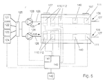
- Figure 5
- is a schematic view of an apparatus containing
a flow cell according to the invention, in a
second embodiment; and
- Figure 6
- is a schematic view of a third embodiment of
an apparatus according to the invention.
In the drawing corresponding elements have corresponding
reference numbers.
In figs. 1 - 3, a flow cell 1 is shown, specifically for
use in a method according to the present invention. The
flow cell 1 comprises a first part 2, further referred to
as bottom part 2 and a second part 3, further referred to
as top part 3. The flow cells are all shown schematically
and are not to scale. Proportions and dimensions can vary.
Between the bottom part 2 and top part 3, a channel or
similar vessel 4 is enclosed which connects a liquid inlet
5, on one side of the flow cell 1, with a liquid outlet 6
on the opposite side of the flow cell 1. The top part 3 is
connected to the bottom part 2 by a hinge 7 along a side of
the flow cell parallel to the length of the channel or
similar vessel 4. Between the bottom part 2 and the top
part 3 a seal 8 is positioned to prevent liquid passing
between the parts 2 and 3 during use, other then through
the channel or similar vessel 4.
On the bottom, 9, of the flow channel or similar vessel 4,
a first electrode 10, to be referred to as working
electrode (WE) is positioned near the liquid inlet 5. At
least one second electrode 11, a reference (RE) or counter
electrode (CE) is positioned on the bottom, 9 of the
channel or similar vessel, 4, downstream from the working
electrode 10. The, or each second or further electrode can
also be positioned upstream or in any other position,
distant from the first electrode, such that interference of
the electrodes is avoided. The electrodes are preferably of
a screen-printed type and can be either positioned on the
channel or similar vessel bottom 9 or, preferably, in a
recess in the channel or similar vessel bottom 9, such that
the upper surface of the electrodes 10, 11 are flush with
the surface of the channel or similar vessel bottom 9, in
order to minimise turbulence during use.
Over the working electrode 10, a solid phase 12 is
positioned, for example in the form of a sheet of nitro-cellulose
or any other suitable solid phase. The sheet of
solid phase 12 has a width somewhat greater then the width
of the channel or similar vessel 4 perpendicular to flow
direction thereof. The sheet 12 is provided with opposite
side parts 13 clamped between the bottom part 2 and top
part 3 when the flow cell 1 is in its closed position (fig.
2). The sheet 12 is preferably mainly provided with
reactive solid phase on the side directed to the working
electrode 10, while the working electrode 10 is covered by
the sheet 12. During use liquids can pass trough the
channel or similar vessel over the sheet 12, between the
sheet 12 and the working electrode 10 as well as between
the sheet 12 and the channel or similar vessel roof 14
opposite the channel or similar vessel bottom 9, thereby
reacting with the solid phase.
The top part 3 can be pivoted to an opened position, shown
in broken lines in fig. 2. In this opened position the
channel or similar vessel 4, especially the electrodes 10,
11 and the solid phase 12 are directly accessible. The
sheet 12 of solid phase can be taken out of the relevant
part 2, 3 and be exchanged for a new sheet 12 of solid
phase, after which the top part 3 can be brought in the
closed position against the bottom part 2 again, clamping
the solid phase in position. In the opened position
furthermore the channel or similar vessel 4 forming parts,
the electrodes 10, 11 and the seals can be handled, if
necessary. This flow cell 1 therefore has the advantage
that it can be re-used after exchange of the solid phase,
which can be easily achieved.
Fig. 4 shows a schematic view of an apparatus 20 containing
a flow cell 1 according to the invention. The apparatus 20
comprises a first source 21 of a liquid suspected of
comprising an analyte, for example milk, a second source 22
of a liquid comprising a substrate, a third source 23 of a
liquid comprising a molecule having a specific binding
affinity for the analyte and a fourth source 24 of a liquid
containing a molecule having a label. The apparatus
furthermore comprises a multi-valve 25, connected to the
inlet-side with the said sources 21 - 24. The outlet-side
of the multi-valve 25 is connected to a first conduit 26,
connected to the liquid inlet 5 of the flow cell 1. A
second conduit 27 is connected to the liquid outlet 6
thereof, for discharge of the liquids from the flow cell.
In the first conduit 26 a pump 28 is positioned for pumping
the liquids from the respective sources 21 - 24 to and
through the channel or similar vessel 4. The pump 28 is
preferably of a peristaltic type, capable of very precisely
pumping small amounts of liquids, for example as little as
0.1 ml per charge. This enables very accurate dosage of the
liquids.
In fig. 5 a second embodiment of an apparatus according to
the invention is shown schematically, wherein a flow cell
101 is provided with two parallel channels or similar
vessels 104, each channel or similar vessel 104 provided
with a series of measuring electrodes 110 and corresponding
solid phases 112. Each solid phase 112 is intended for
detecting a specific analyte. In this embodiment a mixing
apparatus 130 is connected to at least two sources, in the
embodiment shown as an example the first 121 and second
source 122. In the mixing apparatus 130 a combination can
be obtained of a specific dosage of the liquid from the
connected sources, for example for pre-labeling of the
analyte in the sample. The outlet-side of the mixing
apparatus 130 is connected to an inlet-side of the multi-valve
125, as are the other sources 123 and 124. The outlet
side of the multi-valve 125 is connected to the liquid
inlets 105 of the respective channels or similar vessels
104 of the flow cell 101. It will be apparent that the
channels or similar vessels 104 can also be provided in
different flow cells, whereas any number of measuring
electrodes can be positioned in any one of the channels or
similar vessels.
In the channels or similar vessels 104 of the flow cell
101, a counter electrode 140 is positioned between the
working electrode 110, at least downstream of the last
working electrode 110, and the reference electrode 111 for
enhancing the results of measurements, especially when high
currents and/or high fluctuations in currents require
detection.
The electrodes 10, 11 or 110, 111, 140 are connected to a
measuring device 41, 141 respectively. Only the measuring
device 41 will be described more extensively, the measuring
device 141 being comparable to this device 41. The
measuring device is provided with means for maintaining an
operating potential across the electrodes 10, 11.
Furthermore the device 41 is provided with means for
detecting current fluctuations, resulting from
electrochemical reactions on or near the working electrode
10. The resulting fluctuations are presented by a means of
a display 42 connected to the measuring device as, for
example, absolute levels of measured current (mA) at a
given reference time after initiation of the
electrochemical reaction or as changes in the measured
current in (δmA/sec).
Instead of one pump 28, 128 in the first conduit 26, 126 a
pump can be positioned in the second conduit 27 or a number
of pumps can be positioned in conduits between the
respective sources 21 - 24, 121 - 124 and the multi-valve
25, 125.
The measuring device can be integrated in a control device
143, further comprising means for operating the sources 21
- 24, 121 - 124, the or each pump 28, 128, the multi-valve
25, 125 and/or the voltage over the electrodes 10, 11, 110,
111, 140. This control device 143 is preferably
programmable and designed for (semi)automatic operation of
the apparatus.
The measuring and/or control device 42, 142, 43, 143 is
further provided with means for maintaining a potential
difference between at least two of the electrodes, which
difference can be positive or negative, relative to the or
each working electrode, depending upon the particular
reaction. Preferably, the means for obtaining said
potential difference is designed for maintaining this
difference at a relatively constant level, in order to
obtain smooth signal data, which is readily available and
interpretable and has a high signal/noise ratio.
Heating and/or cooling systems can be provided for
regulating the temperature of the liquids.
In an alternative embodiment, as shown in fig. 6, a number
of said sources 21-24, 121-124 are connected to the second
conduit 27, 127, by means of a pump 28, 28', 128, 128'
provided for directing liquids from said sources in either
direction through the channel or similar vessel, depending
upon the positions of the respective sources. In this
embodiment a liquid can be expelled from the channel or
similar vessel 4, 104 by feeding the next liquid to said
channel or similar vessel, wherein the liquid is forced
forward or backward through the channel or similar vessel
wherein the liquid can be forced back to its initial source
or can be expelled.
In the embodiments shown, the electrodes are positioned in
the channel or similar vessel, at a fixed distance apart
from each other. In a further preferred embodiment, not
shown, the electrodes to be used in a flow cell 1, 101, a
number of these electrodes, preferably all electrodes (WE,
CE and/or RE) are positioned on a card or the like,
preferably printed thereon by for example thick film
screen-printing methodology, the card being easily
replaceable. Contact pads or the like are provided within
the flow cell for connection of the electrodes to the
measuring device.
Part or all of the solid phase can be positioned directly
on the working electrode thus providing for easy
positioning and removal thereof and for protection of the
said electrode, if necessary, against corrosive or
otherwise reactive components within the liquids to be fed
through the channel or similar vessel.
The invention is in no way limited to the embodiments as
shown in the description and the drawings. Many
modifications and variants are possible within the scope of
the invention as defined in the enclosed claims. For
example a number of flow cells or a number of channels or
similar vessels can be connected to different sources of at
least the first kind, that is sample sources, each cell or
channel being connectable to the same second, third and/or
fourth or further sources, depending on the particular
operation undertaken. On the other hand one cell or channel
or similar vessel can be connectable to a number of said
sample sources, whereby means are provided for subsequently
performing a full measuring cycle on a sample of each first
source. These embodiments are for example useful when a
number of similar samples require testing for similar
analytes. Furthermore, the or each channel or similar
vessel can have a different cross-section and flow path.
The electrodes can have various forms and can be made of
different materials or combinations thereof, mainly
depending on the currents to be measured, the space
available and the measurement conditions such as the solid
phase to be used and the pH of the various liquids used.
Different numbers of sources can be connectable to the or
each flow cell. Furthermore the flow cell can be
constructed in a different form, for example of two or more
parts being fully separable from each other. The solid
phase and/or the electrodes can be mountable within the
channel or similar vessel in different ways, for example
integrated onto one carrier which could be maneuvered into
place to form a channel or similar vessel. A flow cell
having such a construction would not require disassembly
and re-assembly of the flow cell in order for replacement
of the sensor device. Furthermore the solid phase could be
positioned within the channel or similar vessel by other
mounting means, for example along one side on the channel
or similar vessel base, on the upstream side. A number of
suitably prepared flow cells can be positioned in line and
mounted in such a way that they can be adjusted to allow
subsequent positioning of the flow cells subsequently
between the first and second conduit to allow a series of
measurements to be performed.
These and many similar variants are to be considered as
falling within the scope of the invention.