EP0859308A1 - Library control device for logically dividing and controlling library device and method thereof - Google Patents
Library control device for logically dividing and controlling library device and method thereof Download PDFInfo
- Publication number
- EP0859308A1 EP0859308A1 EP97308684A EP97308684A EP0859308A1 EP 0859308 A1 EP0859308 A1 EP 0859308A1 EP 97308684 A EP97308684 A EP 97308684A EP 97308684 A EP97308684 A EP 97308684A EP 0859308 A1 EP0859308 A1 EP 0859308A1
- Authority
- EP
- European Patent Office
- Prior art keywords
- lun
- address
- library
- recording medium
- functional element
- Prior art date
- Legal status (The legal status is an assumption and is not a legal conclusion. Google has not performed a legal analysis and makes no representation as to the accuracy of the status listed.)
- Withdrawn
Links
Images


Classifications
-
- G—PHYSICS
- G06—COMPUTING; CALCULATING OR COUNTING
- G06F—ELECTRIC DIGITAL DATA PROCESSING
- G06F3/00—Input arrangements for transferring data to be processed into a form capable of being handled by the computer; Output arrangements for transferring data from processing unit to output unit, e.g. interface arrangements
- G06F3/06—Digital input from, or digital output to, record carriers, e.g. RAID, emulated record carriers or networked record carriers
- G06F3/0601—Interfaces specially adapted for storage systems
- G06F3/0602—Interfaces specially adapted for storage systems specifically adapted to achieve a particular effect
- G06F3/0604—Improving or facilitating administration, e.g. storage management
- G06F3/0607—Improving or facilitating administration, e.g. storage management by facilitating the process of upgrading existing storage systems, e.g. for improving compatibility between host and storage device
-
- G—PHYSICS
- G06—COMPUTING; CALCULATING OR COUNTING
- G06F—ELECTRIC DIGITAL DATA PROCESSING
- G06F3/00—Input arrangements for transferring data to be processed into a form capable of being handled by the computer; Output arrangements for transferring data from processing unit to output unit, e.g. interface arrangements
- G06F3/06—Digital input from, or digital output to, record carriers, e.g. RAID, emulated record carriers or networked record carriers
- G06F3/0601—Interfaces specially adapted for storage systems
- G06F3/0628—Interfaces specially adapted for storage systems making use of a particular technique
- G06F3/0655—Vertical data movement, i.e. input-output transfer; data movement between one or more hosts and one or more storage devices
- G06F3/0658—Controller construction arrangements
-
- G—PHYSICS
- G06—COMPUTING; CALCULATING OR COUNTING
- G06F—ELECTRIC DIGITAL DATA PROCESSING
- G06F3/00—Input arrangements for transferring data to be processed into a form capable of being handled by the computer; Output arrangements for transferring data from processing unit to output unit, e.g. interface arrangements
- G06F3/06—Digital input from, or digital output to, record carriers, e.g. RAID, emulated record carriers or networked record carriers
- G06F3/0601—Interfaces specially adapted for storage systems
- G06F3/0668—Interfaces specially adapted for storage systems adopting a particular infrastructure
- G06F3/0671—In-line storage system
- G06F3/0683—Plurality of storage devices
- G06F3/0686—Libraries, e.g. tape libraries, jukebox
-
- G—PHYSICS
- G11—INFORMATION STORAGE
- G11B—INFORMATION STORAGE BASED ON RELATIVE MOVEMENT BETWEEN RECORD CARRIER AND TRANSDUCER
- G11B27/00—Editing; Indexing; Addressing; Timing or synchronising; Monitoring; Measuring tape travel
- G11B27/002—Programmed access in sequence to a plurality of record carriers or indexed parts, e.g. tracks, thereof, e.g. for editing
-
- G—PHYSICS
- G11—INFORMATION STORAGE
- G11B—INFORMATION STORAGE BASED ON RELATIVE MOVEMENT BETWEEN RECORD CARRIER AND TRANSDUCER
- G11B2220/00—Record carriers by type
- G11B2220/40—Combinations of multiple record carriers
- G11B2220/41—Flat as opposed to hierarchical combination, e.g. library of tapes or discs, CD changer, or groups of record carriers that together store one title
Definitions
- the present invention relates to a technology for controlling a large-scale library device by using a small-scale host computer, more specifically, to a library control device for logically dividing a library device into a plurality of logical units and controlling it, and a method thereof.
- a library device is put to commercial use in various fields for automatically performing import/export, storage, read/write of a recording medium and the like.
- a recording medium an optical disk, compact disk read only memory (CD-ROM), magnetic tape or so on, is utilized.
- FIG.1A is a schematic drawing of the conventional large-scale magnetic tape library.
- a large scale magnetic tape library set (MTL) consists of frames for each function.
- the magnetic tape library in FIG.1A comprises four frames, RAU, DAU 0, TAU 0, and LAU storing MT cartridges, and is controlled by the library controller 1 in the frame ACU.
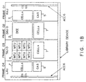
- FIG.1B is a schematic diagram of in the internal configuration of the subsystem of the magnetic tape library.
- RAU is a frame located on the right side of the subsystem and is a frame comprising a cartridge access station (CAS) 5, accessor (ACC) 6, and a plurality of cells (CELLs) 7.
- CAS 5 is a special cell for importing/exporting a recording medium to the library device and is operable in the online (READY) state.
- ACC 6 is a robot for transporting the recording medium within the library device, and the cells 7 are slots for storing recording media.
- DAU 0 is a frame comprising a direct entry exit unit (DEE) 2 and a plurality of cells 7.
- DEE 2 is a unit for importing/exporting a recording medium in units of frames in the offline (NOT READY) state.
- DEE 2 for example, by providing a rotating cell drum and a large access door 3, can perform the import/export operations of a large quantity of the recording media in a short time.
- TAU 0 is a frame comprising a plurality of magnetic tape units (MTUs) 4 and a plurality of cells 7.
- MTU 4 is a cell for driving a recording medium for reading/writing.
- LAU similar to RAU, is located on the left side and comprises CAS 5, ACC 6, and a plurality of cells 7.
- ACC 6 can move arbitrarily among the frames, and transports the recording medium to and from each of CAS 5, CELLs 7, DEE 2 and MTU 4, according to an instruction from the library controller 1.
- the addresses of the CELLs 7, DEE 2, CAS 5, and MTU 4 are controlled by a combination of the frame number with the addresses within that frame.
- RAU, DAU 0, TAU 0, and LAU for example, the frame numbers 01, 02, 03, and 04 are allocated to each frame, and addresses of three bytes are utilized for each frame.
- An embodiment of the present invention may provide a library control device for controlling a large-scale library device by means of such a general-use interface as SCSI and a method thereof.
- the library control device comprises a memory unit and a control unit.
- the memory unit stores logical structure information representing the configuration of the library device divided into a plurality of logical units, each suitable for independent control.
- the control unit controls the operations of the library device using the logical structure information.
- Each frame of the library device is, for example, regarded as one logical unit in SCSI, and the library device is divided into as many logical units as frames. Accordingly, even in such a large-scale library device with more addresses than are available using 2 bytes, each division of it is independently controllable as a medium changer device in SCSI.
- the host system issues the medium transfer commands to the medium changer device and directs the control unit to control the library device, and it is necessary to assign element addresses of an accessor, a transfer source, and a transfer destination, when the command is issued.
- a virtual transport element is provided to logical units containing no accessor(ACC), and the element addresses are assigned. These element addresses correspond to an address of the real ACC.
- the medium transfer command can be issued even to logical units containing no ACCs.
- virtual import/export elements are provided with the function to import/export a recording medium between two logical units, so as to enable commands for recording medium transfer, and element addresses are assigned to these virtual elements.
- the control unit processes the commands to different logical units in association with a check of the logical structure information, on receipt of a command for each logical unit from the host system. Based on the result of this process, the control signal is issued to control the library device.
- the logically divided library device can be controlled in a unified manner by providing virtual functional elements which do not exist in each of the library devices, in cooperation with the SCSI interface.
- the library device comprises a storage unit and a control unit.
- the storage unit stores a plurality of recording media
- the control unit controls the library device by dividing it into a plurality of logical units, each suitable for independent control.
- the control device comprises a memory unit and a control unit.
- the memory unit stores logical structure information representing the configuration of a control object divided into a plurality of logical units, each suitable for independent control.
- the control unit controls the control object using the logical structure information.
- the host system comprises a memory unit and a command issuing unit.
- the memory unit stores logical structure information representing the configuration of the library device divided into a plurality of logical units each suitable for independent control.
- the command issuing unit issues commands to each of the plurality of logical units.
- FIG.2A shows a principle of the library control device embodying the present invention.
- the library control device comprises a memory unit 11 and a control unit 12.
- the memory unit stores the logical structure information representing the configuration of the library device, divided into a plurality of logical units each suitable for independent control.
- the control unit controls the operations of the library device using the logical structure information.
- Each frame of the library device is, for example, considered to be one logical unit in SCSI and the library device is divided into as many logical units as there are frames. Accordingly, even in such a large-scale library device with more addresses than are available using 2 bytes, each division of it is independently controllable as a medium changer device in SCSI.
- the 2 bytes of the element addresses such as cell addresses are written for each of the logical units.
- LUN represents a logical unit number and the letter (h) in the column for the element address shows that the addresses are written as hexadecimal numbers.
- the host system issues a medium transfer command to the medium changer device and directs the control unit 12 to control the library device, and it is necessary to assign element addresses of the accessor, the transfer source, and the transfer destination, when the command is issued.
- a virtual accessor is provided in these logical units and an element address is assigned to the virtual accessor.
- This element address is made to correspond to an address of a real accessor.
- the medium transfer command can be issued to both LUN 1 and LUN 2.
- virtual import/export elements with the function of transferring a recording medium between two adjoining or remote logical units are provided so as to facilitate the recording medium transfer between different logical units, and element addresses are assigned to these virtual elements.
- the host system can command a transfer between different logical units by issuing two linked commands to a pair of import/export elements corresponding to each other.
- a command to transfer a medium from LUN 0 to LUN 1 for example, a first command is initially issued to LUN 0 to transfer the medium to the address 0100, followed by a second command to LUN 1 to transfer the medium from the address FF01.
- the control unit 12 processes the commands to different logical units in association with a check of the logical structure information, on receipt of the command from the host system, for each logical unit. Based on the result of this process, the control signal is issued to control the library device.
- the destination address 0100 of the first command is recognized to correspond to the source address FF01 of the second command, by referring to the logical structure information.
- the recording medium is transferred between these virtual elements, and the library device is controlled to transfer the recording medium directly from the source element address of the first command, to the destination element address of the second command.
- the logically divided library device can be controlled in a unified manner by providing virtual functional elements which do not exist in each of the library devices, in co-operation with the SCSI interface.
- the NOT READY state can be set in each of the logical units by logically dividing the library device.
- the added frames can be defined as new ones, and no revision is required to the addresses of the existing elements. Accordingly, predetermined addresses can be stored even though the model is structurally modified or upgraded, without rewriting addresses represented on manufacture.
- the memory unit 11 in FIG.2A corresponds to the memory 33 in FIG.4 described later
- the control unit 12 corresponds to the interface 31, 34, and processing unit 32
- the logical structure information corresponds to the address information shown in FIGS.7, 8, 9,10 and 11.
- the library controller 1 (FIG.1A) of the library device interprets a command set for the medium changer device in SCSI to control the library device, by association with the library management software of the upper host computer. Therefore, the library controller 1 serves as the SCSI controller.
- the library device is logically divided into a plurality of logical units, not treated as one logical unit as in SCSI-2.
- a logical unit number (LUN) in SCSI is assigned to each of the frames comprising the library device.
- LUN logical unit number
- 2 byte addresses can be defined for each frame, and it is possible to deal with the large-scale library device with more cell addresses than are available using 2 bytes.
- the host computer issues to the library controller 1 one or more commands directing linking operations among a plurality of logical units or frames under control, resulting in controlling a library device set.
- virtual cells are provided, as described below, in each frame:
- to provide virtual cells means to set cell addresses representing dummy functions.
- the library controller 1 recognizes whether or not the command issued from the host computer to each LUN is a transfer command necessary to be linked with other LUNs.
- the library controller 1 stores the command without executing any operation, until a series of commands have been issued to terminate the linking operation.
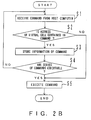
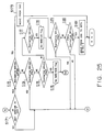
- FIG.2B is a flowchart of the control process in a plurality of logical units performed by the library controller 1.
- the library controller 1 receives a command for one of the logical units from the host computer (step S1), followed by the determination of whether or not any virtual cell address is included in the received command (step S2), and the received command is temporarily stored if such addresses are included (step S3).
- step S4 a decision is made as to whether or not a series of stored commands are executable. These commands are judged executable if the addresses of the virtual cells included in these commands constitute a corresponding pair, and if the physical transfer source and destination of the recording medium can be specified. On the other hand, these commands are judged unexecutable if virtual cell addresses which do not correspond to any of the addresses of existing real units remain in the commands.
- step S1 If a series of commands are judged unexecutable, the following command is fed from the host computer (step S1), and the iterative process in and after step S2 is performed. If a series of commands are executable, these commands are interpreted together to operate the library device (step S5), and the process is terminated. In step S2, the command is instantly executed to terminate the process, when it is determined that no addresses of virtual cells are included in the command.
- one frame can be regarded as one logical unit controllable in SCSI, by providing appropriate virtual cells in each frame. Accordingly, the host computer can issue a medium transfer command to each frame. Further, it is made possible to set the address of the virtual cell in correspondence with a real function and to control the logically divided library device by interpreting and executing a series of mutually related commands.
- the library device can inform the host computer of the NOT READY state in each LUN when it is required to set a frame into the NOT READY state, since the host computer individually controls each of the logical units.
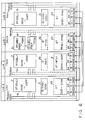
- FIG.3 shows the structure of the control system in the large-scale library device as one of the preferred embodiments.
- LUN 0, LUN 1, LUN 2, and LUN 3 are assigned to the four frames RAU, DAU 0, TAU 0, and LAU, in that order, and each frame is recognized as an independent logical unit. In some cases as described below, each frame is identified in accordance with the LUN form.
- the frame RAU for example, is only represented as LUN 0.
- the accessor 6 in LUN 0 and LUN 3 is defined as the transport element (TR) in SCSI, and the hexadecimal address 0000 is assigned.
- TR transport element
- hexadecimal address 0000 is assigned.
- an element in SCSI means a cell in the broader sense, including the real cell 7.
- CAS 5 is defined as the import/export element (IE) to which the address 0001 is assigned.
- the cells 7 are defined as the storage elements (ST) to which the addresses 0002 to 00FF are assigned.
- ST storage elements
- DEE 2 and the cells 7 are defined as the storage elements to which the addresses 0000 to F000 and F0001 to FF00 are assigned, respectively.
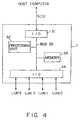
- FIG.4 is a structural chart of the library controller 1 shown in FIG.3.
- the library controller 1 comprises a SCSI input/output interface (I/O) 31, processing unit 32, memory 33, and input/output interface (I/O) 34 for each frame. These elements are connected by means of a bus 35.
- I/O SCSI input/output interface
- processing unit 32 processing unit 32
- memory 33 memory 33
- I/O input/output interface
- the interface 31 receives the commands from the host computer 21 and transmits the response back to the host computer 21.
- the memory 33 includes a read only memory (ROM) for storing data and programs and a random access memory (RAM) for processing.
- the processing unit 32 executes the programs stored in the memory 33 using the data stored in the memory 33. Based on the result, the command is interpreted to instruct an operation in each frame.
- the interface 34 sends a control signal on the basis of the control from the processing unit 32. In this manner, the library controller 1 executes the commands from the host computer 21 to operate the library device 22.
- FIG.5 shows a data configuration of the medium transfer command (MOVE command) in SCSI, transferred to the library controller 1.
- MOVE command MOVE command
- CDB 0 represents the operation code corresponding to the medium transfer
- CDB 1 shows the LUN of the logical unit of the command issue object.
- CDB 2 and CDB 3 represent the address of the transport element in the logical unit
- CDB 4 and CDB 5 the address of the source element
- CDB 6 and CDB 7 the address of the destination element. These addresses are represented in the form of 2 bytes.
- the MOVE command in SCSI can direct the medium transfer only between the elements in a specified logical unit.
- the MOVE command cannot direct the medium transfer between different logical units.
- no accessor is included in LUN 1 and LUN 2, and no definition is given to the transport element. Therefore, the MOVE command cannot be issued to these logical units without some modification.
- the host computer 21 provides an appropriate virtual transport element, virtual import/export element, and virtual data transfer element, and issues the MOVE command including the addresses of these virtual elements.
- the virtual transport element 41 and the virtual import/export element 42 are provided to LUN 1 and LUN 2 having no ACC 6 and CAS 5.
- the transport element 41 and the import/export element 42 respectively correspond to the real ACC 6 and CAS 5.
- the addresses 1004 and 1005 are assigned respectively to the transport element 41 and the import/export element 42 in LUN 2 and the addresses FF04 and FF05 are assigned respectively to the transport element 41 and the import/export element 42 in LUN 1.
- the host computer 21 can utilize the transport element address (CDB 2 and CDB 3) of the MOVE command to cover LUN 1 and LUN 2, and can issue a MOVE command to these frames.
- CDB 2 and CDB 3 transport element address
- the host computer can utilize addresses corresponding to CAS 5 in other frames, as the source element address (CDB 4 and CDB 5) or the destination element address (CDB 6 and CDB 7) of the MOVE command to LUN 1 and LUN 2.
- the recording medium transfer between CAS 5 and LUN 1 or LUN 2 can be directly commanded to LUN 1 or LUN 2.
- 8 sets of virtual data transfer elements corresponding to 8 sets of MTU 4 in LUN 2 are provided to LUN 0, LUN 1, and LUN 3 which have no MTU 4.
- the addresses 0103 to 010A are assigned to the data transfer elements 43 in LUN 0 and LUN 3, and the addresses FF06 to FF0D to the data transfer elements 43 in LUN 1.
- the host computer 21 can utilize addresses corresponding to MTU 4 in LUN 2, as the source element address or the designation element address of the MOVE command to LUN 0, LUN 1, and LUN 3.
- addresses corresponding to MTU 4 in LUN 2 as the source element address or the designation element address of the MOVE command to LUN 0, LUN 1, and LUN 3.
- the recording medium transfer between MTU 4 and LUN 0, LUN 1, or LUN 3 can be directly commanded to LUN 0, LUN 1, or LUN 3.
- a virtual import/export element 44 is provided for all frames.
- the addresses 0100, 0101, and 0102 are assigned to the 3 sets of import/export elements 44 in LUN 0, and the addresses FF01, FF02 and FF03 to the 3 sets of import/export elements in LUN 1.
- addresses 1001, 1002 and 1003 are assigned to the 3 sets of import/export elements 44 in LUN 2, and the addresses 0100, 0101 and 0102 to the 3 sets of import/export elements 44 in LUN 3.
- the element 44 at the address 0100 in LUN 0 corresponds to the element 44 at the address FF01 in LUN 1.
- the virtual recording medium transfer can be performed between these elements.
- the host computer 21 can direct the recording medium transfer between LUN 0 and LUN 1, by applying the addresses of these import/export elements 44 to the source element or the destination element of the MOVE command.
- the import/export element 44 at the address 0101 in LUN 0 corresponds to the import/export element 44 at the address 1003 in LUN 2, and the import/export element 44 at the address 0102 in LUN 0 to the import/export element 44 at the address 0102 in LUN 3.
- the import/export element 44 at the address FF02 in LUN 1 corresponds to the import/export element 44 at the address 1001 in LUN 2
- the import/export element 44 at the address FF03 in LUN 1 corresponds to the import/export element 44 at the address 0101 in LUN 3
- the import/export element 44 at the address 1002 in LUN 2 corresponds to the import/export element 44 at the address 0100 in LUN 3.
- the host computer 21 can utilize addresses corresponding to other frames as the source element or the destination element of the MOVE command, and the recording medium transfer can be directed between arbitrary frames.
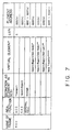
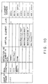
- FIGS.7 to 10 are tables showing the addresses of each of the real and the virtual elements.
- FIGS. 7, 8, 9, 10 show the element addresses of LUN 0, LUN 1, LUN 2 and LUN 3, respectively.
- the real function represents the real element shown by the solid lines in FIG.6, and the virtual element represents the virtual element shown by the dotted lines in FIG.6.
- the notation import/export (RAU - DAU 0) in FIG.7 represents that this is the element for virtually importing/ exporting the recording medium between RAU and DAU.
- the letter (h) in the element address shows that the addresses are given as hexadecimal numbers.
- the virtual element with the symbol '*' corresponds to the element 44 for virtually importing/exporting the recording medium between two frames in adjoining positions
- the virtual element with the symbol '**' is the element 44 for virtually importing/exporting the recording medium between two frames in remote positions.
- the virtual element with the symbol '***' corresponds to the transport element 41
- the virtual element with the symbol '****' corresponds to the import/export element 42
- the virtual element with the symbol '*****' corresponds to the data transfer element 43.
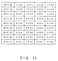
- the data transfer elements 43 in LUN 0, LUN 1, and LUN 3 are in one-to-one correspondence with the addresses of MTU 4 in LUN 2, and the relation is shown in the address reference table in FIG.11.
- the host computer 21 and the library controller 1 store the LUN and a part or all of the address information shown in FIGS.7 to 11 as the management information, and control the library device 22 with reference to the information.
- the present embodiment divides the whole library device 22 into frames as logical units in SCSI.
- the divided large-scale library device is controlled for the recording medium transfer between logical units. Detailed explanation will be given in the following about the control method.
- the application program executed in the host computer 21 specifies the volume name of the recording medium, and informs the library management software in the host computer 21 of the operating procedure of the library device 22.
- the volume name for example, is given in a combination of six letters/ figures.
- the operating procedure includes the action of mounting a recording medium in the MTU 4, the exporting action from DEE 2 or CAS 5 out of the library device 22, and the like.
- the library management software calculate from the informed volume name an element address of the library device 22 in which the objective recording medium is stored. In addition, the library management software determines the destination element address of the recording medium, in accordance with the operation procedure informed by the application program. Depending on the operation procedure, however, there are some cases when no recording medium transfer is required.
- the library management software issues the appropriate commands for dealing with the recording medium through the interface between the host computer 21 and the library controller 1.
- the library controller 1 operates the recording medium in accordance with the commands from the host computer 21.
- the first operating example is that the recording medium of the volume 'XXXXX' in the address 1000 of DEE 2 in the frame DAU 0 is mounted in MTU 4 at the address 0001 in the frame TAU 0.
- the above operation is explained according to the general operation described above, as follows:-
- the application program informs the library management software of a command for mounting the volume 'XXXXX' in MTU 4. At this point, no destination element address is specified.
- the library management software retrieves the element address information that the volume 'XXXXX' is stored, recognizes that it is stored at the address 1000 of LUN 1, checks for free space in MTU 4, and decides, for example, that the volume can be mounted in the address 0001 in TAU 0.
- One of the methods for retrieving the element address from the volume name is that it is retrieved from a medium information database managed by the library management software.
- Another method is that correspondence information between the volume information of the recording medium and the element address is included in the library controller 1, and that the command for collecting such information is issued to the library controller 1 for retrieval by the library management software. In general, the former method is often used.
- the library management software initially issues the MOVE command for LUN 1 to the library controller 1.
- the recording medium in the address 1000 in DAU 0 is transferred to the virtual import/export element 44 at the address FF02 for a transfer from DAU 0 to TAU 0, by utilizing the virtual transport element 41 at the address FF04.
- the library management software issues the MOVE command for LUN 2.
- the recording medium in the virtual import/export element 44 in the address 1001 in TAU 0 is transferred to MTU 4 in the address 0001, by utilizing the transport element 41 in the address 1004.
- the library controller 1 On receiving the initial MOVE command, the library controller 1 supposes that the recording medium in the address 1000 in DAU 0 is transferred to the import/export element 44 in the address FF02. On receiving the second MOVE command, the library device 22 is really operated to transfer the recording medium. At this point, the accessor 6 in RAU or LAU is operated to mount the recording medium from the address 1000 in DAU 0 in MTU 4 in the address 0001 in TAU 0.
- the recording medium transfer is realized between the adjoining logical units, by utilizing the virtual transport element 41 and the virtual import/export element 44.
- the library management software issues a plurality of related commands necessary for operating the recording medium to the library controller 1, and enables the medium operation by the application program in the host computer 21.
- the library controller 1 controls the divided library device 22 by processing a plurality of received commands which are linked.
- the recording medium is transferred in turn to the adjoining logical unit by liking a plurality of commands, finalizing the transfer to a remote destination.
- the direct transfer can be commanded by utilizing the import/export element directly connecting the remote logical units.
- the latter is more effective than the former because the number of commands is reduced in the latter.
- the second operating example is that the volume 'YYYYYY' in the address 0002 of the frame RAU is mounted in MTU4 in the address 0001 in the frame TAU 0.
- the operation in this example is explained in accordance with the general operation described above.
- the application program directs the library management software to mount the volume 'YYYYYY' in MTU 4. In this case, no destination element address is specified.
- the library management software retrieves the element address information that the volume 'YYYYYY' is stored, recognizes that it is stored at the address 0002 in LUN 0, checks for free space in MTU 4, and decides to mount it in MTU 4 in the address 0001 in TAU 0. The same method for retrieval is taken in this case as in the first operating example.
- the library management software issues the MOVE command for LUN 0 to the library controller 1.
- the recording medium in the address 0002 in RAU is directed to move to the virtual data transfer element 43 in the address 0104, by utilizing the transport element 6 in the address 0000.
- the library controller 1 On receiving the MOVE command described above, the library controller 1 confirms, with reference to the address table in FIG.11, that the data transfer element 43 in the address 0104 corresponds to MTU 4 in the address 0001 in LUN 2 (TAU 0), and mounts the recording medium from the address 0002 in RAU in MTU 4 in the address 0001 in TAU 0.
- the recording medium transfer from the logical unit having no MTU 4, to the logical unit having MTU 4 can be executed by a single command by utilizing virtual data transfer element 43.
- a free data transfer element 43 can be easily searched for by setting a flag indicating 'IN USE' state at the data transfer element 43 corresponding to that MTU 4.
- the recording medium transfer between the logical unit and a logical unit having CAS 5 is realized.
- the recording medium transfer from the CELL 7 in RAU to MTU 4 in TAU 0 in the second operating example is replaced by the recording medium transfer from DEE 2 in DAU 0 to CAS 5 in RAU or LAU, the operation described above can be explained with ease.
- such case is projected as moving the volume 'ZZZZZZ' from the address 0000 in the frame DAU 0 to CAS 5.
- the operation in this case will be explained in accordance with the general operation described above.
- the application program informs the library management software to move the volume 'ZZZZZZ' to CAS 5. At this time, the destination element address is not specified.
- the library management software retrieves the element address information that the volume 'ZZZZZZ' is stored, recognizes that it is stored at the address 0000 in DAU 0, checks for free space in CAS 5, and determines to move the volume to CAS 5 in the address 0001 in RAU. The same procedure is executed in the retrieval as in the first operating example described above.
- the library management software issues to the library controller 1 the MOVE command for LUN 1. This command directs the library controller 1 to move the recording medium from the address 0000 in DAU 0 to the virtual import/export element 42 in the address FF05, by utilizing the virtual transport element 41 in the address FF04.
- the library controller 1 On receiving the above MOVE command, the library controller 1 confirms that the import/export element 42 in the address FF05 corresponds to CAS 5 in the address 0001 in RAU. Further, the library controller 1 actuates ACC 6 in RAU to move the recording medium from the address 0000 in DAU 0 to CAS 5 in RAU.
- the READY/NOT READY state can be controlled for each of the logical units. Therefore, it is clearly represented that a specific logical unit can be used on the SCSI interface. Accordingly, it becomes possible to keep the library device 22 active during maintenance and to make it partially offline for maintenance.
- the library controller 1 when a new frame is added to the library device 22, the library controller 1 has only to add the LUN of the new frame to the control information, while the LUNs of the existing frames are unmodified. No revision of unit addresses is required.
- the location of a frame can be determined arbitrarily in the library device 22. It is possible to show the element addresses designated in the frame on manufacture. No changes are required in the addresses even in cases of model change or frame addition.
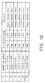
- FIG.12 shows the table for storing control data for the virtual import/export element 44. This table is stored in the memory 33 of the library controller 1.
- a pair of import/export elements 44 are shown as a mutually corresponding set.
- the first control data 'RAU - DAU 0' relates to the recording medium transfer between RAU and DAU 0, and is used for controlling a set of paired import/export elements 44 in the address 0100 in RAU (LUN 0) and in the address FF01 in DAU 0(LUN 1).
- the library controller 1 When the host computer 21 issues the MOVE command including an address of one of these import/export elements 44 as the destination, the library controller 1 sets the flag of the bit 19 in the control data 'RAU - DAU 0', and writes the LUN (3 bits) of the command and the source element address (16 bits) into the bits 18 - 0. By the above operation, the library controller 1 recognizes the completion of the command to transfer the recording medium between RAU and DAU 0.
- the library controller 1 On receiving the MOVE command including another corresponding address as the source, the library controller 1 resets the flag of the control data.
- the library controller 1 commands the real operation to the library device 22.
- the library controller 1 sets the flag by writing, for example, '1' to the flag, and resets the flag by writing '0'.
- the second control data 'RAU - TAU 0' controls a pair of the import/export elements 44 in the address 0101 in RAU and in the address 1003 in TAU 0(LUN 2).
- the third control data 'RAU - LAU' controls a pair of the import/export elements 44 in the address 0102 in RAU and in the address 0102 in LAU (LUN 3).
- the fourth control data 'DAU 0 - TAU 0' controls a pair of the import/export elements 44 in the address FF02 in DAU 0 and in the address 1001 in TAU 0, and the fifth control data 'DAU 0 - LAU' controls a pair of the import/export elements 44 in the address FF03 in DAU 0 and in the address 0101 in LAU.
- the sixth control data 'TAU 0 - LAU' controls a pair of the import/export elements 44 in the address 1002 in TAU 0 and in the address 0100 in LAU.
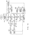
- FIG. 13 shows the overall flowchart of the library controller 1.
- the library controller 1 determines, first of all, whether or not the LUN written in the command is 0 (step S12). If LUN is 0, the library controller confirms if LUN 0 is in the READY state (step S13).
- step S15 a process for LUN 0 is performed (step S15), and the command is terminated (step S27). If LUN 0 is not ready, the library controller 1 returns the NOT READY response to the host computer 21 (step S14) and the command is terminated (step S27).
- LUN of the command If LUN of the command is not 0, it confirms if LUN is 1 (step S16). If LUN is 1, it confirms if LUN 1 is READY (step S17). If LUN 1 is READY, a process for LUN 1 is performed (step S18), and the command is terminated(step S27). If LUN is not READY, the NOT READY response is returned to the host computer 21 (step S14) and the command is terminated (step S27).
- LUN If LUN is not 1, it confirms if LUN is 2 (step S19). If LUN is 2, it confirms if it is READY (step S20). If LUN 2 is READY, a process for LUN 2 is performed (step S21), and the command is terminated (step S27). If LUN 2 is NOT READY, the NOT READY response is returned (step S14) and the command is terminated (step S27).
- LUN of the command determines if LUN is 3 (step S22). If LUN is 3, it confirms if LUN 3 is READY (step S23). If LUN 3 is READY, a process for LUN 3 is performed (step S24), and the command is terminated (step S27). If LUN 3 is NOT READY, the NOT READY response is returned (step S14) and the command is terminated (step S27).
- step S25 If LUN of the command is not 3, no corresponding logical unit exists, and an error procedure is executed (step S25).
- the library controller 1 informs, for example, the host computer 21 of an error.
- the command is terminated (step S27).
- the library controller 1 receives the following command from the host computer 21 and executes the same procedure.
- FIGS.14 to 16 show flowcharts of the LUN 0 process in step S15
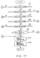
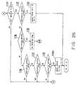
- FIGS.17 to 26 are flowcharts of the LUN 1 process in step S18
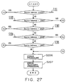
- FIGS. 27 to 33 show flowcharts of the LUN 2 process in step S21
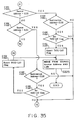
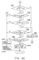
- FIGS.34 to 36 are flowcharts of the LUN 3 process in step S24.
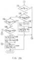
- the library controller 1 determines if the source element address of the command is lower than 0100 (FIG.14, step S31). If the source element address is lower than 0100, it determines if the destination element address is lower than 0100 (step S32). If the destination element address is lower than 0100, the command is restricted to RAU. The recording medium is transferred in RAU(step S33) and the process is terminated.
- step S32 if the destination element address is not lower than 0100, it determines if it is 0100 (step S34). If the destination element address is 0100, this command represents the recording medium transfer from RAU to DAU 0. LUN and the source element address of the command are stored in the control data 'RAU - DAU 0' (step S35), the flag is set (step S36) and the process is terminated.
- step S34 unless the destination element address is 0100, it is compared with the address 0101 (step S37). If the destination element address is 0101, this command represents the recording medium transfer from RAU to TAU 0. LUN and the source element address of the command are stored in the control data 'RAU - TAU 0' (step S38), the flag is set(step S39) and the process is terminated.
- step S37 unless the destination element address is 0101, it is compared with the address 0102 (step S40). If the destination element address is 0102, this command represents the recording medium transfer from RAU to LAU. LUN and the source element address of the command are stored in the control data 'RAU - LAU' (step S41), the flag is set (step S42) and the process is terminated.
- step S40 unless the destination element address is 0102, it is determined if it is not lower than 0103 and not higher than 010A (step S43). If the destination element address is within this range, the destination corresponds to MTU 4 in TAU 0. With reference to the address table in FIG.11, the recording medium is transferred from RAU to MTU 4 in TAU 0 (step S44) and the process is terminated.
- step S43 if the destination element address is lower than 0103 or higher than 010A, no corresponding address exists in RAU.
- the same error procedure is executed as in step S25 (FIG.16, step S67), the error recovery procedure is executed (step S68) and the process is terminated.
- step S31 if the source element address is not lower than 0100, it is determined if it is 0100 (FIG.15, step S51). If the source element address is 0100, the destination element address is compared with the address 0100 (step S52). If the destination element address is lower than 0100, it is confirmed if the flag of the control data 'RAU - DAU 0' is set (step S53).
- this command represents the recording medium transfer from DAU 0 to RAU.
- the flag of the control data 'RAU - DAU 0' is reset (step S54), the recording medium is transferred from the source element address in LUN stored in the control data to the destination element address in RAU (step S55) and the process is terminated.
- step S52 If the destination element address is not lower than 0100 in the step S52 and if the flag is not set in step S53, the command proceeds with the procedure in and after step S67 in FIG.16.
- step S51 unless the source element address is 0100, it is compared with the address 0101(step S56). If the source element address is 0101, the destination element address is compared with the address 0100 (step S57). If the destination element address is lower than 0100, it is confirmed if the flag of the control data 'RAU - TAU 0' is set (step S58).
- this command represents the recording medium transfer from TAU 0 to RAU.
- the flag of the control data 'RAU - TAU 0' is reset (step S59), the recording medium is transferred from the source element address in LUN stored in the control data to the destination element address in RAU (step S55) and the process is terminated.
- step S57 If the destination element address is not lower than 0100 in step S57 and if the flag is not set in step S58, the command proceeds with the procedure in and after step S67 in FIG.16.
- step S56 unless the source element address is 0101, it is compared with the address 0102(FIG.16, step S61). If the source element address is 0102, the destination element address is compared with the address 0100 (step S62). If the destination element address is lower than 0100, it is confirmed if the flag of the control data 'RAU - LAU' is set (step S63).
- this command represents the recording medium transfer from LAU to RAU.
- the flag of the control data 'RAU - LAU' is reset (step S69), the recording medium is transferred from the source element address in LUN stored in the control data to the destination element address in RAU (step S55) and the process is terminated.
- step S62 If the destination element address is not lower than 0100 in step S62 and if the flag is not set in step S63, the command proceeds with the procedure in and after step S67 in FIG.16.
- step S61 unless the source element address is 0102, it is determined if it is not lower than 0103 and not higher than 010A (step S64). If the source element address is within this range, the source corresponds to MTU 4 in TAU 0.
- step S65 the destination element address is compared with the address 0100 (step S65). If the destination element address is lower than 0100, the recording medium is transferred from MTU 4 in TAU 0 to RAU with reference to the address table in FIG.11 (step S66), and the process is terminated. In step S65, if the destination element is not lower than 0100, the command proceeds with the procedure in and after step S67.
- step S64 if the source element address is lower than 0103 or higher than 010A, no corresponding address exists in RAU. The command proceeds with the procedure in and after step S67.
- the library controller 1 determines if the source element address of the command is not higher than FF00 (FIG.17, step S71). If the source element address is not higher than FF00, the command proceeds with the procedure in and after step S81 in FIG.18. If the source element address is higher than FF00, it is compared with the address FF01 (step S72).
- the command proceeds with the procedure in and after step S101 in FIG.19. Unless it is FF01, it is compared with the address FF02 (step S73). If the source element address is FF02, the command proceeds with the procedure in and after step S131 in FIG.21. Unless it is FF02, it is compared with FF03 (step S74).
- the command proceeds with the procedure in and after step S151 in FIG.23. Unless it is FF03, it is compared with the address FF05 (step S75). If the source element address is FF05, the command proceeds with the procedure in and after step S171 in FIG.25. Unless it is FF05, it is determined if it is not lower than FF06 and not higher than FF0D (step S76).
- step S77 If the source element address is within the range, the command proceeds with the procedure in and after step S181 in FIG.26. If it is lower than FF06 or higher than FF0D, no corresponding address exists in DAU 0. The same error procedure is executed as in LUN 0 (step S77), the error recovery procedure is executed (step S78) and the process is terminated.
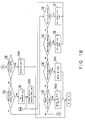
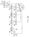
- step S71 if the source element address is not higher than FF00, it is determined if the destination address is not higher than FF00 (FIG.18, step S81). If the destination element address is not higher than FF00, the recording medium is transferred in DAU 0 due to the command being restricted to DAU 0 (step S82) and the process is terminated.
- step S81 if the destination element address is higher than FF00, it determines if it is FF01 (step S83). If the destination element address is FF01, this command represents the recording medium transfer from DAU 0 to RAU. The flag of the control data 'RAU -DAU 0' is set (step S84), LUN and the source element address of the command are stored in the control data 'RAU - DAU 0' (step S85) and the process is terminated.
- step S83 unless the destination element address is FF01, it is compared with the address FF02 (step S86). If the destination element address is FF02, this command represents the recording medium transfer from DAU 0 to TAU 0. The flag of the control data 'DAU 0 -TAU 0' is set (step S87), LUN and the source element address of the command are stored in the control data 'DAU 0 - TAU 0' (step S87) and the process is terminated.
- step S86 unless the destination element address is FF02, it is compared with the address FF03 (step S88). If the destination element address is FF03, this command represents the recording medium transfer from DAU 0 to LAU. The flag of the control data 'DAU 0 - LAU' is set (step S89), LUN and the source element address of the command are stored in the control data 'DAU 0 - LAU' (step S85) and the process is terminated.
- step S88 unless the destination element address is FF03, it is compared with the address FF05 (step S90). If the destination element address is FF05, the destination corresponds to CAS 5 in RAU or in LAU. Then, the recording medium is transferred to CAS 5 (step S91) and the process is terminated.
- the library controller 1 depends on the initial setting of the library controller 1 as to which CAS 5 in RAU or LAU is used. For example, the user can preliminarily set the library controller 1 to put a specified CAS 5 into use. Another CAS 5 is automatically used only when the specified CAS 5 is out of order.
- a case is considered where any CAS 5 can be applied.
- the library controller 1 determines which ACC 6 in RAU or in LAU should be used for more rapid recording medium transfer, and CAS 5, in a frame which includes the determined ACC 6, is selected.
- step S90 unless the destination element address is FF05, it is determined if the destination element address is not lower than FF06 and not higher than FF0D (step S92). If the destination element address is within this range, the destination corresponds to MTU 4 in TAU 0. Then, with reference to the address table in FIG.11, the recording medium is transferred from DAU 0 to MTU 4 in TAU 0 (step S93) and the process is terminated.
- step S92 if the destination element address is lower than FF06 or higher than FF0D, no corresponding address exists in DAU 0. Then, the error procedure is executed (step S77), the error recovery procedure is executed (step S78) and the process is terminated.
- step S72 if the source element address is FF01, it is confirmed if the flag of the control data 'RAU - DAU 0' is set (FIG.19, step S101). Unless the flag is set, the error procedure is executed due to an unidentified source frame (step S77), the error recovery procedure is executed (step S78) and the process is terminated.
- step S102 it is determined if the destination element address is not higher than FF00 (step S102). If the destination element address is not higher than FF00, the destination corresponds to DEE 2 or the cell 7 in DAU 0.
- step S102' the flag of the control data 'RAU - DAU 0' is reset (step S102'), the recording medium is transferred from the source element address in LUN, stored in the control data, to the destination element address in DAU 0 (step S103) and the process is terminated.
- step S102 if the destination element address is higher than FF00, it is compared with the address FF01 (step S104). If the destination element address is FF01, the error procedure is executed because the address is the same as the source element address (step S77), the error recovery procedure is executed (step S78) and the process is terminated.
- step S105 Unless the destination element address is FF01, it is compared with the address FF02 (step S105). If the destination element address is FF02, this command represents the recording medium transfer to TAU 0 through DAU 0.
- step S106 the flag of the control data 'DAU 0 - TAU 0' is set (step S106), and the flag of the control data 'RAU - DAU 0' is reset (step S107).
- LUN and the source element address of the control data 'RAU - DAU 0' are copied to the control data 'DAU 0 - TAU 0' (step S108), and the process is terminated.
- step S105 unless the destination element address is FF02, it is compared with the address FF03 (step S109). If the destination element address is FF03, this command represents the recording medium transfer to LAU through DAU 0.
- step S110 the flag of the control data 'DAU 0 - LAU' is set (step S110), and the flag of the control data 'RAU - DAU 0' is reset (step S111).
- LUN and the source element address of the control data 'RAU - DAU 0' are copied (step S108) and the process is terminated.
- step S109 unless the destination element address is FF03, it is compared with the address FF05 (FIG.20, step S121). If the destination element address is FF05, this command represents the recording medium transfer to CAS 5 through DAU 0.
- step S122 the flag of the control data 'RAU - DAU 0' is reset (step S122), the recording medium is transferred from the source element address in LUN of the control data to CAS 5 (step S123), and the process is terminated. At this point, it is determined which CAS 5 in RAU or in LAU is to be used in the same manner as in FIG.18, step S91.
- step S121 unless the destination element address is FF05, it is determined if it is not lower than FF06 and not higher than FF0D (step S124). If the destination element address remains within this range, the destination corresponds to MTU 4 in TAU 0 through DAU 0.
- step S125 the flag of the control data 'RAU - DAU 0' is reset (step S125), and with reference to the address table in FIG.11, the recording medium is transferred from the source element address in LUN of the control data to MTU 4 in TAU 0 (step S126) and the process is terminated.
- step S124 if the destination element address is lower than FF06 or higher than FF0D, no corresponding address exists in DAU 0.
- the error procedure is executed (step S77), the error recovery procedure is executed (step S78) and the process is terminated.
- step S73 if the source element address is FF02, it is confirmed if the flag of the control data 'DAU 0 - TAU 0' is set (FIG.21, step S131). Unless the flag is set, the error procedure is executed due to an unidentified source frame (step S77), the error recovery procedure is executed (step S78) and the process is terminated.
- step S132 it is determined if the destination element address is not higher than FF00 (step S132). If the destination element address is not higher than FF00, the destination corresponds to DEE 2 or the cell 7 in DAU 0.
- step S132' the flag of the control data 'DAU 0 - TAU 0' is reset (step S132'), and the recording medium is transferred from the source element address in LUN of the control data to the destination element address in DAU 0 (step S103) and the process is terminated.
- step S132 if the destination element address is higher than FF00, it is compared with the address FF01 (step S133). If the destination element address is FF01, this command represents the recording medium transfer to RAU through DAU 0.
- step S134 the flag of the control data 'RAU - DAU 0' is set (step S134), and the flag of the control data 'DAU 0 - TAU 0' is reset (step S135).
- LUN and the source element address of the control data 'DAU - TAU 0' are copied (step S108) and the process is terminated.
- step S133 unless the destination element address is FF01, it is compared with the address FF02 (step S136). If the destination element address is FF02, the error procedure is executed since it is same as the source element address (step S77), the error recovery procedure is executed (step S78) and the process is terminated.
- step S136 unless the destination element address is FF02, it is compared with the address FF03 (step S137). If the destination element address is FF03, this command represents the recording medium transfer to LAU through DAU 0.
- step S138 the flag of the control data 'DAU 0 - LAU' is set (step S138), and the flag of the control data 'D AU 0 - TAU 0' is reset (step S139).
- LUN and the source element address of the control data 'DAU 0 - TAU 0' are copied to the control data 'DAU 0 - LAU' (step S108) and the process is terminated.
- step S137 unless the destination element address is FF03, it is compared with the address FF05 (FIG.22, step S141). If the destination element address is FF05, this command represents the recording medium transfer to CAS 5 through DAU 0.
- step S142 The flag of the control data 'DAU 0 - TAU 0' is reset (step S142), the recording medium is transferred from the source element address in LUN of the control data to CAS 5 (step S143), and the process is terminated. At this point, it is determined which CAS 5 in RAU or in LAU is to be used in the same manner as in FIG.18, step S91.
- step S141 unless the destination element address is FF05, it is determined if it is not lower than FF06 and not higher than FF0D (step S144). If the destination element address is within this range, the destination corresponds to MTU 4 in TAU 0 through DAU 0.
- step S145 the flag of the control data 'DAU - TAU 0' is reset (step S145), and with reference to the address table in FIG.11, the recording medium is transferred from the source element address in LUN of the control data to MTU 4 in TAU 0 (step S146) and the process is terminated.
- step S144 if the destination element address is lower than FF06 or higher than FF0D, no corresponding address exists in DAU 0.
- the error procedure is executed (step S77), the error recovery procedure is executed (step S78) and the process is terminated.
- step S74 if the source element address is FF03, it is confirmed if the flag of the control data 'DAU 0 - LAU' is set (FIG.23, step S151). Unless the flag is set, the error procedure is executed due to an unidentified source frame (step S77), the error recovery procedure is executed (step S78) and the process is terminated.
- step S152 it is determined if the destination element address is not higher than FF00 (step S152). If the destination element address is not higher than FF00, the destination corresponds to DEE 2 or the cell 7 in DAU 0.
- step S152' the flag of the control data 'DAU 0 - LAU' is reset (step S152'), the recording medium is transferred from the source element address in LUN of the control data to the destination element address in DAU 0 (step S103) and the process is terminated.
- step S152 if the destination element address is higher than FF00, it is compared with the address FF01 (step S153). If the destination element address is FF01, this command represents the recording medium transfer to RAU through DAU 0.
- step S154 the flag of the control data 'RAU - DAU 0' is set (step S154), and the flag of the control data 'DAU 0 - LAU' is reset (step S155).
- LUN and the source element address of the control data 'DAU 0 - LAU' are copied to the control data 'RAU - DAU 0' (step S108) and the process is terminated.
- step S153 unless the destination element address is FF01, it is compared with the address FF02 (step S156). If the destination element address is FF02, this command represents the recording medium transfer to TAU 0 through DAU 0.
- step S157 the flag of the control data 'DAU 0 - TAU 0' is set (step S157), and the flag of the control data 'DAU 0 - LAU' is reset (step S158).
- LUN and the source element address of the control data 'DAU 0 - LAU' are copied to the control data 'DAU 0 - TAU 0' (step S108) and the process is terminated.
- step S156 unless the destination element address is FF02, it is compared with the address FF03 (FIG.24, step S161). If the destination element address is FF03, the error procedure is executed since it is same as the source element address (step S77), the error recovery procedure is executed (step S78) and the process is terminated.
- step S161 unless the destination element address is FF03, it is compared with the address FF05 (step S162). If the destination element address is FF05, this command represents the recording medium transfer to CAS 5 through DAU 0.
- step S163 the flag of the control data 'DAU 0 - LAU' is reset (step S163), the recording medium is transferred from the source element address in LUN of the control data to CAS 5 (step S164), and the process is terminated. At this point, it is determined which CAS 5 in RAU or in LAU is to be used, in the same procedure as in FIG.18, step S91.
- step S162 unless the destination element address is FF05, it is determined if it is not lower than FF06 and not higher than FF0D (step S165). If the destination element address is within this range, the destination corresponds to MTU 4 in TAU 0 through DAU 0.
- step S166 the flag of the control data 'DAU 0 - LAU' is reset (step S166), and with reference to the address table in FIG.11, the recording medium is transferred from the source element address in LUN of the control data to MTU 4 in TAU 0 (step S167) and the process is terminated.
- step S165 if the destination element address is lower than FF06 or higher than FF0D, no corresponding address exists in DAU 0.
- the error procedure is executed (step S77), the error recovery procedure is executed (step S78) and the process is terminated.
- step S75 if the source element address is FF05, it is confirmed which CAS 5 in RAU or in LAU has recording medium, since the source corresponds to the CAS 5 (FIG.25, step S171). Unless a recording medium exists in a CAS 5, the error procedure is executed (step S77), the error recovery procedure is executed (step S78) and the process is terminated.
- step S172 If there is a recording medium in a CAS 5, it is determined if the destination element address is not higher than FF05 (step S172). If the destination element address is not higher than FF00, the destination corresponds to DEE 2 or the cell 7 in DAU 0. Therefore, the recording medium is transferred from CAS 5 to the destination element address in DAU 0 (step S173) and the process is terminated.
- step S172 if the destination element address is higher than FF00, it is compared with the address FF01 (step S174). If the destination element address is FF01, the error procedure is executed (step S77), the error recovery procedure is executed (step S78) and the process is terminated.
- step S175 Unless the destination element address is FF01, it is compared with the address FF02 (step S175). If the destination element address is FF02, the destination corresponds to TAU 0. The flag of the control data 'DAU 0 - TAU 0' is set (step S176), LUN and the source element address of CAS 5 are stored in the control data (step S85) and the process is terminated.
- step S175 unless the destination element address is FF02, it is compared with the address FF03 (step S177). If the destination element address is FF03, the destination corresponds to LAU, the flag of the control data 'DAU 0 - LAU' is set (step S178), LUN and the source element address of CAS 5 are stored in the control data 'DAU 0 - LAU' (step S85) and the process is terminated.
- step S177 unless the destination element address is FF03, it is compared with the address FF05 (step S179). If the destination element address is FF05, the error procedure is executed since it is same as the source element address (step S77), the error recovery procedure is executed (step S78) and the process is terminated.
- step S179 unless the destination element address is FF05, it is determined if it is not lower than FF06 and not higher than FF0D (step S180). If the destination element address is within this range, the destination corresponds to MTU 4 in TAU 0. With reference to the address table in FIG.11, the recording medium is transferred from CAS 5 to MTU 4 in TAU 0 (step S181) and the process is terminated.
- step S180 if the destination element address is lower than FF06 or higher than FF0D, no corresponding address exists in DAU 0.
- the error procedure is executed (step S77), the error recovery procedure is executed (step S78) and the process is terminated.
- step S76 if the source element address is not lower than FF06 and not higher than FF0D, the source corresponds to MTU 4 in TAU 0. With reference to the address table in FIG.11, it is confirmed if the recording medium exists in the corresponding MTU 4 (FIG.26, step 191). Onless the recording medium exists in MTU 4, the error procedure is executed (step S77), the error recovery procedure is executed (step S78) and the process is terminated.
- step S192 If the recording medium exists in MTU 4, it is determined if the destination element address is not higher than FF00 (step S192). If the destination element address is not higher than FF00, the destination corresponds to DEE 2 or the cell 7 in DAU 0. Therefore, the recording medium is transferred from MTU 4 to the destination element address in DAU 0 (step S193) and the process is terminated.
- step S192 unless the destination element address is higher than FF00, it is compared with the address FF01 (step S194). If the destination element address is FF01, the flag of the control data 'DAU 0 - RAU' is set because the destination corresponds to RAU (step S195), LUN and the source element address of MTU 4 are stored in the control data 'DAU 0 - RAU' (step S85) and the process is terminated.
- step S194 unless the destination element address is FF01, it is compared with the address FF02 (step S196). If the destination element address is FF02, the error procedure is executed since it corresponds to the same frame TAU 0 as the source element address (step S77), the error recovery procedure is executed (step S78) and the process is terminated.
- step S196 unless the destination element address is FF02, it is compared with the address FF03 (step S197). If the destination element address is FF03, the error procedure is executed (step S77), the error recovery procedure is executed (step S78) and the process is terminated.
- step S197 unless the destination element address is FF03, it is compared with the address FF05 (step S198). If the destination element address is FF05, the destination corresponds to CAS 5. The recording medium is transferred from MTU 4 to CAS 5 (step S199), and the process is terminated. At this point, the same procedure is executed as in FIG.18, step S91 to determine which CAS 5 in RAU or in LAU is to be used.
- step S198 unless the destination element address is FF05, the error procedure is executed (step S77), the error recovery procedure is executed (step S78) and the process is terminated.
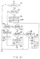
- the library controller 1 determines if the source element address of the command is not higher than 1000 (FIG.27, step S201). If the source element address is not higher than 1000, the command proceeds with the procedure in and after step S211 in FIG.28. If the source element address is higher than 1000, it is compared with the address 1001 (step S202).
- step S203 If the source element address of the command is 1001, the command proceeds with the procedure in and after step S231 in FIG.29. Unless it is 1001, it is compared with the address 1002 (step S203). If the source element address is 1002, the command proceeds with the procedure in and after step S251 in FIG.31. Unless it is 1002, it is compared with 1003 (step S204).
- the command proceeds with the procedure in and after step S271 in FIG.32. Unless it is 1003, it is compared with the address 1005 (step S205). If the source element address is 1005, the command proceeds with the procedure in and after step S291 in FIG.33. Unless it is 1005, no corresponding address exists in TAU 0. Accordingly, the same error procedure is executed as in LUN 0 (step S206), the error recovery procedure is executed (step S207) and the process is terminated.
- step S201 if the source element address is not higher than 1000, it is determined if the destination address is not higher than 1000 (FIG.28, step S211). If the destination element address is not higher than 1000, the recording medium is transferred in TAU 0 due to the command being restricted to TAU 0 (step S212) and the process is terminated.
- step S211 if the destination element address is higher than 1000, it is compared with 1001 (step S213). If the destination element address is 1001, this command represents the recording medium transfer from TAU 0 to DAU 0. The flag of the control data 'DAU 0 - TAU 0' is set (step S214), LUN and the source element address of the command are stored in the control data 'DAU 0 - TAU 0' (step S215) and the process is terminated.
- step S213 unless the destination element address is 1001, it is compared with the address 1002 (step S216). If the destination element address is 1002, this command represents the recording medium transfer from TAU 0 to LAU.
- the flag of the control data 'TAU 0 - LAU' is set (step S217), LUN and the source element address of the command are stored in the control data 'TAU 0 - LAU' (step S215) and the process is terminated.
- step S216 unless the destination element address is 1002, it is compared with the address 1003 (step S218). If the destination element address is 1003, this command represents the recording medium transfer from TAU 0 to RAU.
- the flag of the control data 'RAU - TAU 0' is set (step S219), LUN and the source element address of the command are stored in the control data 'RAU - TAU 0' (step S215) and the process is terminated.
- step S2128 unless the destination element address is 1003, it is compared with the address 1005 (step S220). If the destination element address is 1005, the destination corresponds to CAS 5 in RAU or in LAU. Then, the recording medium is transferred to CAS 5 (step S221), and the process is terminated. At this point, the same procedure is executed in FIG.18, step S91 to determine which CAS 5 in RAU or in LAU is to be used.
- step S220 unless the destination element address is 1005, no corresponding address exists in TAU 0.
- the error procedure is executed (step S206), the error recovery procedure is executed (step S207) and the process is terminated.
- step S202 if the source element address is 1001, it is confirmed if the flag of the control data 'DAU 0 - TAU 0' is set (FIG.29, step S231). Unless the flag is set, the error procedure is executed due to an unidentified source frame (step S206), the error recovery procedure is executed (step S207) and the process is terminated.
- step S232 it is determined if the destination element address is not higher than 1000 (step S232). If the destination element address is not higher than 1000, the destination corresponds to the cell 7 or MTU 4 in TAU 0.
- step S233 the flag of the control data 'DAU 0 - TAU 0' is reset (step S233), the recording medium is transferred from the source element address in LUN, stored in the control data, to the destination element address (step S234) and the process is terminated.
- step S232 if the destination element address is higher than 1000, it is compared with the address 1001 (step S235). If the destination element address is 1001, the error procedure is executed since it is same as the source element address (step S206), the error recovery procedure is executed (step S207) and the process is terminated.
- step S236 Unless the destination element address is 1001, it is compared with the address 1002 (step S236). If the destination element address is 1002, this command represents the recording medium transfer to LAU through TAU 0.
- step S237 the flag of the control data 'TAU 0 - LAU' is set (step S237), and the flag of the control data 'DAU 0 - TAU 0' is reset (step S238).
- LUN and the source element address of the control data 'DAU 0 - TAU 0' are copied to the control data 'TAU 0 - LAU' (step S239) and the process is terminated.
- step S236 unless the destination element address is 1002, it is compared with the address 1003 (FIG.30, step S241). If the destination element address is 1003, this command represents the recording medium transfer to RAU through TAU 0.
- step S242 the flag of the control data 'RAU - TAU 0' is set (step S242) and the flag of the control data 'DAU 0 - TAU 0' is reset (step S243).
- LUN and the source element address of the control data 'DAU 0 - TAU 0' are copied to the control data 'RAU - TAU 0' (step S239) and the process is terminated.
- step S241 unless the destination element address is 1003, it is compared with the address 1005 (step S244). If the destination element address is 1005, this command represents the recording medium transfer to CAS 5 through TAU 0.
- step S245 the flag of the control data 'DAU 0 - TAU 0' is reset (step S245), the recording medium is transferred from the destination element address in LUN of the control data to CAS 5 (step S246) and the process is terminated.
- step S91 is executed to determine which CAS 5 in RAU or in LAU is to be used.
- step S244 unless the destination element address is 1005, no corresponding address exists in TAU 0.
- the error procedure is executed (step S206), the error recovery procedure is executed (step S207) and the process is terminated.
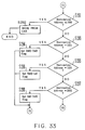
- step S203 if the source element address is 1002, it is confirmed if the flag of the control data 'TAU 0 - LAU' is set (FIG.31, step S251). Unless the flag is set, the error procedure is executed due to an unidentified source frame (step S206), the error recovery procedure is executed (step S207) and the process is terminated.
- step S252 If the flag of the control data 'TAU 0 - LAU' is set, it is determined if the destination element address is not higher than 1000 (step S252). If the destination element address is not higher than 100, the destination corresponds to the cell 7 or MTU 4 in TAU 0.
- step S253 the flag of the control data 'TAU 0 - LAU' is reset (step S253), the recording medium is transferred from the source element address in LAU stored in the control data to the destination element address in TAU 0 (step S254) and the process is terminated.
- step S252 if the destination element address is higher than 1000, it is compared with the address 1001 (step S255). If the destination element address is 1001, this command represents the recording medium transfer to DAU 0 through TAU 0.
- step S256 the flag of the control data 'DAU 0 - TAU 0' is set (step S256), and the flag of the control data 'TAU 0 - LAU' is reset (step S257).
- LUN and the source element address of the control data 'TAU 0 - LAU' are copied to the control data 'DAU 0 - TAU 0' (step S239) and the process is terminated.
- step S255 unless the designation element address is 1001, it is compared with the address 1002 (step S258). If the destination element address is 1002, the error procedure is executed since it is same as the source element address (step S206), the error recovery procedure is executed (step S207) and the process is terminated.
- step S258 unless the destination element address is 1002, it is compared with the address 1003 (step S259). If the destination element address is 1003, this command represents the recording medium transfer to RAU through TAU 0.
- step S260 the flag of the control data 'RAU - TAU 0' is set (step S260), and the flag of the control data 'TAU 0 - LAU' is reset (step S261).
- LUN and the source element address of the control data 'TAU 0 - LAU' are copied to the control data 'RAU - TAU 0' (step S239) and the process is terminated.
- step S259 unless the destination element address is 1003, it is compared with the address 1005 (step S262). If the destination element address is 1005, this command represents the recording medium transfer to CAS 5 through TAU 0.
- step S263 the flag of the control data 'TAU 0 - LAU' is reset (step S263), the recording medium is transferred from the source element address in LUN of the control data to CAS 5 (step S264) and the process is terminated.
- step S91 is executed to determine which CAS 5 in RAU or in LAU is to be used.
- step S262 unless the destination element address is 1005, no corresponding address exists in TAU 0.
- the error procedure is executed (step S206), the error recovery procedure is executed (step S207) and the process is terminated.
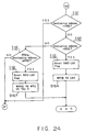
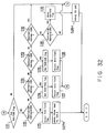
- step S204 if the source element address is 1003, it is confirmed if the flag of the control data 'RAU - TAU 0' is set (FIG.32, step S271). Unless the flag is set, the error procedure is executed due to an unidentified source address (step S206), the error recovery procedure is executed (step S207) and the process is terminated.
- step S272 it is determined if the destination element address is not higher than 1000 (step S272). If the destination element address is not higher than 1000, the destination corresponds to the cell 7 or MTU 4 in TAU 0.
- step S273 the flag of the control data 'RAU - TAU 0' is reset (step S273), the recording medium is transferred from the source element address in LUN, stored in the control data, to the destination element address in TAU 0 (step S274) and the process is terminated.
- step S272 if the destination element address is higher than 1000, it is compared with the address 1001 (step S275). If the destination element address is 1001, this command represents the recording medium transfer to DAU 0 through TAU 0.
- step S276 the flag of the control data 'DAU 0 - TAU 0' is set (step S276), and the flag of the control data 'RAU - TAU 0' is reset (step S277).
- LUN and the source element address of the control data 'RAU - TAU 0' are copied to the control data 'DAU 0 - TAU 0' (step S239) and the process is terminated.
- step S275 unless the destination element address is 1001, it is compared with the address 1002 (step S278). If the destination element address is 1002, this command represents the recording medium transfer to LAU through TAU 0.
- step S279 the flag of the control data 'TAU 0 - LAU' is set (step S279), and the flag of the control data 'RAU- TAU 0' is reset (step S280).
- LUN and the source element address of the control data 'RAU - TAU 0' are copied to the control data 'TAU 0 - LAU' (step S239) and the process is terminated.
- step S278 unless the destination element address is 1002, it is compared with the address 1003 (step S281). If the destination element address is 1003, the error procedure is executed since it is same as the source element address (step S206), the error recovery procedure is executed (step S207) and the process is terminated.
- step S281 unless the destination element address is 1003, it is compared with the address 1005 (step S282). If the destination element address is 1003, this command represents the recording medium transfer to CAS 5 through TAU 0.
- step S283 the flag of the control data 'RAU - TAU 0' is reset (step S283), the recording medium is transferred from the source element address in LUN of the control data to CAS 5 (step S284) and the process is terminated.
- step S284 the same procedure as in FIG.18 step S91 is executed to determine which CAS 5 in RAU or in LAU is to be used.
- step S282 unless the destination element address is 1005, no corresponding address exists in TAU 0.
- the error procedure is executed (step S206), the error recovery procedure is executed (step S207) and the process is terminated.
- step S205 if the source element address is 1005, it is determined if the destination element address is not higher than 1000 (FIG.33, step S291). If the destination element address is lower than 1000, the destination corresponds to the cell 7 or MTU 4 in TAU 0. The recording medium is transferred from CAS 5 to the destination element address in DAU 0 (step S292) and the process is terminated.
- step S291 if the destination element address is higher than 1000, it is compared with the address 1001 (step S293). If the destination element address is 1001, the destination corresponds to DAU 0. The flag of the control data 'DAU 0 - TAU 0' is set (step S294), LUN and the source element address of CAS 5 are stored in the control data (step S215) and the process is terminated.
- step S293 unless the destination element address is 1001, it is compared with the address 1002 (step S295). If the destination element address is 1002, the destination corresponds to LAU.
- the flag of the control data 'TAU 0 - LAU' is set (step S296), LUN and the source element address of CAS 5 are stored in the control data (step S215) and the process is terminated.
- step S295 unless the destination element address is 1002, it is compared with the address 1003 (step S297). If the destination element address is 1003, the destination corresponds to RAU. The flag of the control data 'RAU - TAU 0' is set (step S298), LUN and the source element address of CAS 5 are stored in the control data (step S215) and the process is terminated.
- step S297 unless the destination element address is 1003, the error procedure is executed (step S206), the error recovery procedure is executed (step S207) and the process is terminated.
- the process in LUN 3 is basically similar to the process in LUN 0.
- the library controller 1 initially determines if the source element address of the command is lower than 0100 (FIG.34, step S301). If the source element address is lower than 0100, it is determined if the destination element address is lower than 0100 (step S302). If the destination element address is lower than 0100, the recording medium is transferred in LAU due to the command being restricted to LAU (step S303) and the process is terminated.
- step S302 if the destination element address is not lower than 0100, it is determined if it is 0100 (step S304). If the destination element address is 0100, this command represents the recording medium transfer from LAU to TAU 0. LUN and the source element address of the command are stored in the control data 'TAU 0 - LAU' (step S305), the flag is set (step S306) and the process is terminated.
- step S304 unless the destination element address is 0100, it is compared with the address 0101 (step S307). If the destination element address is 0101, this command represents the recording medium transfer from LAU to DAU 0. Then, LAU and the source element address of the command are stored in the control data 'DAU 0 - TAU' (step S308), the flag of the control data is set (step S309) and the process is terminated.
- step S307 unless the destination element address is 0101, it is compared with the address 0102 (step S310). If the destination element address is 0102, this command represents the recording medium transfer from LAU to RAU. LUN and the source element address of the command are stored in the control data 'RAU - LAU' (step S311), the flag of the control data is set (step S312) and the process is terminated.
- step S310 unless the destination element address is 0102, it is determined if it is not lower than 0103 and not higher than 010A (step S313). With case the destination element address is within this range, the destination corresponds to MTU 4 in TAU 0. With reference to the address table in FIG.11, the recording medium is transferred from LAU to MTU 4 in TAU 0 (step S314) and the process is terminated.
- step S313 if the destination element address is lower than 0103 or higher than 010A, no corresponding address exists in LAU 0.
- the same error procedure as in LUN 0 is executed (FIG.36, step S337), the error recovery procedure is executed (step S338) and the process is terminated.
- step S301 if the source element address is not lower than 0100, it is determined if it is 0100 (FIG.35, step S321). If the source element address is 0100, the destination element address is compared with the address 0100 (step S322). If the destination element address is lower than 0100, it is confirmed if the flag of the control data 'TAU 0 - LAU' is set (step S323).
- this command represents the recording medium transfer from TAU 0 to LAU.
- the flag of the control data 'TAU 0 - LAU' is reset (step S324), the recording medium is transferred from the source element address in LUN, stored in the control data, to the destination element address in LAU (step S325) and the process is terminated.
- step S322 in case the destination element address is not lower than 0100 and the flag is not set in step S323, the command proceeds with the procedure in and after step S337 in FIG.36.
- step S321 unless the source element address is 0100, it is compared with the address 0101 (step S326). If the source element address is 0101, the destination element address is compared with the address 0100 (step S327). If the destination element address is lower than 0100, it is confirmed if the flag of the control data 'DAU 0 - LAU' is set (step S328).
- this command represents the recording medium transfer from DAU 0 to LAU.
- the flag of the control data is reset (step S329), the recording medium is transferred from the source element address in LUN, stored in the control data, to the destination element address in LAU (step S325) and the process is terminated.
- step S327 in case the destination element address is not lower than 0100 and the flag is not set in step S328, the command proceeds with the procedure in and after step S337 in FIG.36.
- step S326 unless the source element address is 0101, it is compared with the address 0102 (FIG.36, step S331). If the source element address is 0102, the destination element address is compared with the address 0100 (step S332). If the destination element address is lower than 0100, it is confirmed if the flag of the control data 'RAU - LAU' is set (step S333).
- this command represents the recording medium transfer from RAU to LAU.
- the flag of the control data 'RAU - LAU' is reset (step S339), the recording medium is transferred from the source element address in LUN, stored in the control data, to the destination element address in LAU (step S325) and the process is terminated.
- step S332 in case the destination element address is not lower than 0100 and the flag is not set in step S333, the command proceeds with the procedure in and after step S337.
- step S331 unless the source element address is 0102, it is determined if it is not lower than 0103 and not higher than 010A (step S334). If the source element address is within this range, the source corresponds to MTU 4 in TAU 0.
- step S335 the destination element address is compared with the address 0100 (step S335). If the destination element address is lower than 0100, with reference to the address table in FIG.11, the recording medium is transferred from MTU 4 in TAU 0 to LAU (step S336) and the process is terminated. If the destination element address is not lower than 0100 in step S335, the command proceeds with the procedure in and after step S337.
- the library controller 1 receives the MOVE command for LUN 1 (FIG.13, step S11), and starts processing for LUN 1 (step S18).
- step S71 Since the source element address of the command is 1000, the determination result in FIG.17, step S71 is YES. And, since the destination element address of the command is FF02, the destination result in FIG.18, step S86 is YES.
- step S11 receives the MOVE command for LUN 2 (step S11), and starts processing for LUN 2 (step S21). Since the source element address of the command is 1001, the determination result in FIG.27, step S202 is YES. Since the destination element address is 0001, the determination result in FIG.29, step S232 is YES.
- the library controller 1 resets the flag of the control data 'DAU 0 - TAU 0' (step S233).
- the library controller 1 directs the ACC 6 to mount the recording medium from the address 1000 in DAU 0 to MTU 4 at the address 0001 in TAU 0 (step S234).
- the library controller 1 receives the MOVE command for LUN 0 (step S11), and starts processing for LUN 0 (step S15).Since the source element address of the command is 0002, the determination result in FIG.14, step S31 is YES. Since the destination element address is 0104, the determination result in step S43 is YES.
- the library controller 1 refers to the address table in FIG.11, and directs the ACC 6 to mount the recording medium from the address 0002 in RAU to MTU 4 at the address 0001 in TAU 0 (step S44).
- the library controller 1 receives the MOVE command for LUN 1 (step S11), and starts processing for LUN 1 (step S18). Since the source element address of the command is 0000, the determination result in FIG.17, step S71 is YES. Since the destination element address is FF05, the determination result in FIG.18, step S90 is YES.
- the library controller 1 directs the ACC 6 to transfer the recording medium from the address 0000 in DAU 0 to CAS 5 in RAU (step S91).
- the library controller 1 receives the MOVE command for LUN 1 after the operator sets DAU 0 to the NOT READY state (step S11), and determines that the determination result in step S17 is NO.
- the library controller 1 returns the NOT READY response to the host computer 21 (step S14).
- the library controller 1 when the library controller 1 receives the MOVE command for a logical unit in the READY state other than LUN 1, the library controller 1 starts processing for the logical unit (steps S15, S21, S24).
- the source element address or the destination element address of the MOVE command corresponds to the existing real element.
- the address 0001 of CAS 5 and the addresses FF05 and 1005 of the import/export element 42 can be designated to the source element address during the error recovery procedure. Further, these addresses can be used for the destination element address.
- the library device 22 is logically divided in units of frame. Regardless of the above examples, any division unit can be defined as a logical unit. It is not necessary to use all of the virtual elements shown in FIG.6. Any number of virtual elements can be eliminated or added.
- control object of the present invention is not necessarily limited to the library device. Similar types of control methods can be applied to other logically dividable devices or systems.
- the present invention can control the library device by means of the general-use interface, such as SCSI.
- the effects described below are obtained when the library device is controlled through SCSI.
- the present invention can provide the control method under the command of the medium changer device in SCSI, as defined by ANSI.
- a partial NOT READY state in the library device cannot be defined when the library device is wholly controlled as one logical unit. If the library device is virtually divided, the NOT READY state can be defined in units of logical units.
- the address can be uniquely defined irrespective of the condition of the frame assignment in each model. Accordingly, the element addresses can be assigned in the unit during manufacture.
Abstract
The library device is divided into a plurality
of logical units (LUN0...LUN3) in units of frames,and a transport
element, an import/export element, a data transfer
element etc, are virtually provided in each logical
unit. The library controller (12) receives commands for
each logical unit containing a virtual element address
and processes these commands as being linked.
Description
The present invention relates to a technology for
controlling a large-scale library device by using a
small-scale host computer, more specifically, to a
library control device for logically dividing a
library device into a plurality of logical units and
controlling it, and a method thereof.
Recently, a library device is put to commercial
use in various fields for automatically performing
import/export, storage, read/write of a recording
medium and the like. As such a recording medium, an
optical disk, compact disk read only memory (CD-ROM),
magnetic tape or so on, is utilized.
FIG.1A is a schematic drawing of the conventional
large-scale magnetic tape library. In general, a large
scale magnetic tape library set (MTL) consists of
frames for each function. The magnetic tape library
in FIG.1A comprises four frames, RAU, DAU 0, TAU 0,
and LAU storing MT cartridges, and is controlled by
the library controller 1 in the frame ACU. FIG.1B is
a schematic diagram of in the internal configuration
of the subsystem of the magnetic tape library.
RAU is a frame located on the right side of the
subsystem and is a frame comprising a cartridge access
station (CAS) 5, accessor (ACC) 6, and a plurality of
cells (CELLs) 7. CAS 5 is a special cell for
importing/exporting a recording medium to the library
device and is operable in the online (READY) state.
ACC 6 is a robot for transporting the recording medium
within the library device, and the cells 7 are slots
for storing recording media.
ACC 6 can move arbitrarily among the frames, and
transports the recording medium to and from each of
CAS 5, CELLs 7, DEE 2 and MTU 4, according to an
instruction from the library controller 1.
In such a conventional magnetic tape library as
described above, the addresses of the CELLs 7, DEE 2,
CAS 5, and MTU 4, are controlled by a combination of
the frame number with the addresses within that frame.
In RAU, DAU 0, TAU 0, and LAU, for example, the frame
numbers 01, 02, 03, and 04 are allocated to each
frame, and addresses of three bytes are utilized for
each frame.
Further to this, it has been recently requested
that a large-scale library device be controlled by a
small-scale host computer such as a personal computer
or work station. In this case, it is necessary to
connect the host computer and the library device with
a general-use interface such as the small computer
system interface (SCSI-2) defined in the American
National Standard Institute (ANSI) X3B10 for
controlling the library device as a medium changer
device specified in SCSI-2. In this case, such
problems are raised as described below:
Conventionally, it was mandatory to write cell
addresses address on completion of a model, or to
write cell addresses from the viewpoint of a model to
be used. Cell addresses can be determined after
completion of a library device set, but it is
necessary to modify addresses whenever frames are
added. Accordingly, the same problem will be raised
as described above in (4), in the case of address
representation.
As described by items (1) to (5) above, it is
extremely difficult to put the library device under
the control of SCSI, in which applicable addresses are
restricted, because recent large-scale library devices
are equipped with much more advanced facilities than
the conventional medium changer device in SCSI-2.
An embodiment of the present invention may provide
a library control device for controlling a large-scale
library device by means of such a general-use
interface as SCSI and a method thereof.
In the first aspect of the present invention, the
library control device comprises a memory unit and a
control unit. The memory unit stores logical structure
information representing the configuration of the
library device divided into a plurality of logical
units, each suitable for independent control. The
control unit controls the operations of the library
device using the logical structure information.
Each frame of the library device is, for example,
regarded as one logical unit in SCSI, and the library
device is divided into as many logical units as
frames. Accordingly, even in such a large-scale
library device with more addresses than are available
using 2 bytes, each division of it is independently
controllable as a medium changer device in SCSI.
In the logical structure information stored in
the memory unit, 2 bytes of element addresses such as
cell addresses are written for each of the logical
units.
The host system issues the medium transfer
commands to the medium changer device and directs the
control unit to control the library device, and it is
necessary to assign element addresses of an accessor,
a transfer source, and a transfer destination, when
the command is issued.
Accordingly, a virtual transport element is
provided to logical units containing no accessor(ACC),
and the element addresses are assigned. These element
addresses correspond to an address of the real ACC.
Thus, the medium transfer command can be issued even
to logical units containing no ACCs.
Further, virtual import/export elements are
provided with the function to import/export a
recording medium between two logical units, so as to
enable commands for recording medium transfer, and
element addresses are assigned to these virtual
elements.
The control unit processes the commands to
different logical units in association with a check
of the logical structure information, on receipt of
a command for each logical unit from the host system.
Based on the result of this process, the control
signal is issued to control the library device.
As explained above, the logically divided library
device can be controlled in a unified manner by
providing virtual functional elements which do not
exist in each of the library devices, in cooperation
with the SCSI interface.
In the second aspect of the present invention,
the library device comprises a storage unit and a
control unit. The storage unit stores a plurality of
recording media, and the control unit controls the
library device by dividing it into a plurality of
logical units, each suitable for independent control.
In the third aspect of the present invention, the
control device comprises a memory unit and a control
unit. The memory unit stores logical structure
information representing the configuration of a
control object divided into a plurality of logical
units, each suitable for independent control. The
control unit controls the control object using the
logical structure information.
Still further, in the fourth aspect of the
present invention, the host system comprises a memory
unit and a command issuing unit. The memory unit
stores logical structure information representing the
configuration of the library device divided into a
plurality of logical units each suitable for
independent control. The command issuing unit issues
commands to each of the plurality of logical units.
Reference is made, by way of example, to the
accompanying drawings in which:
An embodiment of the present invention will now
be described in detail hereinafter with reference to
the attached drawings.
FIG.2A shows a principle of the library control
device embodying the present invention. The
library control device comprises a memory unit 11 and
a control unit 12.
The memory unit stores the logical structure
information representing the configuration of the
library device, divided into a plurality of logical
units each suitable for independent control. The
control unit controls the operations of the library
device using the logical structure information.
Each frame of the library device is, for example,
considered to be one logical unit in SCSI and the
library device is divided into as many logical units
as there are frames. Accordingly, even in such a
large-scale library device with more addresses than
are available using 2 bytes, each division of it is
independently controllable as a medium changer device
in SCSI.
In the logical structure information stored in
the memory unit 11, the 2 bytes of the element
addresses such as cell addresses are written for each
of the logical units. LUN represents a logical unit
number and the letter (h) in the column for the
element address shows that the addresses are written
as hexadecimal numbers.
The host system issues a medium transfer command
to the medium changer device and directs the control
unit 12 to control the library device, and it is
necessary to assign element addresses of the accessor,
the transfer source, and the transfer destination,
when the command is issued.
Contrary to this, in the library device in
FIG.2A, no accessors are included in either LUN 1 or
LUN 2.
Accordingly, as shown by a dotted line, a virtual
accessor is provided in these logical units and an
element address is assigned to the virtual accessor.
This element address is made to correspond to an
address of a real accessor. Thus, the medium transfer
command can be issued to both LUN 1 and LUN 2.
Further, virtual import/export elements with the
function of transferring a recording medium between
two adjoining or remote logical units are provided so
as to facilitate the recording medium transfer between
different logical units, and element addresses are
assigned to these virtual elements. As indicated by
arrows, the host system can command a transfer between
different logical units by issuing two linked commands
to a pair of import/export elements corresponding to
each other.
In the case of a command to transfer a medium
from LUN 0 to LUN 1, for example, a first command is
initially issued to LUN 0 to transfer the medium to
the address 0100, followed by a second command to LUN
1 to transfer the medium from the address FF01.
The control unit 12 processes the commands to
different logical units in association with a check
of the logical structure information, on receipt of
the command from the host system, for each logical
unit. Based on the result of this process, the control
signal is issued to control the library device.
On receiving the first and second commands, for
example, the destination address 0100 of the first
command is recognized to correspond to the source
address FF01 of the second command, by referring to
the logical structure information. At this time, it
is considered that the recording medium is transferred
between these virtual elements, and the library device
is controlled to transfer the recording medium
directly from the source element address of the first
command, to the destination element address of the
second command.
In such a manner as described above, the
logically divided library device can be controlled in
a unified manner by providing virtual functional
elements which do not exist in each of the library
devices, in co-operation with the SCSI interface.
Further, the NOT READY state can be set in each
of the logical units by logically dividing the library
device. In the case of the number of frames of the
library device being increased, the added frames can
be defined as new ones, and no revision is required
to the addresses of the existing elements.
Accordingly, predetermined addresses can be stored
even though the model is structurally modified or
upgraded, without rewriting addresses represented on
manufacture.
The memory unit 11 in FIG.2A, for example,
corresponds to the memory 33 in FIG.4 described later,
the control unit 12 corresponds to the interface 31,
34, and processing unit 32, and the logical structure
information corresponds to the address information
shown in FIGS.7, 8, 9,10 and 11.
In the present embodiment, the library controller
1 (FIG.1A) of the library device interprets a command
set for the medium changer device in SCSI to control
the library device, by association with the library
management software of the upper host computer.
Therefore, the library controller 1 serves as the SCSI
controller. In order to increase the number of cell
addresses available to the medium changer device, the
library device is logically divided into a plurality
of logical units, not treated as one logical unit as
in SCSI-2.
In one example of the preferred embodiments as
described below, a logical unit number (LUN) in SCSI
is assigned to each of the frames comprising the
library device. Thus, 2 byte addresses can be defined
for each frame, and it is possible to deal with the
large-scale library device with more cell addresses
than are available using 2 bytes.
The host computer issues to the library
controller 1 one or more commands directing linking
operations among a plurality of logical units or
frames under control, resulting in controlling a
library device set. In order to enable linking
operations in different logical units, virtual cells
are provided, as described below, in each frame:
In the above items (a) to (c), to provide virtual
cells means to set cell addresses representing dummy
functions. The library controller 1 recognizes whether
or not the command issued from the host computer to
each LUN is a transfer command necessary to be linked
with other LUNs.
When the command is issued to such specific
virtual cells as described in the above (a) to (c),
the library controller 1 stores the command without
executing any operation, until a series of commands
have been issued to terminate the linking operation.
FIG.2B is a flowchart of the control process in
a plurality of logical units performed by the library
controller 1. On starting the process, the library
controller 1 receives a command for one of the logical
units from the host computer (step S1), followed by
the determination of whether or not any virtual cell
address is included in the received command (step S2),
and the received command is temporarily stored if such
addresses are included (step S3).
Further, a decision is made as to whether or not
a series of stored commands are executable (step S4).
These commands are judged executable if the addresses
of the virtual cells included in these commands
constitute a corresponding pair, and if the physical
transfer source and destination of the recording
medium can be specified. On the other hand, these
commands are judged unexecutable if virtual cell
addresses which do not correspond to any of the
addresses of existing real units remain in the
commands.
If a series of commands are judged unexecutable,
the following command is fed from the host computer
(step S1), and the iterative process in and after step
S2 is performed. If a series of commands are
executable, these commands are interpreted together
to operate the library device (step S5), and the
process is terminated. In step S2, the command is
instantly executed to terminate the process, when it
is determined that no addresses of virtual cells are
included in the command.
In such a manner as described above, one frame
can be regarded as one logical unit controllable in
SCSI, by providing appropriate virtual cells in each
frame. Accordingly, the host computer can issue a
medium transfer command to each frame. Further, it is
made possible to set the address of the virtual cell
in correspondence with a real function and to control
the logically divided library device by interpreting
and executing a series of mutually related commands.
In addition, the library device can inform the
host computer of the NOT READY state in each LUN when
it is required to set a frame into the NOT READY
state, since the host computer individually controls
each of the logical units.
FIG.3 shows the structure of the control system
in the large-scale library device as one of the
preferred embodiments. The library device 22 in FIG.3,
corresponding to the library device in FIGS.1A and 1B,
operates on receipt of the commands from the host
computer 21 having a SCSI interface.
In the library device described above, LUN 0, LUN
1, LUN 2, and LUN 3 are assigned to the four frames
RAU, DAU 0, TAU 0, and LAU, in that order, and each
frame is recognized as an independent logical unit.
In some cases as described below, each frame is
identified in accordance with the LUN form. The frame
RAU, for example, is only represented as LUN 0.
In FIG.3, the accessor 6 in LUN 0 and LUN 3 is
defined as the transport element (TR) in SCSI, and the
hexadecimal address 0000 is assigned. In this case,
an element in SCSI means a cell in the broader sense,
including the real cell 7.
8 sets of MTU 4 in LUN 2 are all defined as data
transfer elements (DT) to which the addresses 0000 to
0007 are assigned, and the cells 7 in LUN 2 are
defined as the storage elements to which the addresses
0008 to 1000 are assigned.
FIG.4 is a structural chart of the library
controller 1 shown in FIG.3. The library controller
1 comprises a SCSI input/output interface (I/O) 31,
processing unit 32, memory 33, and input/output
interface (I/O) 34 for each frame. These elements are
connected by means of a bus 35.
The interface 31 receives the commands from the
host computer 21 and transmits the response back to
the host computer 21. The memory 33 includes a read
only memory (ROM) for storing data and programs and
a random access memory (RAM) for processing.
The processing unit 32 executes the programs
stored in the memory 33 using the data stored in the
memory 33. Based on the result, the command is
interpreted to instruct an operation in each frame.
The interface 34 sends a control signal on the basis
of the control from the processing unit 32. In this
manner, the library controller 1 executes the commands
from the host computer 21 to operate the library
device 22.
FIG.5 shows a data configuration of the medium
transfer command (MOVE command) in SCSI, transferred
to the library controller 1. In the MOVE command in
FIG.5, CDB 0 represents the operation code
corresponding to the medium transfer, and CDB 1 shows
the LUN of the logical unit of the command issue
object.
As described above, the MOVE command in SCSI can
direct the medium transfer only between the elements
in a specified logical unit. The MOVE command,
however, cannot direct the medium transfer between
different logical units. Additionally, in the library
device 22 in FIG.3, no accessor is included in LUN 1
and LUN 2, and no definition is given to the transport
element. Therefore, the MOVE command cannot be issued
to these logical units without some modification.
Accordingly, as shown in FIG.6, the host computer
21 provides an appropriate virtual transport element,
virtual import/export element, and virtual data
transfer element, and issues the MOVE command
including the addresses of these virtual elements.
In FIG.6, the virtual transport element 41 and
the virtual import/export element 42 are provided to
LUN 1 and LUN 2 having no ACC 6 and CAS 5. The
transport element 41 and the import/export element 42
respectively correspond to the real ACC 6 and CAS 5.
The addresses 1004 and 1005 are assigned
respectively to the transport element 41 and the
import/export element 42 in LUN 2 and the addresses
FF04 and FF05 are assigned respectively to the
transport element 41 and the import/export element 42
in LUN 1.
Thus, by using the virtual transport element 41,
the host computer 21 can utilize the transport element
address (CDB 2 and CDB 3) of the MOVE command to cover
LUN 1 and LUN 2, and can issue a MOVE command to these
frames.
Further, by using the virtual import/export
element 42, the host computer can utilize addresses
corresponding to CAS 5 in other frames, as the source
element address (CDB 4 and CDB 5) or the destination
element address (CDB 6 and CDB 7) of the MOVE command
to LUN 1 and LUN 2. As a result, the recording medium
transfer between CAS 5 and LUN 1 or LUN 2 can be
directly commanded to LUN 1 or LUN 2. 8 sets of
virtual data transfer elements corresponding to 8 sets
of MTU 4 in LUN 2 are provided to LUN 0, LUN 1, and
LUN 3 which have no MTU 4. The addresses 0103 to 010A
are assigned to the data transfer elements 43 in LUN
0 and LUN 3, and the addresses FF06 to FF0D to the
data transfer elements 43 in LUN 1.
Thus, by using the virtual data transfer element
43, the host computer 21 can utilize addresses
corresponding to MTU 4 in LUN 2, as the source element
address or the designation element address of the MOVE
command to LUN 0, LUN 1, and LUN 3. As a result, the
recording medium transfer between MTU 4 and LUN 0, LUN
1, or LUN 3 can be directly commanded to LUN 0, LUN
1, or LUN 3.
In order to enable the recording medium to be
imported/exported between arbitrary frames, a virtual
import/export element 44 is provided for all frames.
The addresses 0100, 0101, and 0102 are assigned to the
3 sets of import/export elements 44 in LUN 0, and the
addresses FF01, FF02 and FF03 to the 3 sets of
import/export elements in LUN 1.
Further, the addresses 1001, 1002 and 1003 are
assigned to the 3 sets of import/export elements 44
in LUN 2, and the addresses 0100, 0101 and 0102 to the
3 sets of import/export elements 44 in LUN 3.
In these import/export elements, the element 44
at the address 0100 in LUN 0 corresponds to the
element 44 at the address FF01 in LUN 1. The virtual
recording medium transfer can be performed between
these elements.
Accordingly, the host computer 21 can direct the
recording medium transfer between LUN 0 and LUN 1, by
applying the addresses of these import/export elements
44 to the source element or the destination element
of the MOVE command.
Similarly, the import/export element 44 at the
address 0101 in LUN 0 corresponds to the import/export
element 44 at the address 1003 in LUN 2, and the
import/export element 44 at the address 0102 in LUN
0 to the import/export element 44 at the address 0102
in LUN 3.
The import/export element 44 at the address FF02
in LUN 1 corresponds to the import/export element 44
at the address 1001 in LUN 2, the import/export
element 44 at the address FF03 in LUN 1 corresponds
to the import/export element 44 at the address 0101
in LUN 3, and the import/export element 44 at the
address 1002 in LUN 2 corresponds to the import/export
element 44 at the address 0100 in LUN 3.
In such a manner, through the virtual
import/export element 44, the host computer 21 can
utilize addresses corresponding to other frames as the
source element or the destination element of the MOVE
command, and the recording medium transfer can be
directed between arbitrary frames.
FIGS.7 to 10 are tables showing the addresses of
each of the real and the virtual elements. FIGS. 7,
8, 9, 10 show the element addresses of LUN 0, LUN 1,
LUN 2 and LUN 3, respectively.
In these FIGS, the real function represents the
real element shown by the solid lines in FIG.6, and
the virtual element represents the virtual element
shown by the dotted lines in FIG.6. For example, the
notation import/export (RAU - DAU 0) in FIG.7
represents that this is the element for virtually
importing/ exporting the recording medium between RAU
and DAU. The letter (h) in the element address shows
that the addresses are given as hexadecimal numbers.
The virtual element with the symbol '*'
corresponds to the element 44 for virtually
importing/exporting the recording medium between two
frames in adjoining positions, and the virtual element
with the symbol '**' is the element 44 for virtually
importing/exporting the recording medium between two
frames in remote positions.
Further, the virtual element with the symbol
'***' corresponds to the transport element 41, the
virtual element with the symbol '****' corresponds to
the import/export element 42, and the virtual element
with the symbol '*****' corresponds to the data
transfer element 43.
The data transfer elements 43 in LUN 0, LUN 1,
and LUN 3 are in one-to-one correspondence with the
addresses of MTU 4 in LUN 2, and the relation is shown
in the address reference table in FIG.11. In FIG.11,
the symbol MTU (i) (i=0, 1, 2,....7) corresponds to
the addresses 0000 to 0007 in FIG.3, respectively.
The host computer 21 and the library controller
1 store the LUN and a part or all of the address
information shown in FIGS.7 to 11 as the management
information, and control the library device 22 with
reference to the information.
As described above, on the basis of the
characteristics of the large-scale library device that
the number of real transport elements, data transfer
elements, and import/export elements is extremely
small compared with the number of medium storage
elements, the present embodiment divides the whole
library device 22 into frames as logical units in
SCSI.
Further, by providing the virtual transfer
elements 41, import/ export elements 42 and 44, and
data transfer elements 43, the divided large-scale
library device is controlled for the recording medium
transfer between logical units. Detailed explanation
will be given in the following about the control
method.
A general operation of the library deice 22 is
summarized as follows:-
The application program executed in the host
computer 21 specifies the volume name of the recording
medium, and informs the library management software
in the host computer 21 of the operating procedure of
the library device 22. The volume name, for example,
is given in a combination of six letters/ figures. The
operating procedure includes the action of mounting
a recording medium in the MTU 4, the exporting action
from DEE 2 or CAS 5 out of the library device 22, and
the like.
Two examples are given in the information for a
transfer inside the library device 22; that the
destination address is explicitly informed, and that
the destination address is not informed, for the
purpose of utilizing the automatic address assignment
by the library management software.
The library management software calculate from
the informed volume name an element address of the
library device 22 in which the objective recording
medium is stored. In addition, the library management
software determines the destination element address
of the recording medium, in accordance with the
operation procedure informed by the application
program. Depending on the operation procedure,
however, there are some cases when no recording medium
transfer is required.
The library management software issues the
appropriate commands for dealing with the recording
medium through the interface between the host computer
21 and the library controller 1.
The library controller 1 operates the recording
medium in accordance with the commands from the host
computer 21.
Hereunder, the operating examples are described
concerning the library device 22.
The first operating example is that the recording
medium of the volume 'XXXXXX' in the address 1000 of
DEE 2 in the frame DAU 0 is mounted in MTU 4 at the
address 0001 in the frame TAU 0. The above operation
is explained according to the general operation
described above, as follows:-
The application program informs the library
management software of a command for mounting the
volume 'XXXXXX' in MTU 4. At this point, no
destination element address is specified.
The library management software retrieves the
element address information that the volume 'XXXXXX'
is stored, recognizes that it is stored at the address
1000 of LUN 1, checks for free space in MTU 4, and
decides, for example, that the volume can be mounted
in the address 0001 in TAU 0.
One of the methods for retrieving the element
address from the volume name is that it is retrieved
from a medium information database managed by the
library management software. Another method is that
correspondence information between the volume
information of the recording medium and the element
address is included in the library controller 1, and
that the command for collecting such information is
issued to the library controller 1 for retrieval by
the library management software. In general, the
former method is often used.
The library management software initially issues
the MOVE command for LUN 1 to the library controller
1. By this command, the recording medium in the
address 1000 in DAU 0 is transferred to the virtual
import/export element 44 at the address FF02 for a
transfer from DAU 0 to TAU 0, by utilizing the virtual
transport element 41 at the address FF04.
Further, the library management software issues
the MOVE command for LUN 2. By this command, the
recording medium in the virtual import/export element
44 in the address 1001 in TAU 0 is transferred to MTU
4 in the address 0001, by utilizing the transport
element 41 in the address 1004.
On receiving the initial MOVE command, the
library controller 1 supposes that the recording
medium in the address 1000 in DAU 0 is transferred to
the import/export element 44 in the address FF02. On
receiving the second MOVE command, the library device
22 is really operated to transfer the recording
medium. At this point, the accessor 6 in RAU or LAU
is operated to mount the recording medium from the
address 1000 in DAU 0 in MTU 4 in the address 0001 in
TAU 0.
In the first operating example described in the
above (1) to (4), the recording medium transfer is
realized between the adjoining logical units, by
utilizing the virtual transport element 41 and the
virtual import/export element 44.
In consideration of the logical division of the
library device 22, the library management software
issues a plurality of related commands necessary for
operating the recording medium to the library
controller 1, and enables the medium operation by the
application program in the host computer 21. The
library controller 1 controls the divided library
device 22 by processing a plurality of received
commands which are linked.
Further, in the case of the recording medium
transfer between remote positions, not between
adjoining positions, the recording medium is
transferred in turn to the adjoining logical unit by
liking a plurality of commands, finalizing the
transfer to a remote destination.
Or, the direct transfer can be commanded by
utilizing the import/export element directly
connecting the remote logical units. The latter is
more effective than the former because the number of
commands is reduced in the latter.
The second operating example is that the volume
'YYYYYY' in the address 0002 of the frame RAU is
mounted in MTU4 in the address 0001 in the frame TAU
0. The operation in this example is explained in
accordance with the general operation described above.
The application program directs the library
management software to mount the volume 'YYYYYY' in
MTU 4. In this case, no destination element address
is specified.
The library management software retrieves the
element address information that the volume 'YYYYYY'
is stored, recognizes that it is stored at the address
0002 in LUN 0, checks for free space in MTU 4, and
decides to mount it in MTU 4 in the address 0001 in
TAU 0. The same method for retrieval is taken in this
case as in the first operating example.
The library management software issues the MOVE
command for LUN 0 to the library controller 1. In
accordance with this command, the recording medium in
the address 0002 in RAU is directed to move to the
virtual data transfer element 43 in the address 0104,
by utilizing the transport element 6 in the address
0000.
On receiving the MOVE command described above,
the library controller 1 confirms, with reference to
the address table in FIG.11, that the data transfer
element 43 in the address 0104 corresponds to MTU 4
in the address 0001 in LUN 2 (TAU 0), and mounts the
recording medium from the address 0002 in RAU in MTU
4 in the address 0001 in TAU 0.
In the second example shown in the above (1) to
(4), the recording medium transfer from the logical
unit having no MTU 4, to the logical unit having MTU
4, can be executed by a single command by utilizing
virtual data transfer element 43. When the specific
MTU 4 is occupied, a free data transfer element 43 can
be easily searched for by setting a flag indicating
'IN USE' state at the data transfer element 43
corresponding to that MTU 4.
Similarly, providing virtual import/export
element 42 to the logical unit having no CAS 5, the
recording medium transfer between the logical unit and
a logical unit having CAS 5 is realized. For example,
if the recording medium transfer from the CELL 7 in
RAU to MTU 4 in TAU 0 in the second operating example
is replaced by the recording medium transfer from DEE
2 in DAU 0 to CAS 5 in RAU or LAU, the operation
described above can be explained with ease.
Accordingly, for the third operating example,
such case is projected as moving the volume 'ZZZZZZ'
from the address 0000 in the frame DAU 0 to CAS 5. The
operation in this case will be explained in accordance
with the general operation described above.
The application program informs the library
management software to move the volume 'ZZZZZZ' to CAS
5. At this time, the destination element address is
not specified.
The library management software retrieves the
element address information that the volume 'ZZZZZZ'
is stored, recognizes that it is stored at the address
0000 in DAU 0, checks for free space in CAS 5, and
determines to move the volume to CAS 5 in the address
0001 in RAU. The same procedure is executed in the
retrieval as in the first operating example described
above.
The library management software issues to the
library controller 1 the MOVE command for LUN 1. This
command directs the library controller 1 to move the
recording medium from the address 0000 in DAU 0 to the
virtual import/export element 42 in the address FF05,
by utilizing the virtual transport element 41 in the
address FF04.
On receiving the above MOVE command, the library
controller 1 confirms that the import/export element
42 in the address FF05 corresponds to CAS 5 in the
address 0001 in RAU. Further, the library controller
1 actuates ACC 6 in RAU to move the recording medium
from the address 0000 in DAU 0 to CAS 5 in RAU.
For the fourth operating example, an explanation
will be given with respect to the import/export
operation by the operator using DEE 2 in the frame DAU
0.
In the fourth operating example, the READY/NOT
READY state can be controlled for each of the logical
units. Therefore, it is clearly represented that a
specific logical unit can be used on the SCSI
interface. Accordingly, it becomes possible to keep
the library device 22 active during maintenance and
to make it partially offline for maintenance.
Moreover, in the present embodiments, when a new
frame is added to the library device 22, the library
controller 1 has only to add the LUN of the new frame
to the control information, while the LUNs of the
existing frames are unmodified. No revision of unit
addresses is required.
For example, when DAU 1 with the same structure
as DAU 0 is added, similar control can be realized by
defining the new frame as LUN 4 and providing virtual
elements for linking with each of the existing LUNs.
At this point, the addresses of the existing elements
do not change in the view of the library management
software of the host computer 21. Therefore, no
revision is required to the existing addresses on the
addition of frames.
Since the system controls each frame as an
independent logical unit, the location of a frame can
be determined arbitrarily in the library device 22. It
is possible to show the element addresses designated
in the frame on manufacture. No changes are required
in the addresses even in cases of model change or
frame addition.
Further, with reference to FIGS.12 to 36,
detailed explanation will be given about one example
of a control process program by means of the library
controller 1. FIG.12 shows the table for storing
control data for the virtual import/export element 44.
This table is stored in the memory 33 of the library
controller 1.
In FIG.12, a pair of import/export elements 44
are shown as a mutually corresponding set. For
example, the first control data 'RAU - DAU 0' relates
to the recording medium transfer between RAU and DAU
0, and is used for controlling a set of paired
import/export elements 44 in the address 0100 in RAU
(LUN 0) and in the address FF01 in DAU 0(LUN 1).
When the host computer 21 issues the MOVE command
including an address of one of these import/export
elements 44 as the destination, the library controller
1 sets the flag of the bit 19 in the control data 'RAU
- DAU 0', and writes the LUN (3 bits) of the command
and the source element address (16 bits) into the bits
18 - 0. By the above operation, the library
controller 1 recognizes the completion of the command
to transfer the recording medium between RAU and DAU
0.
On receiving the MOVE command including another
corresponding address as the source, the library
controller 1 resets the flag of the control data. By
using LUN and the address written in the control data,
LUN of the command and the destination element
address, the library controller 1 commands the real
operation to the library device 22. The library
controller 1 sets the flag by writing, for example,
'1' to the flag, and resets the flag by writing '0'.
Similarly, the second control data 'RAU - TAU 0'
controls a pair of the import/export elements 44 in
the address 0101 in RAU and in the address 1003 in TAU
0(LUN 2). The third control data 'RAU - LAU' controls
a pair of the import/export elements 44 in the address
0102 in RAU and in the address 0102 in LAU (LUN 3).
The fourth control data 'DAU 0 - TAU 0' controls
a pair of the import/export elements 44 in the address
FF02 in DAU 0 and in the address 1001 in TAU 0, and
the fifth control data 'DAU 0 - LAU' controls a pair
of the import/export elements 44 in the address FF03
in DAU 0 and in the address 0101 in LAU.
The sixth control data 'TAU 0 - LAU' controls a
pair of the import/export elements 44 in the address
1002 in TAU 0 and in the address 0100 in LAU.
FIG. 13 shows the overall flowchart of the
library controller 1. On starting the process and
receiving one SCSI command (step S11), the library
controller 1 determines, first of all, whether or not
the LUN written in the command is 0 (step S12). If LUN
is 0, the library controller confirms if LUN 0 is in
the READY state (step S13).
If LUN 0 is in the READY state, a process for LUN
0 is performed (step S15), and the command is
terminated (step S27). If LUN 0 is not ready, the
library controller 1 returns the NOT READY response
to the host computer 21 (step S14) and the command is
terminated (step S27).
If LUN of the command is not 0, it confirms if
LUN is 1 (step S16). If LUN is 1, it confirms if LUN
1 is READY (step S17). If LUN 1 is READY, a process
for LUN 1 is performed (step S18), and the command is
terminated(step S27). If LUN is not READY, the NOT
READY response is returned to the host computer 21
(step S14) and the command is terminated (step S27).
If LUN is not 1, it confirms if LUN is 2 (step
S19). If LUN is 2, it confirms if it is READY (step
S20). If LUN 2 is READY, a process for LUN 2 is
performed (step S21), and the command is terminated
(step S27). If LUN 2 is NOT READY, the NOT READY
response is returned (step S14) and the command is
terminated (step S27).
If LUN of the command is not 2, it determines if
LUN is 3 (step S22). If LUN is 3, it confirms if LUN
3 is READY (step S23). If LUN 3 is READY, a process
for LUN 3 is performed (step S24), and the command is
terminated (step S27). If LUN 3 is NOT READY, the NOT
READY response is returned (step S14) and the command
is terminated (step S27).
If LUN of the command is not 3, no corresponding
logical unit exists, and an error procedure is
executed (step S25). In the error procedure, the
library controller 1 informs, for example, the host
computer 21 of an error. After the error recovery
procedure (step S26), the command is terminated (step
S27). On completion of one command, the library
controller 1 receives the following command from the
host computer 21 and executes the same procedure.
FIGS.14 to 16 show flowcharts of the LUN 0
process in step S15, and FIGS.17 to 26 are flowcharts
of the LUN 1 process in step S18. FIGS. 27 to 33 show
flowcharts of the LUN 2 process in step S21, and
FIGS.34 to 36 are flowcharts of the LUN 3 process in
step S24.
Firstly, an explanation is given of the process
for LUN 0. On starting the process, the library
controller 1 determines if the source element address
of the command is lower than 0100 (FIG.14, step S31).
If the source element address is lower than 0100, it
determines if the destination element address is lower
than 0100 (step S32). If the destination element
address is lower than 0100, the command is restricted
to RAU. The recording medium is transferred in
RAU(step S33) and the process is terminated.
In step S32, if the destination element address
is not lower than 0100, it determines if it is 0100
(step S34). If the destination element address is
0100, this command represents the recording medium
transfer from RAU to DAU 0. LUN and the source element
address of the command are stored in the control data
'RAU - DAU 0' (step S35), the flag is set (step S36)
and the process is terminated.
In step S34, unless the destination element
address is 0100, it is compared with the address 0101
(step S37). If the destination element address is
0101, this command represents the recording medium
transfer from RAU to TAU 0. LUN and the source element
address of the command are stored in the control data
'RAU - TAU 0' (step S38), the flag is set(step S39)
and the process is terminated.
In step S37, unless the destination element
address is 0101, it is compared with the address 0102
(step S40). If the destination element address is
0102, this command represents the recording medium
transfer from RAU to LAU. LUN and the source element
address of the command are stored in the control data
'RAU - LAU' (step S41), the flag is set (step S42) and
the process is terminated.
In step S40, unless the destination element
address is 0102, it is determined if it is not lower
than 0103 and not higher than 010A (step S43). If the
destination element address is within this range, the
destination corresponds to MTU 4 in TAU 0. With
reference to the address table in FIG.11, the
recording medium is transferred from RAU to MTU 4 in
TAU 0 (step S44) and the process is terminated.
In step S43, if the destination element address
is lower than 0103 or higher than 010A, no
corresponding address exists in RAU. The same error
procedure is executed as in step S25 (FIG.16, step
S67), the error recovery procedure is executed (step
S68) and the process is terminated.
In step S31, if the source element address is not
lower than 0100, it is determined if it is 0100
(FIG.15, step S51). If the source element address is
0100, the destination element address is compared with
the address 0100 (step S52). If the destination
element address is lower than 0100, it is confirmed
if the flag of the control data 'RAU - DAU 0' is set
(step S53).
If the flag is set, this command represents the
recording medium transfer from DAU 0 to RAU. The flag
of the control data 'RAU - DAU 0' is reset (step S54),
the recording medium is transferred from the source
element address in LUN stored in the control data to
the destination element address in RAU (step S55) and
the process is terminated.
If the destination element address is not lower
than 0100 in the step S52 and if the flag is not set
in step S53, the command proceeds with the procedure
in and after step S67 in FIG.16.
In step S51, unless the source element address
is 0100, it is compared with the address 0101(step
S56). If the source element address is 0101, the
destination element address is compared with the
address 0100 (step S57). If the destination element
address is lower than 0100, it is confirmed if the
flag of the control data 'RAU - TAU 0' is set (step
S58).
If the flag is set, this command represents the
recording medium transfer from TAU 0 to RAU. The flag
of the control data 'RAU - TAU 0' is reset (step S59),
the recording medium is transferred from the source
element address in LUN stored in the control data to
the destination element address in RAU (step S55) and
the process is terminated.
If the destination element address is not lower
than 0100 in step S57 and if the flag is not set in
step S58, the command proceeds with the procedure in
and after step S67 in FIG.16.
In step S56, unless the source element address
is 0101, it is compared with the address 0102(FIG.16,
step S61). If the source element address is 0102, the
destination element address is compared with the
address 0100 (step S62). If the destination element
address is lower than 0100, it is confirmed if the
flag of the control data 'RAU - LAU' is set (step
S63).
If the flag is set, this command represents the
recording medium transfer from LAU to RAU. The flag
of the control data 'RAU - LAU' is reset (step S69),
the recording medium is transferred from the source
element address in LUN stored in the control data to
the destination element address in RAU (step S55) and
the process is terminated.
If the destination element address is not lower
than 0100 in step S62 and if the flag is not set in
step S63, the command proceeds with the procedure in
and after step S67 in FIG.16.
In step S61, unless the source element address
is 0102, it is determined if it is not lower than 0103
and not higher than 010A (step S64). If the source
element address is within this range, the source
corresponds to MTU 4 in TAU 0.
Then, the destination element address is compared
with the address 0100 (step S65). If the destination
element address is lower than 0100, the recording
medium is transferred from MTU 4 in TAU 0 to RAU with
reference to the address table in FIG.11 (step S66),
and the process is terminated. In step S65, if the
destination element is not lower than 0100, the
command proceeds with the procedure in and after step
S67.
In step S64, if the source element address is
lower than 0103 or higher than 010A, no corresponding
address exists in RAU. The command proceeds with the
procedure in and after step S67.
An explanation is given of the process in LUN 1.
On starting the process, the library controller 1
determines if the source element address of the
command is not higher than FF00 (FIG.17, step S71).
If the source element address is not higher than FF00,
the command proceeds with the procedure in and after
step S81 in FIG.18. If the source element address is
higher than FF00, it is compared with the address FF01
(step S72).
If the source element address of the command is
FF01, the command proceeds with the procedure in and
after step S101 in FIG.19. Unless it is FF01, it is
compared with the address FF02 (step S73). If the
source element address is FF02, the command proceeds
with the procedure in and after step S131 in FIG.21.
Unless it is FF02, it is compared with FF03 (step
S74).
If the source element address of the command is
FF03, the command proceeds with the procedure in and
after step S151 in FIG.23. Unless it is FF03, it is
compared with the address FF05 (step S75). If the
source element address is FF05, the command proceeds
with the procedure in and after step S171 in FIG.25.
Unless it is FF05, it is determined if it is not lower
than FF06 and not higher than FF0D (step S76).
If the source element address is within the
range, the command proceeds with the procedure in and
after step S181 in FIG.26. If it is lower than FF06
or higher than FF0D, no corresponding address exists
in DAU 0. The same error procedure is executed as in
LUN 0 (step S77), the error recovery procedure is
executed (step S78) and the process is terminated.
In step S71, if the source element address is not
higher than FF00, it is determined if the destination
address is not higher than FF00 (FIG.18, step S81).
If the destination element address is not higher than
FF00, the recording medium is transferred in DAU 0 due
to the command being restricted to DAU 0 (step S82)
and the process is terminated.
In step S81, if the destination element address
is higher than FF00, it determines if it is FF01 (step
S83). If the destination element address is FF01, this
command represents the recording medium transfer from
DAU 0 to RAU. The flag of the control data 'RAU -DAU
0' is set (step S84), LUN and the source element
address of the command are stored in the control data
'RAU - DAU 0' (step S85) and the process is
terminated.
In step S83, unless the destination element
address is FF01, it is compared with the address FF02
(step S86). If the destination element address is
FF02, this command represents the recording medium
transfer from DAU 0 to TAU 0. The flag of the control
data 'DAU 0 -TAU 0' is set (step S87), LUN and the
source element address of the command are stored in
the control data 'DAU 0 - TAU 0' (step S87) and the
process is terminated.
In step S86, unless the destination element
address is FF02, it is compared with the address FF03
(step S88). If the destination element address is
FF03, this command represents the recording medium
transfer from DAU 0 to LAU. The flag of the control
data 'DAU 0 - LAU' is set (step S89), LUN and the
source element address of the command are stored in
the control data 'DAU 0 - LAU' (step S85) and the
process is terminated.
In step S88, unless the destination element
address is FF03, it is compared with the address FF05
(step S90). If the destination element address is
FF05, the destination corresponds to CAS 5 in RAU or
in LAU. Then, the recording medium is transferred to
CAS 5 (step S91) and the process is terminated.
At this point, it depends on the initial setting
of the library controller 1 as to which CAS 5 in RAU
or LAU is used. For example, the user can
preliminarily set the library controller 1 to put a
specified CAS 5 into use. Another CAS 5 is
automatically used only when the specified CAS 5 is
out of order.
A case is considered where any CAS 5 can be
applied. In such a case, the library controller 1
determines which ACC 6 in RAU or in LAU should be used
for more rapid recording medium transfer, and CAS 5,
in a frame which includes the determined ACC 6, is
selected.
In step S90, unless the destination element
address is FF05, it is determined if the destination
element address is not lower than FF06 and not higher
than FF0D (step S92). If the destination element
address is within this range, the destination
corresponds to MTU 4 in TAU 0. Then, with reference
to the address table in FIG.11, the recording medium
is transferred from DAU 0 to MTU 4 in TAU 0 (step S93)
and the process is terminated.
In step S92, if the destination element address
is lower than FF06 or higher than FF0D, no
corresponding address exists in DAU 0. Then, the error
procedure is executed (step S77), the error recovery
procedure is executed (step S78) and the process is
terminated.
In step S72, if the source element address is
FF01, it is confirmed if the flag of the control data
'RAU - DAU 0' is set (FIG.19, step S101). Unless the
flag is set, the error procedure is executed due to
an unidentified source frame (step S77), the error
recovery procedure is executed (step S78) and the
process is terminated.
If the flag of the control data 'RAU - DAU 0' is
set, it is determined if the destination element
address is not higher than FF00 (step S102). If the
destination element address is not higher than FF00,
the destination corresponds to DEE 2 or the cell 7 in
DAU 0.
Then, the flag of the control data 'RAU - DAU 0'
is reset (step S102'), the recording medium is
transferred from the source element address in LUN,
stored in the control data, to the destination element
address in DAU 0 (step S103) and the process is
terminated.
In step S102, if the destination element address
is higher than FF00, it is compared with the address
FF01 (step S104). If the destination element address
is FF01, the error procedure is executed because the
address is the same as the source element address
(step S77), the error recovery procedure is executed
(step S78) and the process is terminated.
Unless the destination element address is FF01,
it is compared with the address FF02 (step S105). If
the destination element address is FF02, this command
represents the recording medium transfer to TAU 0
through DAU 0.
Then, the flag of the control data 'DAU 0 - TAU
0' is set (step S106), and the flag of the control
data 'RAU - DAU 0' is reset (step S107). LUN and the
source element address of the control data 'RAU - DAU
0' are copied to the control data 'DAU 0 - TAU 0'
(step S108), and the process is terminated.
In step S105, unless the destination element
address is FF02, it is compared with the address FF03
(step S109). If the destination element address is
FF03, this command represents the recording medium
transfer to LAU through DAU 0.
Then, the flag of the control data 'DAU 0 - LAU'
is set (step S110), and the flag of the control data
'RAU - DAU 0' is reset (step S111). LUN and the source
element address of the control data 'RAU - DAU 0' are
copied (step S108) and the process is terminated.
In step S109, unless the destination element
address is FF03, it is compared with the address FF05
(FIG.20, step S121). If the destination element
address is FF05, this command represents the recording
medium transfer to CAS 5 through DAU 0.
Then, the flag of the control data 'RAU - DAU 0'
is reset (step S122), the recording medium is
transferred from the source element address in LUN of
the control data to CAS 5 (step S123), and the process
is terminated. At this point, it is determined which
CAS 5 in RAU or in LAU is to be used in the same
manner as in FIG.18, step S91.
In step S121, unless the destination element
address is FF05, it is determined if it is not lower
than FF06 and not higher than FF0D (step S124). If the
destination element address remains within this range,
the destination corresponds to MTU 4 in TAU 0 through
DAU 0.
Then, the flag of the control data 'RAU - DAU 0'
is reset (step S125), and with reference to the
address table in FIG.11, the recording medium is
transferred from the source element address in LUN of
the control data to MTU 4 in TAU 0 (step S126) and the
process is terminated.
In step S124, if the destination element address
is lower than FF06 or higher than FF0D, no
corresponding address exists in DAU 0. The error
procedure is executed (step S77), the error recovery
procedure is executed (step S78) and the process is
terminated.
In step S73, if the source element address is
FF02, it is confirmed if the flag of the control data
'DAU 0 - TAU 0' is set (FIG.21, step S131). Unless the
flag is set, the error procedure is executed due to
an unidentified source frame (step S77), the error
recovery procedure is executed (step S78) and the
process is terminated.
If the flag of the control data 'DAU 0 - TAU 0'
is set, it is determined if the destination element
address is not higher than FF00 (step S132). If the
destination element address is not higher than FF00,
the destination corresponds to DEE 2 or the cell 7 in
DAU 0.
Then, the flag of the control data 'DAU 0 - TAU
0' is reset (step S132'), and the recording medium is
transferred from the source element address in LUN of
the control data to the destination element address
in DAU 0 (step S103) and the process is terminated.
In step S132, if the destination element address
is higher than FF00, it is compared with the address
FF01 (step S133). If the destination element address
is FF01, this command represents the recording medium
transfer to RAU through DAU 0.
Then, the flag of the control data 'RAU - DAU 0'
is set (step S134), and the flag of the control data
'DAU 0 - TAU 0' is reset (step S135). LUN and the
source element address of the control data 'DAU - TAU
0' are copied (step S108) and the process is
terminated.
In step S133, unless the destination element
address is FF01, it is compared with the address FF02
(step S136). If the destination element address is
FF02, the error procedure is executed since it is same
as the source element address (step S77), the error
recovery procedure is executed (step S78) and the
process is terminated.
In step S136, unless the destination element
address is FF02, it is compared with the address FF03
(step S137). If the destination element address is
FF03, this command represents the recording medium
transfer to LAU through DAU 0.
Then, the flag of the control data 'DAU 0 - LAU'
is set (step S138), and the flag of the control data
'D AU 0 - TAU 0' is reset (step S139). LUN and the
source element address of the control data 'DAU 0 -
TAU 0' are copied to the control data 'DAU 0 - LAU'
(step S108) and the process is terminated.
In step S137, unless the destination element
address is FF03, it is compared with the address FF05
(FIG.22, step S141). If the destination element
address is FF05, this command represents the recording
medium transfer to CAS 5 through DAU 0.
The flag of the control data 'DAU 0 - TAU 0' is
reset (step S142), the recording medium is transferred
from the source element address in LUN of the control
data to CAS 5 (step S143), and the process is
terminated. At this point, it is determined which CAS
5 in RAU or in LAU is to be used in the same manner
as in FIG.18, step S91.
In step S141, unless the destination element
address is FF05, it is determined if it is not lower
than FF06 and not higher than FF0D (step S144). If the
destination element address is within this range, the
destination corresponds to MTU 4 in TAU 0 through DAU
0.
Then, the flag of the control data 'DAU - TAU 0'
is reset (step S145), and with reference to the
address table in FIG.11, the recording medium is
transferred from the source element address in LUN of
the control data to MTU 4 in TAU 0 (step S146) and the
process is terminated.
In step S144, if the destination element address
is lower than FF06 or higher than FF0D, no
corresponding address exists in DAU 0. The error
procedure is executed (step S77), the error recovery
procedure is executed (step S78) and the process is
terminated.
In step S74, if the source element address is
FF03, it is confirmed if the flag of the control data
'DAU 0 - LAU' is set (FIG.23, step S151). Unless the
flag is set, the error procedure is executed due to
an unidentified source frame (step S77), the error
recovery procedure is executed (step S78) and the
process is terminated.
If the flag of the control data 'DAU 0 - LAU' is
set, it is determined if the destination element
address is not higher than FF00 (step S152). If the
destination element address is not higher than FF00,
the destination corresponds to DEE 2 or the cell 7 in
DAU 0.
Then, the flag of the control data 'DAU 0 - LAU'
is reset (step S152'), the recording medium is
transferred from the source element address in LUN of
the control data to the destination element address
in DAU 0 (step S103) and the process is terminated.
In step S152, if the destination element address
is higher than FF00, it is compared with the address
FF01 (step S153). If the destination element address
is FF01, this command represents the recording medium
transfer to RAU through DAU 0.
Then, the flag of the control data 'RAU - DAU 0'
is set (step S154), and the flag of the control data
'DAU 0 - LAU' is reset (step S155). LUN and the source
element address of the control data 'DAU 0 - LAU' are
copied to the control data 'RAU - DAU 0' (step S108)
and the process is terminated.
In step S153, unless the destination element
address is FF01, it is compared with the address FF02
(step S156). If the destination element address is
FF02, this command represents the recording medium
transfer to TAU 0 through DAU 0.
Then, the flag of the control data 'DAU 0 - TAU
0' is set (step S157), and the flag of the control
data 'DAU 0 - LAU' is reset (step S158). LUN and the
source element address of the control data 'DAU 0 -
LAU' are copied to the control data 'DAU 0 - TAU 0'
(step S108) and the process is terminated.
In step S156, unless the destination element
address is FF02, it is compared with the address FF03
(FIG.24, step S161). If the destination element
address is FF03, the error procedure is executed since
it is same as the source element address (step S77),
the error recovery procedure is executed (step S78)
and the process is terminated.
In step S161, unless the destination element
address is FF03, it is compared with the address FF05
(step S162). If the destination element address is
FF05, this command represents the recording medium
transfer to CAS 5 through DAU 0.
Then, the flag of the control data 'DAU 0 - LAU'
is reset (step S163), the recording medium is
transferred from the source element address in LUN of
the control data to CAS 5 (step S164), and the process
is terminated. At this point, it is determined which
CAS 5 in RAU or in LAU is to be used, in the same
procedure as in FIG.18, step S91.
In step S162, unless the destination element
address is FF05, it is determined if it is not lower
than FF06 and not higher than FF0D (step S165). If the
destination element address is within this range, the
destination corresponds to MTU 4 in TAU 0 through DAU
0.
Then, the flag of the control data 'DAU 0 - LAU'
is reset (step S166), and with reference to the
address table in FIG.11, the recording medium is
transferred from the source element address in LUN of
the control data to MTU 4 in TAU 0 (step S167) and the
process is terminated.
In step S165, if the destination element address
is lower than FF06 or higher than FF0D, no
corresponding address exists in DAU 0. The error
procedure is executed (step S77), the error recovery
procedure is executed (step S78) and the process is
terminated.
In step S75, if the source element address is
FF05, it is confirmed which CAS 5 in RAU or in LAU has
recording medium, since the source corresponds to the
CAS 5 (FIG.25, step S171). Unless a recording medium
exists in a CAS 5, the error procedure is executed
(step S77), the error recovery procedure is executed
(step S78) and the process is terminated.
If there is a recording medium in a CAS 5, it is
determined if the destination element address is not
higher than FF05 (step S172). If the destination
element address is not higher than FF00, the
destination corresponds to DEE 2 or the cell 7 in DAU
0. Therefore, the recording medium is transferred from
CAS 5 to the destination element address in DAU 0
(step S173) and the process is terminated.
In step S172, if the destination element address
is higher than FF00, it is compared with the address
FF01 (step S174). If the destination element address
is FF01, the error procedure is executed (step S77),
the error recovery procedure is executed (step S78)
and the process is terminated.
Unless the destination element address is FF01,
it is compared with the address FF02 (step S175). If
the destination element address is FF02, the
destination corresponds to TAU 0. The flag of the
control data 'DAU 0 - TAU 0' is set (step S176), LUN
and the source element address of CAS 5 are stored in
the control data (step S85) and the process is
terminated.
In step S175, unless the destination element
address is FF02, it is compared with the address FF03
(step S177). If the destination element address is
FF03, the destination corresponds to LAU, the flag of
the control data 'DAU 0 - LAU' is set (step S178), LUN
and the source element address of CAS 5 are stored in
the control data 'DAU 0 - LAU' (step S85) and the
process is terminated.
In step S177, unless the destination element
address is FF03, it is compared with the address FF05
(step S179). If the destination element address is
FF05, the error procedure is executed since it is same
as the source element address (step S77), the error
recovery procedure is executed (step S78) and the
process is terminated.
In step S179, unless the destination element
address is FF05, it is determined if it is not lower
than FF06 and not higher than FF0D (step S180). If the
destination element address is within this range, the
destination corresponds to MTU 4 in TAU 0. With
reference to the address table in FIG.11, the
recording medium is transferred from CAS 5 to MTU 4
in TAU 0 (step S181) and the process is terminated.
In step S180, if the destination element address
is lower than FF06 or higher than FF0D, no
corresponding address exists in DAU 0. The error
procedure is executed (step S77), the error recovery
procedure is executed (step S78) and the process is
terminated.
In step S76, if the source element address is not
lower than FF06 and not higher than FF0D, the source
corresponds to MTU 4 in TAU 0. With reference to the
address table in FIG.11, it is confirmed if the
recording medium exists in the corresponding MTU 4
(FIG.26, step 191). Onless the recording medium exists
in MTU 4, the error procedure is executed (step S77),
the error recovery procedure is executed (step S78)
and the process is terminated.
If the recording medium exists in MTU 4, it is
determined if the destination element address is not
higher than FF00 (step S192). If the destination
element address is not higher than FF00, the
destination corresponds to DEE 2 or the cell 7 in DAU
0. Therefore, the recording medium is transferred from
MTU 4 to the destination element address in DAU 0
(step S193) and the process is terminated.
In step S192, unless the destination element
address is higher than FF00, it is compared with the
address FF01 (step S194). If the destination element
address is FF01, the flag of the control data 'DAU 0 -
RAU' is set because the destination corresponds to RAU
(step S195), LUN and the source element address of MTU
4 are stored in the control data 'DAU 0 - RAU' (step
S85) and the process is terminated.
In step S194, unless the destination element
address is FF01, it is compared with the address FF02
(step S196). If the destination element address is
FF02, the error procedure is executed since it
corresponds to the same frame TAU 0 as the source
element address (step S77), the error recovery
procedure is executed (step S78) and the process is
terminated.
In step S196, unless the destination element
address is FF02, it is compared with the address FF03
(step S197). If the destination element address is
FF03, the error procedure is executed (step S77), the
error recovery procedure is executed (step S78) and
the process is terminated.
In step S197, unless the destination element
address is FF03, it is compared with the address FF05
(step S198). If the destination element address is
FF05, the destination corresponds to CAS 5. The
recording medium is transferred from MTU 4 to CAS 5
(step S199), and the process is terminated. At this
point, the same procedure is executed as in FIG.18,
step S91 to determine which CAS 5 in RAU or in LAU is
to be used.
In step S198, unless the destination element
address is FF05, the error procedure is executed (step
S77), the error recovery procedure is executed (step
S78) and the process is terminated.
Further explanation is now given about the
process of LUN 2. On starting the process, the library
controller 1 determines if the source element address
of the command is not higher than 1000 (FIG.27, step
S201). If the source element address is not higher
than 1000, the command proceeds with the procedure in
and after step S211 in FIG.28. If the source element
address is higher than 1000, it is compared with the
address 1001 (step S202).
If the source element address of the command is
1001, the command proceeds with the procedure in and
after step S231 in FIG.29. Unless it is 1001, it is
compared with the address 1002 (step S203). If the
source element address is 1002, the command proceeds
with the procedure in and after step S251 in FIG.31.
Unless it is 1002, it is compared with 1003 (step
S204).
If the source element address of the command is
1003, the command proceeds with the procedure in and
after step S271 in FIG.32. Unless it is 1003, it is
compared with the address 1005 (step S205). If the
source element address is 1005, the command proceeds
with the procedure in and after step S291 in FIG.33.
Unless it is 1005, no corresponding address exists in
TAU 0. Accordingly, the same error procedure is
executed as in LUN 0 (step S206), the error recovery
procedure is executed (step S207) and the process is
terminated.
In step S201, if the source element address is
not higher than 1000, it is determined if the
destination address is not higher than 1000 (FIG.28,
step S211). If the destination element address is not
higher than 1000, the recording medium is transferred
in TAU 0 due to the command being restricted to TAU
0 (step S212) and the process is terminated.
In step S211, if the destination element address
is higher than 1000, it is compared with 1001 (step
S213). If the destination element address is 1001,
this command represents the recording medium transfer
from TAU 0 to DAU 0. The flag of the control data 'DAU
0 - TAU 0' is set (step S214), LUN and the source
element address of the command are stored in the
control data 'DAU 0 - TAU 0' (step S215) and the
process is terminated.
In step S213, unless the destination element
address is 1001, it is compared with the address 1002
(step S216). If the destination element address is
1002, this command represents the recording medium
transfer from TAU 0 to LAU. The flag of the control
data 'TAU 0 - LAU' is set (step S217), LUN and the
source element address of the command are stored in
the control data 'TAU 0 - LAU' (step S215) and the
process is terminated.
In step S216, unless the destination element
address is 1002, it is compared with the address 1003
(step S218). If the destination element address is
1003, this command represents the recording medium
transfer from TAU 0 to RAU. The flag of the control
data 'RAU - TAU 0' is set (step S219), LUN and the
source element address of the command are stored in
the control data 'RAU - TAU 0' (step S215) and the
process is terminated.
In step S218, unless the destination element
address is 1003, it is compared with the address 1005
(step S220). If the destination element address is
1005, the destination corresponds to CAS 5 in RAU or
in LAU. Then, the recording medium is transferred to
CAS 5 (step S221), and the process is terminated. At
this point, the same procedure is executed in FIG.18,
step S91 to determine which CAS 5 in RAU or in LAU is
to be used.
In step S220, unless the destination element
address is 1005, no corresponding address exists in
TAU 0. The error procedure is executed (step S206),
the error recovery procedure is executed (step S207)
and the process is terminated.
In step S202, if the source element address is
1001, it is confirmed if the flag of the control data
'DAU 0 - TAU 0' is set (FIG.29, step S231). Unless the
flag is set, the error procedure is executed due to
an unidentified source frame (step S206), the error
recovery procedure is executed (step S207) and the
process is terminated.
If the flag of the control data 'DAU 0 - TAU 0'
is set, it is determined if the destination element
address is not higher than 1000 (step S232). If the
destination element address is not higher than 1000,
the destination corresponds to the cell 7 or MTU 4 in
TAU 0.
Then, the flag of the control data 'DAU 0 - TAU
0' is reset (step S233), the recording medium is
transferred from the source element address in LUN,
stored in the control data, to the destination element
address (step S234) and the process is terminated.
In step S232, if the destination element address
is higher than 1000, it is compared with the address
1001 (step S235). If the destination element address
is 1001, the error procedure is executed since it is
same as the source element address (step S206), the
error recovery procedure is executed (step S207) and
the process is terminated.
Unless the destination element address is 1001,
it is compared with the address 1002 (step S236). If
the destination element address is 1002, this command
represents the recording medium transfer to LAU
through TAU 0.
Then, the flag of the control data 'TAU 0 - LAU'
is set (step S237), and the flag of the control data
'DAU 0 - TAU 0' is reset (step S238). LUN and the
source element address of the control data 'DAU 0 -
TAU 0' are copied to the control data 'TAU 0 - LAU'
(step S239) and the process is terminated.
In step S236, unless the destination element
address is 1002, it is compared with the address 1003
(FIG.30, step S241). If the destination element
address is 1003, this command represents the recording
medium transfer to RAU through TAU 0.
Then, the flag of the control data 'RAU - TAU 0'
is set (step S242) and the flag of the control data
'DAU 0 - TAU 0' is reset (step S243). LUN and the
source element address of the control data 'DAU 0 -
TAU 0' are copied to the control data 'RAU - TAU 0'
(step S239) and the process is terminated.
In step S241, unless the destination element
address is 1003, it is compared with the address 1005
(step S244). If the destination element address is
1005, this command represents the recording medium
transfer to CAS 5 through TAU 0.
Then, the flag of the control data 'DAU 0 - TAU
0' is reset (step S245), the recording medium is
transferred from the destination element address in
LUN of the control data to CAS 5 (step S246) and the
process is terminated. At this point, the same
procedure as in FIG.18, step S91 is executed to
determine which CAS 5 in RAU or in LAU is to be used.
In step S244, unless the destination element
address is 1005, no corresponding address exists in
TAU 0. The error procedure is executed (step S206),
the error recovery procedure is executed (step S207)
and the process is terminated.
In step S203, if the source element address is
1002, it is confirmed if the flag of the control data
'TAU 0 - LAU' is set (FIG.31, step S251). Unless the
flag is set, the error procedure is executed due to
an unidentified source frame (step S206), the error
recovery procedure is executed (step S207) and the
process is terminated.
If the flag of the control data 'TAU 0 - LAU' is
set, it is determined if the destination element
address is not higher than 1000 (step S252). If the
destination element address is not higher than 100,
the destination corresponds to the cell 7 or MTU 4 in
TAU 0.
Then, the flag of the control data 'TAU 0 - LAU'
is reset (step S253), the recording medium is
transferred from the source element address in LAU
stored in the control data to the destination element
address in TAU 0 (step S254) and the process is
terminated.
In step S252, if the destination element address
is higher than 1000, it is compared with the address
1001 (step S255). If the destination element address
is 1001, this command represents the recording medium
transfer to DAU 0 through TAU 0.
Then, the flag of the control data 'DAU 0 - TAU
0' is set (step S256), and the flag of the control
data 'TAU 0 - LAU' is reset (step S257). LUN and the
source element address of the control data 'TAU 0 -
LAU' are copied to the control data 'DAU 0 - TAU 0'
(step S239) and the process is terminated.
In step S255, unless the designation element
address is 1001, it is compared with the address 1002
(step S258). If the destination element address is
1002, the error procedure is executed since it is same
as the source element address (step S206), the error
recovery procedure is executed (step S207) and the
process is terminated.
In step S258, unless the destination element
address is 1002, it is compared with the address 1003
(step S259). If the destination element address is
1003, this command represents the recording medium
transfer to RAU through TAU 0.
Then, the flag of the control data 'RAU - TAU 0'
is set (step S260), and the flag of the control data
'TAU 0 - LAU' is reset (step S261). LUN and the source
element address of the control data 'TAU 0 - LAU' are
copied to the control data 'RAU - TAU 0' (step S239)
and the process is terminated.
In step S259, unless the destination element
address is 1003, it is compared with the address 1005
(step S262). If the destination element address is
1005, this command represents the recording medium
transfer to CAS 5 through TAU 0.
Then, the flag of the control data 'TAU 0 - LAU'
is reset (step S263), the recording medium is
transferred from the source element address in LUN of
the control data to CAS 5 (step S264) and the process
is terminated. The same procedure as in FIG.18 step
S91 is executed to determine which CAS 5 in RAU or in
LAU is to be used.
In step S262, unless the destination element
address is 1005, no corresponding address exists in
TAU 0. The error procedure is executed (step S206),
the error recovery procedure is executed (step S207)
and the process is terminated.
In step S204, if the source element address is
1003, it is confirmed if the flag of the control data
'RAU - TAU 0' is set (FIG.32, step S271). Unless the
flag is set, the error procedure is executed due to
an unidentified source address (step S206), the error
recovery procedure is executed (step S207) and the
process is terminated.
If the flag of the control data 'RAU - TAU 0' is
set, it is determined if the destination element
address is not higher than 1000 (step S272). If the
destination element address is not higher than 1000,
the destination corresponds to the cell 7 or MTU 4 in
TAU 0.
Then, the flag of the control data 'RAU - TAU 0'
is reset (step S273), the recording medium is
transferred from the source element address in LUN,
stored in the control data, to the destination element
address in TAU 0 (step S274) and the process is
terminated.
In step S272, if the destination element address
is higher than 1000, it is compared with the address
1001 (step S275). If the destination element address
is 1001, this command represents the recording medium
transfer to DAU 0 through TAU 0.
Then, the flag of the control data 'DAU 0 - TAU
0' is set (step S276), and the flag of the control
data 'RAU - TAU 0' is reset (step S277). LUN and the
source element address of the control data 'RAU - TAU
0' are copied to the control data 'DAU 0 - TAU 0'
(step S239) and the process is terminated.
In step S275, unless the destination element
address is 1001, it is compared with the address 1002
(step S278). If the destination element address is
1002, this command represents the recording medium
transfer to LAU through TAU 0.
Then, the flag of the control data 'TAU 0 - LAU'
is set (step S279), and the flag of the control data
'RAU- TAU 0' is reset (step S280). LUN and the source
element address of the control data 'RAU - TAU 0' are
copied to the control data 'TAU 0 - LAU' (step S239)
and the process is terminated.
In step S278, unless the destination element
address is 1002, it is compared with the address 1003
(step S281). If the destination element address is
1003, the error procedure is executed since it is same
as the source element address (step S206), the error
recovery procedure is executed (step S207) and the
process is terminated.
In step S281, unless the destination element
address is 1003, it is compared with the address 1005
(step S282). If the destination element address is
1003, this command represents the recording medium
transfer to CAS 5 through TAU 0.
Then, the flag of the control data 'RAU - TAU 0'
is reset (step S283), the recording medium is
transferred from the source element address in LUN of
the control data to CAS 5 (step S284) and the process
is terminated. At this time, the same procedure as in
FIG.18 step S91 is executed to determine which CAS 5
in RAU or in LAU is to be used.
In step S282, unless the destination element
address is 1005, no corresponding address exists in
TAU 0. The error procedure is executed (step S206),
the error recovery procedure is executed (step S207)
and the process is terminated.
In step S205, if the source element address is
1005, it is determined if the destination element
address is not higher than 1000 (FIG.33, step S291).
If the destination element address is lower than 1000,
the destination corresponds to the cell 7 or MTU 4 in
TAU 0. The recording medium is transferred from CAS
5 to the destination element address in DAU 0 (step
S292) and the process is terminated.
In step S291, if the destination element address
is higher than 1000, it is compared with the address
1001 (step S293). If the destination element address
is 1001, the destination corresponds to DAU 0. The
flag of the control data 'DAU 0 - TAU 0' is set (step
S294), LUN and the source element address of CAS 5 are
stored in the control data (step S215) and the process
is terminated.
In step S293, unless the destination element
address is 1001, it is compared with the address 1002
(step S295). If the destination element address is
1002, the destination corresponds to LAU. The flag of
the control data 'TAU 0 - LAU' is set (step S296), LUN
and the source element address of CAS 5 are stored in
the control data (step S215) and the process is
terminated.
In step S295, unless the destination element
address is 1002, it is compared with the address 1003
(step S297). If the destination element address is
1003, the destination corresponds to RAU. The flag of
the control data 'RAU - TAU 0' is set (step S298), LUN
and the source element address of CAS 5 are stored in
the control data (step S215) and the process is
terminated.
In step S297, unless the destination element
address is 1003, the error procedure is executed (step
S206), the error recovery procedure is executed (step
S207) and the process is terminated.
An explanation is now given of the process in LUN
3. The process in LUN 3 is basically similar to the
process in LUN 0. On starting the process, the library
controller 1 initially determines if the source
element address of the command is lower than 0100
(FIG.34, step S301). If the source element address is
lower than 0100, it is determined if the destination
element address is lower than 0100 (step S302). If the
destination element address is lower than 0100, the
recording medium is transferred in LAU due to the
command being restricted to LAU (step S303) and the
process is terminated.
In step S302, if the destination element address
is not lower than 0100, it is determined if it is 0100
(step S304). If the destination element address is
0100, this command represents the recording medium
transfer from LAU to TAU 0. LUN and the source element
address of the command are stored in the control data
'TAU 0 - LAU' (step S305), the flag is set (step S306)
and the process is terminated.
In step S304, unless the destination element
address is 0100, it is compared with the address 0101
(step S307). If the destination element address is
0101, this command represents the recording medium
transfer from LAU to DAU 0. Then, LAU and the source
element address of the command are stored in the
control data 'DAU 0 - TAU' (step S308), the flag of
the control data is set (step S309) and the process
is terminated.
In step S307, unless the destination element
address is 0101, it is compared with the address 0102
(step S310). If the destination element address is
0102, this command represents the recording medium
transfer from LAU to RAU. LUN and the source element
address of the command are stored in the control data
'RAU - LAU' (step S311), the flag of the control data
is set (step S312) and the process is terminated.
In step S310, unless the destination element
address is 0102, it is determined if it is not lower
than 0103 and not higher than 010A (step S313). With
case the destination element address is within this
range, the destination corresponds to MTU 4 in TAU 0.
With reference to the address table in FIG.11, the
recording medium is transferred from LAU to MTU 4 in
TAU 0 (step S314) and the process is terminated.
In step S313, if the destination element address
is lower than 0103 or higher than 010A, no
corresponding address exists in LAU 0. The same error
procedure as in LUN 0 is executed (FIG.36, step S337),
the error recovery procedure is executed (step S338)
and the process is terminated.
In step S301, if the source element address is
not lower than 0100, it is determined if it is 0100
(FIG.35, step S321). If the source element address is
0100, the destination element address is compared with
the address 0100 (step S322). If the destination
element address is lower than 0100, it is confirmed
if the flag of the control data 'TAU 0 - LAU' is set
(step S323).
If the flag is set, this command represents the
recording medium transfer from TAU 0 to LAU. The flag
of the control data 'TAU 0 - LAU' is reset (step
S324), the recording medium is transferred from the
source element address in LUN, stored in the control
data, to the destination element address in LAU (step
S325) and the process is terminated.
In step S322, in case the destination element
address is not lower than 0100 and the flag is not set
in step S323, the command proceeds with the procedure
in and after step S337 in FIG.36.
In step S321, unless the source element address
is 0100, it is compared with the address 0101 (step
S326). If the source element address is 0101, the
destination element address is compared with the
address 0100 (step S327). If the destination element
address is lower than 0100, it is confirmed if the
flag of the control data 'DAU 0 - LAU' is set (step
S328).
If the flag is set, this command represents the
recording medium transfer from DAU 0 to LAU. The flag
of the control data is reset (step S329), the
recording medium is transferred from the source
element address in LUN, stored in the control data,
to the destination element address in LAU (step S325)
and the process is terminated.
In step S327, in case the destination element
address is not lower than 0100 and the flag is not set
in step S328, the command proceeds with the procedure
in and after step S337 in FIG.36.
In step S326, unless the source element address
is 0101, it is compared with the address 0102 (FIG.36,
step S331). If the source element address is 0102, the
destination element address is compared with the
address 0100 (step S332). If the destination element
address is lower than 0100, it is confirmed if the
flag of the control data 'RAU - LAU' is set (step
S333).
If the flag is set, this command represents the
recording medium transfer from RAU to LAU. The flag
of the control data 'RAU - LAU' is reset (step S339),
the recording medium is transferred from the source
element address in LUN, stored in the control data,
to the destination element address in LAU (step S325)
and the process is terminated.
In step S332, in case the destination element
address is not lower than 0100 and the flag is not set
in step S333, the command proceeds with the procedure
in and after step S337.
In step S331, unless the source element address
is 0102, it is determined if it is not lower than 0103
and not higher than 010A (step S334). If the source
element address is within this range, the source
corresponds to MTU 4 in TAU 0.
Then, the destination element address is compared
with the address 0100 (step S335). If the destination
element address is lower than 0100, with reference to
the address table in FIG.11, the recording medium is
transferred from MTU 4 in TAU 0 to LAU (step S336) and
the process is terminated. If the destination element
address is not lower than 0100 in step S335, the
command proceeds with the procedure in and after step
S337.
An explanation is now given for the first to the
fourth operating examples described above, in
accordance with the flowcharts from FIG.13 to FIG.36.
In the first operating example, the library controller
1 receives the MOVE command for LUN 1 (FIG.13, step
S11), and starts processing for LUN 1 (step S18).
Since the source element address of the command
is 1000, the determination result in FIG.17, step S71
is YES. And, since the destination element address of
the command is FF02, the destination result in FIG.18,
step S86 is YES. The library controller 1 sets the
flag of the control data 'DAU 0 - TAU 0' (step S87),
and writes LUN = 1 and the source element address 1000
to the control data.
Next, the library controller 1 receives the MOVE
command for LUN 2 (step S11), and starts processing
for LUN 2 (step S21). Since the source element address
of the command is 1001, the determination result in
FIG.27, step S202 is YES. Since the destination
element address is 0001, the determination result in
FIG.29, step S232 is YES.
Then, the library controller 1 resets the flag
of the control data 'DAU 0 - TAU 0' (step S233). With
reference to LUN and the source element address
written in the control data, the library controller
1 directs the ACC 6 to mount the recording medium from
the address 1000 in DAU 0 to MTU 4 at the address 0001
in TAU 0 (step S234).
In the second operating example, the library
controller 1 receives the MOVE command for LUN 0 (step
S11), and starts processing for LUN 0 (step S15).Since
the source element address of the command is 0002, the
determination result in FIG.14, step S31 is YES. Since
the destination element address is 0104, the
determination result in step S43 is YES.
Then, the library controller 1 refers to the
address table in FIG.11, and directs the ACC 6 to
mount the recording medium from the address 0002 in
RAU to MTU 4 at the address 0001 in TAU 0 (step S44).
In the third operating example, the library
controller 1 receives the MOVE command for LUN 1 (step
S11), and starts processing for LUN 1 (step S18).
Since the source element address of the command is
0000, the determination result in FIG.17, step S71 is
YES. Since the destination element address is FF05,
the determination result in FIG.18, step S90 is YES.
Then, the library controller 1 directs the ACC
6 to transfer the recording medium from the address
0000 in DAU 0 to CAS 5 in RAU (step S91).
In the fourth operating example, the library
controller 1 receives the MOVE command for LUN 1 after
the operator sets DAU 0 to the NOT READY state (step
S11), and determines that the determination result in
step S17 is NO. The library controller 1 returns the
NOT READY response to the host computer 21 (step S14).
However, when the library controller 1 receives
the MOVE command for a logical unit in the READY state
other than LUN 1, the library controller 1 starts
processing for the logical unit (steps S15, S21, S24).
In the operating examples described above, at
least either the source element address or the
destination element address of the MOVE command
corresponds to the existing real element. On the other
hand, it is possible, for example, in the case of the
recording medium transfer from RAU to TAU 0 with the
frame DAU 0 as the virtual intermediate frame, that
both the source and the destination element addresses
correspond to the virtual elements.
When the process stops due to an error while the
ACC 6 stores a recording medium, the address 0001 of
CAS 5 and the addresses FF05 and 1005 of the import/export
element 42 can be designated to the source
element address during the error recovery procedure.
Further, these addresses can be used for the
destination element address.
In the preferred embodiments explained above, the
library device 22 is logically divided in units of
frame. Regardless of the above examples, any division
unit can be defined as a logical unit. It is not
necessary to use all of the virtual elements shown in
FIG.6. Any number of virtual elements can be
eliminated or added.
In addition, the control object of the present
invention is not necessarily limited to the library
device. Similar types of control methods can be
applied to other logically dividable devices or
systems.
The present invention can control the library
device by means of the general-use interface, such as
SCSI. In particular, the effects described below are
obtained when the library device is controlled through
SCSI.
By logically dividing the large-scale library
device having a greater number of addresses than are
available using 2 bytes, the present invention can
provide the control method under the command of the
medium changer device in SCSI, as defined by ANSI.
Further, in the SCSI interface, a partial NOT
READY state in the library device cannot be defined
when the library device is wholly controlled as one
logical unit. If the library device is virtually
divided, the NOT READY state can be defined in units
of logical units.
When the number of frames in the library device
are increased, no modification of the recording medium
information including addresses of existing elements
is required, by defining each added frame as a new
logical unit.
Moreover, as the element address is controlled
in each LUN (frame), the address can be uniquely
defined irrespective of the condition of the frame
assignment in each model. Accordingly, the element
addresses can be assigned in the unit during
manufacture.
Claims (26)
- A library control device (1), comprisinga memory means (11, 33) for storing logical structure information representing a structure of a library device (22) divided into a plurality of logical units (LUN 0, LUN 1, LUN 2, LUN 3) each suitable for independent control; anda controlling means (12, 32) for controlling operation of said library device using said logical structure information.
- A library control device as set forth in claim 1, wherein said memory means stores said logical structure information defining at least one of said plurality of logical units as a device having a virtual functional element.
- A library control device as set forth in claim 1, wherein said memory means stores said logical structure information defining each frame constituting said library device as said logical unit, and manages addresses of elements contained in said library device independently in each frame.
- A library control device as set forth in claim 1,2, or 3, wherein said controlling means sets one of READY and NOT READY states in each of said logical units.
- A library control device as set forth in any preceding claim, wherein said memory means stores said logical structure information defining said plurality of logical units as logical units in a small computer system interface, and said controlling means interprets a command of the small computer system interface issued to at least one of said plurality of logical units using said logical structure information.
- A library control device as set forth in any of claims 1 to 4, wherein said memory means stores said logical structure information defining said plurality of logical units as medium changer devices in a small computer system interface, and said logical structure information contains information defining at least one of said plurality of logical units as a device having a virtual functional element.
- A library control device as set forth in claim 6, wherein said memory means stores a functional element (44) for transferring a recording medium between two adjacent logical units as said virtual functional element, and said controlling means controls said plurality of logical units as a library device set via said functional element.
- A library control device as set forth in claim 6, or 7, wherein said memory means stores a functional element (44) for transferring a recording medium between two remote logical units as said virtual functional element, and said controlling means controls said plurality of logical units as a library device set via said functional element.
- A library control device as set forth in claim 6, 7, or 8, wherein said memory means stores a functional element (41) for transporting a recording medium as said virtual functional element, and said controlling means controls said library device using said functional element.
- A library control means as set forth in claim 6, 7, 8, or 9, wherein said memory means stores a functional element (42) for executing at least one of importing and exporting a recording medium as said virtual functional element, and said controlling means controls said library device using said functional element.
- A library control means as set forth in any of claims 6 to 10, wherein said memory means stores a functional element (43) for driving a recording medium as said virtual functional element, and said controlling means controls said library device using said functional element.
- A library control device as set forth in any of claims 6 to 11, wherein said controlling means receives a plurality of commands from a host system (21) connected to said library device, and processes said plurality of commands as being liked.
- A library device, comprising:a storing means (7) for storing at least one recording medium; anda controlling means (1) for controlling a library device (22) by dividing said library device into a plurality of logical units (LUN0, LUN1, LUN2, LUN3) each suitable for independent control.
- A control device (1), comprising:a memory means (11, 13) for storing logical structure information representing structure of a control object (22) divided into a plurality of logical units (LUN 0, LUN 1, LUN 2, LUN 3) each suitable for independent control; anda controlling means (12, 32) for controlling said control object using said logical structure information.
- A host system (21), comprising:a memory means (21) for storing logical structure information representing a structure of a library device (22) divided into a plurality of logical units (LUN 0, LUN 1, LUN 2, LUN 3) each suitable for independent control; anda command issue means (21) for issuing a command for each of said plurality of logical units.
- A host system as set forth in claim 15, further comprising an execution means (21) for executing an application program, wherein said command issue means issues a plurality of commands linked with each other on the basis of an instruction from said application program.
- A library control method, comprising the step of controlling the operation of a library device (22) by dividing said library device into a plurality of logical units (LUN 0, LUN 1, LUN 2, LUN 3) each suitable for independent control.
- A library control method as set forth in claim 17, wherein said plurality of logical units are defined as medium changer devices of a small computer system interface, and at least one of said plurality of logical units is defined as a device having a virtual functional element.
- A library control method as set forth in claim 18, wherein said virtual functional element (44) is defined as a functional element for transferring a recording medium between two adjacent logical units, and said plurality of logical units are controlled as a library device set via said functional element.
- A library control method as set forth in claim 18, or 19, wherein said virtual functional element (44) is defined as a functional element for transferring a recording medium between two remote logical units, and said plurality of logical units are controlled as a library device set via said functional element.
- A library control method as set forth in claim 18,19 or 20, wherein said library device is controlled by providing a functional element (41) for transporting a recording medium as said virtual functional element, and by making said functional element execute a virtual transfer of said recording medium.
- A library control method as set forth in claim 18,19,20, or 21, wherein said virtual functional element (42) is provided in each of said plurality of logical units to execute at least one of the importing and exporting a recording medium.
- A library control method as set forth in any of claims 18 to 22, wherein said library device is controlled by providing a functional element (43) for driving a recording medium as said virtual functional element, and by making said functional element execute a virtual drive of the recording medium.
- A control method, comprising the step of controlling a control object (22) by dividing said control object into a plurality of logical units (LUN 0, LUN 1, LUN 2, LUN 3) each suitable for independent control.
- A computer-readable recording medium (33) storing a program for directing a computer (1) to control operation of a library device (22) by dividing said library device into a plurality of logical units (LUN0, LUN1, LUN2, LUN3) each suitable for independent control.
- A computer-readable recording medium (33) storing a program for directing a computer (1) to control a control object (22) by dividing said control object into a plurality of logical units (LUN0, LUN1, LUN2, LUN3) each suitable for independent control.
Applications Claiming Priority (2)
| Application Number | Priority Date | Filing Date | Title |
|---|---|---|---|
| JP03093597A JP3998289B2 (en) | 1997-02-14 | 1997-02-14 | Library control apparatus and method for logically dividing and controlling library apparatus |
| JP30935/97 | 1997-02-14 |
Publications (1)
| Publication Number | Publication Date |
|---|---|
| EP0859308A1 true EP0859308A1 (en) | 1998-08-19 |
Family
ID=12317543
Family Applications (1)
| Application Number | Title | Priority Date | Filing Date |
|---|---|---|---|
| EP97308684A Withdrawn EP0859308A1 (en) | 1997-02-14 | 1997-10-30 | Library control device for logically dividing and controlling library device and method thereof |
Country Status (3)
| Country | Link |
|---|---|
| US (1) | US6604165B1 (en) |
| EP (1) | EP0859308A1 (en) |
| JP (1) | JP3998289B2 (en) |
Cited By (18)
| Publication number | Priority date | Publication date | Assignee | Title |
|---|---|---|---|---|
| WO2000041063A1 (en) * | 1998-12-28 | 2000-07-13 | Asaca Corporation | Library system |
| EP1308955A1 (en) * | 2001-10-31 | 2003-05-07 | Hewlett-Packard Company | Electronic data library system |
| EP1324185A2 (en) | 2001-12-28 | 2003-07-02 | Hewlett-Packard Company | System and method for partitioning a storage area network associated data library employing element addresses |
| EP1324184A2 (en) * | 2001-12-28 | 2003-07-02 | Hewlett-Packard Company | System and method for managing a moveable media library with library partitions |
| EP1324182A2 (en) * | 2001-12-28 | 2003-07-02 | Hewlett-Packard Company | System and method for peripheral device virtual functionality overlay |
| EP1324180A2 (en) | 2001-12-28 | 2003-07-02 | Hewlett-Packard Company | System and method for partitioning a storage area network associated data library |
| EP1324181A2 (en) | 2001-12-28 | 2003-07-02 | Hewlett-Packard Company | System and method for managing access to multiple devices in a partitioned data library |
| GB2391361A (en) * | 2003-05-23 | 2004-02-04 | Bridgeworks Ltd | Library element management |
| US6845431B2 (en) | 2001-12-28 | 2005-01-18 | Hewlett-Packard Development Company, L.P. | System and method for intermediating communication with a moveable media library utilizing a plurality of partitions |
| US6922709B2 (en) | 2002-02-19 | 2005-07-26 | International Business Machines Corporation | Method for maintaining consistent dual copies of vital product data in a dual accessor library of portable data storage media |
| US6950723B2 (en) | 2003-08-22 | 2005-09-27 | International Business Machines Corporation | Method, system, and program for virtualization of data storage library addresses |
| EP1324172A3 (en) * | 2001-12-28 | 2005-11-02 | Hewlett-Packard Company | System and method for securing fiber channel drive access in a partitioned data libray |
| US7000085B2 (en) | 2001-12-28 | 2006-02-14 | Hewlett-Packard Development Company, L.P. | System and method for securing drive access to data storage media based on medium identifiers |
| US7363425B2 (en) | 2001-12-28 | 2008-04-22 | Hewlett-Packard Development Company, L.P. | System and method for securing drive access to media based on medium identification numbers |
| US7681048B2 (en) | 2006-04-27 | 2010-03-16 | Matthew Thomas Starr | Data encryption using a key and moniker for mobile storage media adapted for library storage |
| US7831575B2 (en) | 2001-08-02 | 2010-11-09 | Bridge Works, Ltd | Library virtualisation module |
| US8788611B2 (en) | 2001-12-28 | 2014-07-22 | Hewlett-Packard Development Company, L.P. | Method for using partitioning to provide capacity on demand in data libraries |
| US9570103B2 (en) | 2006-02-21 | 2017-02-14 | Spectra Logic | Optional data encryption by partition for a partitionable data storage library |
Families Citing this family (21)
| Publication number | Priority date | Publication date | Assignee | Title |
|---|---|---|---|---|
| US7082462B1 (en) | 1999-03-12 | 2006-07-25 | Hitachi, Ltd. | Method and system of managing an access to a private logical unit of a storage system |
| JP3837953B2 (en) * | 1999-03-12 | 2006-10-25 | 株式会社日立製作所 | Computer system |
| US6976229B1 (en) * | 1999-12-16 | 2005-12-13 | Ricoh Co., Ltd. | Method and apparatus for storytelling with digital photographs |
| JP2002288108A (en) * | 2001-03-28 | 2002-10-04 | Hitachi Ltd | External storage device |
| US6772272B2 (en) * | 2002-04-25 | 2004-08-03 | International Business Machines Corporation | Apparatus and method for writing information to a designated information storage medium with an allocated data storage device using a specified information recording format |
| AU2003291454A1 (en) * | 2002-11-08 | 2004-06-03 | Crossroads Systems, Inc. | System and method for controlling access to multiple physical media libraries |
| US7421420B2 (en) * | 2003-05-13 | 2008-09-02 | International Business Machines Corporation | Method for device selection |
| US7010387B2 (en) | 2003-08-28 | 2006-03-07 | Spectra Logic Corporation | Robotic data storage library comprising a virtual port |
| JP2005122843A (en) * | 2003-10-20 | 2005-05-12 | Fujitsu Ltd | Data transfer method between systems connected to library device, and library device |
| JP2005267008A (en) | 2004-03-17 | 2005-09-29 | Hitachi Ltd | Method and system for storage management |
| US7428613B1 (en) | 2004-06-29 | 2008-09-23 | Crossroads Systems, Inc. | System and method for centralized partitioned library mapping |
| US7454565B1 (en) | 2004-06-29 | 2008-11-18 | Crossroads Systems, Inc | System and method for distributed partitioned library mapping |
| US7346733B2 (en) * | 2004-09-09 | 2008-03-18 | Hitachi, Ltd. | Storage apparatus, system and method using a plurality of object-based storage devices |
| US7971006B2 (en) * | 2005-01-28 | 2011-06-28 | Crossroads Systems, Inc. | System and method for handling status commands directed to partitioned media library |
| US7451291B2 (en) * | 2005-01-28 | 2008-11-11 | Crossroads Systems, Inc. | System and method for mode select handling for a partitioned media library |
| US7370173B2 (en) * | 2005-01-28 | 2008-05-06 | Crossroads Systems, Inc. | Method and system for presenting contiguous element addresses for a partitioned media library |
| US7962645B2 (en) * | 2005-01-31 | 2011-06-14 | International Business Machines Corporation | Apparatus, system, and method for automatically mapping a tape library system |
| US7788413B1 (en) | 2005-04-29 | 2010-08-31 | Crossroads Systems, Inc. | Method and system for handling commands requesting movement of a data storage medium between physical media libraries |
| US7647469B2 (en) * | 2005-07-22 | 2010-01-12 | International Business Machines Corporation | Method of assigning virtual import/export element addresses |
| US9632728B2 (en) * | 2008-03-28 | 2017-04-25 | International Business Machines Corporation | Apparatus and method to establish a logical configuration for a data storage library |
| US8767334B2 (en) | 2010-09-30 | 2014-07-01 | International Business Machines Corporation | System, method, and computer program product for creating a single library image from multiple independent tape libraries |
Citations (2)
| Publication number | Priority date | Publication date | Assignee | Title |
|---|---|---|---|---|
| WO1991013404A1 (en) * | 1990-03-02 | 1991-09-05 | Sf2 Corporation | Data storage apparatus and method |
| EP0537357A1 (en) * | 1991-03-07 | 1993-04-21 | Fujitsu Limited | Library device |
Family Cites Families (22)
| Publication number | Priority date | Publication date | Assignee | Title |
|---|---|---|---|---|
| JPH0734173B2 (en) * | 1985-04-10 | 1995-04-12 | 富士通株式会社 | Device controller |
| US4857902A (en) * | 1987-05-14 | 1989-08-15 | Advanced Interaction, Inc. | Position-dependent interactivity system for image display |
| JPH01309118A (en) * | 1988-06-07 | 1989-12-13 | Nec Corp | File/device control system |
| JPH0296964A (en) * | 1988-10-03 | 1990-04-09 | Hitachi Ltd | Automatic library system for memory medium |
| JPH02161676A (en) * | 1988-12-13 | 1990-06-21 | Mitsubishi Electric Corp | Volume managing system |
| GB2232524A (en) * | 1989-03-10 | 1990-12-12 | Next Technology Corp Limited | Information storage and retrieval |
| JPH03260719A (en) * | 1990-03-09 | 1991-11-20 | Fujitsu Ltd | Library device |
| JP2831087B2 (en) * | 1990-03-19 | 1998-12-02 | 株式会社日立製作所 | Data storage system |
| US5287459A (en) * | 1991-10-03 | 1994-02-15 | International Business Machines Corporation | Method and apparatus for reducing response time in automated library data retrieval systems |
| JPH05224822A (en) * | 1992-02-12 | 1993-09-03 | Hitachi Ltd | Collective storage device |
| US5305438A (en) * | 1992-05-19 | 1994-04-19 | Sony Electronics Inc. | Video storage, processing, and distribution system using recording format independent hierarchical storages and processors |
| JPH06131233A (en) * | 1992-10-20 | 1994-05-13 | Hitachi Ltd | Access method and library device for multi-file type storage medium |
| WO1995012165A1 (en) * | 1993-10-22 | 1995-05-04 | Gestalt Technologies, Incorporated | Distributed management in a partitioned memory system |
| JP3431972B2 (en) * | 1993-11-29 | 2003-07-28 | 株式会社日立製作所 | Virtual disk system |
| JPH07220374A (en) * | 1994-02-02 | 1995-08-18 | Fujitsu Ltd | Library device |
| JPH07234759A (en) * | 1994-02-22 | 1995-09-05 | Nikon Corp | Storage device |
| JPH07271704A (en) * | 1994-03-31 | 1995-10-20 | Matsushita Electric Ind Co Ltd | Device controller |
| US5583561A (en) * | 1994-06-07 | 1996-12-10 | Unisys Corporation | Multi-cast digital video data server using synchronization groups |
| JPH08152973A (en) * | 1994-11-30 | 1996-06-11 | Toshiba Corp | Magneto-optical disk device |
| JP3279854B2 (en) * | 1995-01-25 | 2002-04-30 | 松下電器産業株式会社 | Recording and playback device |
| JPH08328761A (en) * | 1995-05-31 | 1996-12-13 | Fujitsu Ltd | Optical disk library device |
| JPH09185465A (en) | 1995-12-27 | 1997-07-15 | Fujitsu Ltd | Library system, information processing system and control module |
-
1997
- 1997-02-14 JP JP03093597A patent/JP3998289B2/en not_active Expired - Fee Related
- 1997-10-30 EP EP97308684A patent/EP0859308A1/en not_active Withdrawn
- 1997-10-31 US US08/962,392 patent/US6604165B1/en not_active Expired - Fee Related
Patent Citations (2)
| Publication number | Priority date | Publication date | Assignee | Title |
|---|---|---|---|---|
| WO1991013404A1 (en) * | 1990-03-02 | 1991-09-05 | Sf2 Corporation | Data storage apparatus and method |
| EP0537357A1 (en) * | 1991-03-07 | 1993-04-21 | Fujitsu Limited | Library device |
Non-Patent Citations (3)
| Title |
|---|
| "LOGICAL GROUPING OF DATA STORAGE MEDIA IN A LIBRARY SYSTEM", IBM TECHNICAL DISCLOSURE BULLETIN, vol. 35, no. 5, 1 October 1992 (1992-10-01), pages 17 - 20, XP000312868 * |
| "OPTICAL DISK DRIVE LOADER FOR WORK STATION WITH PLUGGABLE MAGAZINE", IBM TECHNICAL DISCLOSURE BULLETIN, vol. 38, no. 12, 1 December 1995 (1995-12-01), pages 243 - 246, XP000588128 * |
| "PERFORMANCE EFFICIENT MULTIPLE LOGICAL UNIT NUMBER MAPPING FOR REDUNDANT ARRAY OF INDEPENDENT DISKS", IBM TECHNICAL DISCLOSURE BULLETIN, vol. 39, no. 5, 1 May 1996 (1996-05-01), pages 273/274, XP000584131 * |
Cited By (36)
| Publication number | Priority date | Publication date | Assignee | Title |
|---|---|---|---|---|
| WO2000041063A1 (en) * | 1998-12-28 | 2000-07-13 | Asaca Corporation | Library system |
| US7831575B2 (en) | 2001-08-02 | 2010-11-09 | Bridge Works, Ltd | Library virtualisation module |
| US6675260B2 (en) | 2001-10-31 | 2004-01-06 | Hewlett-Packard Development Company, L.P. | Virtual electronic data library supporting mixed drive types using virtual libraries within a single library |
| EP1308955A1 (en) * | 2001-10-31 | 2003-05-07 | Hewlett-Packard Company | Electronic data library system |
| EP1324182A3 (en) * | 2001-12-28 | 2005-11-09 | Hewlett-Packard Company | System and method for peripheral device virtual functionality overlay |
| US7363425B2 (en) | 2001-12-28 | 2008-04-22 | Hewlett-Packard Development Company, L.P. | System and method for securing drive access to media based on medium identification numbers |
| EP1324181A2 (en) | 2001-12-28 | 2003-07-02 | Hewlett-Packard Company | System and method for managing access to multiple devices in a partitioned data library |
| EP1324182A2 (en) * | 2001-12-28 | 2003-07-02 | Hewlett-Packard Company | System and method for peripheral device virtual functionality overlay |
| US8788611B2 (en) | 2001-12-28 | 2014-07-22 | Hewlett-Packard Development Company, L.P. | Method for using partitioning to provide capacity on demand in data libraries |
| US6715031B2 (en) | 2001-12-28 | 2004-03-30 | Hewlett-Packard Development Company, L.P. | System and method for partitioning a storage area network associated data library |
| US6839824B2 (en) | 2001-12-28 | 2005-01-04 | Hewlett-Packard Development Company, L.P. | System and method for partitioning a storage area network associated data library employing element addresses |
| US6845431B2 (en) | 2001-12-28 | 2005-01-18 | Hewlett-Packard Development Company, L.P. | System and method for intermediating communication with a moveable media library utilizing a plurality of partitions |
| EP1324185A2 (en) | 2001-12-28 | 2003-07-02 | Hewlett-Packard Company | System and method for partitioning a storage area network associated data library employing element addresses |
| US7472245B2 (en) | 2001-12-28 | 2008-12-30 | Hewlett-Packard Development Company, L.P. | System and method for securing drive access to data storage media based on medium identifiers |
| EP1324180A2 (en) | 2001-12-28 | 2003-07-02 | Hewlett-Packard Company | System and method for partitioning a storage area network associated data library |
| EP1324172A3 (en) * | 2001-12-28 | 2005-11-02 | Hewlett-Packard Company | System and method for securing fiber channel drive access in a partitioned data libray |
| EP1324183A3 (en) * | 2001-12-28 | 2005-11-09 | Hewlett-Packard Company | System and method for intermediating communication with a moveable media library utilizing a plurality of partitions |
| EP1324180A3 (en) * | 2001-12-28 | 2005-11-09 | Hewlett-Packard Company | System and method for partitioning a storage area network associated data library |
| EP1324184A2 (en) * | 2001-12-28 | 2003-07-02 | Hewlett-Packard Company | System and method for managing a moveable media library with library partitions |
| EP1324181A3 (en) * | 2001-12-28 | 2005-11-09 | Hewlett-Packard Company | System and method for managing access to multiple devices in a partitioned data library |
| EP1324184A3 (en) * | 2001-12-28 | 2005-11-09 | Hewlett-Packard Company | System and method for managing a moveable media library with library partitions |
| EP1324185A3 (en) * | 2001-12-28 | 2005-11-09 | Hewlett-Packard Company | System and method for partitioning a storage area network associated data library employing element addresses |
| US6999999B2 (en) | 2001-12-28 | 2006-02-14 | Hewlett-Packard Development Company, L.P. | System and method for securing fiber channel drive access in a partitioned data library |
| US7000085B2 (en) | 2001-12-28 | 2006-02-14 | Hewlett-Packard Development Company, L.P. | System and method for securing drive access to data storage media based on medium identifiers |
| US7062614B2 (en) | 2001-12-28 | 2006-06-13 | Hewlett-Packard Development Company, L.P. | System and method for managing access to multiple devices in a partitioned data library |
| US7082497B2 (en) | 2001-12-28 | 2006-07-25 | Hewlett-Packard Development Company, L.P. | System and method for managing a moveable media library with library partitions |
| US6922709B2 (en) | 2002-02-19 | 2005-07-26 | International Business Machines Corporation | Method for maintaining consistent dual copies of vital product data in a dual accessor library of portable data storage media |
| US7421312B2 (en) | 2003-05-23 | 2008-09-02 | Bridgeworks Limited | Library partitioning module operable to modify a request to move the medium |
| GB2391361B (en) * | 2003-05-23 | 2005-09-21 | Bridgeworks Ltd | Library element management |
| GB2391361A (en) * | 2003-05-23 | 2004-02-04 | Bridgeworks Ltd | Library element management |
| US6950723B2 (en) | 2003-08-22 | 2005-09-27 | International Business Machines Corporation | Method, system, and program for virtualization of data storage library addresses |
| US7487008B2 (en) | 2003-08-22 | 2009-02-03 | International Business Machines Corporation | Virtualization of data storage library addresses |
| US7774095B2 (en) | 2003-08-22 | 2010-08-10 | International Business Machines Corporation | System and program for virtualization of data storage library addresses |
| US9570103B2 (en) | 2006-02-21 | 2017-02-14 | Spectra Logic | Optional data encryption by partition for a partitionable data storage library |
| US7681048B2 (en) | 2006-04-27 | 2010-03-16 | Matthew Thomas Starr | Data encryption using a key and moniker for mobile storage media adapted for library storage |
| US8850231B2 (en) | 2006-04-27 | 2014-09-30 | Spectra Logic Corporation | Data encryption using a key and moniker for mobile storage media adapted for library storage |
Also Published As
| Publication number | Publication date |
|---|---|
| JPH10228352A (en) | 1998-08-25 |
| US6604165B1 (en) | 2003-08-05 |
| JP3998289B2 (en) | 2007-10-24 |
Similar Documents
| Publication | Publication Date | Title |
|---|---|---|
| EP0859308A1 (en) | Library control device for logically dividing and controlling library device and method thereof | |
| US6044442A (en) | External partitioning of an automated data storage library into multiple virtual libraries for access by a plurality of hosts | |
| CN100417922C (en) | Storage system | |
| CN100424705C (en) | Method and system for synchronizing direct access storage volumes | |
| JP3645270B2 (en) | System and method for the technical field of online, real-time, data transport | |
| US5963971A (en) | Method and apparatus for handling audit requests of logical volumes in a virtual media server | |
| US6338006B1 (en) | Data storage library with efficient cartridge eject | |
| KR100259432B1 (en) | Outboard data migration in a volume stacking library | |
| US5581740A (en) | System for reading CD ROM data from hard disks | |
| CN100428186C (en) | Storage apparatus, storage control method, and computer product | |
| US5218685A (en) | System for write once read many optical storage devices to appear rewritable | |
| US20010049779A1 (en) | Information processing system and storage assigning method | |
| EP1720101B1 (en) | Storage control system and storage control method | |
| EP0723223B1 (en) | Identifying controller pairs in a dual controller disk array | |
| US20020073297A1 (en) | Computer system | |
| CN1952869A (en) | Apparatus, system, and method for writing data to protected partitions of storage media | |
| JPH0727442B2 (en) | Method for improving hit rate in data storage device hierarchical structure and apparatus therefor | |
| JPH07281940A (en) | Method and system for automation of space allocation of datastorage system | |
| JPH03129552A (en) | Method and device for transferring data in digital processing system | |
| CN102713774A (en) | Programmable controller system and development system | |
| CN101292219A (en) | Apparatus, system, and method for implementing protected partitions in storage media | |
| CN104272281A (en) | Computer system and application program execution environment migration method | |
| JPH07219720A (en) | Semiconductor memory device and its control method | |
| US6260006B1 (en) | System and method for multi-volume tape library | |
| US6480905B1 (en) | Data storage library with efficient cartridge insert |
Legal Events
| Date | Code | Title | Description |
|---|---|---|---|
| PUAI | Public reference made under article 153(3) epc to a published international application that has entered the european phase |
Free format text: ORIGINAL CODE: 0009012 |
|
| AK | Designated contracting states |
Kind code of ref document: A1 Designated state(s): DE FR GB |
|
| AX | Request for extension of the european patent |
Free format text: AL;LT;LV;RO;SI |
|
| 17P | Request for examination filed |
Effective date: 19990107 |
|
| AKX | Designation fees paid |
Free format text: DE FR GB |
|
| RBV | Designated contracting states (corrected) |
Designated state(s): DE FR GB |
|
| 17Q | First examination report despatched |
Effective date: 20020702 |
|
| STAA | Information on the status of an ep patent application or granted ep patent |
Free format text: STATUS: THE APPLICATION IS DEEMED TO BE WITHDRAWN |
|
| 18D | Application deemed to be withdrawn |
Effective date: 20150408 |