EP0859475A2 - Direct sequence spread spectrum communication system - Google Patents
Direct sequence spread spectrum communication system Download PDFInfo
- Publication number
- EP0859475A2 EP0859475A2 EP19980100913 EP98100913A EP0859475A2 EP 0859475 A2 EP0859475 A2 EP 0859475A2 EP 19980100913 EP19980100913 EP 19980100913 EP 98100913 A EP98100913 A EP 98100913A EP 0859475 A2 EP0859475 A2 EP 0859475A2
- Authority
- EP
- European Patent Office
- Prior art keywords
- data
- multiplexed
- spread
- signals
- received
- Prior art date
- Legal status (The legal status is an assumption and is not a legal conclusion. Google has not performed a legal analysis and makes no representation as to the accuracy of the status listed.)
- Withdrawn
Links
Images


Classifications
-
- H—ELECTRICITY
- H04—ELECTRIC COMMUNICATION TECHNIQUE
- H04L—TRANSMISSION OF DIGITAL INFORMATION, e.g. TELEGRAPHIC COMMUNICATION
- H04L1/00—Arrangements for detecting or preventing errors in the information received
- H04L1/0001—Systems modifying transmission characteristics according to link quality, e.g. power backoff
- H04L1/0006—Systems modifying transmission characteristics according to link quality, e.g. power backoff by adapting the transmission format
-
- H—ELECTRICITY
- H04—ELECTRIC COMMUNICATION TECHNIQUE
- H04L—TRANSMISSION OF DIGITAL INFORMATION, e.g. TELEGRAPHIC COMMUNICATION
- H04L1/00—Arrangements for detecting or preventing errors in the information received
- H04L1/12—Arrangements for detecting or preventing errors in the information received by using return channel
- H04L1/16—Arrangements for detecting or preventing errors in the information received by using return channel in which the return channel carries supervisory signals, e.g. repetition request signals
- H04L1/18—Automatic repetition systems, e.g. Van Duuren systems
- H04L1/1867—Arrangements specially adapted for the transmitter end
-
- H—ELECTRICITY
- H04—ELECTRIC COMMUNICATION TECHNIQUE
- H04L—TRANSMISSION OF DIGITAL INFORMATION, e.g. TELEGRAPHIC COMMUNICATION
- H04L1/00—Arrangements for detecting or preventing errors in the information received
- H04L1/12—Arrangements for detecting or preventing errors in the information received by using return channel
- H04L2001/125—Arrangements for preventing errors in the return channel
Definitions
- the present invention relates to a communication method applied to a spread-spectrum communication system.
- a spread-spectrum communication system has been recently developed and put to the practical use, which advantage is immunity to interference such as multipath interference and color noise as compared with the usual narrow-bandwidth communication.
- the spread-spectrum communication system involves a problem that the high-speed data transmissions need to use a bandwidth widened by a factor of a spread-coefficient of a signal to be transmitted. For example, when data of 1 Mbps is transmitted by using a code having a spread-coefficient of 11, the data transmission rate is 11 Mcps (chips per second). If data of 10 Mbps is transmitted, the chip rate is 110 Mcps. This condition is difficult to realize since a necessary bandwidth is of 110 MHz to 220 MHz and the circuit must operate at an increased rate.
- the present applicant have proposed two methods of increasing a data transmission rate without increasing a chip rate by applying multiplexing spread-spectrum signals.
- One of the methods is a spread-spectrum signal multiplexing system described in Japanese Laid-open Patent Publication (TOKKAI HEI) No. 9-55714 and the other mission system having a multiplex portion and a not-multiplexed portion, which have filed in Japanese Laid-open Patent Publication (TOKKAI HEI) No. 9-298491.
- the data transmission format including the simplex portion and the multiplex portion is used for providing the compatibility of the data communication system.
- each station can select a desired multiplexing number for data transmission and, therefore, a receiving station can not receive data without previously knowing the multiplexing number of the transmission.
- each station can transmit all signals in a multiplexed state.
- a transmitting station must inform a receiving station of the number of data multiplexed and transmitted thereto.
- a simplex sequence portion of the data transfer format is written with common information including the multiplex number which will be selected by the receiving station.
- the data communication is usually conducted between a transmitting station and a receiving station when the latter selected the informed multiplex number thus decided at and transmitted from the former.
- the communication is now conducted between Stations A and B.
- the station A transmits a packet of data to the station B.
- the station B Upon receipt of the data packet the station B transmits an ACK (acknowledge) signal or a NAK (Negative acknowledge) signal to the station A if the received data was correct or incorrect.
- ACK acknowledgenowledge
- NAK Negative acknowledge
- This judgment is usually made by checking such an error detection code as a CRC (Cyclic Redundancy Check) contained in the received data.
- CRC Cyclic Redundancy Check
- the station A On receipt of the ACK signal, the station A transmits a next packet of data to the station B. With the NAK signal received or no response from the station B, the station A re-transmits the same packet once transmitted to the station B.
- a transmission error may occur in a packet containing a long data portion but ACK and NAK signals containing short data may rarely be subject to transmission error.
- a multiplex transmission system previously proposed by the present applicant encountered a problem that an increase of the multiplexing number is associated with a larger increase of the transmission error rate as compared with that in a typical conventional data communication system and even the ACK and NAK signals from the station B may also be lost or incorrectly received.
- the station A With incorrectly received response signal, the station A must re-transmit the packet once transmitted to the station B even if the latter correctly received the same packet. If so, the station A transmits the unnecessary packet instead of a next packet, resulting in lowering total throughput of the communication.
- the present invention was made to provide a direct-spread-spectrum communication system using a data format comprising a simplex field sequence and a multiplexed field sequence, which can attain a reduced transmission error of ACK and NAK signals and an improved throughput of transmissions by adaptively changing the transmission method depending upon the state of transmission line.
- Fig. 1A is one example of a data format to be used for a prior art communication system.
- Fig. 1B is another example of a data format to be used for a prior art communication system.
- Fig. 2 shows characteristic curves of carrier-to-noise ratio to error rate at variable multiplex number values with and without improvement.
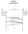
- Fig. 3 is a view depicting a prior art transmission procedure of transmitting/receiving data packets by using a multiplex system.
- Figs. 4A and 4B show an example of a data format to be used for a communication system according to one aspect of the present invention.
- Figs. 5A and 5B show an example of a data format to be used for a communication system according to another aspect of the present invention.
- Figs. 6A, 6B and 6C show an example of a data format to be used for a communication system according to another aspect of the present invention.
- Figs. 7A, 7B and 7C show an example of a data format to be used for a communication system according to another aspect of the present invention.
- Figs. 8A and 8B show a header field of a data packet format to be used for a communication system according to an aspect of the present invention.
- Fig. 9 is a flow chart depicting the operation of a communication system according to one aspect of the present invention.
- Fig. 10 is a flow chart depicting the operation of a communication system according to another aspect of the present invention.
- Fig. 11 is a flow chart depicting the operation of a communication system according to another aspect of the present invention.
- Fig. 12 is a schematic construction view of a multiplex spread-spectrum communication system.
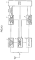
- Fig. 13 is a detailed circuit diagram of a transmitting and receiving device in the system of Fig. 12.
- Figs. 14A and 14B are a waveform diagram of a correlation signal for explaining the operation of a communication system according to the present invention.
- a spread-spectrum communication system has been recently developed and put to the practical use, which advantage is immunity to interference such as multipath interference and color noise as compared with the usual narrow-bandwidth communication.
- the spread-spectrum communication system involves a problem that the high-speed data transmissions need to use a bandwidth widened by a factor of a spread-coefficient of a signal to be transmitted. For example, when data of 1 Mbps is transmitted by using a code having a spread-coefficient of 11, the data transmission rate is 11 Mcps (chips per second). If data of 10 Mbps is transmitted, the chip rate is 110 Mcps. This condition is difficult to realize since a necessary bandwidth is of 110 MHz to 220 MHz and the circuit must operate at an increased rate.
- the present applicant have proposed two methods of increasing a data transmission rate without increasing a chip rate by applying multiplexing spread-spectrum signals.
- One of the methods is a spread-spectrum signal multiplexing system described in Japanese Laid-open Patent Publication (TOKKAI HEI) No. 9-55714 and the other mission system having a multiplex portion and a not-multiplexed portion, which have filed in Japanese Laid-open Patent Publication (TOKKAI HEI) No. 9-298491.
- Fig. 1A shows a data transfer format having a not-multiplexed (simplex) portion and a multiplexed portion while Fig. 1B shows a data transfer format having all multiplexed portions.
- the data transmission format including the simplex portion and the multiplex portion is used for providing the compatibility of the data communication system.
- each station can select a desired multiplexing number for data transmission and, therefore, a receiving station can not receive data without previously knowing the multiplexing number of the transmission.
- each station can transmit all signals in a multiplexed state as shown in Fig. 1B.
- a transmitting station must inform a receiving station of the number of data multiplexed and transmitted thereto.
- a simplex sequence portion of the data transfer format (as shown in Fig. 1A) is written with common information including the multiplex number which will be selected by the receiving station.
- the data communication is usually conducted between a transmitting station and a receiving station when the latter selected the informed multiplex number thus decided at and transmitted from the former.
- Fig. 2 shows an example of this correlation.
- Fig. 2 there are plotted results of experiments with four types of multiplexed data: simplex, double multiplexed with and without correlation improvement and five multiplexed with and without correlation improvement.
- the correlatively improved characteristics were obtained by applying a technique proposed by the present applicant in Japanese Patent Application Serial No. 8-13963.
- a necessary C/N value of 5-multiplex transmission without correlation improvement differs by 15 dB from that of the simplex transmission. There is still a difference of about 7.5 dB between the 5-multiplex transmission with correlation improvement according to the method proposed by the present applicant and the simplex transmission.
- the communication is now conducted between Stations A and B.
- the station A transmits a packet of data to the station B.
- the station B Upon receipt of the data packet the station B transmits an ACK (acknowledge) signal or a NAK (Negative acknowledge) signal to the station A if the received data was correct or incorrect.
- ACK acknowledgenowledge
- NAK Negative acknowledge
- This judgment is usually made by checking such an error detection code as a CRC (Cyclic Redundancy Check) contained in the received data.
- CRC Cyclic Redundancy Check
- the station A On receipt of the ACK signal, the station A transmits a next packet of data to the station B. With the NAK signal received or no response from the station B, the station A re-transmits the same packet once transmitted to the station B.
- a transmission error may occur in a packet containing a long data portion but ACK and NAK signals containing short data may rarely be subject to transmission error.
- a multiplex transmission system previously proposed by the present applicant encountered a problem that an increase of the multiplexing number is associated with a larger increase of the transmission error rate as compared with that in a typical conventional data communication system and even the ACK and NAK signals from the station B may also be lost or incorrectly received.
- the station A With incorrectly received response signal, the station A must re-transmit the packet once transmitted to the station B even if the latter correctly received the same packet. If so, the station A transmits the unnecessary packet instead of a next packet, resulting in lowering total throughput of the communication.
- the format includes a simplex header portion and a multiplexed data portion.
- the header portion is analogous in structure to the header portion of the format of Fig. 1A.
- the station B On receipt of the header portion, the station B synchronizes a spread-spectrum signals, reproduces the clock and accomplishes the automatic gain control (AGC) according to a signal for bit-synchronization and synchronization of the data by synchronization-pattern.
- AGC automatic gain control
- the station B looks for and recognizes information about the multiplexing number and aligns its circuit to the recognized multiplexing number. The station B then knows the length of the packet received, decodes the packet and performs cyclic redundancy checking (CRC) to judge whether data was correctly received or not.
- CRC cyclic redundancy checking
- an upper layer computer of the station B determines which signal ACK or NAK to be sent to the station A.
- the signal ACK or NAK is sent to the station A in the simplex (not multiplexed) format together with a signal indicating the multiplexing number being always 1.
- the station A On receipt of the signal from the station B, the station A similarly synchronizes the spread-spectrum signals and reproduces the clock and accomplishes the automatic gain control (AGC) according to a signal for bit-synchronization and synchronization of the data by synchronization-pattern.
- AGC automatic gain control
- the station A recognizes the multiplexing number by the received information and aligns its circuit to the number recognized.
- the station A then receives the signal ACK or NAK and perform error checking by using a CRC to determine whether data was correctly received or not.
- the signals ACK and NAK transmitted in the simplex state can have a considerably improved error rate as compared with that of the signals transmitted in a multiplexed format. For example, they attain an error rate improved by 7.5 - 15 dB as compared with those transmitted in a 5-multiplexed format.
- the transmission error with signals ACK and NAK can be surely reduced by sending them in the simplex format.
- the simplex transmission of a signal ACK or NAK signal requires a little longer time than the multiplexed data transmission but a total throughput of the transmissions can be considerably improved because it takes much time for re-transmitting an error packet from the station A.
- This data format is used for multiplexing all signals used for transmission, including data to be transmitted, and has a header portion similar to that in a conventional format and is also multiplexed.
- the multiplexing number was previously defined at the time when the communication system has been brought into operation.
- the header has a data structure similar to that of the example shown in Figs. 4A and 4B excepting that it does not need the multiplexing number information because this number has been previously defined and known.
- the receiver is preset to the known multiplexing number.
- the station B On receipt of the header portion, the station B synchronizes a spread spectrum signals and reproduces the clock and accomplishes the automatic gain control (AGC) according to a signal for bit-synchronizing and synchronization of the data by synchronization-pattern.
- AGC automatic gain control
- the station B then knows the length of the packet received, decodes the packet and performs cyclic redundancy checking (CRC) to judge whether data was correctly received or not.
- CRC cyclic redundancy checking
- the upper layer processor of the station B determines which signal ACK or NAK to be sent to the station A.
- the signal ACK or NAK is, sent to the station A in the simplex (not multiplexed) format.
- the station A is ready to receive a simplex (not multiplexed) signal at its receiver since it is a common known rule that a ACK or NAK signal is sent in simplex format from the station B.
- the station A On receipt of the signal from the station B, the station A similarly synchronizes the spread-spectrum signals and reproduces the clock and accomplishes the automatic gain control (AGC) according to a signal for bit-synchronization and synchronization of the data by synchronization-pattern.
- AGC automatic gain control
- the station A then receives the signal ACK or NAK and perform error checking by CRC in the data to determine whether data was correctly received or not.
- the signals ACK and NAK transmitted in the simplex mode can have a considerably improved error rate as compared with that of the signals transmitted in a multiplexed state.
- the transmission error with signals ACK and NAK can be surely reduced by sending them in the simplex format.
- a transmitter-receiver unit must be set into the multiplex mode when transmitting data and it must be set into the simplex mode when receiving an ACK signal or a NAK signal after the transmitting.
- a transmitter-receiver unit must be set into the multiplex mode when standing by for receiving since the data in the format is always multiplexed.
- the simplex transmission of the signal ACK or NAK requires a little longer time than the multiplexed data transmission but a total throughput of the system can be considerably improved because it takes much time for re-transmitting error packet from the station A.
- CSMA/CA Carrier sense multiplex access with call Accepted
- RTS/CTS Request To Send/Clear To Send
- the transmitting station can first transmit data to the receiving station.
- a transmitting station sends to the a receiving station a short signal for recognizing whether the connection with the station is possible or not.
- the transmitting station After receiving an ACK signal from the receiving station, the transmitting station transmits data to the receiving station. This may avoid transmission of full length of data to a party that can not receive it, thus improving the total throughput of the system.
- each signal to be transmitted has a header in a simplex (not multiplexed) state and a RTS (Request to Send)/CTS (Clear to Send) portion in a simplex state.
- the header portion has the data structure similar to that shown in Fig. 1.
- a receiving station B On receipt of the header portion, a receiving station B performs operations for synchronizing the spread-spectrum signals, reproducing a clock, setting AGC according to a signal for bit-synchronization and accomplishing data synchronization by synchronization-pattern.
- the station B recognizes the multiplexing number by the received information and aligns its circuit to the number recognized as 1 (simplex).
- the station B then transmits a response signal in the simplex state (the same as in the first embodiment). This simplex signal is used for acknowledging the connection between the parties is established.
- the station A transmits data in a multiplexed state and then in a simplex state.
- a demodulator synchronizes the spread-spectrum signals and reproduces the clock and then accomplishes the automatic gain control (AGC) according to a signal for bit synchronization and synchronization of the data by synchronization-pattern.
- AGC automatic gain control
- the station B recognizes the multiplexing number by the received information and aligns its circuit to the recognized multiplexing number. The station B then knows the length of the packet received, decodes the packet and performs cyclic redundancy checking (CRC) to judge whether data was correctly received or not.
- CRC cyclic redundancy checking
- the upper layer processor of the station B determines which signal ACK or NAK to be sent to the station A.
- the signal ACK or NAK is sent to the station A in the simplex (not multiplexed) format together with a signal indicating the multiplexing number being always 1.
- the station A On receipt of the signal from the station B, the station A similarly synchronizes the spread-spectrum signals and reproduces the clock and accomplishes the automatic gain control (AGC) according to a signal for bit-synchronization and synchronization of the data by synchronization-pattern.
- AGC automatic gain control
- the station A recognizes the multiplexing number by the received information and aligns its circuit to the number recognized.
- the station A then receives the signal ACK or NAK and perform error checking by using a CRC to determine whether data was correctly received or not.
- the total throughput of the system can be improved by reducing the error rate of the transmissions between stations.
- Transmitting station A transmits first all signals for establishing the connection with a receiving station B in simplex (not multiplexed) state assuring an improved error rate. After the connection was established, the communication between the stations A and B is carried out in the same manner as described for the embodiment 1 (shown in Figs. 5A and 5B).
- the data transmission is conducted in the multiplex mode with the preset and known multiplexing number.
- the header has a data structure similar to that of the example (shown in Figs. 6A, 6B and 6C) excepting that it does not need the multiplexing number information because this number has been previously determined and known at the time when the system was brought into operation.
- the receiver is preset to the known multiplexing number.
- the station B On receipt of the header information, the station B synchronizes a spread spectrum signals, reproduces the clock and accomplishes the automatic gain control (AGC) according to a signal for bit-synchronization and synchronization of the data by synchronization-pattern.
- AGC automatic gain control
- the station B then knows the length of the packet received, decodes the packet and performs cyclic redundancy checking (CRC) to judge whether data was correctly received or not.
- CRC cyclic redundancy checking
- the upper layer processor of the station B determines which signal ACK or NAK to be sent to the station A.
- the signal ACK or NAK is sent to the station A in the simplex (not multiplexed) format.
- the station A is ready to receive a simplex (not multiplexed) signal at its receiver since it is a known common rule that a ACK or NAK signal is sent in simplex format from the station B.
- the station A On receipt of the signal from the station B, the station A similarly synchronizes the spread-spectrum signals and reproduces the clock signal and accomplishes the automatic gain control (AGC) according to a signal for bit-synchronization and synchronization of the data by synchronization-pattern.
- AGC automatic gain control
- the station A then receives the signal ACK or NAK and perform error checking by a CRC in the data to determine whether data was correctly received or not.
- transmitter-receiver unit at both stations A and B are first set into simplex mode when establishing the connection between them and then into the multiplex mode when transmitting and receiving multiplexed data. After this, they are set again into the simplex mode for receiving and transmitting an ACK signal or a NAK signal.
- the simplex-mode transmission of the signal ACK or NAK requires a little longer time than the multiplex transmission but a total throughput of the system can be considerably improved because it takes much time for re-transmitting error packet from the station A.
- a third embodiment of the present invention is described as follows:
- the header portion is analogous to one of the prior art (Fig. 8A) and the response signals (e.g., the ACK signal and so on) are arranged in the data portion.
- a flag for registerring an involved response-signals is set in a portion of various information.
- the header portion of the present embodiment differs from the prior art example shown in Fig. 8A by the absence of information about the multiplexing number, which is unnecessary since the header portion is always transferred in the simplex mode. Accordingly, a response signal or connecting signal is arranged in the header portion shown in Fig. 8B, which corresponds to the header portion of Fig. 8A in which the multiplexing number and packet length are arranged.
- the system sets a maximal number of multiplexed data (at Step 9-1).
- a maximal value is set in a simplex portion of the format and the maximum number of multiplexed data (multiplexing number) is set the data portion thereof.
- Step 9-2 Data is transmitted (Step 9-2) and a ACK or NAK of response signal is received (Step 9-2), then, content of the response signal is checked (Step 9-4).
- Step 9-4 content of the response signal is checked
- a subsequent packet data is detected (Step 9-5) and transmitted if such detected.
- the data transmission ends when the last requested data was transmitted (Step 9-6).
- Step 9-4 In the event if a NAK signal or no response is received or any response signal is incorrectly received (at Step 9-4), it is considered that the data could not correctly be received by the receiving party. In this instance, the same packet is transmitted again. Every time when the such event (failure) occurred, the number "n" of the failures (NAK signal, no response and incorrectly received response) is compared with a preset number "k" (Step 9-7) and re-transmission of the same packet is repeated until the number n reaches the preset value k (Step 9-8).
- the error rate can be reduced by reducing the number of multiplexed data.
- the occurrence of transmission failures can therefore be reduced.
- the procedure is flexibly applied to transmit at a high transfer rate while the transmission is well conditioned and to transmit data in less multiplexed state at a low transfer rate (at a low error rate). This improves a total throughput of the system.
- the presettable value "k" shall be determined, based on the results of simulations and experiments, to an optimal value at which a maximal throughput of the system may be obtained.
- the diversity switching technique is preferably used owing to its simple circuitry and effectiveness.
- a current working antenna is often changed to another when, not in middle of transmission, an ACK signal could not be received from a receiving party after transmission of a packet thereto and then the same packet through the switched-ON antenna is re-transmitted. Namely, the switching of a working antenna from one to another may be conducted every packet-transmission.
- the system sets a possible maximum number of multiplexed data (at Step 10-1).
- Step 10-2 Data is transmitted (Step 10-2) and a ACK or NAK signal is received (Step 10-3) and checked (Step 10-4). With the ACK signal received for acknowledging the correct transmission, a subsequent packet data is detected (Step 10-5) and transmitted if the data exists. The data transmission ends when the last requested data was transmitted (Step 10-6).
- Step 10-4 In the event if a NAK signal or no response is received or any response signal is incorrectly received (at Step 10-4), it is considered that the data could not correctly be received by the receiving party. In this instance, the same packet is transmitted again. Every time when the such event (failure) occurred, the number "n" of the failures (NAK signal, no response and incorrectly received response) is compared with two different preset values "j" and "k" (Step 10-7, Step 10-8) and re-transmission of the same packet is repeated until the number "n” reaches the preset value k (Step 10-9).
- the use of the aerial diversity switching method in combination with the method of changing the number of multiplexed data can further improve the throughput of the system.
- the transmission rate is decreased with a reduced number of multiplexed data but is not decreased by switching the aerial diversity. Accordingly, it is expected to realize the successful transmission by using the procedure that can provide the effect of the improved aerial diversity first and the effect of the reduced number of multiplexed data, if the problem could not be eliminated by improving the aerial diversity.
- the presettable value "k" shall be determined, based on the results of simulations and experiments, to an optimal value at which a maximal throughput of the system may be obtained.
- the number of multiplexed data is first set at the maximal value and it is then reduced as the need be.
- the propagation conditions may get better or worse during transmissions. Accordingly, it is desirable to reduce the transmission rate while the propagating conditions are wrong but to increase the number of multiplexed data when the propagation conditions are improved. This may improve the throughput of the system.
- the present embodiment includes in its system competitive type counters that operate as described in the flow chart of Fig. 11.
- the system sets the number of multiplexed data (Step 11-1).
- the maximal value for example, is set.
- Step 11-2 Data is transmitted (Step 11-2) and a ACK or NAK signal is received (Step 11-3) and checked (Step 11-4).
- a subsequent packet data is detected (Step 11-6) and transmitted if data is found.
- the data transmission ends when the last requested data was transmitted (Step 11-7).
- Step 11-4 In the event if a NAK signal or no response is received or any response signal is incorrectly received (at Step 11-4), it is considered that the data could not correctly be received by the receiving party. In this instance, the same packet is transmitted again (Step 11-8).
- the competitive counters count the number of received ACK signals and the number of received NAK signals (including no response and incorrectly received signals) respectively (Step 11-5).
- the number of multiplexed data is controlled to obtain a constant ACK-to-NAK ratio.
- This ratio shall be determined to be optimal based on the results of simulations and experiments and the circumstances.
- the ACK-to-NAK ratio is set for example at 1:3.
- the packets are transmitted first at the maximal number of multiplexed data while the number of ACK signals is predominant.
- the number of NAK signals increases and exceeds the preset ratio of 1:3, the number of multiplexed data is reduced to decrease the error rate of transmissions (Step 11-1).
- the number of multiplexed data is controlled by increasing the set value (Step 11-1).
- the seventh embodiment of the present invention is described as follows:
- This embodiment is featured in that the priority is given to the aerial switching method over the method of decreasing the multiplexing number in case of reducing the multiplexing number whereas the priority is given to the method of increasing the multiplexing number in the case of increasing the number of multiplexed data.
- the multiplexing number is first increased when the ratio of ACK signals is increased whilst the current antenna is first changed-over to another when the ratio of NAK signals increased.
- the system can be controlled to transmit packets at a higher transmission rate.
- communication devices composing the spread spectrum (SS) multiplex communication system carry out two-way communication under the control of the upper-layer.
- communicating stations A' and B' may alternately transmit and receive data to and from each other under the control of the upper-layer.
- the station B' transmits to the station A' same multiplexing number at which the station A' transmitted a last packet to the station B'.
- Fig. 13 is a detailed circuit diagram of a communication device of the system, which circuit includes a receiver-side demodulator 1, a receiver-side data-processor 4, a transmitter-side modulator 3, a transmitter-side data-processor 5, an upper-layer 6 and a multiplexing number controller 2.
- the communication device provided with the above-mentioned circuit has an integral transmitter-receiver and controlled by the upper-layer 6.
- the upper layer 6 controls demodulated and processed resultants in the receiver-side and operates the multiplexing number controller 2 to determine the number of multiplexed data and transmit the data multiplexed at the determined number in the transmitter-side.
- the stations A' and B' may alternately transmit the optimally multiplexed data respectively, thus improving the throughput of the system.
- a ninth embodiment of the present invention is described as follows:
- Figs. 14A and 14B show correlation waveforms of multiplexed data.
- a distance between correlation spikes is lager for a simplex (not multiplexed) data and becomes shorter as the number of multiplexed data increases.
- states of spikes in the presence of a delay dispersion are shown part (a) and part (b) in Fig. 14B.
- Part (a) in Fig. 14B relates to the case of a small delay dispersion and Part (b) in Fig. 14B relates to the case of a large delay dispersion.
- Transmission of largely multiplexed data under the circumstance with a large delay dispersion (part (b)) may cause the correlation spikes to overlap one another, resulting in impairing the data.
- response signals ASK and NAK are featured by simplex (not multiplexed). Accordingly, the delay dispersion is determined from the state of the response signal and a suitable number of data to be multiplexed is then determined.
- the delay dispersion may be of several chips and can not be so large that two subsequent spikes of a not-multiplexed signal may overlap each other. Utilizing this feature of a simplex signal, a delay dispersion of the simplex signal is determined by the correlation waveforms and the suitable number of data to be multiplexed is then determined.
- the multiplexing number is thus effectively determined whilst the embodiments 4 to 8 change the multiplexing number only based on the error data with no consideration of a delay dispersion value.
- a tenth embodiment of the present invention is as follows:
- the ninth embodiment provides the method of effectively transmit data adaptively multiplexed by determining the number of data to be multiplexed on the basis of the delay dispersion value. For this purpose, it is necessary to determine the delay dispersion value.
- the delay dispersion value can be determined by using hardware means as well as software means. However, this is necessarily associated with the increased circuitry and an increased amount of the working program.
- the base station performs the above-mentioned calculation and other terminal stations determine the multiplexing number from the data determined at the base station.
- the base station may inform each terminal of the delay dispersion value by inserting it in the data transmitted thereto or each terminal station uses the same number of multiplexed data in a packet lastly received from the base station.
- An eleventh embodiment of the present invention is as follows:
- the tenth embodiment provides that the delay dispersion value is determined at the base station.
- the sixth and seventh embodiments determine the number of data to be multiplexed at each station. However, one-to-multiple or multiple-to-multiple communication may be associated with frequent change of communicating parties.
- each station stores the delay dispersion value and the adaptive multiplexing number determined in advance for each party with an ID.
- This solution enables each station to rapidly select the suitable number of data to be multiplexed and transmitted to any party.
- the throughput of the system can be thus improved.
Abstract
Description
With a system having not predetermined multiplexing number, a transmitting station must inform a receiving station of the number of data multiplexed and transmitted thereto.
Claims (11)
- A direct-spread-spectrum communication system for transmitting and receiving signals spread by using spread-code and multiplexed according to a data format having a simplex portion plus a multiplexed portion or only a multiplexed portion or only a simplex portion by using multiplexing means for multiplexing signals at a delay time of any desired number of chip of the spread-code, the spread signals to be transmitted and received being packetized and transmitted by an ARQ (Automatic Repeat Request) method, wherein an ACK (Acknowledge) signal and a NAK (Negative Acknowledge) signal for acknowledging the receipt of correctly or incorrectly transmitted signals are transmitted and received as simplex spread-spectrum signals.
- A direct-spread-spectrum communication system as defined in claim 1, characterized in that a procedure for recognizing the connection between terminals by a CSMA/CA (Carrier Sense Multiple Access with call Accepted) with RTS/CTS (Request To Send/Clear To Send) method is executed, before transmitting and receiving data portion according to the data format, by using a packet to be transmitted and received as simplex spread-spectrum signals.
- A direct-spread-spectrum communication system as defined in claim 1 or claim 2, characterized in that a response data format for ARQ system includes a flag for identifying response signals and response data such as ACK signal arranged in fields of the response data format where the number of multiplexed data and a packet length were previously arranged.
- A direct-spread-spectrum communication system as defined in any one of claims 1 to 3, characterized in that the number of multiplexed data in the multiplexing means data is controlled and can be decreased by the control when a result of counts of received NAK signals indicating incorrect receipt of transmissions including no response or incorrectly received response reaches a specified preset value and then data in a less multiplexed state is re-transmitted and received.
- A direct-spread-spectrum communication system as defined in any one of claims 1 to 4, characterized in that the system is further provided with an aerial diversity system by which a working aerial diversity is changed when a result of counts of received NAK signals indicating incorrect receipt of transmissions including no response or incorrectly received response reaches a specified preset value, and data is then re-transmitted therethrough and received.
- A direct-spread-spectrum communication system for transmitting and receiving signals spread by using spread-code and multiplexed according to a data format having a simplex portion plus a multiplexed portion by using multiplexing means for multiplexing signals at a delay time of any desired number of chip of the spread-code, the spread signals to be transmitted and received being packetized and transmitted by an ARQ (Automatic Repeat Requesting) method, wherein the number of data to be multiplexed in the multiplexing means is controlled, a frequency of ACK (Acknowledge) signals for acknowledging the receipt of correctly transmitted signals and a frequency of NAK (Negative Acknowledge) signals for acknowledging the receipt of incorrectly transmitted signals including no response or incorrectly received response are countable respectively and the number of data to be multiplexed, transmitted and received is controlled according to the ACK to NAK ratio determined from the respective count values.
- A direct-spread-spectrum communication system as defined in any one of claims 1 to 6, characterized in that the system is further provided with the aerial diversity system to change a working aerial diversity according to a ratio of counts of received ACK signals to counts of received NAK signals indicating incorrect receipt of transmission including no response or incorrectly received response and transmit data at the selected aerial diversity.
- A direct-spread-spectrum communication system as defined in any one of claims 4 to 7, characterized in that the number of data to be multiplexed, which has been received, is used as an initial value to be set at the multiplexing means when a direction of data communication between stations is reversed.
- A direct spread-spectrum communication system as defined in any one of claims 1 to 8, characterized in that the number of data to be multiplexed in the multiplexing means is controlled, a delay dispersion of the ACK or NAK signal transmitted and received in a simplex state is calculated and an optimal value of the number of data to be multiplexed for transmission is determined according to the calculation result of the delay dispersion and set at the multiplexing means.
- A direct-spread-spectrum communication system as defined in claim 9, characterized in that the system is composed of a base station and a terminal station, only the base station calculates the delay dispersion of the simplex signal and determines the number of data to be multiplexed for transmission according to the calculation result and the terminal station uses the number of data to be multiplexed, which is determined by the base station.
- A direct-spread-spectrum communication system as defined in any one of claims 1 to 10, characterized in that the system is a one-to-multiple or multiple-to multiple communication system in which each of stations composing the system can control the number of data to be multiplexed for transmission in the multiplexing means and stores the numbers of data to be multiplexed for transmission, which are previously determined for respective connectable stations together with respective identifications, and sets at the multiplexing means the number of data to be multiplexed for transmission.
Applications Claiming Priority (3)
| Application Number | Priority Date | Filing Date | Title |
|---|---|---|---|
| JP3153997A JP3242856B2 (en) | 1997-02-17 | 1997-02-17 | Direct spread spectrum communication system |
| JP3153997 | 1997-02-17 | ||
| JP31539/97 | 1997-02-17 |
Publications (2)
| Publication Number | Publication Date |
|---|---|
| EP0859475A2 true EP0859475A2 (en) | 1998-08-19 |
| EP0859475A3 EP0859475A3 (en) | 2003-02-26 |
Family
ID=12334004
Family Applications (1)
| Application Number | Title | Priority Date | Filing Date |
|---|---|---|---|
| EP19980100913 Withdrawn EP0859475A3 (en) | 1997-02-17 | 1998-01-20 | Direct sequence spread spectrum communication system |
Country Status (3)
| Country | Link |
|---|---|
| US (1) | US6266360B1 (en) |
| EP (1) | EP0859475A3 (en) |
| JP (1) | JP3242856B2 (en) |
Cited By (7)
| Publication number | Priority date | Publication date | Assignee | Title |
|---|---|---|---|---|
| WO2002043293A1 (en) * | 2000-11-27 | 2002-05-30 | Matsushita Electric Industrial Co., Ltd. | Ofdm communication apparatus and ofdm communication method |
| EP1419603A1 (en) * | 2001-08-24 | 2004-05-19 | Interdigital Technology Corporation | Method for physical layer automatic repeat request for a base station |
| EP1421743A2 (en) * | 2001-08-24 | 2004-05-26 | Interdigital Technology Corporation | Implementing a physical layer automatic repeat request for a subscriber unit |
| EP1421709A1 (en) * | 2001-08-24 | 2004-05-26 | Interdigital Technology Corporation | Method for physical layer automatic repeat request for a subscriber unit |
| EP1436915A1 (en) * | 2001-08-24 | 2004-07-14 | Interdigital Technology Corporation | Physical layer automatic repeat request (arq) |
| EP1436701A1 (en) * | 2001-08-24 | 2004-07-14 | Interdigital Technology Corporation | Base station implementing a physical layer automatic repeat request |
| EP1492263A1 (en) * | 2003-06-27 | 2004-12-29 | Kabushiki Kaisha Toshiba | Radio communication apparatus and communication mode control method of a mobile communication system |
Families Citing this family (21)
| Publication number | Priority date | Publication date | Assignee | Title |
|---|---|---|---|---|
| JP2000078117A (en) * | 1998-09-01 | 2000-03-14 | Toyota Autom Loom Works Ltd | Radio communication method and radio communication system |
| JP3019092B1 (en) * | 1998-12-07 | 2000-03-13 | 日本電気株式会社 | Wireless random access control method and apparatus |
| FI113822B (en) * | 1999-01-19 | 2004-06-15 | Nokia Corp | Controlled recovery for data network errors |
| FI111888B (en) * | 2000-02-25 | 2003-09-30 | Nokia Corp | An adaptive method and system for implementing gradual redundancy at the reception |
| CN100467491C (en) * | 2001-01-17 | 2009-03-11 | 生物质转化有限责任公司 | Disruption of plant material to readily hydrolyzable cellulosic particles |
| TW576061B (en) * | 2001-08-13 | 2004-02-11 | Via Tech Inc | Device and method for load balancing of packet switching |
| JP2009284494A (en) * | 2001-11-13 | 2009-12-03 | Panasonic Corp | Transmission method, transmission apparatus, and reception apparatus |
| JP4606407B2 (en) * | 2001-11-13 | 2011-01-05 | パナソニック株式会社 | Transmission method and transmission apparatus |
| JP3997890B2 (en) | 2001-11-13 | 2007-10-24 | 松下電器産業株式会社 | Transmission method and transmission apparatus |
| US7009957B2 (en) * | 2002-02-28 | 2006-03-07 | Airmagnet, Inc. | Measuring the throughput of transmissions over wireless local area networks |
| CN100411328C (en) * | 2002-06-25 | 2008-08-13 | 三菱电机株式会社 | Wireless base station apparatus |
| JP4142917B2 (en) * | 2002-08-23 | 2008-09-03 | 松下電器産業株式会社 | CDMA transmitter and OFDM-CDMA transmitter |
| AU2002368322A1 (en) * | 2002-11-05 | 2004-06-07 | Nokia Corporation | Method, device and system for determining a transmission power for arq related re-transmissions |
| JP4126058B2 (en) | 2003-06-18 | 2008-07-30 | 日本電信電話株式会社 | Wireless packet communication method and wireless packet communication device |
| US7864903B2 (en) | 2003-11-21 | 2011-01-04 | Panasonic Corporation | Multi-antenna reception apparatus, multi-antenna reception method, multi-antenna transmission apparatus and multi-antenna communication system |
| JP4510870B2 (en) * | 2003-11-21 | 2010-07-28 | パナソニック株式会社 | Wireless communication method and wireless communication device |
| JP2004166288A (en) * | 2003-12-01 | 2004-06-10 | Sharp Corp | Radio communication device |
| US7957351B2 (en) * | 2005-04-04 | 2011-06-07 | Qualcomm Incorporated | Method and apparatus for management of multi-carrier communications in a wireless communication system |
| RU2433541C2 (en) | 2007-07-16 | 2011-11-10 | Самсунг Электроникс Ко., Лтд. | Apparatus and method for transmitting channel quality indicator and acknowledgement signals in sc-fdma communication systems |
| GB2487044A (en) * | 2010-12-24 | 2012-07-11 | Enmodus Ltd | Determining whether a signal is present by comparing phase measurements, and distinguishing between signals |
| JP5794302B2 (en) * | 2011-07-27 | 2015-10-14 | 富士通株式会社 | Wireless communication system and wireless communication apparatus |
Citations (4)
| Publication number | Priority date | Publication date | Assignee | Title |
|---|---|---|---|---|
| US5440545A (en) * | 1993-08-02 | 1995-08-08 | Motorola, Inc. | Packet delivery system |
| US5537414A (en) * | 1992-07-07 | 1996-07-16 | Hitachi, Ltd. | Method of wireless communication between base station and mobile station and multiple access communication system |
| EP0735701A2 (en) * | 1995-03-31 | 1996-10-02 | AT&T IPM Corp. | Switched antenna diversity transmission method and system using ARQ techniques |
| WO1996041493A1 (en) * | 1995-06-07 | 1996-12-19 | Telefonaktiebolaget Lm Ericsson (Publ) | Digital control channels having logical channels supporting broadcast sms |
Family Cites Families (6)
| Publication number | Priority date | Publication date | Assignee | Title |
|---|---|---|---|---|
| JP2700843B2 (en) * | 1991-12-10 | 1998-01-21 | 三菱電機株式会社 | Multiplex communication controller |
| JP3151119B2 (en) * | 1995-03-27 | 2001-04-03 | シャープ株式会社 | Parallel spread spectrum communication system |
| JPH0955714A (en) * | 1995-08-11 | 1997-02-25 | Sharp Corp | Spread spectrum communication system |
| JP3244434B2 (en) * | 1996-01-30 | 2002-01-07 | シャープ株式会社 | Spread spectrum communication reception method |
| JP3337613B2 (en) * | 1996-03-05 | 2002-10-21 | シャープ株式会社 | Spread spectrum communication system |
| US5983382A (en) * | 1996-12-31 | 1999-11-09 | Lucent Technologies, Inc. | Automatic retransmission query (ARQ) with inner code for generating multiple provisional decodings of a data packet |
-
1997
- 1997-02-17 JP JP3153997A patent/JP3242856B2/en not_active Expired - Fee Related
-
1998
- 1998-01-20 EP EP19980100913 patent/EP0859475A3/en not_active Withdrawn
- 1998-01-22 US US09/010,977 patent/US6266360B1/en not_active Expired - Fee Related
Patent Citations (4)
| Publication number | Priority date | Publication date | Assignee | Title |
|---|---|---|---|---|
| US5537414A (en) * | 1992-07-07 | 1996-07-16 | Hitachi, Ltd. | Method of wireless communication between base station and mobile station and multiple access communication system |
| US5440545A (en) * | 1993-08-02 | 1995-08-08 | Motorola, Inc. | Packet delivery system |
| EP0735701A2 (en) * | 1995-03-31 | 1996-10-02 | AT&T IPM Corp. | Switched antenna diversity transmission method and system using ARQ techniques |
| WO1996041493A1 (en) * | 1995-06-07 | 1996-12-19 | Telefonaktiebolaget Lm Ericsson (Publ) | Digital control channels having logical channels supporting broadcast sms |
Non-Patent Citations (1)
| Title |
|---|
| LEE I-W ET AL: "A STUDY ON THE PERFORMANCE IMPROVEMENTS OF ERROR CONTROL SCHEMES INDIGITAL CELLULAR DS/CDMA SYSTEMS" IEICE TRANSACTIONS ON COMMUNICATIONS, INSTITUTE OF ELECTRONICS INFORMATION AND COMM. ENG. TOKYO, JP, vol. E77-B, no. 7, 1 July 1994 (1994-07-01), pages 883-890, XP000471318 ISSN: 0916-8516 * |
Cited By (19)
| Publication number | Priority date | Publication date | Assignee | Title |
|---|---|---|---|---|
| WO2002043293A1 (en) * | 2000-11-27 | 2002-05-30 | Matsushita Electric Industrial Co., Ltd. | Ofdm communication apparatus and ofdm communication method |
| EP1421743A4 (en) * | 2001-08-24 | 2006-12-06 | Interdigital Tech Corp | Implementing a physical layer automatic repeat request for a subscriber unit |
| EP2017995A3 (en) * | 2001-08-24 | 2010-05-05 | Interdigital Technology Corporation | Physical layer automatic repeat request (ARQ) |
| EP1419603A4 (en) * | 2001-08-24 | 2006-12-06 | Interdigital Tech Corp | Method for physical layer automatic repeat request for a base station |
| EP1436915A4 (en) * | 2001-08-24 | 2006-12-06 | Interdigital Tech Corp | Physical layer automatic repeat request (arq) |
| EP1436701A1 (en) * | 2001-08-24 | 2004-07-14 | Interdigital Technology Corporation | Base station implementing a physical layer automatic repeat request |
| EP1436701A4 (en) * | 2001-08-24 | 2006-12-06 | Interdigital Tech Corp | Base station implementing a physical layer automatic repeat request |
| EP1421709A4 (en) * | 2001-08-24 | 2006-12-06 | Interdigital Tech Corp | Method for physical layer automatic repeat request for a subscriber unit |
| EP1419603A1 (en) * | 2001-08-24 | 2004-05-19 | Interdigital Technology Corporation | Method for physical layer automatic repeat request for a base station |
| EP2793409A1 (en) * | 2001-08-24 | 2014-10-22 | Interdigital Technology Corporation | Implementing a physical layer automatic repeat request for a subscriber unit |
| EP1421709A1 (en) * | 2001-08-24 | 2004-05-26 | Interdigital Technology Corporation | Method for physical layer automatic repeat request for a subscriber unit |
| EP1436915A1 (en) * | 2001-08-24 | 2004-07-14 | Interdigital Technology Corporation | Physical layer automatic repeat request (arq) |
| US7519018B2 (en) | 2001-08-24 | 2009-04-14 | Interdigital Technology Corporation | Method for physical layer automatic repeat request for a subscriber unit |
| US7672265B2 (en) | 2001-08-24 | 2010-03-02 | Interdigital Technology Corporation | Method for physical layer automatic repeat request for a base station |
| EP1421743A2 (en) * | 2001-08-24 | 2004-05-26 | Interdigital Technology Corporation | Implementing a physical layer automatic repeat request for a subscriber unit |
| EP2214330A2 (en) * | 2001-08-24 | 2010-08-04 | Interdigital Technology Corporation | Implementing a physical layer automatic repeat request for a subscriber unit |
| EP2214330A3 (en) * | 2001-08-24 | 2011-11-16 | Interdigital Technology Corporation | Implementing a physical layer automatic repeat request for a subscriber unit |
| US8102801B2 (en) | 2001-08-24 | 2012-01-24 | Interdigital Technology Corporation | User equipment for physical layer automatic repeat request |
| EP1492263A1 (en) * | 2003-06-27 | 2004-12-29 | Kabushiki Kaisha Toshiba | Radio communication apparatus and communication mode control method of a mobile communication system |
Also Published As
| Publication number | Publication date |
|---|---|
| EP0859475A3 (en) | 2003-02-26 |
| JP3242856B2 (en) | 2001-12-25 |
| US6266360B1 (en) | 2001-07-24 |
| JPH10229383A (en) | 1998-08-25 |
Similar Documents
| Publication | Publication Date | Title |
|---|---|---|
| US6266360B1 (en) | Direct-spread-spectrum communication system | |
| US6581176B1 (en) | Method for transmitting control frames and user data frames in mobile radio communication system | |
| US6574668B1 (en) | Retransmission scheme in wireless computer networks | |
| US8072981B2 (en) | High rate packet data transmission system | |
| US8792400B2 (en) | Wireless communication apparatus, a method of wireless communication, and a program for wireless communication | |
| US6601207B1 (en) | Method and a device for re-transmitting data transfer packets | |
| USRE42744E1 (en) | Method of sending feedback information in a fast automatic repeat request forming part of an overall wireless communication system | |
| US6956855B1 (en) | Apparatus and method for retransmitting data according to radio link protocol in mobile communication system | |
| KR101007524B1 (en) | Method and apparatus for augmenting physical layer arq in a wireless data communication system | |
| US6519731B1 (en) | Assuring sequence number availability in an adaptive hybrid-ARQ coding system | |
| US20010009555A1 (en) | Method and device for robust fallback in data communication systems | |
| EP2056614A1 (en) | Base station and mobile station | |
| CA2621770C (en) | Method and system for data transmission unit retransmission, data receiver and data transmitter | |
| WO2003096298A1 (en) | Method and apparatus for reducing transmission errors in a third generation cellular system | |
| CN101651529A (en) | Method, device and system for data retransmission | |
| EP1436935A2 (en) | Method of transmitting data packets | |
| GB2347585A (en) | Method of allocating wireless resource for transmitting data | |
| KR20040038327A (en) | Antenna assignment method in a radio communication system | |
| CN100527726C (en) | Data communication method | |
| US20040170192A1 (en) | Method of transmitting data packets | |
| AU5292699A (en) | Packet-switched data transmission in radio system | |
| US9215042B2 (en) | Apparatus and method for transmitting and receiving packet data in a wireless communication system using hybrid automatic repeat request | |
| EP1576837B1 (en) | Apparatus and method for use in effecting automatic repeat requests in wireless multiple access communications systems | |
| KR20090075081A (en) | Methods of transmitting and receiving data in communication systems |
Legal Events
| Date | Code | Title | Description |
|---|---|---|---|
| PUAI | Public reference made under article 153(3) epc to a published international application that has entered the european phase |
Free format text: ORIGINAL CODE: 0009012 |
|
| AK | Designated contracting states |
Kind code of ref document: A2 Designated state(s): AT BE CH DE DK ES FI FR GB GR IE IT LI LU MC NL PT SE |
|
| AX | Request for extension of the european patent |
Free format text: AL;LT;LV;MK;RO;SI |
|
| PUAL | Search report despatched |
Free format text: ORIGINAL CODE: 0009013 |
|
| AK | Designated contracting states |
Kind code of ref document: A3 Designated state(s): AT BE CH DE DK ES FI FR GB GR IE IT LI LU MC NL PT SE Designated state(s): AT BE CH DE DK ES FI FR GB GR IE IT LI LU MC NL PT SE |
|
| AX | Request for extension of the european patent |
Extension state: AL LT LV MK RO SI |
|
| AKX | Designation fees paid | ||
| REG | Reference to a national code |
Ref country code: DE Ref legal event code: 8566 |
|
| STAA | Information on the status of an ep patent application or granted ep patent |
Free format text: STATUS: THE APPLICATION IS DEEMED TO BE WITHDRAWN |
|
| 18D | Application deemed to be withdrawn |
Effective date: 20030827 |