EP0859489A2 - Remote monitoring system - Google Patents
Remote monitoring system Download PDFInfo
- Publication number
- EP0859489A2 EP0859489A2 EP98100707A EP98100707A EP0859489A2 EP 0859489 A2 EP0859489 A2 EP 0859489A2 EP 98100707 A EP98100707 A EP 98100707A EP 98100707 A EP98100707 A EP 98100707A EP 0859489 A2 EP0859489 A2 EP 0859489A2
- Authority
- EP
- European Patent Office
- Prior art keywords
- multifunction peripheral
- host
- status information
- remote monitoring
- storage device
- Prior art date
- Legal status (The legal status is an assumption and is not a legal conclusion. Google has not performed a legal analysis and makes no representation as to the accuracy of the status listed.)
- Granted
Links
Images


Classifications
-
- H—ELECTRICITY
- H04—ELECTRIC COMMUNICATION TECHNIQUE
- H04N—PICTORIAL COMMUNICATION, e.g. TELEVISION
- H04N1/00—Scanning, transmission or reproduction of documents or the like, e.g. facsimile transmission; Details thereof
- H04N1/00002—Diagnosis, testing or measuring; Detecting, analysing or monitoring not otherwise provided for
- H04N1/00007—Diagnosis, testing or measuring; Detecting, analysing or monitoring not otherwise provided for relating to particular apparatus or devices
- H04N1/00013—Reading apparatus
-
- G—PHYSICS
- G06—COMPUTING; CALCULATING OR COUNTING
- G06F—ELECTRIC DIGITAL DATA PROCESSING
- G06F3/00—Input arrangements for transferring data to be processed into a form capable of being handled by the computer; Output arrangements for transferring data from processing unit to output unit, e.g. interface arrangements
- G06F3/12—Digital output to print unit, e.g. line printer, chain printer
- G06F3/1201—Dedicated interfaces to print systems
- G06F3/1202—Dedicated interfaces to print systems specifically adapted to achieve a particular effect
- G06F3/121—Facilitating exception or error detection and recovery, e.g. fault, media or consumables depleted
-
- G—PHYSICS
- G06—COMPUTING; CALCULATING OR COUNTING
- G06F—ELECTRIC DIGITAL DATA PROCESSING
- G06F3/00—Input arrangements for transferring data to be processed into a form capable of being handled by the computer; Output arrangements for transferring data from processing unit to output unit, e.g. interface arrangements
- G06F3/12—Digital output to print unit, e.g. line printer, chain printer
- G06F3/1201—Dedicated interfaces to print systems
- G06F3/1223—Dedicated interfaces to print systems specifically adapted to use a particular technique
- G06F3/1229—Printer resources management or printer maintenance, e.g. device status, power levels
-
- G—PHYSICS
- G06—COMPUTING; CALCULATING OR COUNTING
- G06F—ELECTRIC DIGITAL DATA PROCESSING
- G06F3/00—Input arrangements for transferring data to be processed into a form capable of being handled by the computer; Output arrangements for transferring data from processing unit to output unit, e.g. interface arrangements
- G06F3/12—Digital output to print unit, e.g. line printer, chain printer
- G06F3/1201—Dedicated interfaces to print systems
- G06F3/1278—Dedicated interfaces to print systems specifically adapted to adopt a particular infrastructure
- G06F3/1285—Remote printer device, e.g. being remote from client or server
-
- H—ELECTRICITY
- H04—ELECTRIC COMMUNICATION TECHNIQUE
- H04N—PICTORIAL COMMUNICATION, e.g. TELEVISION
- H04N1/00—Scanning, transmission or reproduction of documents or the like, e.g. facsimile transmission; Details thereof
- H04N1/00002—Diagnosis, testing or measuring; Detecting, analysing or monitoring not otherwise provided for
- H04N1/00007—Diagnosis, testing or measuring; Detecting, analysing or monitoring not otherwise provided for relating to particular apparatus or devices
- H04N1/00015—Reproducing apparatus
-
- H—ELECTRICITY
- H04—ELECTRIC COMMUNICATION TECHNIQUE
- H04N—PICTORIAL COMMUNICATION, e.g. TELEVISION
- H04N1/00—Scanning, transmission or reproduction of documents or the like, e.g. facsimile transmission; Details thereof
- H04N1/00002—Diagnosis, testing or measuring; Detecting, analysing or monitoring not otherwise provided for
- H04N1/00026—Methods therefor
- H04N1/00042—Monitoring, i.e. observation
-
- H—ELECTRICITY
- H04—ELECTRIC COMMUNICATION TECHNIQUE
- H04N—PICTORIAL COMMUNICATION, e.g. TELEVISION
- H04N1/00—Scanning, transmission or reproduction of documents or the like, e.g. facsimile transmission; Details thereof
- H04N1/00002—Diagnosis, testing or measuring; Detecting, analysing or monitoring not otherwise provided for
- H04N1/00026—Methods therefor
- H04N1/0005—Methods therefor in service, i.e. during normal operation
-
- H—ELECTRICITY
- H04—ELECTRIC COMMUNICATION TECHNIQUE
- H04N—PICTORIAL COMMUNICATION, e.g. TELEVISION
- H04N1/00—Scanning, transmission or reproduction of documents or the like, e.g. facsimile transmission; Details thereof
- H04N1/00002—Diagnosis, testing or measuring; Detecting, analysing or monitoring not otherwise provided for
- H04N1/00071—Diagnosis, testing or measuring; Detecting, analysing or monitoring not otherwise provided for characterised by the action taken
- H04N1/00074—Indicating or reporting
- H04N1/00079—Indicating or reporting remotely
-
- H—ELECTRICITY
- H04—ELECTRIC COMMUNICATION TECHNIQUE
- H04N—PICTORIAL COMMUNICATION, e.g. TELEVISION
- H04N1/00—Scanning, transmission or reproduction of documents or the like, e.g. facsimile transmission; Details thereof
- H04N1/00002—Diagnosis, testing or measuring; Detecting, analysing or monitoring not otherwise provided for
- H04N1/00071—Diagnosis, testing or measuring; Detecting, analysing or monitoring not otherwise provided for characterised by the action taken
- H04N1/0009—Storage
-
- H—ELECTRICITY
- H04—ELECTRIC COMMUNICATION TECHNIQUE
- H04N—PICTORIAL COMMUNICATION, e.g. TELEVISION
- H04N1/00—Scanning, transmission or reproduction of documents or the like, e.g. facsimile transmission; Details thereof
- H04N1/32—Circuits or arrangements for control or supervision between transmitter and receiver or between image input and image output device, e.g. between a still-image camera and its memory or between a still-image camera and a printer device
- H04N1/32561—Circuits or arrangements for control or supervision between transmitter and receiver or between image input and image output device, e.g. between a still-image camera and its memory or between a still-image camera and a printer device using a programmed control device, e.g. a microprocessor
-
- G—PHYSICS
- G06—COMPUTING; CALCULATING OR COUNTING
- G06F—ELECTRIC DIGITAL DATA PROCESSING
- G06F3/00—Input arrangements for transferring data to be processed into a form capable of being handled by the computer; Output arrangements for transferring data from processing unit to output unit, e.g. interface arrangements
- G06F3/12—Digital output to print unit, e.g. line printer, chain printer
- G06F3/1293—Printer information exchange with computer
-
- H—ELECTRICITY
- H04—ELECTRIC COMMUNICATION TECHNIQUE
- H04N—PICTORIAL COMMUNICATION, e.g. TELEVISION
- H04N1/00—Scanning, transmission or reproduction of documents or the like, e.g. facsimile transmission; Details thereof
- H04N1/00127—Connection or combination of a still picture apparatus with another apparatus, e.g. for storage, processing or transmission of still picture signals or of information associated with a still picture
- H04N1/00204—Connection or combination of a still picture apparatus with another apparatus, e.g. for storage, processing or transmission of still picture signals or of information associated with a still picture with a digital computer or a digital computer system, e.g. an internet server
-
- H—ELECTRICITY
- H04—ELECTRIC COMMUNICATION TECHNIQUE
- H04N—PICTORIAL COMMUNICATION, e.g. TELEVISION
- H04N2201/00—Indexing scheme relating to scanning, transmission or reproduction of documents or the like, and to details thereof
- H04N2201/0077—Types of the still picture apparatus
- H04N2201/0081—Image reader
-
- H—ELECTRICITY
- H04—ELECTRIC COMMUNICATION TECHNIQUE
- H04N—PICTORIAL COMMUNICATION, e.g. TELEVISION
- H04N2201/00—Indexing scheme relating to scanning, transmission or reproduction of documents or the like, and to details thereof
- H04N2201/0077—Types of the still picture apparatus
- H04N2201/0082—Image hardcopy reproducer
Definitions
- the present invention relates generally to methods of scheduling and facilitating maintenance and repair of electronic equipment, and more particularly to devices such as multifunction peripherals which have advanced self-monitoring capabilities.
- a number of individual workstations are linked together through a network, usually a local area network (LAN). Also linked on the LAN are one or more peripheral devices such as printers, facsimile machines, scanners or plotters.
- peripheral devices such as printers, facsimile machines, scanners or plotters.
- file servers are also linked to the network and serve to manage allocation of the devices to workstations which request the use of the devices. The allocation procedures typically involve accepting requests, determining the address of the device requested, maintaining queues, establishing priorities and relaying data from the workstation to the device.
- a workstation user wishes to determine the status of a device that is networked on a LAN, the method available depends upon the intelligence of the device.
- peripherals were "unintelligent," or perhaps, better “uncommunicative.” They accepted data from the LAN and processed it according to instructions, but were incapable of relaying status information back to the LAN.
- a workstation user concerned about the status of a device to which he or she had sent a job, would have to leave the workstation to physically examine the device.
- a server such as a file server or a print server, might be able to provide some information regarding the status of a print job. However, this status information related to the status of the print job in a print queue, and the print queue was neither created, maintained nor serviced by the printer. If a print job was removed from the print queue, one could infer that the printer was handling the print job. However, the status of the print job as it was handled by the printer could not be ascertained. For example, absence of a print job from the print queue could mean that the print job was complete, or it could also mean that the printer had received the print job into its buffer and was still processing the print job. Other features of such a print queue manager were reprioritization of print jobs and deletion of print jobs.
- peripheral devices such as printers have become available which are able to determine and relay information concerning their status through a communications port, such as a network interface card (NIC) or a printer (LPT) port.
- a communications port such as a network interface card (NIC) or a printer (LPT) port.
- information concerning the printer's such as its device information (the manufacturer, command set and model of printer), the identity of the job it was currently processing, the status of its paper bins, ink supply, etc. which might be displayed on the printer's display panel, might be also relayed to a computer linked to the peripheral devices through a communications link.
- An example of this is the Lexmark Optra printer which provides identification data as well as other information as to status.
- querying the device and performing status checks slows the performance of the printer.
- peripheral devices which are able to perform a number of related functions. These devices are known as multifunction peripherals (MFPs).
- MFPs multifunction peripherals
- the Telecommunication Industry Association has provided an MFP interface standard known as the IS-650 Multifunction Peripheral Industry Interface Standard, Level 1 (MFPI-1) specification version 5.5. According to this standard, an MFP is:
- a “Host” is any terminal or computer capable of providing commands and data to operate a peripheral.
- a Host is a computer of any size, or a group of network nodes on a given local area network.
- a “subsystem” is one of several logical peripheral units, such as printer, scanner, fax-data-voice (FDV) modem, internal memory, stand-alone controller (SAC), operator console and others which may exist in the MFP.
- the Host and the MFP communicate through a "channel.”
- An MFP can operate in stand-alone mode, wherein two or more subsystems are used without interaction with the Host.
- One example of this is copying.
- Stand-alone operations may occur at the same time that the Host is accessing a different subsystem for a Host-controlled operation.
- a multifunction peripheral In a networked system where many workstations are sharing peripherals, the use of a multifunction peripheral is a mixed blessing.
- a single scanning function and a single printing function perform the work of printer, copier and facsimile machine.
- the single multifunction peripheral is used at least as often as all of the individual devices would have been used alone.
- Machine downtime due to various conditions such as break-downs, malfunctions and errors due to normal wear and tear severely impact machine productivity.
- locations with multiple machine operations are often without an immediately available repair and maintenance technician.
- the machine may be in a geographically remote location, or a responsible technician may be working on another machine. It is important for efficiency to reduce machine down time and to improve the efficiency of technician time spent in monitoring and correcting the machine operation at a specific location.
- notification methods and systems abound for replenishment and exchange of expendable supplies, parts and the like.
- warning systems which sounds an acoustic warning when any one of a given set of running conditions is exceeded or departed from.
- a transmitter coupled to the machine operates to separately sense different conditions of the machine and transmits separate signals corresponding to the sensed condition of the machine.
- these systems are generally directed to notifying a user or key operator of conditions which can be handled by them.
- a data processing system comprising an MFP and a Host, wherein the MFP periodically stores its status information and the Host periodically receives this status information and stores it in a database in the Host.
- a technician may select some or all of the information to be provided to the technician on the occurrence of a number of trigger conditions.
- the technician may set the trigger conditions from any of the reportable status conditions.
- the Host automatically will connect to a remote monitoring computer designated by the technician and provide the selected information.
- the Host can also save the selected information to a removable storage medium.
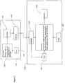
- the LAN 100 includes a file server 120, workstations 150, printers 180 and a Host 110b coupled to one another via network communications lines 160.
- the file server 120 and workstations 150 are preferably those well known in the art, such as computers having Intel Corporation (Santa Clara, California) microprocessors and running Microsoft Corporation (Redmond, Washington) Windows operating systems.
- An MFP 110a is coupled to the Host 110b.
- the LAN 100 may also include hubs, routers and other devices (not shown).
- the remote monitoring computer 170 coupled to the Host 110b by a public switched telephone network 130.
- the remote monitoring computer 170 and public switched telephone network 130 are not part of the LAN 100.
- the remote monitoring computer 170 is preferably generally as known in the art having an Intel microprocessor and running Microsoft Windows, but also having special programs for interaction with the Host 110b as set forth below.
- file server it is meant a computer which controls access to file and disk resources on a network, and provides security and synchronization on the network through a network operating system.
- server it is meant hardware or software which provides network services.
- workstation it is meant a client computer which routes commands either to its local operating system or to a network interface adapter for processing and transmission on the network.
- a workstation may function as a server by including appropriate software, and may be for example, a print server, archive server or communication server.
- software it is meant one or more computer interpretable programs and modules related and preferably integrated for performing a desired function.
- a “multifunction peripheral” is a peripheral which provides the functions of more than one peripheral, and typically provides printing and at least one of: copying, scanning and faxing.
- the MFP 110a preferably comprises a high output digital copier having a communications interface 215 preferably SCSI) and a hardware and software interface which allows the MFP 110a to receive rasterized print jobs from the Host 110b, manage the print jobs as well as its own copy jobs, and print the print jobs.
- the hardware includes a non-volatile data storage device 290 (preferably ROM or EPROM) and processor 235 in which programs are stored and run, respectively, for controlling the functions of the MFP 110a.
- the MFP 110a preferably also includes a short term rewritable data storage device 255 such as a RAM.
- the MFP 110a also includes a non-volatile rewritable data storage device 245 such as an NVRAM for storage of various information, include information regarding the status of operation of the MFP 110a.
- the MFP 110a includes standard components including automatic document feeder 275, paper bin 270 and paper output tray 295.
- the MFP 110a includes a non-fixed display 280, preferably an LCD, and user input device 285, such as button switches.
- the MFP 110a has user interface software stored in the data storage device 290 which is responsible for displaying information on the display 280 and interpreting user inputs from the user input device 285.
- the Host 110b preferably comprises a server such as a computer having an Intel processor 230 and running Microsoft Windows NT. To maximize efficiency, there is preferably a one-to-one correspondence between Hosts and MFPs.
- the Host 110b has a short term rewritable data storage device 220 (preferably RAM) and a non-volatile rewritable data storage device 240 (preferably a hard disk) as known in the art.
- the Host 110b further includes a communications interface 210 through which the Host 110b communicates with the MFP 110a through a channel 205.
- the communications interface 210 is configured as a SCSI host.
- the Host 110b further preferably includes a fax/modem 260 for sending and receiving faxes via telephone lines 130 and for communicating with the remote monitoring computer 170.
- the Host 110b includes management software stored in the long term data storage device 240 for managing print jobs, fax jobs and scan jobs.
- the Host 110b rasterizes print jobs from the LAN 100 into print data (a form native to the MFP 110a) and transmits the print data to the MFP 110a via the communications channel 205.
- the Host preferably also has a removable storage device 250 such as a floppy drive which uses a removable storage medium such as a floppy disk (not shown).
- the MFP's processor 235 under programmed control, is responsible for monitoring the condition of the MFP and updating a status information table stored in the non-volatile rewritable data storage device 245.
- the MFP's processor 235 operates in accordance with a clock 310 in the MFP 110a.
- Table 1 below sets forth a list of the MFP status conditions which are preferably included in the status table.
- the processor 235 monitors the user input device 285, and upon a predefined entry in the user input device 285, the processor 235 displays the selected status information from the data storage device 245 on the display 280.
- the processor 235 also utilizes a number of settings for the MFP's basic operating characteristics. Table 2 below sets forth a list of the preferred MFP 110a settings. Status Condition Value Range Initial Value Comments Auto-toner automatic adjustment (heat roller lamp ON) - - Auto-toner sensor initial value adjustment 0-255 127 Developing bias DC adjustment (Developing bias DC: ON) 0-255 128 Grid voltage initial value adjustment (Main motor, discharger, charger, grid: ON) 0-255 128 Transfer transformer DC output, high Center and low adjustments 0-255 160 Separation AC output, high, center and low adjustments 0-255 128 Cleaner pre-discharging AC output adjustment 0-255 128 Laser automatic adjustment 0-255 - Laser sharpness, minimum, maximum and center values 0-255 127 Scanner secondary scan magnification 0-255 127 Scanner secondary scan displacement 0-255 127 CCD primary scan displacement 0-255 128 Halogen lamp lighting voltage setting 0-15 8 White shading value display - Original document edge image cut - Basic PPC 0-255 127
- the Host 110b has its own clock 320.
- the Host's processor operating in accordance with the clock 320, is responsible for periodically initiating a refresh of a status information database in the long term data storage device 240.
- This status information is obtained from the MFP 110a and stored in a database preferably in the non-volatile rewritable data storage device 240.
- the Host's fax/modem 260 is used for communicating status information to the remote monitoring computer 170.
- the fax/modem 260 is also used for sending fax jobs from the workstations 150 or originating from the MFP 110a, as well as receiving faxes which are generally printed by the MFP 110a.
- the processor 230 also tests the status of the fax/modem 260 before use and preferably queues outbound traffic. Preferably, notification has a higher priority than outbound faxes.
- the Host 110b not only obtains the multifunction peripheral status information from the MFP's non-volatile rewritable data storage device 245 and stores this information in the database, but the processor 230, under programmed control also maintains in the database a history of this status information, including a log of significant operational events in the MFP 110a.
- the Host 110b also preferably monitors and stores in the database information regarding the number of users who have submitted print and fax jobs, the number of print and fax jobs submitted per user, the average total print time for print and fax jobs over a selected time frame, version information of Host 110b software, and information concerning the Host's "health,” status, resource allocation and usage statistics.
- the technician when using the remote monitoring workstation 170 to connect with the Host 110b, can also modify some or all of the settings in Table 2 (depending on permissions granted).
- the remote monitoring workstation 170 can also be used to upload new versions of Host 110b software, including new versions of user interface information which are used by the Host 110b in conjunction with the MFP 110a.
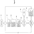
- the process is embodied as a program stored in the non-volatile rewritable data storage device 240 and loaded into and run by the processor 230.
- the program allows a technician to select a number of MFP status conditions to monitor (step 420). Preferably, this is accomplished by the technician accessing the Host 110b from a workstation 150 on the LAN 100 or the remote monitoring computer 170 via modem 260. Preferably, the technician may be notified of any of the status conditions in Table 1 and Table 2, and there is an option to provide the entire database.
- step 425 the technician is allowed to designate a notification method.
- This preferably comprises designating the telephone number of the remote monitoring computer 170, but might also include designating a workstation 150 on the LAN 100 to be notified.
- saving to the removable storage medium may also be selected as the notification method.
- the program allows the technician to select a number of trigger conditions to trigger notification (step 430).
- the technician may select any of the status conditions in Table 1 and Table 2 to be used in these trigger conditions.
- the technician preferably may select particular values at which a trigger condition is to be met. For example, the technician might want to be notified when the fuser counter reaches a particular value.
- the technician may select an increment for notification, such as to be notified every time the fuser counter reaches another thousand counts.
- the technician may select as a trigger condition an immediate call back.
- a trigger condition would be useful where the technician use the remote monitoring computer 170 through a long distance telephone connection, and desires the Host to initiate the call to reduce the technician's costs.
- the processor 230 preferably resets those trigger conditions needing to be reset (step 435). For example, incremental counters and temperature conditions are preferably reset.
- the processor 230 begins a monitoring and notification loop.
- the loop begins (step 440) with the Host's processor 230 periodically generating a signal to the MFP's processor 235 via the communications interface 210, the communications channel 205 and the communications interface 215 to request that the MFP's processor 235 to provide the status information stored in the data storage device 245.
- this step 440 is performed at a predetermined frequency in accordance with the clock 310 and a predetermined setting.
- the MFP's processor 235 is preferably also performing a programmed loop. Referring now to Figure 5, there is shown a flow chart of an MFP 110a process in accordance with the invention. After the program is started (step 510), the processor 235 determines a condition of plural predetermined operating aspects of the MFP 110a (step 520). The processor 235 derives status information regarding the condition of the multifunction peripheral (step 540), and updates the table in the non-volatile rewritable data storage device 245 with the status information (step 540).
- step 550 If the MFP 110a is to be shut down (step 550), the process will of course terminate (step 595). There may also be other reasons for stopping the process.
- step 570 the processor 235 checks if the Host 110b has requested the current status information (in step 445 of Figure 4). If so, then the processor 235 reads the status information from the data storage device 245 and transmits the status information via the communications interface 215 to the Hosts's processor 230. In either case, the loop continues by returning to step 520.
- the Host's processor 230 uses this status information to update the Host's MFP status database stored in the data storage device 240 (step 445).
- step 450 if the Host 110b is to be shut down (step 450), the process will of course terminate (step 495). There may also be other reasons for stopping the process.
- the processor 230 analyzes the status information database (step 455) and determines if any of the trigger conditions have been met (step 460). If not, then the loop continues at step 440.
- the processor 230 initiates a notification as indicated in the settings received in step 425 (step 465).
- this comprises the Host 110b using its modem 260 for connecting to the remote monitoring computer 170 and uploading the status information selected by the technician.
- the status information is provided to the remote monitoring computer 170 in ASCII format or in a format native to the database.
- the Host 110b preferably stores the status information regarding the conditions the technician selected for monitoring on the removable storage medium (step 475).
- the processor 230 After notifying the remote monitoring computer 170 (or saving to the removable storage medium), the processor 230 preferably resets those trigger conditions needing to be reset (step 480).
Abstract
Description


| Status Condition | Value Range | Initial Value | Comments |
| Auto-toner automatic adjustment (heat roller lamp ON) | - | - | |
| Auto-toner sensor initial value adjustment | 0-255 | 127 | |
| Developing bias DC adjustment (Developing bias DC: ON) | 0-255 | 128 | |
| Grid voltage initial value adjustment (Main motor, discharger, charger, grid: ON) | 0-255 | 128 | |
| Transfer transformer DC output, high Center and low adjustments | 0-255 | 160 | |
| Separation AC output, high, center and low adjustments | 0-255 | 128 | |
| Cleaner pre-discharging AC output adjustment | 0-255 | 128 | |
| Laser automatic adjustment | 0-255 | - | |
| Laser sharpness, minimum, maximum and center values | 0-255 | 127 | |
| Scanner secondary scan magnification | 0-255 | 127 | |
| Scanner secondary scan displacement | 0-255 | 127 | |
| CCD primary scan displacement | 0-255 | 128 | |
| Halogen lamp lighting voltage setting | 0-15 | 8 | |
| White shading value display | - | ||
| Original document edge image cut - Basic PPC | 0-255 | 127 | Basic PPC |
| Original document edge image cut - Expansion PPC | 0-255 | 127 | Expansion PPC |
| Original document edge void gradation | 0-255 | 128 | |
| Secondary scan magnification, main and resist motors speed fine adjustment | 0-255 | 127 | PPC |
| Laser firing position 0-255 | 127 | ||
| Margins - Basic and Expansion PPC | 0-255 | 127 | |
| Leading edge positions | 0-255 | 127 | |
| Aligning quantities | 0-255 | 127 | |
| Manual intensity fine adjustments | 0-255 | 127 | |
| Auto intensity fine adjustments | 0-255 | 127 | |
| User intensity center curve setting | [(-128) - (127)] x 17 | ||
| User intensity center curve selections | 0-15 | 0 | |
| Foundation cut quantity fine adjustments | 0-255 | 255 | |
| Black standard value offset quantities | 0-255 | 255 | |
| Range correction B/W standard values | 0-255 | 0 | |
| Foundation range width adjustments | 0-15 | 0 | |
| Gamma correction | - | ||
| Coefficient setting for LPF and HPF | 0-255 x 4 | 0 x4 | |
| LPF and HPF settings for various enlargement/reduction modes | 0-255 | 0 | |
| Enlargement/reduction random interpolation | 0-63 | 0 | |
| During smoothing ON Halftone judgement threshold value | 0-255 | 13 |
Claims (23)
- A data processing system for printing print jobs originating from workstations on a computer network, for copying copy jobs and for scanning scan jobs to the workstations, the data processing system comprising:(a) a multifunction peripheral for printing, copying and scanning, the multifunction peripheral comprising a paper tray, a display, a user input device, a first processor, a first data storage device for multifunction peripheral program storage, a second rewritable data storage device for short term storage and a third non-volatile rewritable data storage device, a first communications interface and a first clock for generating a first clock signal to the first processor, wherein the multifunction peripheral programs include instructions for causing the first processor to:(i) determine an operating condition of plural predetermined aspects of the multifunction peripheral,(ii) derive status information regarding the operating condition of the multifunction peripheral,(iii) update the third non-volatile rewritable data storage device with the status information,(iv) read the status information from the third data storage device and transmit the status information via the first communications interface; and(b) a Host for sending print jobs to the multifunction peripheral for printing and for receiving scan jobs, the Host comprising a second processor, a fourth rewritable non-volatile data storage device for storing Host programs and data and a fifth rewritable memory for short term storage, a second communications interface coupled to the communications interface of the multifunction peripheral by a communications channel, a third communications interface for communicating with a remote monitoring computer and a first clock for generating a second clock signal to the second processor, wherein the Host programs include instructions for causing the second processor to:(i) allow a technician to select plural status conditions of the multifunction peripheral to monitor,(ii) allow the technician to designate a notification method for the remote monitoring computer,(iii) allow the technician to define plural trigger conditions to trigger notification of the remote monitoring computer,(iv) periodically generate a signal to the first processor via the second communications interface, the communications channel and the first communications interface to request that first processor provide the multifunction peripheral status information stored in the third data storage device,(v) refresh a status information database in the fourth rewritable non-volatile data storage device from the status information received from the third data storage device in the multifunction peripheral, and(vi) analyze the status information database to detect if any of the selected trigger conditions have been met, and if so, then initiate a notification of the remote monitoring computer through the third communications interface for providing the status information regarding the status conditions the technician selected for monitoring.
- A data processing system as set forth in claim 1, the Host further comprising a removable storage device and a removable storage medium, and if the Host is unable to connect with the remote monitoring computer, then the Host stores the status information regarding the status conditions the technician selected for monitoring on the removable storage medium.
- A data processing system as set forth in claim 2, the removable storage medium comprising a floppy disk and the removable storage device comprising a floppy drive.
- A data processing system as set forth in claim 1, wherein the third data storage device comprises an NVRAM.
- A data processing system as set forth in claim 1, wherein the first data storage device further includes programs for causing the processor to monitor the user input device, and upon a predefined entry in the user input device, to display the selected status information on the display.
- A data processing system as set forth in claim 1, wherein the second processor sends the status information to the remote monitoring computer in ASCII format.
- A data processing system as set forth in claim 1, wherein the processor sends the status information to the remote monitoring computer in a database format.
- A data processing system as set forth in claim 7, wherein the Host transmits the entire status information database to the remote monitoring computer.
- A data processing system as set forth in claim 1, wherein the third communications interface comprises a modem.
- A data processing system as set forth in claim 1, wherein the first communications interface and second communications interface comprise SCSI interfaces.
- A data processing system as set forth in claim 1, wherein the status information includes any of the items in Table 1 and Table 2.
- A data processing system as set forth in claim 1, wherein the trigger conditions may regard any of the items in Table 1 and Table 2.
- A data processing system as set forth in claim 1, wherein the database include a history of multifunction peripheral events.
- A method of notifying a remote monitoring computer of the status of a multifunction peripheral, the multifunction peripheral for printing, copying and scanning, the multifunction peripheral comprising a paper tray, a display, a user input device, a first processor, a first data storage device for multifunction peripheral program storage, a second rewritable data storage device for short term storage and a third non-volatile rewritable data storage device, a first communications interface and a first clock for generating a first clock signal to the first processor, the Host for sending print jobs to the multifunction peripheral for printing and for receiving scan jobs, the Host comprising a second processor, a fourth rewritable non-volatile data storage device for storing Host programs and data and a fifth rewritable memory for short term storage, a second communications interface coupled to the communications interface of the multifunction peripheral by a communications channel, a third communications interface for communicating with a remote monitoring computer and a first clock for generating a second clock signal to the second processor, the method comprising:(a) in the multifunction peripheral, performing the steps of:(i) determining an operating condition of plural predetermined aspects of the multifunction peripheral,(ii) deriving status information regarding the operating condition of the multifunction peripheral,(iii) updating the third non-volatile rewritable data storage device with the status information, and(iv) reading the status information from the third data storage device and transmit the status information via the first communications interface; and(b) in the Host, performing the steps of:(i) allowing a technician to select plural status conditions of the multifunction peripheral to monitor,(ii) allowing the technician to designate a notification method for the remote monitoring computer,(iii) allowing the technician to select plural trigger conditions to trigger notification of the remote monitoring computer,(iv) periodically generating a signal to the first processor via the second communications interface, the communications channel and the first communications interface to request that first processor provide the multifunction peripheral status information stored in the third data storage device,(v) refreshing a status information database in the fourth rewritable non-volatile data storage device from the status information received from the third data storage device in the multifunction peripheral, and(vi) analyzing the status information database to detect if any of the trigger conditions have been met, and if so, then initiating a notification of the remote monitoring computer through the third communications interface for providing the status information regarding the status conditions the technician selected for monitoring.
- A method of notifying a remote monitoring computer of the status of a multifunction peripheral as set forth in claim 14, the Host further comprising a removable storage device and a removable storage medium, the method further comprising, if the Host is unable to connect with the remote monitoring computer, then the Host storing the status information regarding the status conditions the technician selected for monitoring on the removable storage medium.
- A method of notifying a remote monitoring computer of the status of a multifunction peripheral as set forth in claim 15, the removable storage medium comprising a floppy disk and the removable storage device comprising a floppy drive.
- A method of notifying a remote monitoring computer of the status of a multifunction peripheral as set forth in claim 14, the method further comprising, in the multifunction peripheral, monitoring the user input device, and upon a predefined entry in the user input device, displaying the selected status information on the display.
- A method of notifying a remote monitoring computer of the status of a multifunction peripheral as set forth in claim 14, further comprising, in the Host, sending the status information to the remote monitoring computer in ASCII format.
- A method of notifying a remote monitoring computer of the status of a multifunction peripheral as set forth in claim 14, further comprising, in the Host, sending the status information to the remote monitoring computer in a database format.
- A method of notifying a remote monitoring computer of the status of a multifunction peripheral as set forth in claim 19, wherein the Host transmits the entire status information database to the remote monitoring computer.
- A method of notifying a remote monitoring computer of the status of a multifunction peripheral as set forth in claim 14, wherein the status information includes any of the items in Table 1 and Table 2.
- A method of notifying a remote monitoring computer of the status of a multifunction peripheral as set forth in claim 14, further comprising, in the Host, sending , wherein the trigger conditions may regard any of the items in Table 1 and Table 2.
- A method of notifying a remote monitoring computer of the status of a multifunction peripheral as set forth in claim 14, further comprising, in the Host, storing in the database a history of multifunction peripheral events.
Applications Claiming Priority (2)
| Application Number | Priority Date | Filing Date | Title |
|---|---|---|---|
| US08/800,859 US6108492A (en) | 1997-02-14 | 1997-02-14 | Remote monitoring system |
| US800859 | 1997-02-14 |
Publications (3)
| Publication Number | Publication Date |
|---|---|
| EP0859489A2 true EP0859489A2 (en) | 1998-08-19 |
| EP0859489A3 EP0859489A3 (en) | 1999-06-02 |
| EP0859489B1 EP0859489B1 (en) | 2005-01-12 |
Family
ID=25179563
Family Applications (1)
| Application Number | Title | Priority Date | Filing Date |
|---|---|---|---|
| EP98100707A Expired - Lifetime EP0859489B1 (en) | 1997-02-14 | 1998-01-16 | Remote monitoring system |
Country Status (6)
| Country | Link |
|---|---|
| US (1) | US6108492A (en) |
| EP (1) | EP0859489B1 (en) |
| JP (1) | JP3238122B2 (en) |
| CN (1) | CN1201208A (en) |
| CA (1) | CA2227114C (en) |
| DE (1) | DE69828538T2 (en) |
Cited By (15)
| Publication number | Priority date | Publication date | Assignee | Title |
|---|---|---|---|---|
| EP1244285A1 (en) * | 2001-03-15 | 2002-09-25 | Ricoh Company, Ltd. | Nonvolatile memory life prolonging circuit and image forming apparatus |
| EP1445931A3 (en) * | 2003-02-07 | 2005-12-28 | Canon Kabushiki Kaisha | Data transfer method |
| WO2009037426A3 (en) * | 2007-09-17 | 2009-06-04 | The Technology Partnership Plc | Configurable module |
| US7711814B1 (en) | 2004-12-13 | 2010-05-04 | American Power Conversion Corporation | Method and system for remote monitoring of a power supply device with user registration capability |
| US7779026B2 (en) | 2002-05-03 | 2010-08-17 | American Power Conversion Corporation | Method and apparatus for collecting and displaying network device information |
| US7986224B2 (en) | 2003-04-14 | 2011-07-26 | American Power Conversion Corporation | Environmental monitoring device |
| US8015255B2 (en) | 2003-10-27 | 2011-09-06 | American Power Conversion Corporation | System and method for network device communication |
| US8024451B2 (en) | 1999-10-27 | 2011-09-20 | American Power Conversion Corporation | Method and system for monitoring computer networks and equipment |
| US8145748B2 (en) | 2004-12-13 | 2012-03-27 | American Power Conversion Corporation | Remote monitoring system |
| US8224953B2 (en) | 1999-10-27 | 2012-07-17 | American Power Conversion Corporation | Method and apparatus for replay of historical data |
| US8271626B2 (en) | 2001-01-26 | 2012-09-18 | American Power Conversion Corporation | Methods for displaying physical network topology and environmental status by location, organization, or responsible party |
| US8566292B2 (en) | 2003-04-14 | 2013-10-22 | Schneider Electric It Corporation | Method and system for journaling and accessing sensor and configuration data |
| US8990536B2 (en) | 2011-06-01 | 2015-03-24 | Schneider Electric It Corporation | Systems and methods for journaling and executing device control instructions |
| US9952103B2 (en) | 2011-12-22 | 2018-04-24 | Schneider Electric It Corporation | Analysis of effect of transient events on temperature in a data center |
| US11076507B2 (en) | 2007-05-15 | 2021-07-27 | Schneider Electric It Corporation | Methods and systems for managing facility power and cooling |
Families Citing this family (57)
| Publication number | Priority date | Publication date | Assignee | Title |
|---|---|---|---|---|
| US7428575B1 (en) * | 1998-11-17 | 2008-09-23 | Ricoh Company, Ltd. | Method and system for communicating with a device attached to a computer using electronic mail messages |
| US6266693B1 (en) * | 1998-08-31 | 2001-07-24 | Toshiba America Information Systems Inc. | Method of controlling printer information in a network environment |
| US6292271B1 (en) * | 1998-09-03 | 2001-09-18 | Toshiba American Information Systems, Inc. | Soft labels for MFP panel display |
| JP2000132365A (en) * | 1998-10-28 | 2000-05-12 | Fujitsu Ltd | Peripheral device management device, peripheral device connected to the same and peripheral device managing method |
| US7376728B1 (en) * | 2000-07-25 | 2008-05-20 | Ricoh Company, Ltd. | Method and system for monitoring, collecting information, diagnosing and servicing a remote system |
| US6665085B1 (en) * | 1999-05-25 | 2003-12-16 | Xerox Corporation | Simultaneous voice and data communication for diagnostic procedures in a printing or copying machine |
| US6487521B1 (en) * | 1999-07-07 | 2002-11-26 | International Business Machines Corporation | Method, system, and program for monitoring a device to determine a power failure at the device |
| US8055752B1 (en) * | 1999-11-16 | 2011-11-08 | Ricoh Company, Ltd. | Application unit monitoring and reporting system and method with usage data logged into a map structure |
| US6285835B1 (en) * | 2000-01-11 | 2001-09-04 | Hewlett-Packard Company | Utilizing printer memory for automatic user messaging |
| US6754759B1 (en) * | 2000-03-08 | 2004-06-22 | Intel Corporation | Transfer of information between devices on different buses |
| JP4403335B2 (en) * | 2000-04-17 | 2010-01-27 | ソニー株式会社 | Maintenance support system for video processing equipment |
| US6370340B1 (en) * | 2000-05-17 | 2002-04-09 | Heidelberg Digital, L.L.C. | Method and apparatus for monitoring parameters corresponding to operation of an electrophotographic marking machine |
| US6366744B1 (en) * | 2000-06-22 | 2002-04-02 | Hewlett-Packard Company | Image forming systems and methods for determining whether an image job will be imaged |
| US7117239B1 (en) | 2000-07-28 | 2006-10-03 | Axeda Corporation | Reporting the state of an apparatus to a remote computer |
| JP2002073954A (en) * | 2000-08-24 | 2002-03-12 | Nec Corp | Sales promotion system and method for computer peripheral device |
| US8108543B2 (en) | 2000-09-22 | 2012-01-31 | Axeda Corporation | Retrieving data from a server |
| US7185014B1 (en) | 2000-09-22 | 2007-02-27 | Axeda Corporation | Retrieving data from a server |
| US7392307B2 (en) * | 2001-02-14 | 2008-06-24 | Ricoh Co., Ltd. | Method and system of remote diagnostic, control and information collection using a shared resource |
| US7505914B2 (en) * | 2001-08-06 | 2009-03-17 | Ecolab Inc. | Method and system for providing advisory information to a field service provider |
| JP2003066774A (en) * | 2001-08-24 | 2003-03-05 | Canon Inc | Image forming device and self-diagnostic system |
| JP2003099380A (en) * | 2001-09-26 | 2003-04-04 | Toyota Keeramu:Kk | Inter-system communication method, program for computer and interface module |
| JP2003118205A (en) * | 2001-10-09 | 2003-04-23 | Brother Ind Ltd | Network terminal |
| CN1151415C (en) * | 2001-10-23 | 2004-05-26 | 深圳市朗科科技有限公司 | Method for adding additional memory function to periphrals of computer and its architecture |
| US7742182B2 (en) | 2001-10-23 | 2010-06-22 | Hewlett-Packard Development Company, L.P. | System and method of identifying a printer output tray |
| US6985675B2 (en) * | 2001-12-06 | 2006-01-10 | Hewlett-Packard Development Company, L.P. | Image forming devices, methods of operating an image forming device and methods of monitoring an environment proximate to an image forming device |
| US7254601B2 (en) | 2001-12-20 | 2007-08-07 | Questra Corporation | Method and apparatus for managing intelligent assets in a distributed environment |
| US7178149B2 (en) | 2002-04-17 | 2007-02-13 | Axeda Corporation | XML scripting of soap commands |
| US7152107B2 (en) * | 2002-08-07 | 2006-12-19 | Hewlett-Packard Development Company, L.P. | Information sharing device |
| US6889264B2 (en) * | 2002-10-09 | 2005-05-03 | Hewlett-Packard Development Company, L.P. | Imposing a delay for indication of a status board to provide a time for self-rectification of a service event detected from peripheral status information |
| US20060190725A1 (en) * | 2002-10-15 | 2006-08-24 | Zezhen Huang | Method and system for measuring productivity based on computer activities |
| JP2004234645A (en) * | 2003-01-10 | 2004-08-19 | Canon Inc | Monitoring device of image forming apparatus, control method by the monitoring device, program for executing the control method, management device, control method by the management device, and program for executing control method |
| US7966418B2 (en) | 2003-02-21 | 2011-06-21 | Axeda Corporation | Establishing a virtual tunnel between two computer programs |
| US7298512B2 (en) * | 2003-03-26 | 2007-11-20 | Hewlett-Packard Development Company, L.P. | Printing device with embedded database connector |
| JP2004333694A (en) * | 2003-05-02 | 2004-11-25 | Fuji Photo Film Co Ltd | Image recording processing method and thermal developing recording device |
| US20050097198A1 (en) * | 2003-10-08 | 2005-05-05 | Getler Robert M. | Printer monitoring system and method |
| US20050097199A1 (en) | 2003-10-10 | 2005-05-05 | Keith Woodard | Method and system for scanning network devices |
| CN100363920C (en) * | 2004-03-23 | 2008-01-23 | 英特维数位科技股份有限公司 | Computer system for storing long-distance visual information and method thereof |
| US7069856B2 (en) * | 2004-05-13 | 2006-07-04 | Sun Automation, Inc. | Method and apparatus for managing box-finishing machine |
| JP4328672B2 (en) * | 2004-06-01 | 2009-09-09 | キヤノン株式会社 | Information processing apparatus and device |
| JP2006047998A (en) * | 2004-06-30 | 2006-02-16 | Ricoh Co Ltd | Image forming apparatus and control method of image forming apparatus |
| JP2006033315A (en) * | 2004-07-15 | 2006-02-02 | Evolium Sas | Network monitoring system |
| US20060152759A1 (en) * | 2005-01-13 | 2006-07-13 | Yen-Fu Chen | Method and system for real-time end-user status and quality monitoring of printing operations |
| US20070061460A1 (en) * | 2005-03-24 | 2007-03-15 | Jumpnode Systems,Llc | Remote access |
| JP4766667B2 (en) * | 2005-08-29 | 2011-09-07 | キヤノン株式会社 | Display control apparatus, control method therefor, and program |
| JP2007334741A (en) * | 2006-06-16 | 2007-12-27 | Konica Minolta Business Technologies Inc | Management method of event information on event caused in image forming apparatus, and server computer |
| US8356244B2 (en) * | 2006-06-20 | 2013-01-15 | The Boeing Company | Managing changes in aircraft maintenance data |
| US8370479B2 (en) | 2006-10-03 | 2013-02-05 | Axeda Acquisition Corporation | System and method for dynamically grouping devices based on present device conditions |
| US8065397B2 (en) | 2006-12-26 | 2011-11-22 | Axeda Acquisition Corporation | Managing configurations of distributed devices |
| EP1970800A1 (en) * | 2007-03-15 | 2008-09-17 | Brandgroup GmbH | Method for creating control data to manufacture a product |
| US20080309965A1 (en) * | 2007-06-14 | 2008-12-18 | Dex Imaging | Apparatus and method for discovering printers within an enterprise |
| US8478861B2 (en) | 2007-07-06 | 2013-07-02 | Axeda Acquisition Corp. | Managing distributed devices with limited connectivity |
| US20090187413A1 (en) * | 2008-01-18 | 2009-07-23 | Timothy Abels | Service delivery platform for automated and remote information technology management |
| US8330984B2 (en) * | 2010-03-18 | 2012-12-11 | Emerge Paint Management, LLC | Field metering patrol system and method for metering and monitoring printers |
| US8314965B2 (en) * | 2010-03-18 | 2012-11-20 | Emerge Print Management, Llc | Patrol device field installation notification method and system |
| US20120023027A1 (en) * | 2010-07-22 | 2012-01-26 | Xerox Corporation | Automated method and system for print head warranty verification |
| JP2015079186A (en) * | 2013-10-18 | 2015-04-23 | 富士ゼロックス株式会社 | Control device, image forming apparatus, and program |
| JP6379783B2 (en) * | 2014-07-17 | 2018-08-29 | 富士ゼロックス株式会社 | Information processing apparatus, information processing system, and information processing program |
Citations (3)
| Publication number | Priority date | Publication date | Assignee | Title |
|---|---|---|---|---|
| US5353399A (en) * | 1989-11-08 | 1994-10-04 | Hitachi, Ltd. | Method and system for selecting devices in information networks, including inputting/outputting data to a specified device selected by pointing to a corresponding indicator on a screen |
| EP0745929A1 (en) * | 1995-05-30 | 1996-12-04 | Canon Kabushiki Kaisha | Adaptive graphical user-interface for a network peripheral |
| EP0749065A1 (en) * | 1995-06-12 | 1996-12-18 | Xerox Corporation | Apparatus and method of automatically transmitting event-related information to a user of a network printing system |
Family Cites Families (23)
| Publication number | Priority date | Publication date | Assignee | Title |
|---|---|---|---|---|
| US4186299A (en) * | 1977-08-30 | 1980-01-29 | Xerox Corporation | Reproduction machine with different operating programs |
| US4583834A (en) * | 1977-09-16 | 1986-04-22 | Ricoh Company, Ltd. | Copying apparatus |
| US5077582A (en) * | 1988-05-17 | 1991-12-31 | Monitel Products Corp. | Photocopy monitoring system |
| US5184179A (en) * | 1988-05-17 | 1993-02-02 | Monitel Products Corp. | Photocopy monitoring system and method for monitoring copiers |
| US5271045A (en) * | 1989-11-02 | 1993-12-14 | Combustion Engineering, Inc. | Advanced nuclear plant control complex |
| US5227121A (en) * | 1989-11-02 | 1993-07-13 | Combustion Engineering, Inc. | Advanced nuclear plant control room complex |
| US5267278A (en) * | 1989-11-02 | 1993-11-30 | Combustion Engineering, Inc. | Console for a nuclear control complex |
| US5265131A (en) * | 1989-11-02 | 1993-11-23 | Combustion Engineering, Inc. | Indicator system for a process plant control complex |
| US5084875A (en) * | 1989-12-13 | 1992-01-28 | Joseph Weinberger | System for automatically monitoring copiers from a remote location |
| US5214772A (en) * | 1989-12-13 | 1993-05-25 | Joseph Weinberger | System for automatically monitoring copiers from a remote location |
| US5333286A (en) * | 1989-12-13 | 1994-07-26 | Joseph Weinberger | Two way copier monitoring system |
| CA2009148C (en) * | 1990-02-01 | 1998-03-10 | Robert H. Bayne | Computer based system timer (cbst) |
| US5057866A (en) * | 1990-05-04 | 1991-10-15 | Xerox Corporation | Remotely accessible copier calculator |
| US5440301A (en) * | 1990-05-14 | 1995-08-08 | Evans; Wayne W. | Intelligent alerting and locating communication system |
| US5384622A (en) * | 1991-11-18 | 1995-01-24 | Minolta Camera Kabushiki Kaisha | System of controlling a plurality of copying machines interconnnected through a private branch exchange |
| DE69318259T2 (en) * | 1992-11-18 | 1998-09-17 | Canon Kk | Method and device for implementing a two-way interface between a local network and a peripheral device |
| US5305055A (en) * | 1992-12-16 | 1994-04-19 | Xerox Corporation | Automatic call to selected remote operators in response to predetermined machine conditions |
| US5491473A (en) * | 1993-03-31 | 1996-02-13 | Euro Cp S.A.R.L. | System for remote data collecting, method implemented in this system and data collector device |
| US5365310A (en) * | 1993-07-30 | 1994-11-15 | Xerox Corporation | Remote diagnosis of copy quality defects |
| US5493287A (en) * | 1994-03-07 | 1996-02-20 | Motorola, Inc. | Method of remotely reading a group of meters |
| US5485142A (en) * | 1994-04-08 | 1996-01-16 | The United States Of America As Represented By The Administrator Of The National Aeronautics And Space Administration | Remote monitor alarm system |
| US5502543A (en) * | 1994-06-28 | 1996-03-26 | Xerox Corporation | System for collecting statistical data on remotely monitored machines |
| US5446672A (en) * | 1994-08-09 | 1995-08-29 | Air Gage Company | Machine monitoring system |
-
1997
- 1997-02-14 US US08/800,859 patent/US6108492A/en not_active Expired - Lifetime
-
1998
- 1998-01-15 CA CA002227114A patent/CA2227114C/en not_active Expired - Fee Related
- 1998-01-16 DE DE69828538T patent/DE69828538T2/en not_active Expired - Fee Related
- 1998-01-16 EP EP98100707A patent/EP0859489B1/en not_active Expired - Lifetime
- 1998-02-13 CN CN98106432A patent/CN1201208A/en active Pending
- 1998-02-16 JP JP3303598A patent/JP3238122B2/en not_active Expired - Fee Related
Patent Citations (3)
| Publication number | Priority date | Publication date | Assignee | Title |
|---|---|---|---|---|
| US5353399A (en) * | 1989-11-08 | 1994-10-04 | Hitachi, Ltd. | Method and system for selecting devices in information networks, including inputting/outputting data to a specified device selected by pointing to a corresponding indicator on a screen |
| EP0745929A1 (en) * | 1995-05-30 | 1996-12-04 | Canon Kabushiki Kaisha | Adaptive graphical user-interface for a network peripheral |
| EP0749065A1 (en) * | 1995-06-12 | 1996-12-18 | Xerox Corporation | Apparatus and method of automatically transmitting event-related information to a user of a network printing system |
Non-Patent Citations (1)
| Title |
|---|
| HAYES F: "THE PRINTERS TALK BACK" BYTE, vol. 18, no. 13, 1 December 1993, page 103/104, 106, 108, 110 XP000414930 * |
Cited By (23)
| Publication number | Priority date | Publication date | Assignee | Title |
|---|---|---|---|---|
| US8024451B2 (en) | 1999-10-27 | 2011-09-20 | American Power Conversion Corporation | Method and system for monitoring computer networks and equipment |
| US8224953B2 (en) | 1999-10-27 | 2012-07-17 | American Power Conversion Corporation | Method and apparatus for replay of historical data |
| US8090817B2 (en) | 1999-10-27 | 2012-01-03 | American Power Conversion Corporation | Method and system for monitoring computer networks and equipment |
| US8966044B2 (en) | 2001-01-26 | 2015-02-24 | Schneider Electric It Corporation | Methods for displaying physical network topology and environmental status by location, organization, or responsible party |
| US8271626B2 (en) | 2001-01-26 | 2012-09-18 | American Power Conversion Corporation | Methods for displaying physical network topology and environmental status by location, organization, or responsible party |
| US7221468B2 (en) | 2001-03-15 | 2007-05-22 | Ricoh Company, Ltd. | Nonvolatile memory life prolonging circuit and image forming apparatus |
| EP1244285A1 (en) * | 2001-03-15 | 2002-09-25 | Ricoh Company, Ltd. | Nonvolatile memory life prolonging circuit and image forming apparatus |
| US7779026B2 (en) | 2002-05-03 | 2010-08-17 | American Power Conversion Corporation | Method and apparatus for collecting and displaying network device information |
| US7958170B2 (en) | 2002-05-03 | 2011-06-07 | American Power Conversion Corporation | Method and apparatus for collecting and displaying data associated with network devices |
| US8019798B2 (en) | 2002-05-03 | 2011-09-13 | American Power Conversion Corporation | Method and apparatus for collecting and displaying network device information |
| US8719319B2 (en) | 2002-05-03 | 2014-05-06 | Schneider Electric It Corporation | Method and apparatus for collecting and displaying network device information |
| EP1445931A3 (en) * | 2003-02-07 | 2005-12-28 | Canon Kabushiki Kaisha | Data transfer method |
| US8566292B2 (en) | 2003-04-14 | 2013-10-22 | Schneider Electric It Corporation | Method and system for journaling and accessing sensor and configuration data |
| US7986224B2 (en) | 2003-04-14 | 2011-07-26 | American Power Conversion Corporation | Environmental monitoring device |
| US8015255B2 (en) | 2003-10-27 | 2011-09-06 | American Power Conversion Corporation | System and method for network device communication |
| US8145748B2 (en) | 2004-12-13 | 2012-03-27 | American Power Conversion Corporation | Remote monitoring system |
| US7711814B1 (en) | 2004-12-13 | 2010-05-04 | American Power Conversion Corporation | Method and system for remote monitoring of a power supply device with user registration capability |
| US9166870B2 (en) | 2004-12-13 | 2015-10-20 | Schneider Electric It Corporation | Remote monitoring system |
| US11076507B2 (en) | 2007-05-15 | 2021-07-27 | Schneider Electric It Corporation | Methods and systems for managing facility power and cooling |
| US11503744B2 (en) | 2007-05-15 | 2022-11-15 | Schneider Electric It Corporation | Methods and systems for managing facility power and cooling |
| WO2009037426A3 (en) * | 2007-09-17 | 2009-06-04 | The Technology Partnership Plc | Configurable module |
| US8990536B2 (en) | 2011-06-01 | 2015-03-24 | Schneider Electric It Corporation | Systems and methods for journaling and executing device control instructions |
| US9952103B2 (en) | 2011-12-22 | 2018-04-24 | Schneider Electric It Corporation | Analysis of effect of transient events on temperature in a data center |
Also Published As
| Publication number | Publication date |
|---|---|
| JPH10326168A (en) | 1998-12-08 |
| DE69828538T2 (en) | 2005-12-29 |
| CN1201208A (en) | 1998-12-09 |
| CA2227114C (en) | 2003-08-19 |
| US6108492A (en) | 2000-08-22 |
| EP0859489B1 (en) | 2005-01-12 |
| EP0859489A3 (en) | 1999-06-02 |
| DE69828538D1 (en) | 2005-02-17 |
| CA2227114A1 (en) | 1998-08-14 |
| JP3238122B2 (en) | 2001-12-10 |
Similar Documents
| Publication | Publication Date | Title |
|---|---|---|
| EP0859489B1 (en) | Remote monitoring system | |
| US6266693B1 (en) | Method of controlling printer information in a network environment | |
| EP0859309B1 (en) | System and Method of administering work group printers | |
| US6856416B1 (en) | Dynamic load balancing for a tandem printing system | |
| US6724494B1 (en) | Error management for a tandem printing system | |
| USRE42170E1 (en) | Control of information processing using one or more peripheral apparatus | |
| EP0859321B1 (en) | Multifunction peripheral controller | |
| EP0858022B1 (en) | Method of providing a user interface for a multifunction peripheral device and a multifunction peripheral device. | |
| US7177034B2 (en) | Print managing apparatus and print managing method | |
| US7058705B1 (en) | Processing method of device information and network device in device information management system | |
| US20080246993A1 (en) | Image processing apparatus, job management method for the same, and recording medium having recorded thereon job management program | |
| JP2004164157A (en) | Composite device management device, system, method and program | |
| US9875240B2 (en) | Report creating system, report creating apparatus, and report creating method | |
| JP2001345966A (en) | Printing system and its printing control method | |
| US20110279848A1 (en) | Image forming apparatus with power save mode learning function and method of managing power save mode in the image forming apparatus | |
| US8218169B2 (en) | Information processing apparatus, information processing method, job management system, and information processing program | |
| US8446608B2 (en) | Image forming apparatus and image forming system | |
| US20040220779A1 (en) | Device management system, printer management system, printer management terminal and program for terminal, and device management method | |
| US10592174B2 (en) | Information processing system, server and non-transitory computer-readable recording medium encoded with data distribution program | |
| JP3527380B2 (en) | Service providing system, its server and printer | |
| JP2004348294A (en) | Image processing device management system | |
| EP1962487B1 (en) | Image forming apparatus, image forming system and method to control the system | |
| JP4339025B2 (en) | Image forming apparatus management system, image forming apparatus, image state determination notification method, and program | |
| JP2001298573A (en) | Network scanner device, method for controlling network scanner reading and medium with network scanner control program recorded thereon | |
| JPH08293946A (en) | Office automation system |
Legal Events
| Date | Code | Title | Description |
|---|---|---|---|
| PUAI | Public reference made under article 153(3) epc to a published international application that has entered the european phase |
Free format text: ORIGINAL CODE: 0009012 |
|
| AK | Designated contracting states |
Kind code of ref document: A2 Designated state(s): DE FR GB NL SE |
|
| AX | Request for extension of the european patent |
Free format text: AL;LT;LV;MK;RO;SI |
|
| 17P | Request for examination filed |
Effective date: 19980706 |
|
| PUAL | Search report despatched |
Free format text: ORIGINAL CODE: 0009013 |
|
| AK | Designated contracting states |
Kind code of ref document: A3 Designated state(s): AT BE CH DE DK ES FI FR GB GR IE IT LI LU MC NL PT SE |
|
| AX | Request for extension of the european patent |
Free format text: AL;LT;LV;MK;RO;SI |
|
| AKX | Designation fees paid |
Free format text: DE FR GB NL SE |
|
| 17Q | First examination report despatched |
Effective date: 20040127 |
|
| GRAP | Despatch of communication of intention to grant a patent |
Free format text: ORIGINAL CODE: EPIDOSNIGR1 |
|
| GRAS | Grant fee paid |
Free format text: ORIGINAL CODE: EPIDOSNIGR3 |
|
| GRAA | (expected) grant |
Free format text: ORIGINAL CODE: 0009210 |
|
| AK | Designated contracting states |
Kind code of ref document: B1 Designated state(s): DE FR GB NL SE |
|
| PG25 | Lapsed in a contracting state [announced via postgrant information from national office to epo] |
Ref country code: NL Free format text: LAPSE BECAUSE OF FAILURE TO SUBMIT A TRANSLATION OF THE DESCRIPTION OR TO PAY THE FEE WITHIN THE PRESCRIBED TIME-LIMIT Effective date: 20050112 |
|
| REG | Reference to a national code |
Ref country code: GB Ref legal event code: FG4D |
|
| REF | Corresponds to: |
Ref document number: 69828538 Country of ref document: DE Date of ref document: 20050217 Kind code of ref document: P |
|
| PG25 | Lapsed in a contracting state [announced via postgrant information from national office to epo] |
Ref country code: SE Free format text: LAPSE BECAUSE OF FAILURE TO SUBMIT A TRANSLATION OF THE DESCRIPTION OR TO PAY THE FEE WITHIN THE PRESCRIBED TIME-LIMIT Effective date: 20050412 |
|
| NLV1 | Nl: lapsed or annulled due to failure to fulfill the requirements of art. 29p and 29m of the patents act | ||
| PLBE | No opposition filed within time limit |
Free format text: ORIGINAL CODE: 0009261 |
|
| STAA | Information on the status of an ep patent application or granted ep patent |
Free format text: STATUS: NO OPPOSITION FILED WITHIN TIME LIMIT |
|
| ET | Fr: translation filed | ||
| 26N | No opposition filed |
Effective date: 20051013 |
|
| PGFP | Annual fee paid to national office [announced via postgrant information from national office to epo] |
Ref country code: DE Payment date: 20090108 Year of fee payment: 12 |
|
| PGFP | Annual fee paid to national office [announced via postgrant information from national office to epo] |
Ref country code: GB Payment date: 20090114 Year of fee payment: 12 |
|
| PGFP | Annual fee paid to national office [announced via postgrant information from national office to epo] |
Ref country code: FR Payment date: 20090113 Year of fee payment: 12 |
|
| GBPC | Gb: european patent ceased through non-payment of renewal fee |
Effective date: 20100116 |
|
| REG | Reference to a national code |
Ref country code: FR Ref legal event code: ST Effective date: 20100930 |
|
| PG25 | Lapsed in a contracting state [announced via postgrant information from national office to epo] |
Ref country code: FR Free format text: LAPSE BECAUSE OF NON-PAYMENT OF DUE FEES Effective date: 20100201 |
|
| PG25 | Lapsed in a contracting state [announced via postgrant information from national office to epo] |
Ref country code: DE Free format text: LAPSE BECAUSE OF NON-PAYMENT OF DUE FEES Effective date: 20100803 |
|
| PG25 | Lapsed in a contracting state [announced via postgrant information from national office to epo] |
Ref country code: GB Free format text: LAPSE BECAUSE OF NON-PAYMENT OF DUE FEES Effective date: 20100116 |