EP0860581A1 - Drilling machine - Google Patents
Drilling machine Download PDFInfo
- Publication number
- EP0860581A1 EP0860581A1 EP97710006A EP97710006A EP0860581A1 EP 0860581 A1 EP0860581 A1 EP 0860581A1 EP 97710006 A EP97710006 A EP 97710006A EP 97710006 A EP97710006 A EP 97710006A EP 0860581 A1 EP0860581 A1 EP 0860581A1
- Authority
- EP
- European Patent Office
- Prior art keywords
- drilling
- elements
- gripper
- drill
- magazine
- Prior art date
- Legal status (The legal status is an assumption and is not a legal conclusion. Google has not performed a legal analysis and makes no representation as to the accuracy of the status listed.)
- Withdrawn
Links
Images


Classifications
-
- E—FIXED CONSTRUCTIONS
- E21—EARTH DRILLING; MINING
- E21B—EARTH DRILLING, e.g. DEEP DRILLING; OBTAINING OIL, GAS, WATER, SOLUBLE OR MELTABLE MATERIALS OR A SLURRY OF MINERALS FROM WELLS
- E21B19/00—Handling rods, casings, tubes or the like outside the borehole, e.g. in the derrick; Apparatus for feeding the rods or cables
- E21B19/14—Racks, ramps, troughs or bins, for holding the lengths of rod singly or connected; Handling between storage place and borehole
- E21B19/146—Carousel systems, i.e. rotating rack systems
-
- E—FIXED CONSTRUCTIONS
- E21—EARTH DRILLING; MINING
- E21B—EARTH DRILLING, e.g. DEEP DRILLING; OBTAINING OIL, GAS, WATER, SOLUBLE OR MELTABLE MATERIALS OR A SLURRY OF MINERALS FROM WELLS
- E21B19/00—Handling rods, casings, tubes or the like outside the borehole, e.g. in the derrick; Apparatus for feeding the rods or cables
- E21B19/14—Racks, ramps, troughs or bins, for holding the lengths of rod singly or connected; Handling between storage place and borehole
- E21B19/15—Racking of rods in horizontal position; Handling between horizontal and vertical position
-
- E—FIXED CONSTRUCTIONS
- E21—EARTH DRILLING; MINING
- E21B—EARTH DRILLING, e.g. DEEP DRILLING; OBTAINING OIL, GAS, WATER, SOLUBLE OR MELTABLE MATERIALS OR A SLURRY OF MINERALS FROM WELLS
- E21B19/00—Handling rods, casings, tubes or the like outside the borehole, e.g. in the derrick; Apparatus for feeding the rods or cables
- E21B19/20—Combined feeding from rack and connecting, e.g. automatically
Definitions
- the invention relates to a drilling device for drilling holes in the ground, Rock or rock, with a carriage, a drill drive that can be moved on the carriage for drilling elements, such as drill pipes and / or drill rods, one Drum magazine for the drilling elements and arranged parallel to the carriage a locking device for non-rotatable mounting of the drilling elements in the working position.
- Drilling equipment for making holes in various substrates are known. They are used in particular to fix grouting anchors in the ground, To put rock or rock.
- the known drilling devices consist of a caterpillar on which a carriage on articulated arms in all Directions is articulated.
- the carriage is axially movable Drill drive, for example a rotary / impact drive, arranged with which the individual drilling elements can be coupled. These are parallel to you Mounted drum magazine removed.
- the coupling with the Drill drive of the carriage usually takes place with screw connections which also includes the individual drilling elements as part of the advance of the entire Drill string are connected to each other. After drilling the holes and before inserting the grout, the drilling elements are again pulled and returned to the magazine.
- Inserting the inner rod into the outer tube by hand leads to one Reduction of the permissible pipe element length by the fact that only by law 25 kg may still be lifted by hand, so that only drilling elements can be used from 1 m to 1.5 m in length.
- Another disadvantage is that when pulling the inner linkage initially separately must be stored until the outer tubes are pulled, these in Box magazine have been accommodated, so that then again in turn the inner rods into the outer tubes in a separate process must be placed in the magazine to make the magazine ready for to have a new drilling operation.
- a handling device used that from a vertically towering attached to the magazine telescopic retractable and extendable post exists on the a claw tree is attached in a collar-like manner, which can also be extended telescopically and both the magazine area and the work area of the Can run over the gun carriage.
- On the outer, extendable part of the A gripper claw is provided in cooperation with an abutment is designed to pull a drill pipe out of the magazine and to hold on and to operate the telescopically extendable Post and gripper tree in the drilling position on the mount of the drill to spend.
- a separate scissor-shaped one is used for handling inner drill rods Gripper provided.
- a disadvantage of this handling device known from EP 0 565 502 is that they are an integral part of the magazine for the drilling elements is designed and therefore one-sided a significant shift in focus in addition to the mount of the drill, which is used for conservation the stability and movability of the drilling rig with other, additional Funds must be balanced.
- the handling device is technically complex, heavy and carries out complex movements which are arranged in different levels and at right angles to each other Telescopic elements through. It leads freely over the entire path of movement cantilevered grab tree to stability problems, because of its free End with a long lever arm the load is arranged and with this long travel and transport routes must be mastered.
- the disadvantage is that in addition, that the gripper does not support the loosening of the screw connections is provided and also has too little clamping effect to the individual drilling elements safely without manual help from the drilling drive to solve.
- DE-A 41 26 919 discloses a drilling device with a magazine for drilling elements known, in which the magazine is drum-shaped and about its central axis is rotatable. So the magazine can cover the scope take several shots distributed, which are removable from the outside.
- the magazine Around carry out the transport to the drilling position on the mount of the drilling rig, is the magazine from an external supply layer above one Swivel drive around a swivel axis inwards into the working position pivotable, in which the drill drive of the carriage of the drill aligned, assigned shot of the drill pipe can take. After the magazine swings in again when the assigned shot is taken over the stock level back.
- a disadvantage of the known drum magazine is that with separate Drums for drill pipes and drill pipes must be worked so that several magazines in the longitudinal direction one behind the other on the carriage, possibly even must be arranged on both sides.
- Through the arrangement in a row disadvantageously arises an extraordinarily large length of the drilling device a.
- the external supply position into the working position, i.e. in the drilling axis a swivel drive is required and must be an elaborate and positionally precise Swivel mechanism are provided, which is prone to damage is and in the functional sequence because of the large masses to be moved is slow.
- the entire magazine with its heavy weight has to go back and forth be pivoted back.
- drum magazine To connect the drill drive with the one in the working position to be able to perform a shot of the drill pipe functionally reliable known drum magazine has a locking device which is provided in To keep the shot of the drill pipe in the working position against rotation, so that the drill drive is connected to this shot by screwing can be.
- the locking device is not a handling device represents, but only causes that the respective drilling element in the Working position does not twist when the drill drive with the upper one End of the drilling element is screwed.
- the invention is based on the task , while avoiding the disadvantages mentioned above, of developing a short-sized drilling rig of the type mentioned at the outset, in which drilling elements of all kinds, in particular for overlay and double-head drilling, can be stored in a single magazine and from this, without manual access, can be fed completely mechanically to the working position without pivoting the magazine or can be returned again after the drilling elements have been pulled, the interlocking of drilling elements should also be able to be carried out mechanically.
- the object is achieved in that a fixed, non-pivotable drum magazine arranged on the carriage with rotatable The drum is combined with one across the carriage and the Drum magazine working handling device that telescopically has movable gripper arm with a gripper, the jaw opening in Direction of movement of the gripper arm is arranged axially forward.
- This is advantageously achieved with a short construction Drill rig for each drilling process in full after initial loading mechanical detection, transport, positioning and connection of the Drilling elements in the drilling plane with the drill drive and pulling the Drilling elements and return to the magazine is made possible.
- the drum magazine is preferably with its central and rotational axis arranged in the drilling plane to the side of the drilling axis and is its loading and Removal opening turned towards the drilling axis, the handling device on the opposite side of the carriage in the drilling plane is arranged such that in a linear movement the gripper in the drilling plane over the carriage to the loading and unloading opening of the drum magazine is retractable and retractable.
- the gripper is expediently provided for this purpose from a pivot bearing arranged around a central one in the drilling plane movable top and bottom pliers, each with an outer cone surface are provided, on each of which a clamp housing with a counter cone axially, preferably slidable with a hydraulic cylinder for the Closing process is arranged and which are spring-loaded in the direction of the opening.
- the telescopically movable gripper arm of the handling device of the invention Drilling device advantageously consists of one in one Outer housing telescopic like a hydraulic displacement unit retractable inner housing, being at the free front end of the Shift cylinder of the gripper is articulated and between the gripper and the inner housing in an opposite arrangement with the terminal housing Counter cone axially via an actuating link with attached Hydraulic cylinders are slidably arranged.
- the outer housing on a track the mounting bracket using a hydraulic cylinder in the drilling plane axially movable to store, so that even larger travel distances consistently small length dimensions of the handling device and constant telescopic travel distance of the gripper arm can be mastered can.
- the fastening bracket with the handling device can be pivoted on the carriage to be arranged when not in use a smaller transport width by folding in on the side Ensure the carriage of the drill rig.
- This is preferably a Double-pin joint bearing used.
- the handling device combined with a drum magazine, which consists of two spaced from each other firmly on the mount of the drill arranged circular disks, one of which is centrally a drive motor and the other a centrally arranged shaft bearing for one intermediate drive shaft carries, each circular disc with an inward facing sheet metal jacket is provided, the loading and Removal opening for the drilling elements in the drilling plane on the Has drilling axis facing side, and being with the drive shaft both on the motor side and on the bearing side, one parallel to the neighboring one Circular disc arranged turntable is connected within the Sheet metal jacket is rotatable and in each case in the outer area in the radial direction corresponding inward-facing compartments for receiving the ends of Has drilling elements.
- the compartments are on the turntables expediently by essentially semi-cylindrical welded Sheet metal sleeves are formed, the openings of which are arranged on the sheet metal jacket side.
- the Sheet metal sockets can be used to improve the guidance for the drilling elements project the coat inside.
- bracket two in the preferred embodiment provided at a distance from the center, on the Shaft-attached disc-shaped tube holder with provided on the outer circumference U-shaped recesses for the drilling elements and between the Recesses arranged roller or elastomer elements on the Place the drilling elements used on the outside and secure them.
- the bracket for the roller or elastomer elements can be radially adjustable to a Allow adaptation to different drilling element diameters.
- the drum magazine can be equipped with compartments to hold drilling elements different diameters, for example outer drill pipes and each arranged in between inner drill rods.
- drilling elements different diameters for example outer drill pipes and each arranged in between inner drill rods.
- it is advantageous to the invention Drill with a double gripper arrangement on the handling device or two handling devices arranged side by side with To provide grippers, on the one hand for handling the drilling elements larger diameter and secondly for handling the drilling elements smaller diameter are provided.
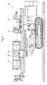
- the drill 1 shown in the drawing is for drilling holes in various surfaces, such as soil, rock or rock. It is a crawler vehicle with a crawler track 2, on the Swivel column 3 via articulated arms 4, a swivel head 5 for the inclination adjustment and a carriage 6 a carriage 7 in all directions is articulated.
- the one that can be raised and lowered as well as all spatial Axle-movable carriage 7 is hydraulically driven by a motor-hydraulic unit 8 driven.
- On the carriage 7 is axially movable in corresponding Guides a drill drive 9 arranged, for example, a Rotary / impact drive or a duplex or double head drive can be.
- the drive head of the drill drive 9 has a threaded connection 10 for the Coupling with the individual shots of the one to be placed or drawn Drill string on.
- Drill rods and / or drill pipes are found as drilling elements 11 Use. As individual shots, these become the drill string composed of the drill drive 9 by turning and / or Beating is driven into the underground, being with the duplex drive Borehole piping and borehole rods rotated and / or simultaneously be beaten.
- a crushing, clamping and Guide device 13 is provided for the drilling elements, which for holding Unscrew and close the threaded connections, the shots of the Drill pipe and the downhole tubing is used.
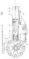
- FIG. 3 of the drawing of the left side of the carriage 7th of the drilling device 1 is a magazine 14 for the drilling elements 11 on the carriage attached, which is designed as a drum magazine.
- Magazine 14 is by means of a drive motor 15 about its central axis 16, which is in the Drilling level 19 is located to the side of the drilling axis 17, rotatable in order the drilling elements in a lying in the drilling plane 19 to the drilling axis 17th to be able to bring the removed removal position.
- the removal itself takes place by means of a handling device 18, which according to FIG Drawing on the opposite, right side of the carriage 7 in the Drilling level 19 is arranged.
- a Drilling element 11 of the magazine fully mechanized and without manual Support can be extracted via a linear movement in the Working position, namely the drilling axis 17, can be spent Drilling element 11 there from the threaded connection 10 of the drilling drive 9 be recorded and by moving towards the front end 12 of the carriage are brought up to already placed drilling elements, there can be connected to the last via a threaded connection then the drilling process itself.
- the Movement of the drill drive 9 with the drilling element 11 takes Handling device 14 management tasks while they are at the Drilling process itself in that shown in Fig. 3 of the drawing The starting position remains, as will be described in more detail below becomes.
- the drilling device 20 shown in FIG. 2 of the drawing differs from the drill 1 described above in that a front rotary drive 21 for outer tubes and a rear rotary drive 22 or hydraulic hammer for an inner linkage is provided and, accordingly, a handling device 23 for the outer tubes and a separate handling device 24 for the inner rods are available to get out of the magazine 14 the handling of the various drilling elements in an optimized manner to be able to perform. It should be noted that in principle can be worked with a handling device 14 at this point could.
- the detailed structure of the handling devices 18, 23 and 24 4, 5, 6 and 7 of the drawing shows the different Operating states, namely the idle state according to FIG. 4 of the drawing Removal state for outer tubes according to FIG. 5 of the drawing and the removal state for inner rods according to FIG. 6 of the drawing. Design details themselves result from the enlarged sectional view of the handling device in Fig. 7, to the following first Reference is made.
- the handling device 18 or 23, 24, from a box-shaped outer housing 25, which is open to the front is to be telescopically displaceable an inner housing 26 arranged therein hold and lead.
- To move the inner housing 26 is one Hydraulic displacement unit 27 is provided, the piston rod 28 on Outer housing 25 is fixed and the cylinder 29 with the bottom of the inner housing 26 is firmly connected, so that the relative movement of this two parts to each other in the event of actuation of the hydraulics in the sense of a Forward or backward displacement of the inner housing 26 affects.
- a rotary bearing 30 for one at the front end of the hydraulic cylinder 29 scissor-like gripper 31, the at least one pivotable about the pivot bearing 30 Upper pliers 32 and lower pliers 33.
- the mouth opening 34 of the The gripper 31 is forward in the direction of movement of the inner housing 26 together with the outer housing 25 a telescopically movable Gripper arm represented with gripper, directed. This will make a linear Forward or backward movement of the handling device in the Drilling level for receiving, positioning, connecting and guiding the Drilling elements for the drilling process and for pulling the drilling elements with the difficult breaking and loosening of the threaded connections fully automatically enables in a simple manner.
- FIG. 7 the Drawing is the closed position. To open the gripper 31 the hydraulic cylinder 40 actuated, the piston rod with the Actuating link 39 is connected.
- the handling device 18 or 23 and 24 is shown in FIGS. 4, 5 and 6 of the drawing with its outer housing 25 slidably on a Guide track 42 of a mounting bracket 43 is arranged, which has a Double-pin joint bearing 44 is attached to the carriage 7.
- the postponement takes place by means of a hydraulic cylinder 45 and is such dimensioned that they complement the extendibility of the telescopic gripper arm the handling device the entire movement path in the drilling plane via the drilling axis 17 to the magazine 14 in the drilling plane 19 and back covered.
- Fig. 4 shows the handling device in its starting position in Idle state with the inner housing 26 retracted and the terminal housing retracted with counter cone 37, 38 and consequently open gripper 31.
- An outer tube is located opposite in the drilling plane Drilling element 11 in removal position in magazine 14.
- FIG. 5 of the drawing shows the handling device 18 in the removal position with the outer casing 25 fully advanced as the position the piston rod of the hydraulic cylinder 45 illustrates, also completely extended inner housing 26, such as the position of the piston rod 28 of the hydraulic cylinder 29 illustrates, and with fully forward in the Closing position of the gripper 31 moved clamp housing with counter cone 37, 38, which also results from the extended piston rod of the Hydraulic cylinder 40 illuminated.
- the gripper 31 detects this Outer tube 11, which is in the removal position of the magazine 14 with the clamping inserts 41 of upper pliers and lower pliers with high Clamping forces and can now be removed by moving the Handling device can be made.
- FIG. 8 Further details on the design of the gripper are Fig. 8 of the drawing removable. From this it follows that the clamping inserts 41 with upper pliers and lower pliers of the gripper 31 screwed and therefore easily replaceable are.
- the spring 46 exerting the restoring force is indicated by dashed lines.
- Fig. 9 of the drawing shows a plan view of the double-pin joint bearing 44, which makes it possible, after pulling a pin B 1 , to pivot the entire fastening bracket 43 with the handling device 18 around the other pin B 2 to the mount 7, so that when not in use to enable narrow transport width by folding in on the side.
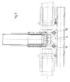
- the drum magazine 14 consists essentially from two at a distance from each other via fastening arms 70 firmly on the Mount 7 of the drill 1 arranged circular disks 50, 51, the left (Circular disc 50) the drive motor 15 and the other centrally (Circular disk 51) a centrally arranged shaft bearing 52 for a intermediate drive shaft 53 carries.
- Each circular disc is 50, 51 on the outer circumference with an inward, welded short sheet metal jacket 54, 55 provided that a loading and removal opening 56 (see FIG. 3) for the drilling elements 11 in the drilling plane 19 on the Has drilling axis 17 facing side.
- a rotatable drum 47 which is formed from two opposite each other, adjacent to the circular discs 50, 51 and within the sheet metal jackets 54, 55 arranged turntables 57, 58, each Corresponding compartments 63 in the outer area for receiving the ends of the Have drilling elements 11.
- the turntables 57, 58 are also provided Hubs 59, 60 firmly connected, which sit on the drive shaft 53 and with these are rotatable.
- the compartments 63 are on the turntables 57, 58 by im essentially semicylindrical welded sheet metal sleeves 64 formed Openings are arranged on the sheet metal side.
- the two rotary plates 57, 58 reinforcing struts arranged in a star shape 61, 62 have.
- the bracket of the Rollers 68 is designed to be radially adjustable by adjusting members 69 Allow adaptation to different drilling element diameters.
- the drum magazine can be modified in accordance with FIGS. 4, 5 and 6 with compartments for receiving drilling elements 11 different Diameter, for example of outer drill pipes (large diameter) and the inner drill rods (smaller Diameter) may be provided.
- the drilling elements 11 are in the drum magazine 14 arranged.
- the loading can depend on what is to be carried out Drilling processes either only drill pipes or only drill pipe or both Drill pipes as well as drill rods, such as according to FIG. 4, 5 and 6.
- a drilling element 11 is through the discharge opening 56, which is also the loading opening, parallel to the carriage 7 in a first compartment 63 of the drum magazine 14 introduced.
- the drum 47 is then turned around an angle of 45 ° for eight compartments and an angle of 22.5 ° for sixteen compartments rotated about their central axis 48 by means of the motor 15, so that the next drilling element can be loaded.
- the first drilling element is removed 11 or the first drill pipe, the handling device 18 from the in Fig. 4 shown position in the removal position shown in FIG. 5 of the Draw the drawing or Fig. 6 of the drawing. That in the removal position located pipe or linkage (generally called drilling element 11) is from Gripper 31 gripped, held and in a linear backward movement in the drilling plane 19 in the drilling position, namely the drilling axis 17, parallel to Carriage 7 of the drill transported.
- the drilling drive 9 is connected to the drilling element 11 moved up to the carriage 7 and the threaded connection 10 with the Drilling element 11 connected.
- the first is first Shot of the inner rod gripped, transported in the drilling axis 17 and after the connection to the drilling drive 9, this is mounted on the carriage 7 retracted far that the movement path for the now following removal the first shot of the outer piping can take place.
- This is according to performed the device shown in Fig. 2 of the drawing by the first operation with the handling device 24 for the inner linkage is carried out and then with the handling device 23 for the outer tube of this is taken from the magazine 14 in an equivalent manner and is transported to the drilling position.
- the inner rod in the outer tube introduced by moving the drill drive 9 and the Threaded connection to the outer tube using a suitable adapter produced.
- the drilling element 11 or the nested Drilling elements 11 are now on the carriage 7 forward to the already in Move the drill string located there and use the Drill drive 9 and the guide device 13 with the already set Drill string firmly connected.
- the handling device As part of the forward movement, the handling device is included open gripper remained in position on the drilling axis 17 to the To guide the drilling element during the forward movement. Then will the handling device in the starting position shown in Fig. 4 retracted and is ready for the next removal process.
- Drilling continues by actuating the rotary and / or impact drive of the drill drive 9 performed.
- the drill drive is then under With the help of the crushing, clamping and guiding device 13 of the now Drilling element 11 already in the borehole is released and attached to the right one End of the carriage 7 moved back to the starting position. Then will in the same way a removal of drilling elements, possibly an inner one Drill pipe and outer drill pipes handled, which are already in the Borehole located pipes screwed on and so successively that Well completed.
- Drilling device deviations in the functional sequence of the Handling device are conceivable without the scope of the invention leave. So sometimes with double pipe systems only parts of the Drilled hole and then the hole is only with the inner Drill pipe continued, resulting in a corresponding adjustment at Drilling and pulling the drilling elements with the handling device leads.
- the described device is suitable for a wide variety of drilling methods customizable, with only minor changes in the Functional sequence or possibly the equipment of the gripper 31 made must be without deviating from the principle of handling.
Abstract
Description
Die Erfindung betrifft ein Bohrgerät zum Bohren von Löchern im Erdreich, Gestein oder Fels, mit einer Lafette, einem an der Lafette verfahrbaren Bohrantrieb für Bohrelemente, wie Bohrrohre und/oder Bohrgestänge, einem parallel zur Lafette angeordneten Trommelmagazin für die Bohrelemente und einer Arretiereinrichtung zur verdrehsicheren Halterung der Bohrelemente in der Arbeitsstellung.The invention relates to a drilling device for drilling holes in the ground, Rock or rock, with a carriage, a drill drive that can be moved on the carriage for drilling elements, such as drill pipes and / or drill rods, one Drum magazine for the drilling elements and arranged parallel to the carriage a locking device for non-rotatable mounting of the drilling elements in the working position.
Bohrgeräte zum Herstellen von Löchern in verschiedenen Untergründen sind bekannt. Sie werden insbesondere gebraucht, um Verpreßanker im Erdreich, Gestein oder Fels zu setzen. Hierzu bestehen die bekannten Bohrgeräte aus einem Raupenfahrzeug, auf dem eine Lafette an Gelenkarmen in allen Richtungen beweglich angelenkt ist. Auf der Lafette ist axial verfahrbar ein Bohrantrieb, Zum Beispiel ein Dreh-/Schlagantrieb, angeordnet, mit dem die einzelnen Bohrelemente gekoppelt werden. Diese werden einem parallel zur Lafette angeordneten Trommelmagazin entnommen. Die Kopplung mit dem Bohrantrieb der Lafette findet gewöhnlich mit Schraubverbindungen statt, über die auch die einzelnen Bohrelemente im Rahmen des Vortriebs des gesamten Bohrstranges miteinander verbunden werden. Nach dem Bohren der Löcher und vor dem Einbringen der Verpreßanker werden die Bohrelemente wieder gezogen und in das Magazin rückgeführt. Dabei stellt die Handhabung der einzelnen Bohrelemente sowohl beim Setzen zur Durchführung des Bohrvorgangs als auch beim Ziehen der Bohrstränge ein außerordentliches Problem dadurch da, daß die einzelnen Bohrelemente in Abhängigkeit von ihrer Länge erhebliche Gewichte besitzen, die am Bohrgerät positioniert, gehalten und verschraubt werden müssen bzw. wieder voneinander gelöst und wegtransportiert werden müssen.Drilling equipment for making holes in various substrates are known. They are used in particular to fix grouting anchors in the ground, To put rock or rock. For this purpose, the known drilling devices consist of a caterpillar on which a carriage on articulated arms in all Directions is articulated. The carriage is axially movable Drill drive, for example a rotary / impact drive, arranged with which the individual drilling elements can be coupled. These are parallel to you Mounted drum magazine removed. The coupling with the Drill drive of the carriage usually takes place with screw connections which also includes the individual drilling elements as part of the advance of the entire Drill string are connected to each other. After drilling the holes and before inserting the grout, the drilling elements are again pulled and returned to the magazine. The handling of the individual drilling elements both when putting to carry out the Drilling process as well as when pulling the drill strings an extraordinary Problem because the individual drilling elements depending on their Length have significant weights that are positioned on the drill and must be screwed or released from each other and have to be transported away.
Bei verschiedenen Bohrverfahren kommt darüber hinaus erschwerend hinzu, daß mit ineinandergesetzten Bohrsträngen gearbeitet wird, zum Beispiel beim Überlagerungsbohren und Doppelkopfbohren, bei dem ein inneres Bohrgestänge mit einem Außenbohrrohr konzentrisch mit Abstand umgeben ist. Für jeden Schuß sind daher zwei unterschiedliche Bohrelemente zu magazinieren, zum Bohrgerät zu transportieren, vorher oder hinterher ineinander anzuordnen, über je zwei Gewindeanschlüsse oben und unten mit dem Bohrantrieb und dem bereits gesetzten Bohrstrang zu verbinden und ist nach Durchführung des Dreh-/Schlag-Bohrvorgangs in umgekehrter Weise das Ziehen der Bohrstränge vorzunehmen.In addition, with various drilling methods, that one works with nested drill strings, for example at Overlay drilling and double head drilling where an internal Surround the drill pipe with an outer drill pipe concentrically at a distance is. Two different drilling elements are therefore required for each shot magazine, transport to the drill, before or after to be arranged in each other, via two threaded connections at the top and bottom with to connect the drill drive and the drill string already set and is after performing the turning / impact drilling process in reverse Pull the drillstrings.
Aus der EP 0 565 502 ist es bekannt, parallel zur Lafette des Bohrgerätes ein
Kastenmagazin für die Bohrelemente anzuordnen und diese aus dem Magazin
heraus maschinell mittels eines verfahrbaren Greifers in die Bohrposition zu
bringen, so daß dort die Kopplung mit dem Bohrantrieb einerseits und dem
bereits im zu bohrenden Loch befindlichen Bohrrohr andererseits
vorgenommen werden kann. Das Magazin weist dabei mehrere Lagerplätze
nebeneinander für verschiedene innere und äußere Rohre auf und erstreckt
sich parallel zu der Lafette des Bohrgerätes, mit der das Magazin fest verbunden
ist. Nachteilig ist, daß die Anordnung der Bohrgestänge in den Bohrrohren
zum Beispiel zum Überlagerungsbohren und Doppelkopfbohren von
Hand noch im Magazin vorgenommen werden muß, bevor der Transport in die
Arbeitsposition mittels des verfahrbaren Greifers vorgenommen werden kann.
Das Einsetzen der Innenstange in das Außenrohr von Hand führt zu einer
Verminderung der zulässigen Rohrelemente-Länge dadurch, daß gesetzlich nur
noch 25 kg von Hand gehoben werden dürfen, so daß nur noch Bohrelemente
von 1 m bis 1,5 m Länge angewendet werden können. Dies bedingt bei einer
vorgegebenen Bohrlochlänge eine erhebliche Erhöhung der Zahl der zu
schaffenden und wieder zu lösenden Verbindungen, so daß ein enormer
Zeitverlust und auch Verschleiß an den Verbindungsgewinden durch das
häufige An- und Abschrauben entsteht. From EP 0 565 502 it is known to parallel to the mount of the drill
Arrange box magazine for the drilling elements and these from the magazine
out mechanically into the drilling position using a movable gripper
bring so that there the coupling with the drill drive on the one hand and the
On the other hand, the drill pipe already in the hole to be drilled
can be made. The magazine has several storage locations
side by side for different inner and outer pipes and stretches
parallel to the carriage mount with which the magazine is firmly connected
is. It is disadvantageous that the arrangement of the drill rods in the drill pipes
for example for overlay drilling and double-head drilling from
Hand must still be made in the magazine before transport to the
Working position can be made by means of the movable gripper.
Inserting the inner rod into the outer tube by hand leads to one
Reduction of the permissible pipe element length by the fact that only by
Ferner ist nachteilig, daß beim Ziehen das Innengestänge zunächst separat gelagert werden muß, bis dann die Außenrohre gezogen sind, diese im Kastenmagazin untergebracht worden sind, so daß dann anschließend wiederum in einem eigenständigen Arbeitsvorgang die Innengestänge in die Außenrohre im Magazin eingebracht werden müssen, um das Magazin bereit für einen neuen Bohrvorgang zu haben.Another disadvantage is that when pulling the inner linkage initially separately must be stored until the outer tubes are pulled, these in Box magazine have been accommodated, so that then again in turn the inner rods into the outer tubes in a separate process must be placed in the magazine to make the magazine ready for to have a new drilling operation.
In Verbindung mit dem bekannten Kastenmagazin wird eine Handhabungsvorrichtung benutzt, die aus einem am Magazin angebrachten, vertikal emporragenden teleskopartig ein- und ausfahrbaren Pfosten besteht, an dem kragartig ein Greiferbaum befestigt ist, welcher ebenfalls teleskopartig ausfahrbar ist und sowohl den Magazinbereich als auch den Arbeitsbereich der Lafette des Bohrgerätes überfahren kann. Am äußeren, ausziehbaren Teil des Greiferbaums ist eine Greifklaue vorgesehen, die im Zusammenwirken mit einem Widerlager ausgelegt ist, ein Bohrrohr aus dem Magazin herauszugreifen und festzuhalten sowie über die Betätigung des teleskopisch ausfahrbaren Pfostens und Greiferbaums in die Bohrposition an der Lafette des Bohrgerätes zu verbringen.In connection with the known box magazine is a handling device used that from a vertically towering attached to the magazine telescopic retractable and extendable post exists on the a claw tree is attached in a collar-like manner, which can also be extended telescopically and both the magazine area and the work area of the Can run over the gun carriage. On the outer, extendable part of the A gripper claw is provided in cooperation with an abutment is designed to pull a drill pipe out of the magazine and to hold on and to operate the telescopically extendable Post and gripper tree in the drilling position on the mount of the drill to spend.
Für die Handhabung von inneren Bohrgestängen ist ein separater scherenförmiger Greifer vorgesehen.A separate scissor-shaped one is used for handling inner drill rods Gripper provided.
Nachteilig ist bei dieser aus der EP 0 565 502 bekannten Handhabungsvorrichtung, daß sie als integrierter Bestandteil des Magazins für die Bohrelemente ausgelegt ist und daher einseitig eine erhebliche Schwerpunktsverlagerung neben der Lafette des Bohrgerätes erzeugt, die zwecks Erhaltung der Standsicherheit und Verfahrbarkeit des Bohrgerätes mit anderen, zusätzlichen Mitteln ausgeglichen werden muß. Die Handhabungsvorrichtung ist technisch aufwendig, schwer und führt komplexe Bewegungsvorgänge durch die in verschiedenen Ebenen und rechtwinklig zueinander angeordneten Teleskopelemente durch. Dabei führt der frei über den gesamten Bewegungsweg vorkragende Greiferbaum zu Stabilitätsproblemen, da an dessen freien Ende mit langem Hebelarm die Last angeordnet ist und mit dieser lange Verfahr- und Transportwege bewältigt werden müssen. Nachteilig ist darüber hinaus, daß der Greifer nicht zur Unterstützung des Lösens der Schraubverbindungen vorgesehen ist und auch eine zu geringe Klemmwirkung hat, um die einzelnen Bohrelementen sicher ohne manuelle Hilfe vom Bohrantrieb zu lösen.A disadvantage of this handling device known from EP 0 565 502 is that they are an integral part of the magazine for the drilling elements is designed and therefore one-sided a significant shift in focus in addition to the mount of the drill, which is used for conservation the stability and movability of the drilling rig with other, additional Funds must be balanced. The handling device is technically complex, heavy and carries out complex movements which are arranged in different levels and at right angles to each other Telescopic elements through. It leads freely over the entire path of movement cantilevered grab tree to stability problems, because of its free End with a long lever arm the load is arranged and with this long travel and transport routes must be mastered. The disadvantage is that in addition, that the gripper does not support the loosening of the screw connections is provided and also has too little clamping effect to the individual drilling elements safely without manual help from the drilling drive to solve.
Aus der DE-A 41 26 919 ist ein Bohrgerät mit einem Magazin für Bohrelemente bekannt, bei dem das Magazin trommelförmig und um seine Mittelachse rotierbar ausgebildet ist. Derart kann das Magazin über den Umfang verteilt mehrere Schüsse aufnehmen, die nach außen entnehmbar sind. Um den Transport in die Bohrposition an der Lafette des Bohrgerätes zu bewerkstelligen, ist das Magazin aus einer außenliegenden Vorratslage über einen Schwenkantrieb um eine Schwenkachse nach einwärts in die Arbeitsstellung schwenkbar, in der der Bohrantrieb der Lafette des Bohrgerätes den fluchtenden, zugeordneten Schuß des Bohrgestänges aufnehmen kann. Nach der Übernahme des zugeordneten Schusses schwenkt das Magazin wieder in die Vorratslage zurück.DE-A 41 26 919 discloses a drilling device with a magazine for drilling elements known, in which the magazine is drum-shaped and about its central axis is rotatable. So the magazine can cover the scope take several shots distributed, which are removable from the outside. Around carry out the transport to the drilling position on the mount of the drilling rig, is the magazine from an external supply layer above one Swivel drive around a swivel axis inwards into the working position pivotable, in which the drill drive of the carriage of the drill aligned, assigned shot of the drill pipe can take. After the magazine swings in again when the assigned shot is taken over the stock level back.
Nachteilig ist bei dem bekannten Trommelmagazin, daß mit getrennten Trommeln für Bohrgestänge und Bohrrohre gearbeitet werden muß, so daß mehrere Magazine in Längsrichtung hintereinander an der Lafette, ggf. sogar beidseitig, angeordnet werden müssen. Durch die Hintereinanderanordnung stellt sich nachteiligerweise eine außerordentlich große Länge des Bohrgerätes ein. Wegen der erforderlichen Verschwenkbarkeit der Trommelmagazine aus der außenliegenden Vorratslage in die Arbeitslage, d.h. in die Bohrachse, ist ein Schwenkantrieb erforderlich und muß ein aufwendiger und positionspräziser Schwenkmechanismus vorgesehen werden, der beschädigungsanfällig ist und im Funktionsablauf wegen der großen zu bewegenden Massen langsam ist. Für die Beschickung des Bohrgeräts mit jedem einzelnen Bohrelement muß das gesamte Magazin mit seinem hohen Gewicht hin- und zurückgeschwenkt werden.A disadvantage of the known drum magazine is that with separate Drums for drill pipes and drill pipes must be worked so that several magazines in the longitudinal direction one behind the other on the carriage, possibly even must be arranged on both sides. Through the arrangement in a row disadvantageously arises an extraordinarily large length of the drilling device a. Because of the required pivotability of the drum magazines the external supply position into the working position, i.e. in the drilling axis a swivel drive is required and must be an elaborate and positionally precise Swivel mechanism are provided, which is prone to damage is and in the functional sequence because of the large masses to be moved is slow. For loading the drilling rig with every single drilling element the entire magazine with its heavy weight has to go back and forth be pivoted back.
Um das Verbinden des Bohrantriebs mit dem in Arbeitsstellung befindlichen Schuß des Bohrgestänges funktionssicher durchführen zu können, besitzt das bekannte Trommelmagazin eine Arretiervorrichtung, die vorgesehen ist, den in Arbeitsstellung befindlichen Schuß des Bohrgestänges verdrehsicher zu halten, so daß der Bohrantrieb mit diesem Schuß durch Verschraubung verbunden werden kann. Die Arretiervorrichtung stellt jedoch keine Handhabungsvorrichtung dar, sondern bewirkt nur, daß das jeweilige Bohrelement in der Arbeitsstellung sich nicht verdreht, wenn der Bohrantrieb mit dem oberen Ende des Bohrelementes verschraubt wird.To connect the drill drive with the one in the working position To be able to perform a shot of the drill pipe functionally reliable known drum magazine has a locking device which is provided in To keep the shot of the drill pipe in the working position against rotation, so that the drill drive is connected to this shot by screwing can be. However, the locking device is not a handling device represents, but only causes that the respective drilling element in the Working position does not twist when the drill drive with the upper one End of the drilling element is screwed.
Der Erfindung liegt in Anbetracht dieses Standes der Technik die Aufgabe zugrunde, unter Meidung der obengenannten Nachteile ein kurz bauendes Bohrgerät der eingangs genannten Art zu entwickeln, bei dem Bohrelemente aller Art, insbesondere für Überlagerungs- und Doppelkopfbohren, in einem einzigen Magazin gelagert werden können und aus diesem ohne manuellen Zugriff vollkommen maschinell ohne Verschwenkung des Magazins der Arbeitsstellung zugeführt werden können bzw. nach dem Ziehen der Bohrelemente wieder rückgeführt werden können, wobei auch das Ineinandersetzen von Bohrelementen maschinell durchführbar sein soll.In view of this prior art, the invention is based on the task , while avoiding the disadvantages mentioned above, of developing a short-sized drilling rig of the type mentioned at the outset, in which drilling elements of all kinds, in particular for overlay and double-head drilling, can be stored in a single magazine and from this, without manual access, can be fed completely mechanically to the working position without pivoting the magazine or can be returned again after the drilling elements have been pulled, the interlocking of drilling elements should also be able to be carried out mechanically.
Die Aufgabe ist erfindungsgemäß dadurch gelöst, daß ein fest, unverschwenkbar an der Lafette angeordnetes Trommelmagazin mit drehbarer Trommel kombiniert wird mit einer quer zu der Lafette und dem Trommelmagazin arbeitenden Handhabungsvorrichtung, die einen teleskopartig verfahrbaren Greifarm mit einem Greifer aufweist, dessen Maulöffnung in Bewegungsrichtung des Greifarms axial nach vorn gerichtet angeordnet ist. Hierdurch wird in vorteilhafter Weise erreicht, daß mit einem kurzbauenden Bohrgerät für jedes Bohrverfahren ein nach der Erstbeladung in vollem Umfang maschinelles Erfassen, Transportieren, Positionieren und Verbinden der Bohrelemente in der Bohrebene mit dem Bohrantrieb sowie Ziehen der Bohrelemente und Rückführen in das Magazin ermöglicht ist. wobei sowohl das Trommelmagazin als auch die Handhabungsvorrichtung konstruktiv gegenüber den bisher bekannten Einrichtungen sehr kompakt, leicht und einfach aufgebaut werden können und nur eine einfache lineare Bewegung im Wege des Transports in der Bohrebene durchgeführt werden muß.The object is achieved in that a fixed, non-pivotable drum magazine arranged on the carriage with rotatable The drum is combined with one across the carriage and the Drum magazine working handling device that telescopically has movable gripper arm with a gripper, the jaw opening in Direction of movement of the gripper arm is arranged axially forward. This is advantageously achieved with a short construction Drill rig for each drilling process in full after initial loading mechanical detection, transport, positioning and connection of the Drilling elements in the drilling plane with the drill drive and pulling the Drilling elements and return to the magazine is made possible. being both the drum magazine and the handling device constructively compared to the previously known devices very compact, light and can be built easily and just a simple linear movement in the Ways of transportation in the drilling plane must be carried out.
Vorzugsweise ist das Trommelmagazin mit seiner Mittel- und Rotationsachse in der Bohrebene seitlich der Bohrachse angeordnet und ist seine Belade- und Entnahmeöffnung zur Bohrachse hin gewendet, wobei die Handhabungsvorrichtung auf der gegenüberliegenden Seite der Lafette in der Bohrebene derart angeordnet ist, daß in einer Linearbewegung der Greifer in der Bohrebene über die Lafette zur Belade- und Entnahmeöffnung des Trommelmagazins vorfahrbar und rückfahrbar ist. Hierdurch wird eine lineare Vorwärts-und Rückwärtsbewegung der Handhabungsvorrichtung in der Bohrebene zum Aufnehmen der Bohrelemente aus dem Trommelmagazin heraus, Positionieren und Arretieren in der Bohrachse, Verbinden mit dem Bohrantrieb sowie Führen der Bohrelemente während des Verfahrens zum Bohrstrang zum Zwecke der Verbindung mit diesem und anschließend das Ziehen der Bohrelemente mit dem schwierigen Brechen und Lösen der Gewindeverbindungen vollmaschinell in einfacher Weise ermöglicht. Zweckmäßigerweise besteht dazu der Greifer aus einer um ein zentrales in der Bohrebene angeordnetes Drehlager beweglichen Oberzange und Unterzange, die mit je einer Außenkonusfläche versehen sind, an der je ein Klemmgehäuse mit Gegenkonus axial, vorzugsweise mit einem Hydraulikzylinder verschiebbar für den Schließvorgang angeordnet ist und die in Richtung Öffnung federbelastet sind. Hierdurch können überraschend hohe Klemmkräfte am Bohrelement durch die vorhandenen formschlüssigen Verbindungen der Greifelemente bei einfacher und robuster Mechanik ausgeübt werden. Dabei kann es zweckmäßig sein, die Arbeitsflächen des Greifers mit Klemmeinsätzen zu bestücken, die leicht auswechselbar sind und daher die Betriebsbereitschaft der Handhabungsvorrichtung über eine lange Lebensdauer sicherstellen.The drum magazine is preferably with its central and rotational axis arranged in the drilling plane to the side of the drilling axis and is its loading and Removal opening turned towards the drilling axis, the handling device on the opposite side of the carriage in the drilling plane is arranged such that in a linear movement the gripper in the drilling plane over the carriage to the loading and unloading opening of the drum magazine is retractable and retractable. This will make a linear forward and Backward movement of the handling device in the drilling plane to Picking up the drilling elements from the drum magazine, positioning and locking in the drilling axis, connecting to the drill drive and guiding of drilling elements during the process of drilling string for the purpose of Connect with this and then pull the drilling elements with the difficult breaking and loosening of the threaded connections fully automatically enables in a simple manner. The gripper is expediently provided for this purpose from a pivot bearing arranged around a central one in the drilling plane movable top and bottom pliers, each with an outer cone surface are provided, on each of which a clamp housing with a counter cone axially, preferably slidable with a hydraulic cylinder for the Closing process is arranged and which are spring-loaded in the direction of the opening. This can surprisingly high clamping forces on the drilling element by the existing positive connections of the gripping elements with simple and robust mechanics. It may be appropriate to Work surfaces of the gripper can be equipped with clamping inserts that are easy are interchangeable and therefore the operational readiness of the handling device ensure over a long service life.
Der teleskopartig verfahrbare Greifarm der Handhabungsvorrichtung des erfindungsgemäßen Bohrgerätes besteht vorteilhafterweise aus einem in einem Außengehäuse durch eine hydraulische Verschiebeeinheit teleskopartig aus- und einfahrbaren Innengehäuse, wobei an dem freien vorderen Ende des Verschiebezylinders der Greifer angelenkt ist und zwischen dem Greifer und dem Innengehäuse in gegenüberliegender Anordnung das Klemmgehäuse mit Gegenkonus axial über eine Betätigungskulisse mit daran angeschlossenem Hydraulikzylinder verschiebbar angeordnet sind. Mit dieser kompakten Anordnung wird eine außerordentlich hohe Festigkeit und Leistungsfähigkeit erreicht, so daß Bohrelemente von 120 kg und mehr Gewicht leicht handhabbar und in ihrer Position von der Handhabungsvorrichtung fixierbar sind.The telescopically movable gripper arm of the handling device of the invention Drilling device advantageously consists of one in one Outer housing telescopic like a hydraulic displacement unit retractable inner housing, being at the free front end of the Shift cylinder of the gripper is articulated and between the gripper and the inner housing in an opposite arrangement with the terminal housing Counter cone axially via an actuating link with attached Hydraulic cylinders are slidably arranged. With this compact Arrangement is extremely high strength and performance achieved so that drilling elements of 120 kg and more weight easily manageable and fixable in position by the handling device are.
Um die Handhabungsvorrichtung an die verschiedenen Gegebenheiten unterschiedlicher Bohrgeräte anpassen zu können, ist gemäß einer weiteren Ausgestaltung der Erfindung vorgesehen, das Außengehäuse auf einer Führungsbahn der Befestigungskonsole mittels eines Hydraulikzylinders in der Bohrebene axial verfahrbar zu lagern, so daß auch größere Verfahrstrecken bei gleichbleibend kleinen Längenabmessungen der Handhabungsvorrichtung und gleichbleibender Teleskop-Verfahrstrecke des Greifarms bewältigt werden können.To make the handling device different to the different circumstances According to a further embodiment, being able to adapt drilling devices provided the invention, the outer housing on a track the mounting bracket using a hydraulic cylinder in the drilling plane axially movable to store, so that even larger travel distances consistently small length dimensions of the handling device and constant telescopic travel distance of the gripper arm can be mastered can.
Darüber hinaus kann vorgesehen sein, die Befestigungskonsole mit der Handhabungsvorrichtung verschwenkbar an der Lafette anzuordnen, um bei Nichtgebrauch einen geringere Transportbreite durch Einklappen seitlich an die Lafette des Bohrgerätes sicherzustellen. Vorzugsweise wird hierbei eine Doppel-Bolzen-Gelenklagerung verwendet.In addition, it can be provided the fastening bracket with the handling device can be pivoted on the carriage to be arranged when not in use a smaller transport width by folding in on the side Ensure the carriage of the drill rig. This is preferably a Double-pin joint bearing used.
Gemäß der bevorzugten Ausgestaltung des erfindungsgemäßen Bohrgerätes ist die Handhabungsvorrichtung kombiniert mit einem Trommelmagazin, welches aus zwei mit Abstand zueinander fest an der Lafette des Bohrgeräts angeordneten Kreisscheiben besteht, deren eine zentrisch einen Antriebsmotor und deren andere eine zentrisch angeordnete Wellenlagerung für eine dazwischen angeordnete Antriebswelle trägt, wobei jede Kreisscheibe mit einem nach innen gerichteten Blechmantel versehen ist, der eine Belade- und Entnahmeöffnung für die Bohrelemente in der Bohrebene auf der zur Bohrachse hingewandten Seite aufweist, und wobei mit der Antriebswelle sowohl motorseitig als auch lagerungsseitig je ein parallel zur benachbarten Kreisscheibe angeordneter Drehteller verbunden ist, der innerhalb des Blechmantels drehbar ist und jeweils im in radialer Richtung äußeren Bereich nach innen gerichtete korrespondierende Fächer zur Aufnahme der Enden von Bohrelementen aufweist. Die Fächer sind an den Drehtellern zweckmäßigerweise durch im wesentlichen halbzylindrische aufgeschweißte Blechmuffen gebildet, deren Öffnungen blechmantelseitig angeordnet sind. Die Blechmuffen können zur Verbesserung der Führung für die Bohrelemente über den Mantel nach innen vorstehen.According to the preferred embodiment of the drilling device according to the invention is the handling device combined with a drum magazine, which consists of two spaced from each other firmly on the mount of the drill arranged circular disks, one of which is centrally a drive motor and the other a centrally arranged shaft bearing for one intermediate drive shaft carries, each circular disc with an inward facing sheet metal jacket is provided, the loading and Removal opening for the drilling elements in the drilling plane on the Has drilling axis facing side, and being with the drive shaft both on the motor side and on the bearing side, one parallel to the neighboring one Circular disc arranged turntable is connected within the Sheet metal jacket is rotatable and in each case in the outer area in the radial direction corresponding inward-facing compartments for receiving the ends of Has drilling elements. The compartments are on the turntables expediently by essentially semi-cylindrical welded Sheet metal sleeves are formed, the openings of which are arranged on the sheet metal jacket side. The Sheet metal sockets can be used to improve the guidance for the drilling elements project the coat inside.
Ebenfalls zur Verbesserung der Führung und Halterung dienen zwei in der bevorzugten Ausführungsform mit Abstand zur Mitte vorgesehene, auf der Welle befestigte scheibenförmige Rohrhalter mit am äußeren Umfang vorgesehenen U-förmigen Ausnehmungen für die Bohrelemente und zwischen den Ausnehmungen angeordneten Rollen- oder Elastomer-Elementen, die an den eingesetzten Bohrelementen außen anlegen und diese sichern. Die Halterung für die Rollen- oder Elastomer-Elemente kann radial verstellbar sein, um eine Anpassung an unterschiedliche Bohrelemente-Durchmesser zu ermöglichen.Also serve to improve the leadership and bracket two in the preferred embodiment provided at a distance from the center, on the Shaft-attached disc-shaped tube holder with provided on the outer circumference U-shaped recesses for the drilling elements and between the Recesses arranged roller or elastomer elements on the Place the drilling elements used on the outside and secure them. The bracket for the roller or elastomer elements can be radially adjustable to a Allow adaptation to different drilling element diameters.
Das Trommelmagazin kann mit Fächern zur Aufnahme von Bohrelementen unterschiedlicher Durchmesser, beispielsweise äußeren Bohrrohren und jeweils dazwischen angeordneten inneren Bohrgestängen vorgesehen sein. Bei dieser, insbesondere für das Überlagerungs- und Doppelkopfbohren verwendeten Ausführung eines Trommelmagazins ist es vorteilhaft, das erfindungsgemäße Bohrgerät mit einer Doppelgreiferanordnung an der Handhabungsvorrichtung oder zwei nebeneinander angeordneten Handhabungsvorrichtungen mit Greifern vorzusehen, die zum einen für die Handhabung der Bohrelemente größeren Durchmessers und zum anderen für die Handhabung der Bohrelemente kleineren Durchmessers vorgesehen sind.The drum magazine can be equipped with compartments to hold drilling elements different diameters, for example outer drill pipes and each arranged in between inner drill rods. At this, used especially for overlay and double-head drilling Execution of a drum magazine, it is advantageous to the invention Drill with a double gripper arrangement on the handling device or two handling devices arranged side by side with To provide grippers, on the one hand for handling the drilling elements larger diameter and secondly for handling the drilling elements smaller diameter are provided.
Weitere Einzelheiten, Merkmale und Vorteile des Gegenstandes der Erfindung ergeben sich aus der nachfolgenden Beschreibung der zugehörigen Zeichnung, in der ein erfindungsgemäßes Bohrgerät schematisch dargestellt ist. In der Zeichnung zeigt:
- Fig. 1
- Eine Seitenansicht eines Bohrgerätes, insbesondere zum Rammbohren, schematisch;
- Fig. 2
- eine Seitenansicht eines Bohrgerätes, insbesondere zum Doppelkopfbohren, schematisch;
- Fig. 3
- das Bohrgerät der Fig. 1 in Seitenansicht mit um 90° verdrehter Lafette;
- Fig. 4
- eine vergrößerte Seitenansicht eines Trommelmagazins mit einer Handhabungsvorrichtung als Teil eines Bohrgerätes in der Lafettenstellung entsprechend Fig. 2 der Zeichnung für Doppelkopfbohren;
- Fig. 5
- eine Darstellung entsprechend Fig. 4 mit der Handhabungsvorrichtung in Entnahmeposition am Magazin für Außenrohre;
- Fig. 6
- eine Darstellung entsprechend Fig. 5 in der Entnahmeposition für Innengestänge;
- Fig. 7
- die Handhabungsvorrichtung in Schnittdarstellung;
- Fig. 8
- einen Greifer der Handhabungsvorrichtung;
- Fig. 9
- eine Draufsicht auf eine Doppel-Bolzen-Gelenklagerung der Handhabungsvorrichtung an der Lafette des Bohrgerätes und
- Fig. 10
- ein Trommelmagazin in Seitenschnittansicht mit wesentlichen Teilen darüber in Draufsicht.
- Fig. 1
- A side view of a drill, especially for ramming, schematically;
- Fig. 2
- a side view of a drilling device, in particular for double-head drilling, schematically;
- Fig. 3
- 1 in a side view with the mount rotated by 90 °;
- Fig. 4
- an enlarged side view of a drum magazine with a handling device as part of a drill in the mount position according to Figure 2 of the drawing for double-head drilling.
- Fig. 5
- a representation corresponding to Figure 4 with the handling device in the removal position on the magazine for outer tubes.
- Fig. 6
- a representation corresponding to Figure 5 in the removal position for inner rods.
- Fig. 7
- the handling device in a sectional view;
- Fig. 8
- a gripper of the handling device;
- Fig. 9
- a plan view of a double-pin joint bearing of the handling device on the carriage of the drill and
- Fig. 10
- a drum magazine in side sectional view with essential parts above it in plan view.
Das in der Zeichnung dargestellte Bohrgerät 1 ist zum Bohren von Löchern in
verschiedenen Untergründen, wie Erdreich, Gestein oder Fels, vorgesehen. Es
handelt sich um ein Raupenfahrzeug mit einem Raupenfahrwerk 2, an dessen
Schwenksäule 3 über Gelenkarme 4, einen Schwenkkopf 5 für die Neigungseinstellung
und einen Lafettenträger 6 eine Lafette 7 in allen Richtungen
beweglich angelenkt ist. Die heb- und senkbare sowie nach allen räumlichen
Achsrichtungen bewegbare Lafette 7 wird hydraulisch von einer Motor-Hydraulik-Einheit
8 angetrieben. Auf der Lafette 7 ist axial verfahrbar in entsprechenden
Führungen ein Bohrantrieb 9 angeordnet, der zum Beispiel ein
Dreh-/Schlagantrieb oder ein Duplex- oder Doppelkopfantrieb sein kann. Dabei
weist der Antriebskopf des Bohrantriebes 9 einen Gewindeanschluß 10 für die
Kopplung mit den einzelnen Schüssen des zu setzenden oder zu ziehenden
Bohrstranges auf. Als Bohrelemente 11 finden Bohrgestänge und/oder Bohrrohre
Verwendung. Diese werden als einzelne Schüsse zum Bohrstrang
zusammengesetzt, der von dem Bohrantrieb 9 durch Drehen und/oder
Schlagen in den Untergrund eingetrieben wird, wobei beim Duplex-Antrieb
Bohrlochverrohrung und Bohrlochgestänge gleichzeitig gedreht und/oder
geschlagen werden.The
Im in der Zeichnung vorderen Ende 12 der Lafette 7 ist eine Brech-, Klemm- und
Führungseinrichtung 13 für die Bohrelemente vorgesehen, die zum Festhalten,
Aufdrehen und Zudrehen der Gewindeverbindungen, der Schüsse des
Bohrgestänges und der Bohrlochverrohrung dient. In the
Auf der einen Seite, gemäß Fig. 3 der Zeichnung der linken Seite der Lafette 7
des Bohrgerätes 1, ist ein Magazin 14 für die Bohrelemente 11 an der Lafette
befestigt, das als Trommelmagazin ausgebildet ist. Der detaillierte Aufbau des
Trommelmagazins 14 ergibt sich aus Fig. 10 der Zeichnung. Das Magazin 14
ist mittels eines Antriebsmotors 15 um seine Mittelachse 16, die sich in der
Bohrebene 19 seitlich der Bohrachse 17 befindet, rotierbar, um nacheinander
die Bohrelemente in eine in der Bohrebene 19 liegende, zur Bohrachse 17
hingewendete Entnahmeposition bringen zu können. Die Entnahme selbst
findet mittels einer Handhabungsvorrichtung 18 statt, die gemäß Fig. 3 der
Zeichnung auf der gegenüberliegenden, rechten Seite der Lafette 7 in der
Bohrebene 19 angeordnet ist. Mit der Handhabungsvorrichtung 18 kann ein
Bohrelement 11 dem Magazin vollmechanisiert und ohne manuelle
Unterstützung entnommen werden, über eine lineare Bewegung in die
Arbeitsposition, nämlich die Bohrachse 17, verbracht werden, kann das
Bohrelement 11 dort von dem Gewindeanschluß 10 des Bohrantriebs 9
aufgenommen werden und durch Verfahren in Richtung auf das vordere Ende
12 der Lafette an bereits gesetzte Bohrelemente herangebracht werden, dort
über einen Gewindeanschluß mit dem letzten verbunden werden und kann
anschließend der Bohrvorgang selbst durchgeführt werden. Während des
Verfahrens des Bohrantriebs 9 mit dem Bohrelement 11 nimmt die
Handhabungsvorrichtung 14 Führungsaufgaben wahr, während sie bei dem
Bohrvorgang selbst in der in Fig. 3 der Zeichnung dargestellten
Ausgangsposition verbleibt, wie weiter unten noch näher beschrieben werden
wird.On the one hand, as shown in FIG. 3 of the drawing of the left side of the carriage 7th
of the
Das in Fig. 2 der Zeichnung dargestellte Bohrgerät 20 unterscheidet sich von
dem oben beschriebenen Bohrgerät 1 dadurch, daß ein vorderer Drehantrieb
21 für Außenrohre und ein hinterer Drehantrieb 22 oder Hydraulikhammer für
ein Innengestänge vorgesehen sind und dementsprechend auch eine Handhabungsvorrichtung
23 für die Außenrohre und eine separate Handhabungsvorrichtung
24 für das Innengestänge vorhanden sind, um aus dem Magazin
14 heraus in optimierter Weise die Handhabung der verschiedenen Bohrelemente
durchführen zu können. Es sei angemerkt, daß grundsätzlich auch
mit einer Handhabungsvorrichtung 14 an dieser Stelle gearbeitet werden
könnte. Der detaillierte Aufbau der Handhabungsvorrichtungen 18, 23 und 24
ergibt sich aus den Fig. 4, 5, 6 und 7 der Zeichnung, die unterschiedliche
Betriebszustände, nämlich den Ruhezustand gemäß Fig. 4 der Zeichnung, den
Entnahmezustand für Außenrohre gemäß Fig. 5 der Zeichnung und den Entnahmezustand
für Innengestänge gemäß Fig. 6 der Zeichnung zeigen.
Konstruktive Details selbst ergeben sich aus der vergrößerten Schnittdarstellung
der Handhabungsvorrichtung in Fig. 7, auf die nachfolgend zunächst
Bezug genommen wird.The
Gemäß Fig. 7 der Zeichnung besteht die Handhabungsvorrichtung 18 bzw.
23, 24, aus einem kastenförmigen Außengehäuse 25, das nach vorne offen
ist, um teleskopartig verschiebbar ein darin angeordnetes Innengehäuse 26 zu
halten und zu führen. Zur Verschiebung des Innengehäuses 26 ist eine
Hydraulik-Verschiebeeinheit 27 vorgesehen, deren Kolbenstange 28 am
Außengehäuse 25 fixiert ist und deren Zylinder 29 mit dem Boden des Innengehäuses
26 fest verbunden ist, so daß sich die Relativbewegung dieser
beiden Teile zueinander im Falle einer Betätigung der Hydraulik im Sinne einer
Vorwärts- oder Rückwärtsverschiebung des Innengehäuses 26 auswirkt. Am
vorderen Ende des Hydraulikzylinders 29 findet sich ein Drehlager 30 für einen
scherenartigen Greifer 31, der mindestens eine um das Drehlager 30 verschwenkbare
Oberzange 32 und Unterzange 33 aufweist. Im beschriebenen
Ausführungsbeispiel sind Doppelzangen vorgesehen. Die Maulöffnung 34 des
Greifers 31 ist nach vorn in Bewegungsrichtung des Innengehäuses 26, das
gemeinsam mit dem Außengehäuse 25 einen teleskopartig verfahrbaren
Greifarm mit Greifer repräsentiert, gerichtet. Hierdurch wird eine lineare
Vorwärts- oder Rückwärtsbewegung der Handhabungsvorrichtung in der
Bohrebene zum Aufnehmen, Positionieren, Verbinden und Führen der
Bohrelemente für den Bohrvorgang sowie für das Ziehen der Bohrelemente mit
dem schwierigen Brechen und Lösen der Gewindeverbindungen vollmaschinell
in einfacher Weise ermöglicht.7 of the drawing, the handling
Eine besonders hohe Klemmwirkung des Greifers 31 wird erreicht, indem
Oberzange 32 und Unterzange 33 mit je einer Außenkonusfläche 35, 36 versehen
sind, an der ein Klemmgehäuse mit Gegenkonus 37, 38 formschlüssig
zum Innengehäuse 26 angeordnet ist. Das Klemmgehäuse mit Gegenkonus
37, 38 ist über eine dahinter angeordnete und mit ihm verschweißte
Betätigungskulisse 39 mittels eines Hydraulikzylinders 40 axial verschiebbar,
wodurch sich über die Außenkonusflächen 35, 36 und das Klemmgehäuse mit
Gegenkonus 37, 38 die Oberzangen 32 und Unterzangen 33 durch eine
gegeneinander gerichtete Bewegung öffnen und schließen lassen. In Fig. 7 der
Zeichnung ist die Schließstellung darstellt. Zum Öffnen des Greifers 31 wird
der Hydraulikzylinder 40 betätigt, dessen Kolbenstange mit der
Betätigungskulisse 39 verbunden ist. Mit dem Zurückziehen der
Betätigungskulisse 39 nach hinten werden entsprechend der Konusausgestaltung
die Schließkräfte sukzessive zurückgenommen und können sich die
Oberzangen 32 und Unterzangen 33 dadurch öffnen, daß eine in der Fig. 7
der Zeichnung nicht dargestellte Federbelastung in Öffnungsrichtung wirksam
wird. Umgekehrt erzeugt eine Bewegung der Kolbenstange des Hydraulikzylinders
40 nach vorn über die Betätigungskulisse 39 über die Konusausgestaltung
37, 38 außerordentlich hohe Schließ- und Haltekräfte in der in Fig.
7 der Zeichnung dargestellten Schließstellung des Greifers 31. Die
Arbeitsflächen des Greifers 31 sind mit Klemmeinsätzen 41 aus gehärtetem
Material bestückt, die leicht auswechselbar sind und die Betriebsbereitschaft
der Handhabungsvorrichtung über eine lange Lebensdauer sichern.A particularly high clamping effect of the
Die Handhabungsvorrichtung 18 bzw. 23 und 24 ist gemäß den Fig. 4, 5 und
6 der Zeichnung mit ihrem Außengehäuse 25 verschiebbar auf einer
Führungsbahn 42 einer Befestigungskonsole 43 angeordnet, die über eine
Doppel-Bolzen-Gelenklagerung 44 an der Lafette 7 befestigt ist. Die Verschiebung
findet mittels eines Hydraulikzylinders 45 statt und ist derart
bemessen, daß sie in Ergänzung zu der Ausfahrbarkeit des Teleskop-Greifarms
der Handhabungsvorrichtung den gesamten Bewegungsweg in der Bohrebene
über die Bohrachse 17 zum Magazin 14 in der Bohrebene 19 und zurück
überdeckt.The handling
Fig. 4 zeigt dabei die Handhabungsvorrichtung in ihrer Ausgangsposition im
Ruhezustand mit eingefahrenem Innengehäuse 26 und eingefahrenem Klemmgehäuse
mit Gegenkonus 37, 38 und folglich geöffnetem Greifer 31.
Gegenüberliegend in der Bohrebene befindet sich ein Außenrohr als
Bohrelement 11 in Entnahmeposition im Magazin 14.Fig. 4 shows the handling device in its starting position in
Idle state with the
Fig. 5 der Zeichnung zeigt die Handhabungsvorrichtung 18 in Entnahmeposition
mit vollständig vorgefahrenem Außengehäuse 25, wie die Stellung
der Kolbenstange des Hydraulikzylinders 45 verdeutlicht, mit ebenfalls vollständig
ausgefahrenem Innengehäuse 26, wie die Stellung der Kolbenstange
28 des Hydraulikzylinders 29 verdeutlicht, und mit vollständig nach vorn in die
Schließposition des Greifers 31 verfahrenem Klemmgehäuse mit Gegenkonus
37, 38, was sich ebenfalls aus der ausgefahrenen Kolbenstange des
Hydraulikzylinders 40 erhellt. In dieser Position erfaßt der Greifer 31 das
Außenrohr 11, das sich in der Entnahmeposition des Magazins 14 befindet mit
den Klemmeinsätzen 41 von Oberzange und Unterzange mit hohen
Klemmkräften und kann nunmehr die Entnahme durch Rückbewegung der
Handhabungsvorrichtung vorgenommen werden.5 of the drawing shows the handling
Die gleiche Situation ist in Fig. 6 der Zeichnung dargestellt, in der der Greifer
31 der Handhabungsvorrichtung 18 im ausgefahrenen und spannenden
Zustand für ein Innengestänge geringeren Durchmessers in Entnahmeposition
gezeigt ist.The same situation is shown in Fig. 6 of the drawing, in which the
Nähere Einzelheiten zur Ausbildung des Greifers sind Fig. 8 der Zeichnung
entnehmbar. Aus ihr ergibt sich, daß die Klemmeinsätze 41 mit Oberzange
und Unterzange des Greifers 31 verschraubt und daher leicht auswechselbar
sind. Die die Rückstellkraft aufbringende Feder 46 ist gestrichelt angedeutet.Further details on the design of the gripper are Fig. 8 of the drawing
removable. From this it follows that the clamping inserts 41 with upper pliers
and lower pliers of the
Fig. 9 der Zeichnung zeigt in Draufsicht die Doppel-Bolzen-Gelenklagerung 44,
die es ermöglicht, nach Ziehen eines Bolzens B1 die gesamte Befestigungskonsole
43 mit der Handhabungsvorrichtung 18 um den anderen Bolzen B2 an
die Lafette 7 heranzuverschwenken, um bei Nichtgebrauch eine geringe
Transportbreite durch seitliches Einklappen zu ermöglichen.Fig. 9 of the drawing shows a plan view of the double-pin
Nähere Einzelheiten zu dem Trommelmagazin 14 des Bohrgerätes 1 ergeben
sich aus Fig. 10 der Zeichnung, in deren unterem Teil eine
Seitenschnittansicht und darüber wesentliche Teile in einer Draufsicht
dargestellt sind. Demnach besteht das Trommelmagazin 14 im wesentlichen
aus zwei mit Abstand zueinander über Befestigungsarme 70 fest an der
Lafette 7 des Bohrgerätes 1 angeordnete Kreisscheiben 50, 51, deren linke
(Kreisscheibe 50) zentrisch den Antriebsmotor 15 und deren andere
(Kreisscheibe 51) eine zentrisch angeordnete Wellenlagerung 52 für eine
dazwischen angeordnete Antriebswelle 53 trägt. Jede Kreisscheibe 50, 51 ist
am äußeren Umfang mit einem nach innen gerichteten, aufgeschweißten
kurzen Blechmantel 54, 55 versehen, der eine Belade- und Entnahmeöffnung
56 (vgl. Fig. 3) für die Bohrelemente 11 in der Bohrebene 19 auf der zur
Bohrachse 17 hingewandten Seite aufweist. In diesem ingesamt äußeren
Magazinteil ist eine drehbare Trommel 47 angeordnet, die gebildet wird aus
zwei einander gegenüberliegend, benachbart zu den Kreisscheiben 50, 51 und
innerhalb der Blechmäntel 54, 55 angeordneten Drehtellern 57, 58, die jeweils
im äußeren Bereich korrespondierende Fächer 63 zur Aufnahme der Enden der
Bohrelemente 11 aufweisen. Um die motorgetriebene schrittweise
Drehbewegung der Trommel 47 zu ermöglichen, sind die Drehteller 57, 58 mit
Naben 59, 60 fest verbunden, die auf der Antriebswelle 53 sitzen und mit
dieser rotierbar sind. Die Fächer 63 sind an den Drehtellern 57, 58 durch im
wesentlichen halbzylindrische aufgeschweißte Blechmuffen 64 gebildet, deren
Öffnungen blechmantelseitig angeordnet sind. Zur Verstärkung können die
beiden Drehteller 57, 58 sternförmig angeordnete Verstärkungsverstrebungen
61, 62 aufweisen.More details on the
Zur Verbesserung der Führung und Halterung der Bohrelemente 11 dienen
zwei mit Abstand zur Mitte auf der Antriebswelle 53 befestigte
scheibenförmige Rohrhalter 65, 66 mit am äußeren Umfang vorgesehenen U-förmigen
Ausnehmungen 67 für die Bohrelemente 11 und zwischen den
Ausnehmungen 67 angeordneten Rollenelementen 68, die an den eingesetzten
Drehelementen 11 außen anliegend und diese sichern. Die Halterung der
Rollen 68 ist über Verstellglieder 69 radial verstellbar gestaltet, um eine
Anpassung an unterschiedliche Bohrelemente-Durchmesser zu ermöglichen.Serve to improve the guidance and mounting of the
Das Trommelmagazin kann in geänderter Ausführung gemäß den Figuren 4, 5
und 6 mit Fächern zur Aufnahme von Bohrelementen 11 unterschiedlichen
Durchmessers, beispielsweise von äußeren Bohrrohren (großer Durchmesser)
und jeweils dazwischen angeordneten inneren Bohrgestängen (kleiner
Durchmesser) vorgesehen sein.The drum magazine can be modified in accordance with FIGS. 4, 5
and 6 with compartments for receiving
Der Betrieb des Bohrgerätes 1 mit dem Magazin 14 und der Handhabungsvorrichtung
18 wird nachfolgend unter Bezugnahme auf die Zeichnung erläutert: The operation of the
Zu Beginn einer Bohrung werden die Bohrelemente 11 im Trommelmagazin 14
angeordnet. Die Beladung kann dabei in Abhängigkeit von dem auszuführenden
Bohrverfahren entweder nur Bohrrohre oder nur Bohrgestänge oder sowohl
Bohrrohre als auch Bohrgestänge, wie beispielsweise gemäß den Fig. 4,
5 und 6, aufweisen. Ein Bohrelement 11 wird durch die Entladeöffnung 56,
die gleichzeitig Beladeöffnung ist, parallel zu der Lafette 7 in ein erstes Fach
63 des Trommelmagazins 14 eingeführt. Die Trommel 47 wird sodann um
einen Winkel von 45° bei acht Fächern und um einen Winkel von 22,5° bei
sechzehn Fächern um ihre Mittelachse 48 mittels des Motors 15 gedreht,
damit das nächste Bohrelement geladen werden kann. Durch die
entsprechende Ummantelung 54, 55, die nur an der Be-/Entladeöffnung 56
eine Ausnehmung aufweist, sind die geladenen Rohre gegen Herausfallen
gesichert. Sukzessive wird auf diese Weise das gesamte Magazin gefüllt. Vom
Steuerstand des Bohrgerätes aus werden die verschiedenen Motoren und
Hydraulikzylinder aktiviert und über Stellventile gesteuert.At the start of a bore, the
In einem ersten Verfahrenszug wird zur Entnahme des ersten Bohrelementes
11 oder des ersten Bohrgestänges die Handhabungsvorrichtung 18 aus der in
Fig. 4 dargestellten Stellung in die Entnahmeposition gemäß Fig. 5 der
Zeichnung bzw. Fig. 6 der Zeichnung verfahren. Das in der Entnahmeposition
befindliche Rohr bzw. Gestänge (generell Bohrelement 11 genannt) wird vom
Greifer 31 gegriffen, festgehalten und in einer linearen Rückwärtsbewegung in
der Bohrebene 19 in die Bohrposition, nämlich die Bohrachse 17, parallel zur
Lafette 7 des Bohrgerätes transportiert. Im Rahmen dieses gesamten
Bewegungsvorgangs wird zunächst das Außengehäuse 25 in seine vorderste
Position verfahren, anschließend, oder in der Bewegung überlappend, sodann
über die Betätigung des Hydraulikzylinders 29 das innere Gehäuse 26 in seine
vorderste Position verfahren und sodann oder bereits in überlappendem
Bewegungsvorgang der Greifer 31 durch die Aktivierung des Zylinders 40
betätigt, durch den das Klemmgehäuse mit Gegenkonus 37, 38 nach vorn
ausgefahren wird und hierdurch die Oberzangen 32 und Unterzangen 33 um
die Drehachse 30 geschlossen werden, bis das Bohrelement 11 fest gegriffen
ist. Anschließend wird zunächst das innere Gehäuse 26 in der Zeichnung nach
rechts in das Außengehäuse 25 zurückgefahren, womit normalerweise die
Bohrposition bereits für das Bohrelement erreicht ist. Der Greifer 31 verbleibt
in seiner geschlossenen Klemmstellung. In a first process, the first drilling element is removed
11 or the first drill pipe, the handling
Im nächsten Verfahrenszuge wird der Bohrantrieb 9 an das Bohrelement 11
auf der Lafette 7 herangefahren und wird der Gewindeanschluß 10 mit dem
Bohrelement 11 verbunden.In the next process, the
Ist beabsichtigt, ein Bohrverfahren durchzuführen, bei dem mit einem Innengestänge
und einem Außenrohr gearbeitet wird, wird zunächst der erste
Schuß des Innengestänges gegriffen, in die Bohrachse 17 transportiert und
wird nach der Verbindung mit dem Bohrantrieb 9 dieser auf der Lafette 7 so
weit zurückgefahren, daß der Bewegungsweg für die nun folgende Entnahme
des ersten Schusses der Außenverrohrung stattfinden kann. Dies wird gemäß
der in Fig. 2 der Zeichnung dargestellten Vorrichtung durchgeführt, indem der
erste Arbeitsgang mit der Handhabungsvorrichtung 24 für das Innengestänge
vorgenommen wird und anschließend mit der Handhabungsvorrichtung 23 für
das Außenrohr dieses in äquivalenter Weise dem Magazin 14 entnommen und
in die Bohrposition transportiert wird. Anschließend wird das Innengestänge in
das Außenrohr durch Verfahren des Bohrantriebs 9 eingeführt und die
Gewindeverbindung über einen entsprechenden Adapter auch zum Außenrohr
hergestellt. Das Bohrelement 11 oder die ineinander angeordneten
Bohrelemente 11 werden nun auf der Lafette 7 nach vorn zu dem bereits im
Bohrloch befindlichen Strang verfahren und dort unter Verwendung des
Bohrantriebs 9 und der Führungsvorrichtung 13 mit dem bereits gesetzten
Bohrstrang fest verbunden.Is intended to perform a drilling process using an inner rod
and an outer tube is worked, the first is first
Shot of the inner rod gripped, transported in the
Im Rahmen der Vorwärtsbewegung ist die Handhabungsvorrichtung mit
geöffnetem Greifer in ihrer Position an der Bohrachse 17 verblieben, um das
Bohrelement während der Vorwärtsbewegung zu führen. Anschließend wird
die Handhabungsvorrichtung in die in Fig. 4 gezeigte Ausgangsposition
zurückgefahren und steht bereit für den nächsten Entnahmevorgang.As part of the forward movement, the handling device is included
open gripper remained in position on the
Das Weiterbohren wird durch Betätigung des Dreh- und/oder Schlagantriebs
des Bohrantriebs 9 durchgeführt. Der Bohrantrieb wird sodann unter
Zuhilfenahme der Brech-, Klemm- und Führungsvorrichtung 13 von dem nun
bereits im Bohrloch befindlichen Bohrelement 11 gelöst und an das rechte
Ende der Lafette 7 in die Ausgangsposition zurückbewegt. Anschließend wird
in der gleichen Weise eine Entnahme von Bohrelementen, ggf. einem inneren
Bohrgestänge und äußeren Bohrrohren gehandhabt, auf die bereits im
Bohrloch befindlichen Rohre aufgeschraubt und derart sukzessive das
Bohrloch fertiggestellt.Drilling continues by actuating the rotary and / or impact drive
of the
Nach der Fertigstellung des Bohrlochs wird zunächst Schuß für Schuß das
innere Bohrgestänge abgebaut. Beim Herausziehen des Bohrgestänges werden
dieselben Verfahrensschritte wie beim Abwärtsbohren, jedoch in
entgegengesetzter Reihenfolge durchgeführt. Dazu werden die Schüsse des
Bohrgestänges auf die Höhe des Magazins 14 mit dem Bohrantrieb 9 gezogen,
wird mit Hilfe der Brech-, Klemm- und Führungsvorrichtung 13 der oberste
Schuß des Bohrgestänges vom Bohrstrang gelöst und entschraubt, wird
sodann die Handhabungsvorrichtung 18 bis zur Bohrachse 17 vorgefahren und
der Greifer 31 betätigt, um das Bohrgestänge mit hoher Klemmkraft
festzuhalten. Der Gewindeanschluß 10 wird mittels des Bohrantriebs 9 gelöst.
Dies ist aufgrund der hohen Klemmkräfte erstmals rein maschinell und ohne
manuelle Brechhilfe möglich. Anschließend wird die Handhabungsvorrichtung
18 mit dem Bohrgestänge in die Position gemäß Fig. 6 verfahren, wird das
Bohrgestänge im Magazin 14 angeordnet und durch Öffnen des Greifers 31
freigegeben. Die Handhabungsvorrichtung 18 verfährt in ihre
Ausgangsposition zurück, so daß in gleicher Weise Schuß für Schuß das
innere Bohrgestänge entnommen werden kann, wobei durch die
Magazinrotation sichergestellt ist, daß immer ein leeres Fach zum Beladen in
der Entlade/Beladeposition 56 befindlich ist.After completion of the borehole, this will be shot by shot
inner drill pipe dismantled. When pulling out the drill pipe
the same process steps as down drilling, but in
opposite order performed. The shots of the
Pulled the drill pipe to the height of the
Nachdem hierauf ggf. der zu setzende Verpreßanker in das noch verrohrte Bohrloch eingebaut worden ist, wird Schuß für Schuß auch die Außenverrohrung abgebaut, wobei die bereits beschriebene Arbeitsfolge wiederholt wird.After that, if necessary, the grouting anchor to be placed in the still piped Borehole has been installed, shot by shot also the outer piping dismantled, the work sequence already described repeated becomes.
Es wird angemerkt, daß je nach durchzuführendem Bohrverfahren und angewandtem
Bohrgerät Abweichungen in der Funktionsfolge der
Handhabungsvorrichtung denkbar sind, ohne den Umfang der Erfindung zu
verlassen. So werden manchmal mit Doppelbohrrohrsystemen nur Teile des
Bohrloches gebohrt und wird anschließend die Bohrung nur mit dem inneren
Bohrgestänge fortgesetzt, was zu einer entsprechenden Anpassung beim
Bohren und Ziehen der Bohrelemente mit der Handhabungsvorrichtung führt.
Die beschriebene Vorrichtung ist an die verschiedensten Arten von Bohrverfahren
anpaßbar, wobei jeweils nur geringfügige Änderungen in der
Funktionsabfolge oder ggf. der Ausrüstung des Greifers 31 vorgenommen
werden müssen, ohne daß vom Prinzip der Handhabung abgewichen wird. It is noted that depending on the drilling process to be carried out and the method used
Drilling device deviations in the functional sequence of the
Handling device are conceivable without the scope of the invention
leave. So sometimes with double pipe systems only parts of the
Drilled hole and then the hole is only with the inner
Drill pipe continued, resulting in a corresponding adjustment at
Drilling and pulling the drilling elements with the handling device leads.
The described device is suitable for a wide variety of drilling methods
customizable, with only minor changes in the
Functional sequence or possibly the equipment of the
- 11
- BohrgerätDrill
- 22nd
- RaupenfahrwerkCrawler track
- 33rd
- SchwenksäuleSwivel column
- 44th
- GelenkarmArticulated arm
- 55
- SchwenkkopfSwivel head
- 66
- LafettenträgerGun carriage
- 77
- LafetteGun carriage
- 88th
- Motor-Hydraulik-EinheitMotor-hydraulic unit
- 99
- BohrantriebDrill drive
- 1010th
- GewindeanschlußThreaded connection
- 1111
- BohrelementDrilling element
- 1212th
- vorderes Endefront end
- 1313
- Brech-, Klemm-, FührungseinrichtungCrushing, clamping, guiding device
- 1414
- TrommelmagazinDrum magazine
- 1515
- AntriebsmotorDrive motor
- 1616
- MittelachseCentral axis
- 1717th
- BohrachseDrilling axis
- 1818th
- HandhabungsvorrichtungHandling device
- 1919th
- BohrebeneDrilling level
- 2020th
- BohrgerätDrill
- 2121
- vorderer Drehantriebfront rotary drive
- 2222
- hinterer Drehantriebrear rotary drive
- 2323
- HandhabungsvorrichtungHandling device
- 2424th
-
Handhabungsvorrichtung
Handling device

- 2727
- Hydraulik-VerschiebeeinheitHydraulic slide unit
- 2828
- KolbenstangePiston rod
- 2929
- Zylindercylinder
- 3030th
- Drehlager Pivot bearing
- 3131
- GreiferGripper
- 3232
- OberzangeTop pliers
- 3333
- UnterzangePliers
- 3434
- MaulöffnungMouth opening
- 3535
- AußenkonusflächeOuter cone surface
- 3636
- AußenkonusflächeOuter cone surface
- 3737
- Klemmgehäuse mit GegenkonusTerminal housing with counter cone
- 3838
- Klemmgehäuse mit GegenkonusTerminal housing with counter cone
- 3939
- BetätigungskulisseActuation backdrop
- 4040
- HydraulikzylinderHydraulic cylinder
- 4141
- KlemmeinsatzClamping insert
- 4242
- FührungsbahnGuideway
- 4343
- BefestigungskonsoleMounting bracket
- 4444
- Doppel-Bolzen-GelenklagerungDouble pin joint bearing
- 4545
- HyraulikzylinderHydraulic cylinder
- 4646
- RückstellfederReturn spring
- 4747
- drehbare Trommelrotating drum
- 4848
- Mittel- und RotationsachseCentral and rotational axis
- 5050
- KreisscheibeCircular disc
- 5151
- KreisscheibeCircular disc
- 5252
- WellenlagerungShaft bearing
- 5353
- Antriebswelledrive shaft
- 5454
- BlechmantelSheet metal jacket
- 5555
- BlechmantelSheet metal jacket
- 5656
- Belade- und EntnahmeöffnungLoading and removal opening
- 5757
- DrehtellerTurntable
- 5858
- DrehtellerTurntable
- 5959
- Nabehub
- 6060
- Nabe hub
- 6161
- VerstärkungsverstrebungReinforcement strut
- 6262
- VerstärkungsverstrebungReinforcement strut
- 6363
- Fächersubjects
- 6464
- BlechmuffenSheet metal sockets
- 6565
- RohrhalterPipe holder
- 6666
- RohrhalterPipe holder
- 6767
- U-AusnehmungU recess
- 6868
- Rollenroll
- 6969
- VerstellgliedActuator
- 7070
- BefestigungsarmeMounting arms
- B1 B 1
- Bolzenbolt
- B2 B 2
- Bolzenbolt
Claims (16)
dadurch gekennzeichnet, daß ein fest, unverschwenkbar an der Lafette (7) angeordnetes Trommelmagazin (14) mit drehbarer Trommel (47) kombiniert wird mit einer quer zu der Lafette (7) und dem Trommelmagazin (14) arbeitenden Handhabungsvorrichtung (18, 23, 24), die einen teleskopartig verfahrbaren Greifarm (25, 26) mit einem Greifer (31) aufweist, dessen Maulöffnung (34) in Bewegungsrichtung des Greifarms (25, 26) axial nach vorn gerichtet angeordnet ist.Drilling device for drilling holes in the ground, rock or rock, with a mount (7), a drill drive (9) that can be moved on the mount (7) for drilling elements (11), such as drill pipes and / or drill rods, one parallel to the mount (7 ) arranged drum magazine (14) for the drilling elements (11) and a locking device for torsion-proof mounting of the drilling elements (11) in the working position,
characterized in that a drum magazine (14) with a rotatable drum (47), which is fixed to the carriage (7) and cannot be swiveled, is combined with a handling device (18, 23, 24) operating transversely to the carriage (7) and the drum magazine (14) ), which has a telescopically movable gripper arm (25, 26) with a gripper (31), the jaw opening (34) of which is arranged axially forward in the direction of movement of the gripper arm (25, 26).
Priority Applications (1)
| Application Number | Priority Date | Filing Date | Title |
|---|---|---|---|
| EP97710006A EP0860581A1 (en) | 1997-02-25 | 1997-02-25 | Drilling machine |
Applications Claiming Priority (1)
| Application Number | Priority Date | Filing Date | Title |
|---|---|---|---|
| EP97710006A EP0860581A1 (en) | 1997-02-25 | 1997-02-25 | Drilling machine |
Publications (1)
| Publication Number | Publication Date |
|---|---|
| EP0860581A1 true EP0860581A1 (en) | 1998-08-26 |
Family
ID=8230126
Family Applications (1)
| Application Number | Title | Priority Date | Filing Date |
|---|---|---|---|
| EP97710006A Withdrawn EP0860581A1 (en) | 1997-02-25 | 1997-02-25 | Drilling machine |
Country Status (1)
| Country | Link |
|---|---|
| EP (1) | EP0860581A1 (en) |
Cited By (12)
| Publication number | Priority date | Publication date | Assignee | Title |
|---|---|---|---|---|
| WO2002016728A1 (en) * | 2000-08-23 | 2002-02-28 | Techmo Entwicklungs- Und Vertriebs Gmbh | Method and device for assembling, particularly for lengthening, a pipe or system of rods |
| US6543555B2 (en) | 2000-03-08 | 2003-04-08 | Casagrande Spa | Automatic loader for drill rods |
| US6543551B1 (en) | 1995-02-22 | 2003-04-08 | The Charles Machine Works, Inc. | Pipe handling device |
| EP1640557A1 (en) * | 2004-09-18 | 2006-03-29 | Klemm Bohrtechnik Zweigniederlassung der Bauer Maschinen GmbH | Drilling rig with a tool cartridge |
| EP2310616A4 (en) * | 2008-06-23 | 2015-12-02 | Sandvik Mining & Constr Oy | Rock-drilling unit, drill bit changer, and method for changing drill bit |
| EP3147448A1 (en) * | 2015-09-24 | 2017-03-29 | Sandvik Canada Inc. | Loading drill rods from cassette to drilling position |
| US20170234087A1 (en) * | 2016-02-12 | 2017-08-17 | Harnischfeger Technologies, Inc. | Bit change mechanism for a drill rig |
| CN107701127A (en) * | 2017-10-10 | 2018-02-16 | 桂林航天工业学院 | A kind of adjustable hydraulic gate clamping and horizontal propulsion device |
| CN112696153A (en) * | 2020-12-30 | 2021-04-23 | 中国建筑西南勘察设计研究院有限公司 | Using method of drilling machine capable of automatically assembling and disassembling drill rod |
| CN114635376A (en) * | 2022-02-17 | 2022-06-17 | 潍坊道工工程机械有限公司 | Highway warning post installation device |
| US11486219B2 (en) * | 2018-05-31 | 2022-11-01 | DynaEnergetics Europe GmbH | Delivery system |
| RU2797965C2 (en) * | 2016-02-12 | 2023-06-13 | Джой Глобал Серфейс Майнинг Инк | Bit changer assembly (variants) and mining machine (variants) |
Citations (6)
| Publication number | Priority date | Publication date | Assignee | Title |
|---|---|---|---|---|
| DE1483865B1 (en) * | 1966-08-10 | 1970-01-22 | Salzgitter Maschinen Ag | DEVICE FOR INSERTING AND REMOVING BORING BARS OF A DRILLING MACHINE IN OR. FROM A MAGAZINE FIXED ON THE LATTER |
| CA1247590A (en) * | 1987-07-20 | 1988-12-28 | Alvin L. Davidson | Oil well drilling rig assembly and apparatus therefor |
| DE3738116A1 (en) * | 1987-11-10 | 1989-05-18 | Artur Hethey | Drill-rod magazine with automated feed and removal of the drill rods for rock-drilling machines |
| US5174389A (en) * | 1991-07-12 | 1992-12-29 | Hansen James E | Carousel well rig |
| FR2678317A1 (en) * | 1991-06-26 | 1992-12-31 | Secoma Sa | Drilling and bolting turrets, usable for drilling long holes |
| DE4126919A1 (en) * | 1991-08-14 | 1993-02-18 | Stump Bohr Gmbh | METHOD AND DRILLING DEVICE FOR DRILLING HOLES IN EARTH OR ROCK, ESPECIALLY FOR THE PRODUCTION OF PRESSURE ANCHORS |
-
1997
- 1997-02-25 EP EP97710006A patent/EP0860581A1/en not_active Withdrawn
Patent Citations (6)
| Publication number | Priority date | Publication date | Assignee | Title |
|---|---|---|---|---|
| DE1483865B1 (en) * | 1966-08-10 | 1970-01-22 | Salzgitter Maschinen Ag | DEVICE FOR INSERTING AND REMOVING BORING BARS OF A DRILLING MACHINE IN OR. FROM A MAGAZINE FIXED ON THE LATTER |
| CA1247590A (en) * | 1987-07-20 | 1988-12-28 | Alvin L. Davidson | Oil well drilling rig assembly and apparatus therefor |
| DE3738116A1 (en) * | 1987-11-10 | 1989-05-18 | Artur Hethey | Drill-rod magazine with automated feed and removal of the drill rods for rock-drilling machines |
| FR2678317A1 (en) * | 1991-06-26 | 1992-12-31 | Secoma Sa | Drilling and bolting turrets, usable for drilling long holes |
| US5174389A (en) * | 1991-07-12 | 1992-12-29 | Hansen James E | Carousel well rig |
| DE4126919A1 (en) * | 1991-08-14 | 1993-02-18 | Stump Bohr Gmbh | METHOD AND DRILLING DEVICE FOR DRILLING HOLES IN EARTH OR ROCK, ESPECIALLY FOR THE PRODUCTION OF PRESSURE ANCHORS |
Cited By (19)
| Publication number | Priority date | Publication date | Assignee | Title |
|---|---|---|---|---|
| US6543551B1 (en) | 1995-02-22 | 2003-04-08 | The Charles Machine Works, Inc. | Pipe handling device |
| US6543555B2 (en) | 2000-03-08 | 2003-04-08 | Casagrande Spa | Automatic loader for drill rods |
| WO2002016728A1 (en) * | 2000-08-23 | 2002-02-28 | Techmo Entwicklungs- Und Vertriebs Gmbh | Method and device for assembling, particularly for lengthening, a pipe or system of rods |
| EP1640557A1 (en) * | 2004-09-18 | 2006-03-29 | Klemm Bohrtechnik Zweigniederlassung der Bauer Maschinen GmbH | Drilling rig with a tool cartridge |
| EP2310616A4 (en) * | 2008-06-23 | 2015-12-02 | Sandvik Mining & Constr Oy | Rock-drilling unit, drill bit changer, and method for changing drill bit |
| EP3147448A1 (en) * | 2015-09-24 | 2017-03-29 | Sandvik Canada Inc. | Loading drill rods from cassette to drilling position |
| US10597956B2 (en) * | 2016-02-12 | 2020-03-24 | Joy Global Surface Mining Inc | Bit change mechanism for a drill rig |
| US20170234087A1 (en) * | 2016-02-12 | 2017-08-17 | Harnischfeger Technologies, Inc. | Bit change mechanism for a drill rig |
| RU2734469C2 (en) * | 2016-02-12 | 2020-10-16 | Джой Глобал Серфейс Майнинг Инк | Bit replacement mechanism for drilling machine |
| US11142970B2 (en) | 2016-02-12 | 2021-10-12 | Joy Global Surface Mining Inc | Bit change mechanism for a drill rig |
| AU2017200871B2 (en) * | 2016-02-12 | 2022-01-27 | Joy Global Surface Mining Inc | Bit change mechanism for a drill rig |
| RU2797965C2 (en) * | 2016-02-12 | 2023-06-13 | Джой Глобал Серфейс Майнинг Инк | Bit changer assembly (variants) and mining machine (variants) |
| CN107701127A (en) * | 2017-10-10 | 2018-02-16 | 桂林航天工业学院 | A kind of adjustable hydraulic gate clamping and horizontal propulsion device |
| US11486219B2 (en) * | 2018-05-31 | 2022-11-01 | DynaEnergetics Europe GmbH | Delivery system |
| CN112696153A (en) * | 2020-12-30 | 2021-04-23 | 中国建筑西南勘察设计研究院有限公司 | Using method of drilling machine capable of automatically assembling and disassembling drill rod |
| CN112696153B (en) * | 2020-12-30 | 2023-08-08 | 中国建筑西南勘察设计研究院有限公司 | Using method of drilling machine capable of automatically loading and unloading drill rod |
| CN114233182B (en) * | 2021-12-15 | 2024-04-19 | 中铁工程装备集团有限公司 | Frame type drilling device and construction method |
| CN114635376A (en) * | 2022-02-17 | 2022-06-17 | 潍坊道工工程机械有限公司 | Highway warning post installation device |
| CN114635376B (en) * | 2022-02-17 | 2023-11-17 | 正太集团有限公司 | Highway warning post installation device |
Similar Documents
| Publication | Publication Date | Title |
|---|---|---|
| DE2542432C2 (en) | Rotary drive for a drilling rig and a method for removing a drill string from a borehole | |
| EP2553202B1 (en) | Method for operating a horizontal drilling device and horizontal drilling device | |
| EP0860581A1 (en) | Drilling machine | |
| EP0379187A1 (en) | Method of pulling outer tubings | |
| DE10108696B4 (en) | Drilling machine for double-head and overlay drilling with a circular-arc boom | |
| DE19901001C2 (en) | Earth drilling rig with link changer | |
| EP0860580B1 (en) | Apparatus for handling drill rods | |
| EP0860582B1 (en) | Method and apparatus for drilling with dual tube drillstring | |
| DD239022A5 (en) | DEVICE FOR TRANSPORTING DRILLING TO THE DRILLING HEAD OF A DRILLING DEVICE | |
| DE19926055B4 (en) | Linkage delivery device and linkage insertion method | |
| EP0825326B1 (en) | Method and apparatus for horizontal drilling and for handling drill rods | |
| DE69720262T2 (en) | DEVICE AND METHOD FOR HANDLING TUBES | |
| EP2553203B1 (en) | Horizontal drilling device | |
| DE10341437B4 (en) | Drilling rig with boom magazine and boom manipulation device | |
| EP1407112B1 (en) | Method for producing earth boreholes | |
| EP0819820A1 (en) | Horizontal drilling machine | |
| AT390124B (en) | OPENING ARRANGEMENT FOR RELEASING A DRILL ROD, MADE FROM SCREWED BORING RODS, OF AN EQUIPMENT FOR LONG HOLE HOLE | |
| DE2018884C3 (en) | Drill rig with drill rod magazine | |
| EP3913144B1 (en) | Method for making a tie rod in the ground and receiving drum for a cable element | |
| DE19922813C2 (en) | Automatic boom | |
| DE2435535C2 (en) | Drilling rig | |
| DE2459516C3 (en) | Transfer device for drill rods or drill pipes | |
| DE1935569C3 (en) | Drilling rig for essentially horizontal boreholes | |
| DE2435535C3 (en) | ||
| DE2435535B1 (en) | Drilling rig |
Legal Events
| Date | Code | Title | Description |
|---|---|---|---|
| PUAI | Public reference made under article 153(3) epc to a published international application that has entered the european phase |
Free format text: ORIGINAL CODE: 0009012 |
|
| AK | Designated contracting states |
Kind code of ref document: A1 Designated state(s): DE ES FI FR GB IT SE |
|
| 17P | Request for examination filed |
Effective date: 19990203 |
|
| AKX | Designation fees paid |
Free format text: DE ES FI FR GB IT SE |
|
| RBV | Designated contracting states (corrected) |
Designated state(s): DE ES FI FR GB IT SE |
|
| 17Q | First examination report despatched |
Effective date: 20010131 |
|
| STAA | Information on the status of an ep patent application or granted ep patent |
Free format text: STATUS: THE APPLICATION HAS BEEN WITHDRAWN |
|
| 18W | Application withdrawn |
Withdrawal date: 20010606 |