EP0861638A2 - Modular endoluminal stent-grafts - Google Patents
Modular endoluminal stent-grafts Download PDFInfo
- Publication number
- EP0861638A2 EP0861638A2 EP98301345A EP98301345A EP0861638A2 EP 0861638 A2 EP0861638 A2 EP 0861638A2 EP 98301345 A EP98301345 A EP 98301345A EP 98301345 A EP98301345 A EP 98301345A EP 0861638 A2 EP0861638 A2 EP 0861638A2
- Authority
- EP
- European Patent Office
- Prior art keywords
- stent
- graft
- diameter
- midsection
- expanded
- Prior art date
- Legal status (The legal status is an assumption and is not a legal conclusion. Google has not performed a legal analysis and makes no representation as to the accuracy of the status listed.)
- Granted
Links
Images


Classifications
-
- A—HUMAN NECESSITIES
- A61—MEDICAL OR VETERINARY SCIENCE; HYGIENE
- A61F—FILTERS IMPLANTABLE INTO BLOOD VESSELS; PROSTHESES; DEVICES PROVIDING PATENCY TO, OR PREVENTING COLLAPSING OF, TUBULAR STRUCTURES OF THE BODY, e.g. STENTS; ORTHOPAEDIC, NURSING OR CONTRACEPTIVE DEVICES; FOMENTATION; TREATMENT OR PROTECTION OF EYES OR EARS; BANDAGES, DRESSINGS OR ABSORBENT PADS; FIRST-AID KITS
- A61F2/00—Filters implantable into blood vessels; Prostheses, i.e. artificial substitutes or replacements for parts of the body; Appliances for connecting them with the body; Devices providing patency to, or preventing collapsing of, tubular structures of the body, e.g. stents
- A61F2/82—Devices providing patency to, or preventing collapsing of, tubular structures of the body, e.g. stents
- A61F2/86—Stents in a form characterised by the wire-like elements; Stents in the form characterised by a net-like or mesh-like structure
- A61F2/90—Stents in a form characterised by the wire-like elements; Stents in the form characterised by a net-like or mesh-like structure characterised by a net-like or mesh-like structure
-
- A—HUMAN NECESSITIES
- A61—MEDICAL OR VETERINARY SCIENCE; HYGIENE
- A61F—FILTERS IMPLANTABLE INTO BLOOD VESSELS; PROSTHESES; DEVICES PROVIDING PATENCY TO, OR PREVENTING COLLAPSING OF, TUBULAR STRUCTURES OF THE BODY, e.g. STENTS; ORTHOPAEDIC, NURSING OR CONTRACEPTIVE DEVICES; FOMENTATION; TREATMENT OR PROTECTION OF EYES OR EARS; BANDAGES, DRESSINGS OR ABSORBENT PADS; FIRST-AID KITS
- A61F2/00—Filters implantable into blood vessels; Prostheses, i.e. artificial substitutes or replacements for parts of the body; Appliances for connecting them with the body; Devices providing patency to, or preventing collapsing of, tubular structures of the body, e.g. stents
- A61F2/02—Prostheses implantable into the body
- A61F2/04—Hollow or tubular parts of organs, e.g. bladders, tracheae, bronchi or bile ducts
- A61F2/06—Blood vessels
- A61F2/07—Stent-grafts
-
- A—HUMAN NECESSITIES
- A61—MEDICAL OR VETERINARY SCIENCE; HYGIENE
- A61F—FILTERS IMPLANTABLE INTO BLOOD VESSELS; PROSTHESES; DEVICES PROVIDING PATENCY TO, OR PREVENTING COLLAPSING OF, TUBULAR STRUCTURES OF THE BODY, e.g. STENTS; ORTHOPAEDIC, NURSING OR CONTRACEPTIVE DEVICES; FOMENTATION; TREATMENT OR PROTECTION OF EYES OR EARS; BANDAGES, DRESSINGS OR ABSORBENT PADS; FIRST-AID KITS
- A61F2/00—Filters implantable into blood vessels; Prostheses, i.e. artificial substitutes or replacements for parts of the body; Appliances for connecting them with the body; Devices providing patency to, or preventing collapsing of, tubular structures of the body, e.g. stents
- A61F2/82—Devices providing patency to, or preventing collapsing of, tubular structures of the body, e.g. stents
- A61F2/86—Stents in a form characterised by the wire-like elements; Stents in the form characterised by a net-like or mesh-like structure
- A61F2/89—Stents in a form characterised by the wire-like elements; Stents in the form characterised by a net-like or mesh-like structure the wire-like elements comprising two or more adjacent rings flexibly connected by separate members
-
- A—HUMAN NECESSITIES
- A61—MEDICAL OR VETERINARY SCIENCE; HYGIENE
- A61F—FILTERS IMPLANTABLE INTO BLOOD VESSELS; PROSTHESES; DEVICES PROVIDING PATENCY TO, OR PREVENTING COLLAPSING OF, TUBULAR STRUCTURES OF THE BODY, e.g. STENTS; ORTHOPAEDIC, NURSING OR CONTRACEPTIVE DEVICES; FOMENTATION; TREATMENT OR PROTECTION OF EYES OR EARS; BANDAGES, DRESSINGS OR ABSORBENT PADS; FIRST-AID KITS
- A61F2/00—Filters implantable into blood vessels; Prostheses, i.e. artificial substitutes or replacements for parts of the body; Appliances for connecting them with the body; Devices providing patency to, or preventing collapsing of, tubular structures of the body, e.g. stents
- A61F2/02—Prostheses implantable into the body
- A61F2/04—Hollow or tubular parts of organs, e.g. bladders, tracheae, bronchi or bile ducts
- A61F2/06—Blood vessels
- A61F2/07—Stent-grafts
- A61F2002/075—Stent-grafts the stent being loosely attached to the graft material, e.g. by stitching
-
- A—HUMAN NECESSITIES
- A61—MEDICAL OR VETERINARY SCIENCE; HYGIENE
- A61F—FILTERS IMPLANTABLE INTO BLOOD VESSELS; PROSTHESES; DEVICES PROVIDING PATENCY TO, OR PREVENTING COLLAPSING OF, TUBULAR STRUCTURES OF THE BODY, e.g. STENTS; ORTHOPAEDIC, NURSING OR CONTRACEPTIVE DEVICES; FOMENTATION; TREATMENT OR PROTECTION OF EYES OR EARS; BANDAGES, DRESSINGS OR ABSORBENT PADS; FIRST-AID KITS
- A61F2220/00—Fixations or connections for prostheses classified in groups A61F2/00 - A61F2/26 or A61F2/82 or A61F9/00 or A61F11/00 or subgroups thereof
- A61F2220/0025—Connections or couplings between prosthetic parts, e.g. between modular parts; Connecting elements
- A61F2220/005—Connections or couplings between prosthetic parts, e.g. between modular parts; Connecting elements using adhesives
-
- A—HUMAN NECESSITIES
- A61—MEDICAL OR VETERINARY SCIENCE; HYGIENE
- A61F—FILTERS IMPLANTABLE INTO BLOOD VESSELS; PROSTHESES; DEVICES PROVIDING PATENCY TO, OR PREVENTING COLLAPSING OF, TUBULAR STRUCTURES OF THE BODY, e.g. STENTS; ORTHOPAEDIC, NURSING OR CONTRACEPTIVE DEVICES; FOMENTATION; TREATMENT OR PROTECTION OF EYES OR EARS; BANDAGES, DRESSINGS OR ABSORBENT PADS; FIRST-AID KITS
- A61F2220/00—Fixations or connections for prostheses classified in groups A61F2/00 - A61F2/26 or A61F2/82 or A61F9/00 or A61F11/00 or subgroups thereof
- A61F2220/0025—Connections or couplings between prosthetic parts, e.g. between modular parts; Connecting elements
- A61F2220/0058—Connections or couplings between prosthetic parts, e.g. between modular parts; Connecting elements soldered or brazed or welded
-
- A—HUMAN NECESSITIES
- A61—MEDICAL OR VETERINARY SCIENCE; HYGIENE
- A61F—FILTERS IMPLANTABLE INTO BLOOD VESSELS; PROSTHESES; DEVICES PROVIDING PATENCY TO, OR PREVENTING COLLAPSING OF, TUBULAR STRUCTURES OF THE BODY, e.g. STENTS; ORTHOPAEDIC, NURSING OR CONTRACEPTIVE DEVICES; FOMENTATION; TREATMENT OR PROTECTION OF EYES OR EARS; BANDAGES, DRESSINGS OR ABSORBENT PADS; FIRST-AID KITS
- A61F2220/00—Fixations or connections for prostheses classified in groups A61F2/00 - A61F2/26 or A61F2/82 or A61F9/00 or A61F11/00 or subgroups thereof
- A61F2220/0025—Connections or couplings between prosthetic parts, e.g. between modular parts; Connecting elements
- A61F2220/0075—Connections or couplings between prosthetic parts, e.g. between modular parts; Connecting elements sutured, ligatured or stitched, retained or tied with a rope, string, thread, wire or cable
-
- A—HUMAN NECESSITIES
- A61—MEDICAL OR VETERINARY SCIENCE; HYGIENE
- A61F—FILTERS IMPLANTABLE INTO BLOOD VESSELS; PROSTHESES; DEVICES PROVIDING PATENCY TO, OR PREVENTING COLLAPSING OF, TUBULAR STRUCTURES OF THE BODY, e.g. STENTS; ORTHOPAEDIC, NURSING OR CONTRACEPTIVE DEVICES; FOMENTATION; TREATMENT OR PROTECTION OF EYES OR EARS; BANDAGES, DRESSINGS OR ABSORBENT PADS; FIRST-AID KITS
- A61F2230/00—Geometry of prostheses classified in groups A61F2/00 - A61F2/26 or A61F2/82 or A61F9/00 or A61F11/00 or subgroups thereof
- A61F2230/0063—Three-dimensional shapes
- A61F2230/0067—Three-dimensional shapes conical
-
- A—HUMAN NECESSITIES
- A61—MEDICAL OR VETERINARY SCIENCE; HYGIENE
- A61F—FILTERS IMPLANTABLE INTO BLOOD VESSELS; PROSTHESES; DEVICES PROVIDING PATENCY TO, OR PREVENTING COLLAPSING OF, TUBULAR STRUCTURES OF THE BODY, e.g. STENTS; ORTHOPAEDIC, NURSING OR CONTRACEPTIVE DEVICES; FOMENTATION; TREATMENT OR PROTECTION OF EYES OR EARS; BANDAGES, DRESSINGS OR ABSORBENT PADS; FIRST-AID KITS
- A61F2230/00—Geometry of prostheses classified in groups A61F2/00 - A61F2/26 or A61F2/82 or A61F9/00 or A61F11/00 or subgroups thereof
- A61F2230/0063—Three-dimensional shapes
- A61F2230/0073—Quadric-shaped
- A61F2230/0078—Quadric-shaped hyperboloidal
-
- A—HUMAN NECESSITIES
- A61—MEDICAL OR VETERINARY SCIENCE; HYGIENE
- A61F—FILTERS IMPLANTABLE INTO BLOOD VESSELS; PROSTHESES; DEVICES PROVIDING PATENCY TO, OR PREVENTING COLLAPSING OF, TUBULAR STRUCTURES OF THE BODY, e.g. STENTS; ORTHOPAEDIC, NURSING OR CONTRACEPTIVE DEVICES; FOMENTATION; TREATMENT OR PROTECTION OF EYES OR EARS; BANDAGES, DRESSINGS OR ABSORBENT PADS; FIRST-AID KITS
- A61F2230/00—Geometry of prostheses classified in groups A61F2/00 - A61F2/26 or A61F2/82 or A61F9/00 or A61F11/00 or subgroups thereof
- A61F2230/0063—Three-dimensional shapes
- A61F2230/0073—Quadric-shaped
- A61F2230/008—Quadric-shaped paraboloidal
-
- A—HUMAN NECESSITIES
- A61—MEDICAL OR VETERINARY SCIENCE; HYGIENE
- A61F—FILTERS IMPLANTABLE INTO BLOOD VESSELS; PROSTHESES; DEVICES PROVIDING PATENCY TO, OR PREVENTING COLLAPSING OF, TUBULAR STRUCTURES OF THE BODY, e.g. STENTS; ORTHOPAEDIC, NURSING OR CONTRACEPTIVE DEVICES; FOMENTATION; TREATMENT OR PROTECTION OF EYES OR EARS; BANDAGES, DRESSINGS OR ABSORBENT PADS; FIRST-AID KITS
- A61F2230/00—Geometry of prostheses classified in groups A61F2/00 - A61F2/26 or A61F2/82 or A61F9/00 or A61F11/00 or subgroups thereof
- A61F2230/0063—Three-dimensional shapes
- A61F2230/0097—Harpoon-shaped
Definitions
- the invention relates to an implantable prosthesis.
- the invention relates to endoluminal grafts and stent-grafts which are deployed in a blood vessel which has a varying diameter.
- the invention is particularly suited for repairing the aortic artery and daughter arteries, although it is not limited thereto.
- An endoluminal stent-graft typically includes tubular graft material which is affixed to the inside or outside of a woven metallic stent and is delivered to the damaged site of a blood vessel via a catheter. Endoluminal stent-grafts are most often used to repair blood vessels affected by a variety of lesions such as stenoses or aneurysms.
- a typical prior art stent, shown in Figures 1-6, is a metallic structure 10 made of braided wire 12 such as stainless steel, cobalt-chromium-nickel super alloys and combinations, co-extrusions or braised combinations of the above with tantalum, gold, platinum and the like. Stents are also made from memory alloys such as nitinol and the like.
- Typical stents are disclosed in U.S. Patents Numbers 4,655,771 and 4,954,126 to Wallsten, the complete disclosures of which are hereby incorporated herein by reference, and in U.K. Patent Number 1,205,743 to Didcott, the complete disclosure of which is also hereby incorporated herein by reference.
- the wires 12 are braided with a large pick size, i.e. with relatively large interstices 14 between the wires, so that axial expansion of the stent causes a diametrical compression of the stent.
- Most often the braiding and/or the metal chosen for the wires yields a resilient stent which is self-expanding.
- stents are not self-expanding and are expanded with the use of a balloon catheter.
- the proximal and distal ends 16, 18 ofthe stent are usually flared when expanded.
- endoluminal stents have been used without any graft material when repairing stenoses, it is now generally preferred to use a graft material in combination with the stent when repairing stenoses as well as when repairing aneurysms.
- the graft material most often used in endoluminal grafts is a PET or polytetrafluroethylene (PTFE) material which is folded to reduce its size and which is attached to one or both ends of a radially expandable stent by means of sutures. When the stent self-expands or is balloon expanded, the graft unfolds around the stent.
- PTFE polytetrafluroethylene
- the ends of the stent 10 are axially displaced inside an introducer 20 which includes an inner catheter 22 having a soft (dilator) tip 24 and an outer sheath 26.
- the introducer 20 is delivered through a blood vessel 28 with the aid of a guide wire 30 which is inserted through the lumen of the inner catheter 22.
- the introducer 20 is guided over the guide wire 30 to the site of an aneurysm, in this case two adjacent aneurysms, namely distal aneurysm 32 and proximal aneurysm 34.
- the introducer 20 With the aid of fluoroscopy, the introducer 20 is positioned so that the soft tip 24 is located distally relative to the distal aneurysm 32.
- the outer sheath 26 is drawn proximally while the inner catheter 22 is held stationary. This releases the distal end 18 of the stent 10 which self-expands to the inner diameter of the vessel 28 as shown in Figure 3. Continued proximal movement of the outer sheath 26 releases the remainder of the stent 10 as shown in Figure 4 until the proximal end 16 of the stent 10 expands to the inner diameter ofthe vessel 28 proximal of the proximal aneurysm 34 as shown in Figure 5, after which the introducer 20 and the guide wire 30 are removed from the vessel 28.
- the aneurysms 32, 34 in Figures 2-5 are effectively bridged utilizing the procedure described above.
- the stent-graft must be long enough so that its proximal and distal ends extend beyond the aneurysms and expand into healthy areas of the blood vessel.
- the stent-graft must be chosen to have the appropriate expanded diameter so that a good seal is made between the stent-graft and the inner wall of the blood vessel.
- the diameter should not be so large that when the stent expands, the outward pressure of the expanding stent damages the wall of the blood vessel.
- the distal end 18 of a stent-graft 10 is greatly compressed as compared to the proximal end 16 when the stent-graft is used to bridge aneurysms 32, 34 where the diameter of the vessel 28 on the proximal side 28a of the aneurysms 32, 34 is substantially greater than the diameter of the vessel on the distal side 28b of the aneurysms 32, 34.
- this can cause damage to the vessel on the distal side 28b or can result in an inward tapering of the distal end 18 of the graft to a "cigar shape".
- the damage can result in an additional aneurysm or rupture of the vessel.
- the distal end 18 of the graft can obstruct the flow of blood, or jeopardize the seal between the distal end 18 and the inner wall of the vessel 28b.
- occlusion of the vessel may occur which can be catastrophic to the patient.
- seal weakening blood will enter into the aneurysmal sac and promote continued growth of the aneurysm.
- the abdominal aortic artery 50 is the trunk from which the renal arteries, right 52, left 54 and the iliac arteries, right 56, left 58 proceed.
- An aortic aneurysm 60 between the renal arteries and the iliac arteries is very difficult to bridge since the diameter of the aortic artery is approximately 25mm, whereas the diameter of the iliac artery is about 12mm.
- a stent-graft having a diameter of 27mm will fit well in the aortic artery, but will be too large for the iliac artery.
- a 13mm diameter stent-graft will fit well in the iliac artery, but will be too small for the aortic artery.
- the above-referenced parent application discloses a bifurcated stent-graft which is useful in repairing an abdominal aortic aneurysm and iliac aneurysm.
- the bifurcated graft is located in the abdominal aortic artery just above the iliac arteries with its bifurcated end closest to the iliac arteries.
- the bifurcated stent-graft effectively bypasses an aneurysm in the aortic artery and provides a radiopaque bifurcated guide to the iliac arteries.
- an additional graft may be deployed in each of the iliac arteries.
- the additional grafts are deployed through the legs ofthe bifurcated stent-graft.
- the bifurcated legs provide separate fluid couplings for the two additional grafts so that blood can flow from the aortic artery to both iliac arteries.
- the stent-graft will continue to expand radially long after the time of implantation. This is particularly likely where there is continuous progression of aneurysmal disease and dilation ofthe neck of the aneurysm-.
- the continued radial expansion of the stent-graft results in a continued axial shortening of the stent-graft which often results in the ends ofthe stent-graft becoming dislodged from the blood vessel whereupon the prosthesis floats free inside the aneurysm causing serious danger to the patient.
- the modular endoluminal stent-grafts of the present invention include at least two different sized stent-grafts which are deployed one within the other.
- a first stent-graft is provided having a flared end which is expandable to a first diameter and a midsection which is expandable to a second diameter smaller than the first diameter.
- a second stent-graft is also provided having an end which is expandable to a diameter which engages the midsection ofthe first stent-graft.
- the first embodiment of the invention is deployed by expanding the first stent-graft such that its flared end engages a large diameter vessel, then expanding the second stent-graft inside the midsection ofthe first stent graft and inside a small diameter vessel such that the second stent graft engages the small diameter vessel and the midsection of the first stent-graft.
- Both the first and second stent-grafts may be manufactured in a conventional manner using conventional materials.
- the midsection of the first stent-graft is reinforced with a flexible member to restrict the midsection from ballooning due to the outward pressure of the second stent-graft deployed within the lumen of the first stentgraft.
- the reinforcing member may be applied to all or a portion of the stent-graft.
- the reinforcing member is also useful in preventing the stent-graft from ballooning due to the presence of static blood pressure over time after implantation.
- the first stent-graft is provided with two flared ends and the second stent graft is provided with or without flared ends.
- three or more stent-grafts of different expanded diameter are deployed one within the other.
- two or more stent-grafts of different diameter are pre-coupled to each other prior to deployment and are deployed using a single introducer in substantially one step.
- the second and/or third stent-grafts are reinforced with a flexible member to restrict the midsection from ballooning.
- a first stent-graft 100 in a modular system has a flared proximal end 102, a flared distal end 104, and a midsection 106.
- the proximal end 102 is provided with an expanded diameter equal to or slightly larger than the inner diameter of the proximal end of an aneurysm that is to be bridged, e.g. the neck 108 of the abdominal aortic artery 50.
- the midsection 106 is provided with an expanded diameter equal to or slightly smaller than the inner diameter ofthe distal end 55 of an aneurysm that is to be bridged, e.g. the right iliac artery 56.
- the stent-graft 100 may be manufactured according to conventional methods with conventional materials, but is preferably manufactured using the methods and materials described in the above-referenced parent application.
- a second stent-graft 200 in a modular system according to the invention has a proximal end 202, a distal end 204, and a midsection 206.
- the expanded diameter of the proximal end 202 is dimensioned to engage the expanded interior ofthe midsection 106 ofthe first stent-graft 100 and the expanded diameter of the distal end 204 is dimensioned to engage the interior of the distal end of an aneurysm that is to be bridged, e.g. the right iliac artery 56.
- the stent-graft 200 may be manufactured according to conventional methods with conventional materials, but is preferably manufactured using the methods and materials described in the above-referenced parent application.
- the modular stent-grafts 100 and 200 are deployed in the following manner which is illustrated by way of example in Figures 9 and 10 which depict deployment in an abdominal aortic aneurysm.
- the first stent-graft 100 is compressed into an introducer (not shown) and delivered to the a point distal ofthe renal arteries 52, 54 using conventional methods (see Figures 2-5).
- the stent-graft 100 is deployed such that the proximal end 102 of the stent-graft 100 expands into the neck 108 ofthe aortic artery distal ofthe renal arteries 52, 54 but proximal of the aortic aneurysm 60.
- the expanded distal end 104 rests in the aneurysm itself and serves to stabilize the position of the midsection 106 as shown in Figure 9.
- the introducer (not shown) is withdrawn and the second stent-graft 200 is compressed into the same or another introducer and delivered through the first stent-graft 100 to a point within the right iliac artery 56.
- the second stent-graft 200 is deployed such that the proximal end 202 of the second stent-graft expands into the midsection 106 ofthe first stent-graft 100 and the distal end 204 ofthe second stent-graft expands into the right iliac artery.
- both the first and second stent-grafts may be manufacturedaccording to conventional methods with conventional materials or using the methods and materials described in the above-referenced parent application.
- the second stent-graft may be made with fewer wires and/or with smaller wires in order that it fit properly in the iliac artery.
- the first stent-graft 100 may also be provided with midsection reinforcement as shown in Figure 11.
- a stent-graft 100' which is similar to the first stent-graft 100 described above.
- the stent-graft 100' has a flared proximal end 102', a flared distal end 104', and a midsection 106'.
- the stent-graft 100' has a flexible reinforcement 105' attached to the midsection 106' which restricts the midsection from ballooning when another (second) stent-graft is expanded inside the midsection.
- the flexible reinforcement 105' may be formed from sutures, knits, weaves, braids, wires, or another stent.
- the reinforcement 105' may be attached to the inside or the outside of the midsection.
- Suitable materials for the reinforcement 105' include polyethylene teraphthalate, nylon, polytetrafluoroethylene, polyolefin, polyamide, polycarbonate, polycarbonate urethane, metallic wire such as tantalum, stainless steel, titanium, annealed cobalt-chromium-nickel, etc.
- the reinforcement may be attached to the stent by suturing, gluing, hooks, welds or any other method which does not interfere with the compression of the stent. As shown in Figure 11, the reinforcement 105' is a substantially continuous member or members.
- such a reinforcement may be applied to all or part ofthe second stent-graft 200 described above in order to prevent ballooning of the second stent-graft in regions of high blood pressure, or in instances where the stent-graft is compressed axially during deployment.
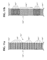
- a stent-graft 100" which is similar to the first stent-graft 100 described above.
- the stent-graft 100" has a flared proximal end 102", a flared distal end 104", and a midsection 106".
- the stent-graft 100" has a flexible reinforcement 105" attached to the midsection 106" and extending along substantially its entire length.
- the reinforcement is formed from a series of discrete members which are axially spaced apart from each other.
- This advantage can also be achieved with a reinforcement which is inlay knitted or woven into the graft component of the stent-graft, a reinforcement which is added to the outside of the stent-graft, or a reinforcement which is located between the stent and the graft.
- Figure 11b shows a stent-graft 100′′′ which is similar to the first stent-graft 100 described above.
- the stent-graft 100′′′ has a flared proximal end 102′′′, a flared distal end 104′′′, and a midsection 106′′′.
- the stent-graft 100"' has a first flexible reinforcement 105′′′ located between the proximal end 102′′′ and the midsection 106′′′ and a second flexible reinforcement 107′′′ located between the distal end 104′′′ and the midsection 106′′′.
- An advantage ofthis configuration is that it allows a small amount of additional axial compressibility which can be helpful during deployment.
- the stent is too long, it can be compressed axially to fit in the desired space.
- the pitch angle of the reinforcements 105′′′, 107′′′ can be made lower to add a small amount of longitudinal compressibility to the stent-graft while still maintaining a restriction on the radial expandability of the stent-graft.
- the reinforcement is flexible enough to allow the stent-graft to be pulled down to a small diameter for delivery to the deployment site, but be strong enough to limit the radial expansion of the stent-graft beyond a diameter which is substantially equal to the resting diameter of the stent-graft.
- the modular stent-graft system of the invention may include more than two stent-grafts.
- a modular system may include three stent-grafts 300, 400, 500 for bridging two aneurysms 604, 608 in a blood vessel 600 which exhibits three different diameters 602, 606, 610.
- the first stent-graft 300 has a flared proximal end 302, a non-flared distal end 304, and a midsection 306.
- the second stent-graft 400 has a non-flared proximal end 402, a non-flared distal end 404, and a midsection 406.
- the third stent-graft 500 has a flared proximal end 502, a non-flared distal end 504, and a midsection 506.
- the flared proximal end 302 ofthe first stent-graft 300 has an expanded diameter which fits securely in the large diameter portion 602 of the blood vessel 600 proximal of the first aneurysm 604.
- the second stent-graft 400 has a substantially constant expanded diameter which causes its proximal end 402 to fit securely in the midsection 306 ofthe first stent-graft 300 and its midsection 406 to fit securely in the smaller diameter section 606 ofthe blood vessel 600 between the first aneurysm 604 and the second aneurysm 608.
- the flared proximal end 502 of the third stent-graft 500 has an expanded diameter which fits securely in the midsection 406 of the second stent-graft 400; and the non-flared distal end 504 has an expanded diameter which fits securely in the smallest diameter portion 610 ofthe blood vessel 600 distal of the second aneurysm 608.
- the modular stent-grafts of Figure 12 are deployed in a manner similar to the stentgrafts shown in Figure 10, i.e. by deploying the proximal stent-graft first, and then following with distal stent-grafts. Although Figure 12 shows three stent-grafts with increasingly smaller diameters, the proximal to distal diameter change need not be from larger to smaller.
- the stent-grafts could be deployed in a different order or in the same order but with their proximal and distal ends reversed. That is, the stent-graft 400 could be deployed first and the stent-grafts 300 and 500 could be deployed inside the stent-graft 400. In this situation, it would be advantageous for the entire length of the stent-graft 400 to be reinforced. Alternatively, the stent-graft 300 could be deployed first with its end 302 being deployed distally, etc.
- the stent-graft system 700 has three stent-grafts 300', 400', and 500' which are similar to the stent-grafts 300, 400, and 500 described above.
- the primed reference numerals e.g. 302'
- the primed reference numerals refer to features of the stent-grafts 300', 400', and 500' which are similar to features of the stent-grafts 300, 400, and 500 described above.
- the proximal end 402' ofthe stent-graft 400' is pre-coupled to the midsection 306' of the stent-graft 300' and the proximal end 502' of the stent-graft 500' is pre-coupled to the midsection 406' of the stent-graft 400'.
- the pre-coupling may be effected at the time of manufacture, or by a practitioner prior to deployment of the modular stent-graft system. As shown in Figure 13, the pre-coupling is accomplished with sutures 401' and 501'.
- the stent-grafts may also be coupled to each other by wires, adhesives, welds, or by using any other suitable coupling method. After the stent-grafts 300', 400', and 500' are coupled to each other, they are "pulled down" as a single unit with the aid of an introducer to a compressed state as shown in Figure 14 for deployment.
- the modular stent-graft 100 described with reference to Figure 10 could be provided with a single flared end, the proximal end, rather than two flared ends, in order to fit in certain tortuous arteries.
- a bifurcated stent as shown in the parent application
- use an occluding device to block one of its legs.
Abstract
Description
Claims (19)
- A modular endoluminal stent-graft system for bridging a lesion in a blood vessel having a first large diameter on one side of the lesion and a second small diameter on the other side of the lesion, said system comprising:a) a first stent-graft having a first end, a second end, and a midsection, said first end of said first stent-graft having an expanded diameter equal to or slightly larger than the first large diameter ofthe blood vessel, said midsection of said first stent-graft having an expanded diameter which is smaller than said expanded diameter of said first end of said first stent-graft;b) a second stent-graft having a first end, a second end, and a midsection, said first end of said second stent-graft having an expanded diameter equal to or slightly larger than said expanded diameter of said midsection of said first stent-graft and said second end of said second stent-graft having an expanded diameter which is equal to or slightly larger than the second small diameter of the blood vessel, such that when said system is deployed, said first end of said first stent-graft engages the first large diameter ofthe blood vessel, said first end of said second stent-graft engages said midsection of said first stent-graft, and said second end of said second stent-graft engages the second small diameter ofthe blood vessel.
- A system according to claim 1, wherein said first end and/or said second end of said second stent-graft is flared.
- A modular stent-graft system, comprising:a) a first stent-graft having a first end, a second end, and a midsection, said first end of said first stent-graft having an expanded first diameter and said midsection of said first stent-graft having an expanded second diameter which is smaller than said expanded first diameter;b) a second stent-graft having a first end, a second end, and a midsection, said first end of said second stent-graft having an expanded third diameter equal to or slightly larger than said expanded second diameter of said midsection of said first stent-graft, such that when said system is deployed, said first end of said second stent-graft engages said midsection of said first stent-graft.
- A system according to claim 3, further comprising:
c) a third stent-graft having a first end, a second end, and a midsection, said first end of said third stent-graft having an expanded fourth diameter, wherein said midsection of said second stent-graft has an expanded fifth diameter equal to or slightly smaller than said expanded fourth diameter of said first end of said third stent-graft, such that when said system is deployed, said first end of said third stent-graft engages said midsection of said second stent-graft. - A system according to claim 4, wherein said first end of said third stent-graft is flared.
- A system according to any of claims 1 to 5, wherein said first end and/or said second end of said first stent-graft is flared.
- A system according to any of claims 1 to 6, wherein at least said midsection of said first stent-graft is reinforced with a flexible material.
- A system according to claim 7, wherein said flexible material comprises polyethylene terephthalate, nylon, polytetrafluoroethylene, polyolefin, polyamide, polycarbonate, polycarbonate urethane or metallic wire.
- A system according to claim 7, wherein said flexible material is selected from sutures, knits, weaves, braids, wires, and stents.
- A system according to any of claims 1 to 9, wherein said first end of said second stent-graft is coupled to said first stent-graft by one of sutures, wires, adhesive and welds.
- A modular stent-graft system, comprising:a) a first stent-graft having a first end, a second end, and a midsection defining a first lumen therethrough, said midsection of said first stent-graft having an expanded first diameter;b) a second stent-graft having a first end, a second end, and a midsection defining a second lumen therethrough, said midsection of said second stent-graft having an expanded second diameter smaller than said expanded first diameter, said first end of said second stent-graft being coupled to said first stent-graft such that said first lumen is substantially contiguous with said second lumen.
- A system according to claim 11, wherein said first end of said second stent-graft is coupled to said midsection of said first stent-graft.
- A self-expanding endoluminal stent-graft, comprising:a) a self-expanding stent having a geometry such that when ends of said stent are pulled apart, the diameter of said stent decreases to between approximately one halfto approximately one tenth of a resting diameter of said stent; andb) a flexible reinforcement coupled to at least one portion of said stent and substantially limiting radial expansion of said portion of said stent beyond said resting diameter.
- A stent-graft according to claim 13, wherein said at least one portion includes a central portion of said stent
- A stent-graft according to claim 13, wherein said at least one portion includes two end portions of said stent.
- A stent-graft according to any of claims 13 to 15, wherein said reinforcement includes a continuous member which extends over a length of said stent.
- A stent-graft according to claim 13 to 15, wherein said reinforcement includes a plurality of discrete members which are spaced apart from each other axially.
- A method of bridging a lesion in a blood vessel having a first large diameter on one side of the lesion and a second small diameter on the other side of the lesion, said method comprising:a) obtaining a first stent-graft having a first end, a second end, and a midsection, said first end of said first stent-graft having an expanded diameter equal to or slightly larger than the first large diameter of the blood vessel, said midsection of said first stent-graft having an expanded diameter which is smaller than said expanded diameter of said first end of said first stent-graft;b) obtaining a second stent-graft having a first end, a second end, and a midsection, said first end of said second stent-graft having an expanded diameter equal to or slightly larger than said expanded diameter of said midsection of said first stent-graft and said second end of said second stent-graft having an expanded diameter which is equal to or slightly larger than the second small diameter of the blood vessel;c) deploying said first stent-graft by expanding said first stent-graft such that said first end of said first stent-graft engages the first large diameter of the blood vessel; andd) deploying said second stent-graft by expanding said second stent-graft such that said first end of said second stent-graft engages said midsection of said first stent-graft and said second end of said second stent-graft engages the second small diameter of the blood vessel.
- A method according to claim 18, further comprising:e) obtaining a third stent-graft having a first end, a second end, and a midsection; andf) deploying said third stent-graft by expanding said third stent-graft such that said first end of said third stent-graft engages said midsection of said second stent-graft.
Applications Claiming Priority (2)
| Application Number | Priority Date | Filing Date | Title |
|---|---|---|---|
| US80673997A | 1997-02-27 | 1997-02-27 | |
| US806739 | 1997-02-27 |
Publications (3)
| Publication Number | Publication Date |
|---|---|
| EP0861638A2 true EP0861638A2 (en) | 1998-09-02 |
| EP0861638A3 EP0861638A3 (en) | 1998-11-11 |
| EP0861638B1 EP0861638B1 (en) | 2005-09-14 |
Family
ID=25194743
Family Applications (1)
| Application Number | Title | Priority Date | Filing Date |
|---|---|---|---|
| EP19980301345 Expired - Lifetime EP0861638B1 (en) | 1997-02-27 | 1998-02-24 | Modular endoluminal stent-grafts |
Country Status (5)
| Country | Link |
|---|---|
| EP (1) | EP0861638B1 (en) |
| JP (1) | JP3051104B2 (en) |
| AU (1) | AU726881B2 (en) |
| CA (1) | CA2229685C (en) |
| DE (1) | DE69831521T2 (en) |
Cited By (11)
| Publication number | Priority date | Publication date | Assignee | Title |
|---|---|---|---|---|
| WO2003063734A1 (en) * | 2002-01-29 | 2003-08-07 | Medtronic Ave, Inc. | Flared stent and method of use |
| EP1367963A2 (en) * | 2001-03-13 | 2003-12-10 | Yoram Richter | Method and apparatus for stenting |
| US7396363B2 (en) * | 2002-06-18 | 2008-07-08 | F.R.I.D. R&D Benelux | Hemodynamic luminal endoprosthesis |
| WO2009077805A1 (en) * | 2007-12-19 | 2009-06-25 | Invatec Technology Center Gmbh | Modular stent assembly |
| US20090171436A1 (en) * | 2005-11-09 | 2009-07-02 | Casanova R Michael | Grafts and stent grafts having a radiopaque beading |
| US7862609B2 (en) | 2000-11-16 | 2011-01-04 | Cordis Corporation | Stent graft having a pleated graft member |
| WO2015038875A1 (en) * | 2013-09-13 | 2015-03-19 | Abbott Cardiovascular Systems Inc. | Braided scaffolds |
| WO2015120120A1 (en) * | 2014-02-07 | 2015-08-13 | Cook Medical Technologies Llc | Telescoping stent |
| US9155491B2 (en) | 2005-11-09 | 2015-10-13 | C.R. Bard, Inc. | Grafts and stent grafts having a radiopaque marker |
| EP1029518B2 (en) † | 1999-02-16 | 2015-11-25 | Lavant International S.A. | Aortic graft for treating abdominal aortic aneurysms and use of the graft |
| US10582997B2 (en) | 2004-08-31 | 2020-03-10 | C. R. Bard, Inc. | Self-sealing PTFE graft with kink resistance |
Families Citing this family (7)
| Publication number | Priority date | Publication date | Assignee | Title |
|---|---|---|---|---|
| US6315708B1 (en) * | 2000-03-31 | 2001-11-13 | Cordis Corporation | Stent with self-expanding end sections |
| JP4707227B2 (en) * | 2000-12-27 | 2011-06-22 | グンゼ株式会社 | Biological duct stent |
| JP2002233580A (en) * | 2001-02-09 | 2002-08-20 | Ichiro Hino | Stent graft |
| IL158960A0 (en) * | 2003-11-19 | 2004-05-12 | Neovasc Medical Ltd | Vascular implant |
| AU2005282782B2 (en) * | 2004-09-02 | 2010-07-29 | Cook Medical Technologies Llc | Modular prosthesis and method for branch vessels |
| JP2011224123A (en) * | 2010-04-19 | 2011-11-10 | Kanji Inoue | Stent |
| CA3133857A1 (en) | 2019-03-20 | 2020-09-24 | inQB8 Medical Technologies, LLC | Aortic dissection implant |
Citations (2)
| Publication number | Priority date | Publication date | Assignee | Title |
|---|---|---|---|---|
| GB1205743A (en) | 1966-07-15 | 1970-09-16 | Nat Res Dev | Surgical dilator |
| US4655771A (en) | 1982-04-30 | 1987-04-07 | Shepherd Patents S.A. | Prosthesis comprising an expansible or contractile tubular body |
Family Cites Families (5)
| Publication number | Priority date | Publication date | Assignee | Title |
|---|---|---|---|---|
| US5064435A (en) * | 1990-06-28 | 1991-11-12 | Schneider (Usa) Inc. | Self-expanding prosthesis having stable axial length |
| AU8012394A (en) * | 1993-10-01 | 1995-05-01 | Emory University | Self-expanding intraluminal composite prosthesis |
| DE4418336A1 (en) * | 1994-05-26 | 1995-11-30 | Angiomed Ag | Stent for widening and holding open receptacles |
| US5683449A (en) * | 1995-02-24 | 1997-11-04 | Marcade; Jean Paul | Modular bifurcated intraluminal grafts and methods for delivering and assembling same |
| ATE270528T1 (en) * | 1995-04-12 | 2004-07-15 | Corvita Europ | SELF-EXPANDING STENT FOR INTRODUCING A MEDICAL DEVICE INTO A BODY CAVITY AND METHOD OF MANUFACTURING |
-
1998
- 1998-02-16 CA CA 2229685 patent/CA2229685C/en not_active Expired - Fee Related
- 1998-02-24 DE DE1998631521 patent/DE69831521T2/en not_active Expired - Lifetime
- 1998-02-24 EP EP19980301345 patent/EP0861638B1/en not_active Expired - Lifetime
- 1998-02-25 JP JP4362498A patent/JP3051104B2/en not_active Expired - Fee Related
- 1998-02-26 AU AU56337/98A patent/AU726881B2/en not_active Ceased
Patent Citations (5)
| Publication number | Priority date | Publication date | Assignee | Title |
|---|---|---|---|---|
| GB1205743A (en) | 1966-07-15 | 1970-09-16 | Nat Res Dev | Surgical dilator |
| US4655771A (en) | 1982-04-30 | 1987-04-07 | Shepherd Patents S.A. | Prosthesis comprising an expansible or contractile tubular body |
| US4954126A (en) | 1982-04-30 | 1990-09-04 | Shepherd Patents S.A. | Prosthesis comprising an expansible or contractile tubular body |
| US4954126B1 (en) | 1982-04-30 | 1996-05-28 | Ams Med Invent S A | Prosthesis comprising an expansible or contractile tubular body |
| US4655771B1 (en) | 1982-04-30 | 1996-09-10 | Medinvent Ams Sa | Prosthesis comprising an expansible or contractile tubular body |
Cited By (20)
| Publication number | Priority date | Publication date | Assignee | Title |
|---|---|---|---|---|
| EP1029518B2 (en) † | 1999-02-16 | 2015-11-25 | Lavant International S.A. | Aortic graft for treating abdominal aortic aneurysms and use of the graft |
| US7862609B2 (en) | 2000-11-16 | 2011-01-04 | Cordis Corporation | Stent graft having a pleated graft member |
| EP2145608A1 (en) * | 2001-03-13 | 2010-01-20 | Yoram Richter | Stent for improved blood flow |
| EP1367963A2 (en) * | 2001-03-13 | 2003-12-10 | Yoram Richter | Method and apparatus for stenting |
| US9492293B2 (en) | 2001-03-13 | 2016-11-15 | Medinol Ltd. | Method and apparatus for stenting |
| EP1367963A4 (en) * | 2001-03-13 | 2007-06-20 | Yoram Richter | Method and apparatus for stenting |
| EP2158875A1 (en) * | 2001-03-13 | 2010-03-03 | Yoram Richter | Stent and kit comprising a stent and a balloon for improving blood flow |
| US7867269B2 (en) | 2002-01-29 | 2011-01-11 | Medtronic Vascular, Inc. | Flared stent and method for use |
| WO2003063734A1 (en) * | 2002-01-29 | 2003-08-07 | Medtronic Ave, Inc. | Flared stent and method of use |
| US6964681B2 (en) | 2002-01-29 | 2005-11-15 | Medtronic Vascular, Inc. | Flared stent and method of use |
| US7396363B2 (en) * | 2002-06-18 | 2008-07-08 | F.R.I.D. R&D Benelux | Hemodynamic luminal endoprosthesis |
| US10582997B2 (en) | 2004-08-31 | 2020-03-10 | C. R. Bard, Inc. | Self-sealing PTFE graft with kink resistance |
| US20090171436A1 (en) * | 2005-11-09 | 2009-07-02 | Casanova R Michael | Grafts and stent grafts having a radiopaque beading |
| US9155491B2 (en) | 2005-11-09 | 2015-10-13 | C.R. Bard, Inc. | Grafts and stent grafts having a radiopaque marker |
| WO2009077805A1 (en) * | 2007-12-19 | 2009-06-25 | Invatec Technology Center Gmbh | Modular stent assembly |
| CN101902992B (en) * | 2007-12-19 | 2012-11-28 | 因瓦泰克技术中心有限公司 | Modular stent assembly |
| WO2015038875A1 (en) * | 2013-09-13 | 2015-03-19 | Abbott Cardiovascular Systems Inc. | Braided scaffolds |
| US10004834B2 (en) | 2013-09-13 | 2018-06-26 | Abbott Cardiovascular Systems Inc. | Braided scaffolds |
| WO2015120120A1 (en) * | 2014-02-07 | 2015-08-13 | Cook Medical Technologies Llc | Telescoping stent |
| US9937067B2 (en) | 2014-02-07 | 2018-04-10 | Cook Medical Technologies Llc | Telescoping ureteral stent |
Also Published As
| Publication number | Publication date |
|---|---|
| JP3051104B2 (en) | 2000-06-12 |
| AU5633798A (en) | 1998-09-03 |
| EP0861638A3 (en) | 1998-11-11 |
| EP0861638B1 (en) | 2005-09-14 |
| AU726881B2 (en) | 2000-11-23 |
| DE69831521T2 (en) | 2006-06-14 |
| CA2229685C (en) | 2003-09-02 |
| JPH10234861A (en) | 1998-09-08 |
| DE69831521D1 (en) | 2005-10-20 |
| CA2229685A1 (en) | 1998-08-27 |
Similar Documents
| Publication | Publication Date | Title |
|---|---|---|
| US6348066B1 (en) | Modular endoluminal stent-grafts and methods for their use | |
| EP0861638B1 (en) | Modular endoluminal stent-grafts | |
| AU2003200089B2 (en) | Covered segmented stent | |
| AU2007221953B2 (en) | Intravascular deliverable stent for reinforcement of vascular abnormalities | |
| US7833259B2 (en) | Fenestrated endoluminal stent system | |
| US7794487B2 (en) | Reduced deployment force delivery device | |
| EP1513471B1 (en) | Endoluminal device having barb assembly | |
| EP1061985B1 (en) | Delivery system for deployment and endovascular assembly of multi-stage stent graft | |
| US8518096B2 (en) | Elephant trunk thoracic endograft and delivery system | |
| US6344054B1 (en) | Endoluminal prosthesis comprising stent and overlying graft cover, and system and method for deployment thereof | |
| US7674284B2 (en) | Endoluminal graft | |
| US9848869B2 (en) | Prosthesis systems and methods | |
| EP1763327B1 (en) | Balloon / self-expanding stent graft | |
| EP1795152B1 (en) | Systems and methods for securing graft material to intraluminal devices | |
| EP1356785B1 (en) | Bifurcated endoluminal prosthetic assembly | |
| EP1599152A1 (en) | Endoluminal device having enhanced affixation characteristics | |
| AU754236B2 (en) | Self-expanding endoluminal stent-grafts and methods for their use |
Legal Events
| Date | Code | Title | Description |
|---|---|---|---|
| PUAI | Public reference made under article 153(3) epc to a published international application that has entered the european phase |
Free format text: ORIGINAL CODE: 0009012 |
|
| AK | Designated contracting states |
Kind code of ref document: A2 Designated state(s): DE FR GB IE NL |
|
| AX | Request for extension of the european patent |
Free format text: AL;LT;LV;MK;RO;SI |
|
| PUAL | Search report despatched |
Free format text: ORIGINAL CODE: 0009013 |
|
| AK | Designated contracting states |
Kind code of ref document: A3 Designated state(s): AT BE CH DE DK ES FI FR GB GR IE IT LI LU MC NL PT SE |
|
| AX | Request for extension of the european patent |
Free format text: AL;LT;LV;MK;RO;SI |
|
| RTI1 | Title (correction) | ||
| 17P | Request for examination filed |
Effective date: 19990426 |
|
| AKX | Designation fees paid |
Free format text: AT BE CH DE DK LI |
|
| RBV | Designated contracting states (corrected) |
Designated state(s): DE FR GB IE NL |
|
| 17Q | First examination report despatched |
Effective date: 20021218 |
|
| GRAP | Despatch of communication of intention to grant a patent |
Free format text: ORIGINAL CODE: EPIDOSNIGR1 |
|
| GRAS | Grant fee paid |
Free format text: ORIGINAL CODE: EPIDOSNIGR3 |
|
| GRAA | (expected) grant |
Free format text: ORIGINAL CODE: 0009210 |
|
| AK | Designated contracting states |
Kind code of ref document: B1 Designated state(s): DE FR GB IE NL |
|
| REG | Reference to a national code |
Ref country code: GB Ref legal event code: FG4D |
|
| REG | Reference to a national code |
Ref country code: IE Ref legal event code: FG4D |
|
| REF | Corresponds to: |
Ref document number: 69831521 Country of ref document: DE Date of ref document: 20051020 Kind code of ref document: P |
|
| PGFP | Annual fee paid to national office [announced via postgrant information from national office to epo] |
Ref country code: FR Payment date: 20060403 Year of fee payment: 9 |
|
| PLBE | No opposition filed within time limit |
Free format text: ORIGINAL CODE: 0009261 |
|
| STAA | Information on the status of an ep patent application or granted ep patent |
Free format text: STATUS: NO OPPOSITION FILED WITHIN TIME LIMIT |
|
| 26N | No opposition filed |
Effective date: 20060615 |
|
| PG25 | Lapsed in a contracting state [announced via postgrant information from national office to epo] |
Ref country code: FR Free format text: LAPSE BECAUSE OF FAILURE TO SUBMIT A TRANSLATION OF THE DESCRIPTION OR TO PAY THE FEE WITHIN THE PRESCRIBED TIME-LIMIT Effective date: 20061020 |
|
| EN | Fr: translation not filed | ||
| EN | Fr: translation not filed | ||
| PGFP | Annual fee paid to national office [announced via postgrant information from national office to epo] |
Ref country code: NL Payment date: 20090210 Year of fee payment: 12 |
|
| PGFP | Annual fee paid to national office [announced via postgrant information from national office to epo] |
Ref country code: GB Payment date: 20090106 Year of fee payment: 12 |
|
| REG | Reference to a national code |
Ref country code: NL Ref legal event code: V1 Effective date: 20100901 |
|
| GBPC | Gb: european patent ceased through non-payment of renewal fee |
Effective date: 20100224 |
|
| PG25 | Lapsed in a contracting state [announced via postgrant information from national office to epo] |
Ref country code: NL Free format text: LAPSE BECAUSE OF NON-PAYMENT OF DUE FEES Effective date: 20100901 |
|
| PG25 | Lapsed in a contracting state [announced via postgrant information from national office to epo] |
Ref country code: GB Free format text: LAPSE BECAUSE OF NON-PAYMENT OF DUE FEES Effective date: 20100224 |
|
| PGFP | Annual fee paid to national office [announced via postgrant information from national office to epo] |
Ref country code: IE Payment date: 20150210 Year of fee payment: 18 Ref country code: DE Payment date: 20150218 Year of fee payment: 18 |
|
| REG | Reference to a national code |
Ref country code: DE Ref legal event code: R119 Ref document number: 69831521 Country of ref document: DE |
|
| REG | Reference to a national code |
Ref country code: IE Ref legal event code: MM4A |
|
| PG25 | Lapsed in a contracting state [announced via postgrant information from national office to epo] |
Ref country code: DE Free format text: LAPSE BECAUSE OF NON-PAYMENT OF DUE FEES Effective date: 20160901 Ref country code: IE Free format text: LAPSE BECAUSE OF NON-PAYMENT OF DUE FEES Effective date: 20160224 |