EP0862395B1 - Low-wear ball and cup joint prosthesis - Google Patents
Low-wear ball and cup joint prosthesis Download PDFInfo
- Publication number
- EP0862395B1 EP0862395B1 EP96938674A EP96938674A EP0862395B1 EP 0862395 B1 EP0862395 B1 EP 0862395B1 EP 96938674 A EP96938674 A EP 96938674A EP 96938674 A EP96938674 A EP 96938674A EP 0862395 B1 EP0862395 B1 EP 0862395B1
- Authority
- EP
- European Patent Office
- Prior art keywords
- area
- intimate contact
- articulating
- cup
- ball
- Prior art date
- Legal status (The legal status is an assumption and is not a legal conclusion. Google has not performed a legal analysis and makes no representation as to the accuracy of the status listed.)
- Expired - Lifetime
Links
Images

Classifications
-
- A—HUMAN NECESSITIES
- A61—MEDICAL OR VETERINARY SCIENCE; HYGIENE
- A61F—FILTERS IMPLANTABLE INTO BLOOD VESSELS; PROSTHESES; DEVICES PROVIDING PATENCY TO, OR PREVENTING COLLAPSING OF, TUBULAR STRUCTURES OF THE BODY, e.g. STENTS; ORTHOPAEDIC, NURSING OR CONTRACEPTIVE DEVICES; FOMENTATION; TREATMENT OR PROTECTION OF EYES OR EARS; BANDAGES, DRESSINGS OR ABSORBENT PADS; FIRST-AID KITS
- A61F2/00—Filters implantable into blood vessels; Prostheses, i.e. artificial substitutes or replacements for parts of the body; Appliances for connecting them with the body; Devices providing patency to, or preventing collapsing of, tubular structures of the body, e.g. stents
- A61F2/02—Prostheses implantable into the body
- A61F2/30—Joints
- A61F2/32—Joints for the hip
-
- A—HUMAN NECESSITIES
- A61—MEDICAL OR VETERINARY SCIENCE; HYGIENE
- A61F—FILTERS IMPLANTABLE INTO BLOOD VESSELS; PROSTHESES; DEVICES PROVIDING PATENCY TO, OR PREVENTING COLLAPSING OF, TUBULAR STRUCTURES OF THE BODY, e.g. STENTS; ORTHOPAEDIC, NURSING OR CONTRACEPTIVE DEVICES; FOMENTATION; TREATMENT OR PROTECTION OF EYES OR EARS; BANDAGES, DRESSINGS OR ABSORBENT PADS; FIRST-AID KITS
- A61F2/00—Filters implantable into blood vessels; Prostheses, i.e. artificial substitutes or replacements for parts of the body; Appliances for connecting them with the body; Devices providing patency to, or preventing collapsing of, tubular structures of the body, e.g. stents
- A61F2/02—Prostheses implantable into the body
- A61F2/30—Joints
- A61F2/30767—Special external or bone-contacting surface, e.g. coating for improving bone ingrowth
-
- A—HUMAN NECESSITIES
- A61—MEDICAL OR VETERINARY SCIENCE; HYGIENE
- A61F—FILTERS IMPLANTABLE INTO BLOOD VESSELS; PROSTHESES; DEVICES PROVIDING PATENCY TO, OR PREVENTING COLLAPSING OF, TUBULAR STRUCTURES OF THE BODY, e.g. STENTS; ORTHOPAEDIC, NURSING OR CONTRACEPTIVE DEVICES; FOMENTATION; TREATMENT OR PROTECTION OF EYES OR EARS; BANDAGES, DRESSINGS OR ABSORBENT PADS; FIRST-AID KITS
- A61F2/00—Filters implantable into blood vessels; Prostheses, i.e. artificial substitutes or replacements for parts of the body; Appliances for connecting them with the body; Devices providing patency to, or preventing collapsing of, tubular structures of the body, e.g. stents
- A61F2/02—Prostheses implantable into the body
- A61F2/30—Joints
- A61F2002/30001—Additional features of subject-matter classified in A61F2/28, A61F2/30 and subgroups thereof
- A61F2002/30003—Material related properties of the prosthesis or of a coating on the prosthesis
- A61F2002/30004—Material related properties of the prosthesis or of a coating on the prosthesis the prosthesis being made from materials having different values of a given property at different locations within the same prosthesis
- A61F2002/30037—Material related properties of the prosthesis or of a coating on the prosthesis the prosthesis being made from materials having different values of a given property at different locations within the same prosthesis differing in coefficient of thermal expansion or dila(ta)tion
-
- A—HUMAN NECESSITIES
- A61—MEDICAL OR VETERINARY SCIENCE; HYGIENE
- A61F—FILTERS IMPLANTABLE INTO BLOOD VESSELS; PROSTHESES; DEVICES PROVIDING PATENCY TO, OR PREVENTING COLLAPSING OF, TUBULAR STRUCTURES OF THE BODY, e.g. STENTS; ORTHOPAEDIC, NURSING OR CONTRACEPTIVE DEVICES; FOMENTATION; TREATMENT OR PROTECTION OF EYES OR EARS; BANDAGES, DRESSINGS OR ABSORBENT PADS; FIRST-AID KITS
- A61F2/00—Filters implantable into blood vessels; Prostheses, i.e. artificial substitutes or replacements for parts of the body; Appliances for connecting them with the body; Devices providing patency to, or preventing collapsing of, tubular structures of the body, e.g. stents
- A61F2/02—Prostheses implantable into the body
- A61F2/30—Joints
- A61F2002/30001—Additional features of subject-matter classified in A61F2/28, A61F2/30 and subgroups thereof
- A61F2002/30621—Features concerning the anatomical functioning or articulation of the prosthetic joint
- A61F2002/30649—Ball-and-socket joints
- A61F2002/30654—Details of the concave socket
- A61F2002/30655—Non-spherical concave inner surface
- A61F2002/30657—Non-spherical concave inner surface made of different partially-spherical concave portions
- A61F2002/30658—Non-spherical concave inner surface made of different partially-spherical concave portions having a central conforming area surrounded by a peripheral annular non-conforming area
-
- A—HUMAN NECESSITIES
- A61—MEDICAL OR VETERINARY SCIENCE; HYGIENE
- A61F—FILTERS IMPLANTABLE INTO BLOOD VESSELS; PROSTHESES; DEVICES PROVIDING PATENCY TO, OR PREVENTING COLLAPSING OF, TUBULAR STRUCTURES OF THE BODY, e.g. STENTS; ORTHOPAEDIC, NURSING OR CONTRACEPTIVE DEVICES; FOMENTATION; TREATMENT OR PROTECTION OF EYES OR EARS; BANDAGES, DRESSINGS OR ABSORBENT PADS; FIRST-AID KITS
- A61F2/00—Filters implantable into blood vessels; Prostheses, i.e. artificial substitutes or replacements for parts of the body; Appliances for connecting them with the body; Devices providing patency to, or preventing collapsing of, tubular structures of the body, e.g. stents
- A61F2/02—Prostheses implantable into the body
- A61F2/30—Joints
- A61F2002/30001—Additional features of subject-matter classified in A61F2/28, A61F2/30 and subgroups thereof
- A61F2002/30667—Features concerning an interaction with the environment or a particular use of the prosthesis
- A61F2002/30673—Lubricating means, e.g. synovial pocket
-
- A—HUMAN NECESSITIES
- A61—MEDICAL OR VETERINARY SCIENCE; HYGIENE
- A61F—FILTERS IMPLANTABLE INTO BLOOD VESSELS; PROSTHESES; DEVICES PROVIDING PATENCY TO, OR PREVENTING COLLAPSING OF, TUBULAR STRUCTURES OF THE BODY, e.g. STENTS; ORTHOPAEDIC, NURSING OR CONTRACEPTIVE DEVICES; FOMENTATION; TREATMENT OR PROTECTION OF EYES OR EARS; BANDAGES, DRESSINGS OR ABSORBENT PADS; FIRST-AID KITS
- A61F2/00—Filters implantable into blood vessels; Prostheses, i.e. artificial substitutes or replacements for parts of the body; Appliances for connecting them with the body; Devices providing patency to, or preventing collapsing of, tubular structures of the body, e.g. stents
- A61F2/02—Prostheses implantable into the body
- A61F2/30—Joints
- A61F2002/30001—Additional features of subject-matter classified in A61F2/28, A61F2/30 and subgroups thereof
- A61F2002/30667—Features concerning an interaction with the environment or a particular use of the prosthesis
- A61F2002/30682—Means for preventing migration of particles released by the joint, e.g. wear debris or cement particles
- A61F2002/30685—Means for reducing or preventing the generation of wear particulates
-
- A—HUMAN NECESSITIES
- A61—MEDICAL OR VETERINARY SCIENCE; HYGIENE
- A61F—FILTERS IMPLANTABLE INTO BLOOD VESSELS; PROSTHESES; DEVICES PROVIDING PATENCY TO, OR PREVENTING COLLAPSING OF, TUBULAR STRUCTURES OF THE BODY, e.g. STENTS; ORTHOPAEDIC, NURSING OR CONTRACEPTIVE DEVICES; FOMENTATION; TREATMENT OR PROTECTION OF EYES OR EARS; BANDAGES, DRESSINGS OR ABSORBENT PADS; FIRST-AID KITS
- A61F2/00—Filters implantable into blood vessels; Prostheses, i.e. artificial substitutes or replacements for parts of the body; Appliances for connecting them with the body; Devices providing patency to, or preventing collapsing of, tubular structures of the body, e.g. stents
- A61F2/02—Prostheses implantable into the body
- A61F2/30—Joints
- A61F2/30767—Special external or bone-contacting surface, e.g. coating for improving bone ingrowth
- A61F2002/30922—Hardened surfaces
-
- A—HUMAN NECESSITIES
- A61—MEDICAL OR VETERINARY SCIENCE; HYGIENE
- A61F—FILTERS IMPLANTABLE INTO BLOOD VESSELS; PROSTHESES; DEVICES PROVIDING PATENCY TO, OR PREVENTING COLLAPSING OF, TUBULAR STRUCTURES OF THE BODY, e.g. STENTS; ORTHOPAEDIC, NURSING OR CONTRACEPTIVE DEVICES; FOMENTATION; TREATMENT OR PROTECTION OF EYES OR EARS; BANDAGES, DRESSINGS OR ABSORBENT PADS; FIRST-AID KITS
- A61F2/00—Filters implantable into blood vessels; Prostheses, i.e. artificial substitutes or replacements for parts of the body; Appliances for connecting them with the body; Devices providing patency to, or preventing collapsing of, tubular structures of the body, e.g. stents
- A61F2/02—Prostheses implantable into the body
- A61F2/30—Joints
- A61F2/30767—Special external or bone-contacting surface, e.g. coating for improving bone ingrowth
- A61F2002/30934—Special articulating surfaces
- A61F2002/30935—Concave articulating surface composed of a central conforming area surrounded by a peripheral annular non-conforming area
-
- A—HUMAN NECESSITIES
- A61—MEDICAL OR VETERINARY SCIENCE; HYGIENE
- A61F—FILTERS IMPLANTABLE INTO BLOOD VESSELS; PROSTHESES; DEVICES PROVIDING PATENCY TO, OR PREVENTING COLLAPSING OF, TUBULAR STRUCTURES OF THE BODY, e.g. STENTS; ORTHOPAEDIC, NURSING OR CONTRACEPTIVE DEVICES; FOMENTATION; TREATMENT OR PROTECTION OF EYES OR EARS; BANDAGES, DRESSINGS OR ABSORBENT PADS; FIRST-AID KITS
- A61F2/00—Filters implantable into blood vessels; Prostheses, i.e. artificial substitutes or replacements for parts of the body; Appliances for connecting them with the body; Devices providing patency to, or preventing collapsing of, tubular structures of the body, e.g. stents
- A61F2/02—Prostheses implantable into the body
- A61F2/30—Joints
- A61F2/3094—Designing or manufacturing processes
- A61F2/30942—Designing or manufacturing processes for designing or making customized prostheses, e.g. using templates, CT or NMR scans, finite-element analysis or CAD-CAM techniques
- A61F2002/30943—Designing or manufacturing processes for designing or making customized prostheses, e.g. using templates, CT or NMR scans, finite-element analysis or CAD-CAM techniques using mathematical models
-
- A—HUMAN NECESSITIES
- A61—MEDICAL OR VETERINARY SCIENCE; HYGIENE
- A61F—FILTERS IMPLANTABLE INTO BLOOD VESSELS; PROSTHESES; DEVICES PROVIDING PATENCY TO, OR PREVENTING COLLAPSING OF, TUBULAR STRUCTURES OF THE BODY, e.g. STENTS; ORTHOPAEDIC, NURSING OR CONTRACEPTIVE DEVICES; FOMENTATION; TREATMENT OR PROTECTION OF EYES OR EARS; BANDAGES, DRESSINGS OR ABSORBENT PADS; FIRST-AID KITS
- A61F2/00—Filters implantable into blood vessels; Prostheses, i.e. artificial substitutes or replacements for parts of the body; Appliances for connecting them with the body; Devices providing patency to, or preventing collapsing of, tubular structures of the body, e.g. stents
- A61F2/02—Prostheses implantable into the body
- A61F2/30—Joints
- A61F2/32—Joints for the hip
- A61F2002/3225—Joints for the hip the diameter of the inner concave femoral head-receiving cavity of the inner acetabular shell being essentially greater than the diameter of the convex femoral head
-
- A—HUMAN NECESSITIES
- A61—MEDICAL OR VETERINARY SCIENCE; HYGIENE
- A61F—FILTERS IMPLANTABLE INTO BLOOD VESSELS; PROSTHESES; DEVICES PROVIDING PATENCY TO, OR PREVENTING COLLAPSING OF, TUBULAR STRUCTURES OF THE BODY, e.g. STENTS; ORTHOPAEDIC, NURSING OR CONTRACEPTIVE DEVICES; FOMENTATION; TREATMENT OR PROTECTION OF EYES OR EARS; BANDAGES, DRESSINGS OR ABSORBENT PADS; FIRST-AID KITS
- A61F2/00—Filters implantable into blood vessels; Prostheses, i.e. artificial substitutes or replacements for parts of the body; Appliances for connecting them with the body; Devices providing patency to, or preventing collapsing of, tubular structures of the body, e.g. stents
- A61F2/02—Prostheses implantable into the body
- A61F2/30—Joints
- A61F2/32—Joints for the hip
- A61F2/34—Acetabular cups
- A61F2002/3412—Acetabular cups with pins or protrusions, e.g. non-sharp pins or protrusions projecting from a shell surface
- A61F2002/3417—Acetabular cups with pins or protrusions, e.g. non-sharp pins or protrusions projecting from a shell surface the outer shell having protrusions on meridian lines, e.g. equidistant fins or wings around the equatorial zone
-
- A—HUMAN NECESSITIES
- A61—MEDICAL OR VETERINARY SCIENCE; HYGIENE
- A61F—FILTERS IMPLANTABLE INTO BLOOD VESSELS; PROSTHESES; DEVICES PROVIDING PATENCY TO, OR PREVENTING COLLAPSING OF, TUBULAR STRUCTURES OF THE BODY, e.g. STENTS; ORTHOPAEDIC, NURSING OR CONTRACEPTIVE DEVICES; FOMENTATION; TREATMENT OR PROTECTION OF EYES OR EARS; BANDAGES, DRESSINGS OR ABSORBENT PADS; FIRST-AID KITS
- A61F2/00—Filters implantable into blood vessels; Prostheses, i.e. artificial substitutes or replacements for parts of the body; Appliances for connecting them with the body; Devices providing patency to, or preventing collapsing of, tubular structures of the body, e.g. stents
- A61F2/02—Prostheses implantable into the body
- A61F2/30—Joints
- A61F2/32—Joints for the hip
- A61F2/34—Acetabular cups
- A61F2002/3453—Acetabular cups having a non-hemispherical convex outer surface, e.g. quadric-shaped
- A61F2002/3459—Acetabular cups having a non-hemispherical convex outer surface, e.g. quadric-shaped made of different partially-spherical portions
-
- A—HUMAN NECESSITIES
- A61—MEDICAL OR VETERINARY SCIENCE; HYGIENE
- A61F—FILTERS IMPLANTABLE INTO BLOOD VESSELS; PROSTHESES; DEVICES PROVIDING PATENCY TO, OR PREVENTING COLLAPSING OF, TUBULAR STRUCTURES OF THE BODY, e.g. STENTS; ORTHOPAEDIC, NURSING OR CONTRACEPTIVE DEVICES; FOMENTATION; TREATMENT OR PROTECTION OF EYES OR EARS; BANDAGES, DRESSINGS OR ABSORBENT PADS; FIRST-AID KITS
- A61F2/00—Filters implantable into blood vessels; Prostheses, i.e. artificial substitutes or replacements for parts of the body; Appliances for connecting them with the body; Devices providing patency to, or preventing collapsing of, tubular structures of the body, e.g. stents
- A61F2/02—Prostheses implantable into the body
- A61F2/30—Joints
- A61F2/32—Joints for the hip
- A61F2/36—Femoral heads ; Femoral endoprostheses
- A61F2/3609—Femoral heads or necks; Connections of endoprosthetic heads or necks to endoprosthetic femoral shafts
- A61F2002/3611—Heads or epiphyseal parts of femur
- A61F2002/3623—Non-spherical heads
-
- A—HUMAN NECESSITIES
- A61—MEDICAL OR VETERINARY SCIENCE; HYGIENE
- A61F—FILTERS IMPLANTABLE INTO BLOOD VESSELS; PROSTHESES; DEVICES PROVIDING PATENCY TO, OR PREVENTING COLLAPSING OF, TUBULAR STRUCTURES OF THE BODY, e.g. STENTS; ORTHOPAEDIC, NURSING OR CONTRACEPTIVE DEVICES; FOMENTATION; TREATMENT OR PROTECTION OF EYES OR EARS; BANDAGES, DRESSINGS OR ABSORBENT PADS; FIRST-AID KITS
- A61F2/00—Filters implantable into blood vessels; Prostheses, i.e. artificial substitutes or replacements for parts of the body; Appliances for connecting them with the body; Devices providing patency to, or preventing collapsing of, tubular structures of the body, e.g. stents
- A61F2/02—Prostheses implantable into the body
- A61F2/30—Joints
- A61F2/46—Special tools or methods for implanting or extracting artificial joints, accessories, bone grafts or substitutes, or particular adaptations therefor
- A61F2002/4631—Special tools or methods for implanting or extracting artificial joints, accessories, bone grafts or substitutes, or particular adaptations therefor the prosthesis being specially adapted for being cemented
-
- A—HUMAN NECESSITIES
- A61—MEDICAL OR VETERINARY SCIENCE; HYGIENE
- A61F—FILTERS IMPLANTABLE INTO BLOOD VESSELS; PROSTHESES; DEVICES PROVIDING PATENCY TO, OR PREVENTING COLLAPSING OF, TUBULAR STRUCTURES OF THE BODY, e.g. STENTS; ORTHOPAEDIC, NURSING OR CONTRACEPTIVE DEVICES; FOMENTATION; TREATMENT OR PROTECTION OF EYES OR EARS; BANDAGES, DRESSINGS OR ABSORBENT PADS; FIRST-AID KITS
- A61F2310/00—Prostheses classified in A61F2/28 or A61F2/30 - A61F2/44 being constructed from or coated with a particular material
- A61F2310/00005—The prosthesis being constructed from a particular material
- A61F2310/00011—Metals or alloys
- A61F2310/00023—Titanium or titanium-based alloys, e.g. Ti-Ni alloys
-
- A—HUMAN NECESSITIES
- A61—MEDICAL OR VETERINARY SCIENCE; HYGIENE
- A61F—FILTERS IMPLANTABLE INTO BLOOD VESSELS; PROSTHESES; DEVICES PROVIDING PATENCY TO, OR PREVENTING COLLAPSING OF, TUBULAR STRUCTURES OF THE BODY, e.g. STENTS; ORTHOPAEDIC, NURSING OR CONTRACEPTIVE DEVICES; FOMENTATION; TREATMENT OR PROTECTION OF EYES OR EARS; BANDAGES, DRESSINGS OR ABSORBENT PADS; FIRST-AID KITS
- A61F2310/00—Prostheses classified in A61F2/28 or A61F2/30 - A61F2/44 being constructed from or coated with a particular material
- A61F2310/00005—The prosthesis being constructed from a particular material
- A61F2310/00011—Metals or alloys
- A61F2310/00029—Cobalt-based alloys, e.g. Co-Cr alloys or Vitallium
-
- A—HUMAN NECESSITIES
- A61—MEDICAL OR VETERINARY SCIENCE; HYGIENE
- A61F—FILTERS IMPLANTABLE INTO BLOOD VESSELS; PROSTHESES; DEVICES PROVIDING PATENCY TO, OR PREVENTING COLLAPSING OF, TUBULAR STRUCTURES OF THE BODY, e.g. STENTS; ORTHOPAEDIC, NURSING OR CONTRACEPTIVE DEVICES; FOMENTATION; TREATMENT OR PROTECTION OF EYES OR EARS; BANDAGES, DRESSINGS OR ABSORBENT PADS; FIRST-AID KITS
- A61F2310/00—Prostheses classified in A61F2/28 or A61F2/30 - A61F2/44 being constructed from or coated with a particular material
- A61F2310/00005—The prosthesis being constructed from a particular material
- A61F2310/00179—Ceramics or ceramic-like structures
-
- A—HUMAN NECESSITIES
- A61—MEDICAL OR VETERINARY SCIENCE; HYGIENE
- A61F—FILTERS IMPLANTABLE INTO BLOOD VESSELS; PROSTHESES; DEVICES PROVIDING PATENCY TO, OR PREVENTING COLLAPSING OF, TUBULAR STRUCTURES OF THE BODY, e.g. STENTS; ORTHOPAEDIC, NURSING OR CONTRACEPTIVE DEVICES; FOMENTATION; TREATMENT OR PROTECTION OF EYES OR EARS; BANDAGES, DRESSINGS OR ABSORBENT PADS; FIRST-AID KITS
- A61F2310/00—Prostheses classified in A61F2/28 or A61F2/30 - A61F2/44 being constructed from or coated with a particular material
- A61F2310/00389—The prosthesis being coated or covered with a particular material
- A61F2310/00574—Coating or prosthesis-covering structure made of carbon, e.g. of pyrocarbon
- A61F2310/0058—Coating made of diamond or of diamond-like carbon DLC
-
- A—HUMAN NECESSITIES
- A61—MEDICAL OR VETERINARY SCIENCE; HYGIENE
- A61F—FILTERS IMPLANTABLE INTO BLOOD VESSELS; PROSTHESES; DEVICES PROVIDING PATENCY TO, OR PREVENTING COLLAPSING OF, TUBULAR STRUCTURES OF THE BODY, e.g. STENTS; ORTHOPAEDIC, NURSING OR CONTRACEPTIVE DEVICES; FOMENTATION; TREATMENT OR PROTECTION OF EYES OR EARS; BANDAGES, DRESSINGS OR ABSORBENT PADS; FIRST-AID KITS
- A61F2310/00—Prostheses classified in A61F2/28 or A61F2/30 - A61F2/44 being constructed from or coated with a particular material
- A61F2310/00389—The prosthesis being coated or covered with a particular material
- A61F2310/00592—Coating or prosthesis-covering structure made of ceramics or of ceramic-like compounds
- A61F2310/00856—Coating or prosthesis-covering structure made of compounds based on metal nitrides
- A61F2310/0088—Coating made of titanium nitride
Definitions
- the invention relates to implantable joint prostheses particularly adapted for the replacement of diseased or injured ball and cup joints.
- Implantable ball and cup (socket) joints that are commercially available commonly consist of an implantable cup or socket that provides a generally hemispherical surface and that is made from a plastic such as ultra high molecular weight polyethylene, and a ball member that is made from a metal such as cobalt-chmme alloys.
- Usage of the implanted joint can result in significant wearing of the plastic cup portion, and this can in turn lead to such problems as wear particle-induced osteolysis which involves the development of large, soft tissue cysts where bone once existed.
- the bony support for both the cup and ball elements of a prosthesis may be weakened significantly, leading to loosening of these elements.
- the geometry of ball and cup prostheses also are discussed in Frey, U.S. Patent 4,031,570; Müller, U.S. Patent 4,784,662; and Fisher, PCT Publication No. WO 95/23566.
- the invention relates to an articulating ball and cup joint prosthesis for use between two normally articulating bones.
- the prosthesis comprises an articulating cup attachable to one of the bones and comprising a body having a generally hemispheric cavity provided with a first hard spheroidal articulating surface formed on a radius R 1 .
- a second articulating member is provided having a generally ball-shaped body attachable to the other of the bones and having a second spheroidal hard articulating surface slidingly contacting the first articulating surface in an area of intimate contact, the second articulating surface being formed on a radius R 3 .
- Area of intimate contact means that area in which the surfaces defined by the radii R 1 and R 3 are in contact where R 1 differs from R 3 by no more than 50 micrometers, desirably by no more than 25 micrometers, preferably by no more that 6 micrometers and most preferably by no more than 2 micrometers.
- the respective spheroidal surfaces of the first and second members are formed so that the area of intimate contact ranges from 0.12 ⁇ R 3 2 to 1.65 ⁇ R 3 2 , and preferably from 0.2 ⁇ R 3 2 to 0.7 ⁇ R 3 2 .
- the area of intimate contact is the area of the spherical segment subtended by the solid angle ⁇ formed on radius R 3 where ⁇ ranges from 40 degrees to 160 degrees and preferably from 50 degrees to 100 degrees.
- the gap h is within 20% of the value of the expression (R 1 ⁇ ) 2 /2R in which R is as defined above and ⁇ is expressed in radians.
- the expression (R 1 ⁇ ) 2 /2R defines the gap h within plus or minus 3%.
- “Intimate contact area” means the sliding area of the hard articulating surfaces of the cup and ball in which R 1 differs from R 3 by no more than 50 micrometers, desirably by no more that 25 micrometers, preferably by no more than six micrometers, and most preferably by no more than two micrometers.
- any metal, ceramic, or other hard surface is somewhat rough and jagged, the surface having peaks and valleys.
- the centerline average surface roughness of the articulating surfaces in the area of intimate contact is not greater than 0.1 micrometers and preferably not greater than 0.025 micrometers.
- a femoral prosthesis 10 is implanted in the proximal end of the intermedullary canal of the femur by well known surgical procedures, the femoral prosthesis comprising a stem 12 that is received in the intermedullary canal and an articulating ball 14 joined to the stem 12 by a connector such as the connecting neck 16, the neck positioning the ball at an angle to the axis of the femur to enable it to articulate in the cup.
- Shown at 18 in Figures 2 and 3 is an acetabular cup prosthesis which is implanted in the acetabulum by any of a number of similarly well known surgical procedures.
- the bony acetabulum is exposed and is surgically sculpted to receive a cup prosthesis such as that shown at 18 in Figure 3.
- the cup prosthesis may be provided with an outer convex surface 20 that is appropriately roughened or otherwise treated so as to promote good adhesion to bone cement or to promote ingrowth of bony tissue in the event that cement is not employed. Screws or other attachments may be employed to more securely anchor the cup to the acetabulum.
- fins 22 are positioned on the outer rim of the cup and become embedded in the hard bony rim of the acetabulum as the cup is forced into place.
- bone cement commonly is employed to anchor the cup to the bony acetabulum.
- the cup shown in Figure 3 is depicted as being of metal and having a metallic inner articulating surface 24.
- the cup may consist of several elements.
- an outer shell similar to that shown in Figure 3 may be provided for attachment to the bony acetabulum, and an inner generally hemispheric shell may be carried by the outer shell, the inner shell having a concave, generally spheroidal hard articulating surface.
- the intermedullary canal "C" of the femur commonly is surgically prepared to receive the stem 12 of the prosthesis, and the stem may be either cemented in place using typical bone cement or may be provided with an exterior surface which is tightly received in the intermedullary canal and which promotes and supports bone growth.
- the ball 14 is attached by means of the neck 16 to the stem and is provided with a hard outer surface 25 ( Figure 1) which is carefully formed and configured to articulate with the interior hard articulating surface 24 of the cup.
- the invention relates to the nature of the articulating interaction between the spheroidal articulating hard surfaces of the ball and cup, and it is to this interaction that we now turn.
- the ball 14 and cup 18 are shown in articulating contact with one another, and it will be understood that the differences in curvatures of the confronting surfaces of the ball and cup in this figure and also in Figure 4 have been exaggerated for ease of understanding.
- the area of contact within the solid angle ⁇ is referred to herein as the "area of intimate contact", and within this area, the surface of the cup is formed on radius R, and the surface of the ball is formed on radius R 3 . Beyond the area of intimate contact, the surfaces of the ball and cup diverge. Immediately adjacent the area of intimate contact, the radius of the ball is indicated as R 2 and the radius of the cup as R 4 .
- R 1 differs from R 3 by no more than 50 micrometers, desirably by no more than 25 micrometers, preferably by no more than 6 micrometers, and most preferably by no more than 2 micrometers.
- the area of contact subtended by the solid angle ⁇ ranges from 0.12 ⁇ R 3 2 to 1.65 ⁇ R 3 2 , and preferably from 0.2 ⁇ R 3 2 to 0.7 ⁇ R 3 2 , as measured when the ball is gently received within the cup (that is, without significant compressive loading between the ball and cup).
- the articulating surfaces of the ball and cup desirably have certain maximum surface roughnesses, and it will be understood that the radii R 1 , R 2 , R 3 and R 4 are measured to the surfaces of the ball and cup as defined by the tips of the surface asperities as measured by a standard coordinate measuring device such as a Sheffield-Bendix Formax model 6060 instrument using a 1.6 mm carbide ball as a probe tip. Such an area of intimate contact would not exist in a conventional metal-to-metal ball and cup prosthesis with the radius of curvature of the ball slightly smaller than that of the cup.
- the area of intimate contact shown in Figure 1 has its center at the apex A of the ball and cup. From Figure 2, it will be understood that the actual compressive load axis between the ball and cup does not necessarily pass through the apexes of the ball and cup, but instead is inclined from the vertical (assuming a standing position) by an angle A ranging from about 15° to about 35°. It is important that the area of intimate contact as described and defined above be intersected by the load axis through all normal movements of the femur with respect to the pelvis. The area of intimate contact is shown in Figure 1 as extending through the angle ⁇ uniformly about the surface of the ball.
- the angle ⁇ is large enough to accommodate various alignments of the ball and cup and the position of the load axis so that the latter passes through the area of intimate contact. It may be desirable to shift the axis extending through the center of the area of intimate contact slightly away from the apex of the ball or cup or both so that the area of intimate contact is not symmetric about the apex of the ball or cup but rather is oriented to better contain the shifting load axis.
- the articulating hard surfaces of the ball and socket each preferably are made from a hard metal such as cobalt-chrome alloys. Metals such as titanium and titanium alloys preferably are avoided because of their low galling resistance. Ceramic materials also may be used. References herein to "hard” surfaces should be understood to refer to surfaces having surface hardness values not less than about 170 Knoop. The Knoop hardness number results from the quotient: load applied to a pyramid body/indentation area.
- the articulating surfaces may be carefully shaped by known superfinishing grinding or lapping processes. Articulating metal surfaces may be hardened by known methods including ion bombardment and the like.
- Polishing of the resulting surfaces can be done in the usual fashion with a superfinishing machine using a very fine abrasive, care being taken to preserve the congruency of the articulating surfaces of the ball and cup.
- the shaped surfaces may also be coated with a hard coating such as a diamond-like coating or with a nitride such as titanium nitride.
- a hard coating such as a diamond-like coating or with a nitride such as titanium nitride.
- a nitride such as titanium nitride.
- the articulating surfaces are of metal, it is preferred to employ different metals, or different alloys of similar metals, for the respective surfaces, with the result that the levels of wear resistance of the two materials are different.
- the surface of the ball may be of a low carbon cobalt-chrome alloy and the surface of the cup of a high carbon cobalt-chrome alloy.
- non contact area the radius on which the surface of the ball is formed is slightly less than that of the cup. It is desired that the surfaces of the cup and ball diverge from one another gradually in this non-contact area, and it is believed that the very gradual divergence of these surfaces contributes to the ease with which synovial fluid is received between the cup and ball surfaces in the area of intimate contact and to permit the avoidance of ridges which could contribute to increased wear.
- Figure 1 depicts the interior of the cup as being spherical and the ball being formed on the same radius as the cup at the center of the area of intimate contact and a smaller radius toward its equator, and this is the preferred embodiment.
- the ball may be made spherical instead, and its surface may be formed on the same radius as the cup at the center of the area of intimate contact and may be formed on a larger radius outside the area of intimate contact as the equator is approached.
- the radius of the ball may be decreased to a smaller value and the radius of the cup may be increase to a larger value as the equator is approached, so long as the relationship between the gap and the angle ⁇ is substantially as described above.
- the radii R 2 and R 4 each preferably has its origin along a line passing through both the origin of the radius R, and the edge of the area of intimate contact.
- the gap h is within 20% of the value of the approximate expression (R 1 ⁇ ) 2 /2R in which R is as defined above.
- the expression (R 1 ⁇ ) 2 /2R defines the gap h within plus or minus 3%.
- the gap h between confronting surfaces of the ball and cup at a distance s from the edge of the area of intimate contact measured along the arc swept out by the radius R 3 , that is, along the curved surface of the ball away from its apex is within 20% of the value given by the expression s 2 /2R in which R is as given above.
- the gap h is within 20% of the value of the approximate expression (R 3 ⁇ ) 2 /2R in which R is as defined above and ⁇ is expressed in radians.
- the expression (R 3 ⁇ ) 2 /2R defines the gap h within plus or minus 3%.
- the confronting surfaces of the ball and cup diverge quite gradually away from the area of intimate contact, and ridges on the cup or ball are avoided.
- the nature of the surfaces in the area of intimate contact is such that the surfaces slide over one another with a small amount of wear distributed over the area of intimate contact. It is beneficial to have a large, well lubricated area of intimate contact.
- the rate at which the surfaces diverge outside of the area of intimate contact is a function of the effective radius R, as given above.
- R desirably is in the range of 1 to 14 meters, and preferably in the range of 3 to 10 meters.
- Figure 4 illustrates articulating surfaces of a cup and ball in the situation where the surfaces of the cup and ball outside the area of intimate contact are formed on radii different from the cup and ball radii within the area of intimate contact, positions on the cup and ball being located in an X-Y coordinate system having its origin at the center of the area of intimate contact with the X axis perpendicular to the contacting surfaces of the ball and cup at the center of the area on intimate contact.
- the centerline average surface roughness of both the ball and cup articulating surfaces is not greater than 0.1 micrometers and preferably is not greater than 0.025 micrometers. With ceramic materials, a surface roughness of 0.0125 micrometers or less may be obtained and is preferred.
- the articulating surfaces of the ball and cup consist of a series of peaks and valleys when viewed at a microscopic level, and when microscopically rough surfaces rub against one another, some wear will occur as the peaks of the respective surfaces encounter one another. In accordance with the present invention, however, it is not enough that the respective articulating surfaces have smooth surfaces.
- the area of intimate contact of these surfaces be in the range of 0.12 ⁇ R 3 2 to 1.65 ⁇ R 3 2 .
- the confronting surfaces of the cup and ball adjacent the area of intimate contact diverge in a ridge-free and gradual manner so as to promote lubricant entrainment.
- the articulating hard surfaces of the ball and cup joint wear very little, thereby releasing little in the way of harmful debris into the joint space.
Description
- The invention relates to implantable joint prostheses particularly adapted for the replacement of diseased or injured ball and cup joints.
- Implantable ball and cup (socket) joints that are commercially available commonly consist of an implantable cup or socket that provides a generally hemispherical surface and that is made from a plastic such as ultra high molecular weight polyethylene, and a ball member that is made from a metal such as cobalt-chmme alloys. Usage of the implanted joint can result in significant wearing of the plastic cup portion, and this can in turn lead to such problems as wear particle-induced osteolysis which involves the development of large, soft tissue cysts where bone once existed. As a result of osteolysis, the bony support for both the cup and ball elements of a prosthesis may be weakened significantly, leading to loosening of these elements.
- To reduce the amount of debris formed by wearing of a plastic surface, it would be desirable to make both the ball and cup articulating surfaces of a hard, wear-resistant substance such as a ceramic or a metal such as a cobalt-chrome alloy. The basic concept of utilizing metal-to-metal articulating surfaces for a prosthetic device is not new; reference is made to Walker, P.S., and B.L.Gold, The Tribology (Friction, Lubrication and Wear) of All-Metal Artificial Hip Joints, Wear 17:285-299, 1971, and to Notton, U.S. Patent 4,263,681; Hintermann, U.S. Patent 4,687,487; Sivash, U.S. Patent 3,943,576; and Shersher, U.S. Patent 3,859,669. The geometry of ball and cup prostheses also are discussed in Frey, U.S. Patent 4,031,570; Müller, U.S. Patent 4,784,662; and Fisher, PCT Publication No. WO 95/23566.
- When the articulating surfaces of ball and cup joints are made of metal, however, wear continues to be a problem, it appears. There is an initial high rate of wear during the "wear in" period in which the ball or the cup or both are worn down to the point where they develop surfaces that fit with some snugness against one another, and as this occurs, the rate of wear gradually decreases. The small particles resulting particularly during the initial period of high wear are liberated into the synovial fluid that lubricates joint cavities and can be distributed into surrounding tissues; there is concern that this can lead to medical problems of the type encountered when polymeric surfaces are employed, as described above.
- When the articulating surfaces of an all-metal ball and cup joint have worn down to the point where the wear rate has been reduced, commonly the wearing away process is found to have formed one or more ridges on the articulating surface of either the ball or the cup or both, the ridges delimiting the snug area or areas of contact between these surfaces. The ridges, while not interfering with normal articulating movement of the joint, none-the-less may accelerate wear during large range-of-motion movements and/or interfere with the entrainment of lubricating synovial fluid.
- By carefully sculpting the articulating hard surfaces of ball and cup joints, the "wearing in" normally associated with such joints can be largely avoided, as can the formation of ridges on the ball or cup articulating surfaces.
- The invention relates to an articulating ball and cup joint prosthesis for use between two normally articulating bones. The prosthesis comprises an articulating cup attachable to one of the bones and comprising a body having a generally hemispheric cavity provided with a first hard spheroidal articulating surface formed on a radius R1. A second articulating member is provided having a generally ball-shaped body attachable to the other of the bones and having a second spheroidal hard articulating surface slidingly contacting the first articulating surface in an area of intimate contact, the second articulating surface being formed on a radius R3.
- "Area of intimate contact," as used herein, means that area in which the surfaces defined by the radii R1 and R3 are in contact where R1 differs from R3 by no more than 50 micrometers, desirably by no more than 25 micrometers, preferably by no more that 6 micrometers and most preferably by no more than 2 micrometers. The respective spheroidal surfaces of the first and second members are formed so that the area of intimate contact ranges from 0.12πR3 2 to 1.65πR3 2, and preferably from 0.2πR3 2 to 0.7πR3 2. Expressed in different terms, the area of intimate contact is the area of the spherical segment subtended by the solid angle formed on radius R3 where ranges from 40 degrees to 160 degrees and preferably from 50 degrees to 100 degrees.
- The respective spheroidal surfaces also provide a closely spaced but non contact area between them as they diverge immediately adjacent the area of intimate contact, the surfaces in the non contact area being characterized by the relationship h = s2/2R ± 20% in which "h" is the gap between the diverging surfaces of the ball and cup at a distance "s" from the edge of the area of intimate contact measured along the arc swept out by the radius R1, and R = (R4R2)/(R4 - R2) where R4 and R2 are the respective radii of the cup and the ball immediately adjacent the area of intimate contact. Expressed in different terms, for a location spaced from the area of intimate contact by the angle swept out by the radius R3 away from the apex of the cup, the gap h is within 20% of the value of the expression (R1)2/2R in which R is as defined above and is expressed in radians. When is less than about 0.5 radians, the expression (R1)2/2R defines the gap h within plus or minus 3%.
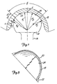
- Figure 1 is a broken-away schematic view in partial cross section of the articulating surfaces of a ball and cup joint prosthesis of the invention with the cup member shown in cross-section;
- Figure 2 is a perspective broken-away view of a hip prosthesis embodying a ball and cup joint prosthesis of the invention;
- Figure 3 is a side view, in partial cross-section, of the cup portion of a prosthesis of the invention; and
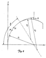
- Figure 4 is a schematic view of surfaces of a ball and cup joint prosthesis of the invention.
-
- "Intimate contact area" means the sliding area of the hard articulating surfaces of the cup and ball in which R1 differs from R3 by no more than 50 micrometers, desirably by no more that 25 micrometers, preferably by no more than six micrometers, and most preferably by no more than two micrometers. On a microscopic level, any metal, ceramic, or other hard surface is somewhat rough and jagged, the surface having peaks and valleys. Reference is made to Mummery, L., Surface Texture Analysis The Handbook, Hommelwerke GmbH, 1992.
Preferably, the centerline average surface roughness of the articulating surfaces in the area of intimate contact is not greater than 0.1 micrometers and preferably not greater than 0.025 micrometers. - Referring first to Figure 2, the proximal portion of the human femur is shown at "F", and the adjacent acetabulum of the pelvis is shown as "B". As shown, a
femoral prosthesis 10 is implanted in the proximal end of the intermedullary canal of the femur by well known surgical procedures, the femoral prosthesis comprising astem 12 that is received in the intermedullary canal and an articulatingball 14 joined to thestem 12 by a connector such as the connectingneck 16, the neck positioning the ball at an angle to the axis of the femur to enable it to articulate in the cup. Shown at 18 in Figures 2 and 3 is an acetabular cup prosthesis which is implanted in the acetabulum by any of a number of similarly well known surgical procedures. - The surgical procedures employed in anchoring a femoral prosthesis and an acetabular cup prosthesis in the proximal end of the femur and in the acetabulum, respectively, have been widely reported. Commonly, the bony acetabulum is exposed and is surgically sculpted to receive a cup prosthesis such as that shown at 18 in Figure 3. The cup prosthesis may be provided with an
outer convex surface 20 that is appropriately roughened or otherwise treated so as to promote good adhesion to bone cement or to promote ingrowth of bony tissue in the event that cement is not employed. Screws or other attachments may be employed to more securely anchor the cup to the acetabulum. In Figure 3, fins 22 are positioned on the outer rim of the cup and become embedded in the hard bony rim of the acetabulum as the cup is forced into place. As mentioned above, bone cement commonly is employed to anchor the cup to the bony acetabulum. - The cup shown in Figure 3 is depicted as being of metal and having a metallic inner articulating
surface 24. However, the cup may consist of several elements. For example, an outer shell similar to that shown in Figure 3 may be provided for attachment to the bony acetabulum, and an inner generally hemispheric shell may be carried by the outer shell, the inner shell having a concave, generally spheroidal hard articulating surface. - Referring to the
femoral prosthesis 10 of Figure 2, the intermedullary canal "C" of the femur commonly is surgically prepared to receive thestem 12 of the prosthesis, and the stem may be either cemented in place using typical bone cement or may be provided with an exterior surface which is tightly received in the intermedullary canal and which promotes and supports bone growth. Theball 14 is attached by means of theneck 16 to the stem and is provided with a hard outer surface 25 (Figure 1) which is carefully formed and configured to articulate with the interior hard articulatingsurface 24 of the cup. The invention relates to the nature of the articulating interaction between the spheroidal articulating hard surfaces of the ball and cup, and it is to this interaction that we now turn. - Referring now to Figure 1, the
ball 14 andcup 18 are shown in articulating contact with one another, and it will be understood that the differences in curvatures of the confronting surfaces of the ball and cup in this figure and also in Figure 4 have been exaggerated for ease of understanding. The area of contact within the solid angle is referred to herein as the "area of intimate contact", and within this area, the surface of the cup is formed on radius R, and the surface of the ball is formed on radius R3. Beyond the area of intimate contact, the surfaces of the ball and cup diverge. Immediately adjacent the area of intimate contact, the radius of the ball is indicated as R2 and the radius of the cup as R4. - Within the area of intimate contact, R1 differs from R3 by no more than 50 micrometers, desirably by no more than 25 micrometers, preferably by no more than 6 micrometers, and most preferably by no more than 2 micrometers. The area of contact subtended by the solid angle ranges from 0.12πR3 2 to 1.65πR3 2, and preferably from 0.2πR3 2 to 0.7πR3 2, as measured when the ball is gently received within the cup (that is, without significant compressive loading between the ball and cup). As discussed in greater detail below, the articulating surfaces of the ball and cup desirably have certain maximum surface roughnesses, and it will be understood that the radii R1, R2, R3 and R4 are measured to the surfaces of the ball and cup as defined by the tips of the surface asperities as measured by a standard coordinate measuring device such as a Sheffield-Bendix Formax model 6060 instrument using a 1.6 mm carbide ball as a probe tip. Such an area of intimate contact would not exist in a conventional metal-to-metal ball and cup prosthesis with the radius of curvature of the ball slightly smaller than that of the cup. As mentioned previously, with conventional metal-to-metal prostheses, high initial wear occurs, and a zone develops in which the surfaces fit with some snugness and have about the same radii of curvature, the zone being bounded by ridges. By providing an area of intimate contact as described herein, such initial wear largely can be avoided. With conventional metal- to-metal implants, most of the wear occurs in the first year or two following implantation. By largely avoiding this initial wear, we may reduce the total wear significantly over the life of the implant.
- For ease of understanding, the area of intimate contact shown in Figure 1 has its center at the apex A of the ball and cup. From Figure 2, it will be understood that the actual compressive load axis between the ball and cup does not necessarily pass through the apexes of the ball and cup, but instead is inclined from the vertical (assuming a standing position) by an angle A ranging from about 15° to about 35°. It is important that the area of intimate contact as described and defined above be intersected by the load axis through all normal movements of the femur with respect to the pelvis. The area of intimate contact is shown in Figure 1 as extending through the angle uniformly about the surface of the ball. Desirably, the angle is large enough to accommodate various alignments of the ball and cup and the position of the load axis so that the latter passes through the area of intimate contact. It may be desirable to shift the axis extending through the center of the area of intimate contact slightly away from the apex of the ball or cup or both so that the area of intimate contact is not symmetric about the apex of the ball or cup but rather is oriented to better contain the shifting load axis.
- The articulating hard surfaces of the ball and socket each preferably are made from a hard metal such as cobalt-chrome alloys. Metals such as titanium and titanium alloys preferably are avoided because of their low galling resistance. Ceramic materials also may be used. References herein to "hard" surfaces should be understood to refer to surfaces having surface hardness values not less than about 170 Knoop. The Knoop hardness number results from the quotient: load applied to a pyramid body/indentation area. The articulating surfaces may be carefully shaped by known superfinishing grinding or lapping processes. Articulating metal surfaces may be hardened by known methods including ion bombardment and the like. Polishing of the resulting surfaces can be done in the usual fashion with a superfinishing machine using a very fine abrasive, care being taken to preserve the congruency of the articulating surfaces of the ball and cup. The shaped surfaces may also be coated with a hard coating such as a diamond-like coating or with a nitride such as titanium nitride. When the articulating surfaces are of metal, it is preferred to employ different metals, or different alloys of similar metals, for the respective surfaces, with the result that the levels of wear resistance of the two materials are different. For example, the surface of the ball may be of a low carbon cobalt-chrome alloy and the surface of the cup of a high carbon cobalt-chrome alloy.
- Also important to the present invention is the nature of the confronting surfaces of the ball and cup in the area immediately adjacent the area of intimate contact. In this area, referred to herein as a "non contact" area, the radius on which the surface of the ball is formed is slightly less than that of the cup. It is desired that the surfaces of the cup and ball diverge from one another gradually in this non-contact area, and it is believed that the very gradual divergence of these surfaces contributes to the ease with which synovial fluid is received between the cup and ball surfaces in the area of intimate contact and to permit the avoidance of ridges which could contribute to increased wear.
- Figure 1 depicts the interior of the cup as being spherical and the ball being formed on the same radius as the cup at the center of the area of intimate contact and a smaller radius toward its equator, and this is the preferred embodiment. The ball may be made spherical instead, and its surface may be formed on the same radius as the cup at the center of the area of intimate contact and may be formed on a larger radius outside the area of intimate contact as the equator is approached. For that matter, outside the area of intimate contact, the radius of the ball may be decreased to a smaller value and the radius of the cup may be increase to a larger value as the equator is approached, so long as the relationship between the gap and the angle is substantially as described above. In the latter case, distance s would be located on the arc swept out by the radius R1, and would lie between the confronting surfaces of the ball and cup. In any event, in order to better avoid the formation of ridges adjacent the area of intimate contact, the radii R2 and R4 each preferably has its origin along a line passing through both the origin of the radius R, and the edge of the area of intimate contact.
- When, as in Figure 1, the interior surface of the cup is spherical (R1 = R4) and the surface of the ball outside the area of intimate contact is formed on a lesser radius, the gap "h" between confronting surfaces of the ball and cup at a distance s from the edge of the area of intimate contact measured along the arc swept out by the radius R1; that is, along the curved surface of the cup away from its apex, is within 20% of the value given by the expression s2/2R in which the effective radius R = (R4R2)/(R4 - R2) where R2 and R4 are the radii of the ball and of the cup, respectively, immediately adjacent the area of intimate contact. Phrased another way, for a given position on the surface of the cup spaced from the area of intimate contact by the angle (as shown in Figure 1) as the angle swept out by the radius R1 away from the area of intimate contact, the gap h is within 20% of the value of the approximate expression (R1)2/2R in which R is as defined above. When is less than about 0.5 radians, the expression (R1)2/2R defines the gap h within plus or minus 3%.
- Similarly, when the exterior surface of the ball is spherical (R2 = R3) and the surface of the cup outside the area of intimate contact is formed on a larger radius, the gap h between confronting surfaces of the ball and cup at a distance s from the edge of the area of intimate contact measured along the arc swept out by the radius R3, that is, along the curved surface of the ball away from its apex is within 20% of the value given by the expression s2/2R in which R is as given above. Phrased another way, for a given position on the surface of the cup spaced from the area of intimate contact by the angle (as shown in Figure 1) as the angle swept out by the radius R3 away from the area of intimate contact, the gap h is within 20% of the value of the approximate expression (R3)2/2R in which R is as defined above and is expressed in radians. When is less than about 0.5 radians, the expression (R3)2/2R defines the gap h within plus or minus 3%.
- Since, in the area of intimate contact, R1 and R3 are essentially equal, the expressions (R3)2/2R and (R1)2/2R are essentially equivalent and can be represented by the latter expression. Although this expression is not precise, it closely approximates the gap h measured along a line extending through the origin of R1 and the confronting surfaces of the ball and cup, and is useful not only when R1 = R4 or R2 = R3, but also when neither of these expressions apply, that is, when the surfaces of the cup and ball outside the area of intimate contact are formed on radii different from the cup and ball radii within the area of intimate contact.
- Thus, it should be understood that the confronting surfaces of the ball and cup diverge quite gradually away from the area of intimate contact, and ridges on the cup or ball are avoided. The nature of the surfaces in the area of intimate contact is such that the surfaces slide over one another with a small amount of wear distributed over the area of intimate contact. It is beneficial to have a large, well lubricated area of intimate contact.
The rate at which the surfaces diverge outside of the area of intimate contact is a function of the effective radius R, as given above. R desirably is in the range of 1 to 14 meters, and preferably in the range of 3 to 10 meters. - Figure 4 illustrates articulating surfaces of a cup and ball in the situation where the surfaces of the cup and ball outside the area of intimate contact are formed on radii different from the cup and ball radii within the area of intimate contact, positions on the cup and ball being located in an X-Y coordinate system having its origin at the center of the area of intimate contact with the X axis perpendicular to the contacting surfaces of the ball and cup at the center of the area on intimate contact. Here, the gap "g" is measured at any given value of X in the non contact area, that is, parallel to the Y axis, and is given by the expression
- Surface roughness of the articulating surfaces also has an influence on wear. The centerline average surface roughness of both the ball and cup articulating surfaces, as measured by a profile measuring machine such as a Sheffield profilometer, is not greater than 0.1 micrometers and preferably is not greater than 0.025 micrometers. With ceramic materials, a surface roughness of 0.0125 micrometers or less may be obtained and is preferred. As with any metal surface, the articulating surfaces of the ball and cup consist of a series of peaks and valleys when viewed at a microscopic level, and when microscopically rough surfaces rub against one another, some wear will occur as the peaks of the respective surfaces encounter one another. In accordance with the present invention, however, it is not enough that the respective articulating surfaces have smooth surfaces. It is also required that the area of intimate contact of these surfaces be in the range of 0.12πR3 2 to 1.65πR3 2. Desirably, the confronting surfaces of the cup and ball adjacent the area of intimate contact diverge in a ridge-free and gradual manner so as to promote lubricant entrainment.
- As a result of the invention, the articulating hard surfaces of the ball and cup joint wear very little, thereby releasing little in the way of harmful debris into the joint space.
- While a preferred embodiment of the present invention has been described, it should be understood that various changes, adaptations and modifications may be made therein without departing from the scope of the appended claims.
Claims (14)
- An articulating joint prosthesis for use between two normally articulating bones, comprising:characterised in that R1 differs from R3 by no more than 50 micrometers, and in that the respective first and second articulating surfaces are configured so that the area of intimate contact ranges from 0.12πR3 2 to 1.65 π R3 2.an articulating cup member (18) attachable to one of the bones and comprising a body having a generally hemispheric cavity provided with a spheroidal internal surface including a first spheroidal articulating surface formed on a radius R1, the surface hardness value being not less than 170 Knoop,an articulating ball member (14) attachable to the other of the bones and having a generally ball-shaped body provided with a spheroidal surface including a second spheroidal articulating surface formed on a radius R3, the surface hardness value being not less than 170 Knoop, and slidingly contacting the first articulating surface in an area of intimate contact
- The articulating joint prosthesis of Claim 1, wherein the respective first and second spheroidal surfaces are configured so that the area of intimate contact ranges from 0.2πR3 2 to 0.7π R3 2.
- An articulating joint prosthesis according to Claim 1 or Claim 2, in which the ball (14) and cup (18) include gradually diverging surfaces outside the area of intimate contact formed respectively on radii R2 and R4, and in which the respective first and second spheroidal surfaces diverging gradually immediately adjacent the area of intimate contact provide a non contact area between the spheroidal surfaces are characterized by the relationship at a position X
- The articulating joint prosthesis of Claim 1 or Claim 2, wherein respective first and second spheroidal surfaces diverge immediately adjacent the area of intimate contact to provide a closely spaced but non contact area between the spheroidal surfaces, the configuration of the surfaces in the non contact area being characterized by the relationship h = (R1)2/2R ± 20% in which h is the gap between the diverging surfaces at a location spaced away from the area of intimate contact by the angle swept out by the radius R3, and R = (R4R2)/R4-R2) where R2 and R4 are the radii of the spheroidal surfaces of the ball and cup, respectively, immediately adjacent the area of intimate contact.
- The prosthesis of Claim 3 or Claim 4, wherein R2 is smaller than R3.
- The prosthesis of Claim 3 or Claim 4, wherein R4 is greater than R1.
- The prosthesis of Claim 3 or Claim 4, wherein R1 = R4.
- The prosthesis of Claim 3 or Claim 4, wherein R2 = R3.
- The prosthesis of any one of the preceding claims, wherein the first and second articulating surfaces in the area of intimate contact are each characterized by a centerline average surface roughness of not greater than 0.1 micrometers.
- The prosthesis of Claim 9, wherein the first and second articulating surfaces in the area of intimate contact are each characterized by a centerline average surface roughness of not greater than 0.025 micrometers.
- The prosthesis of any one of the preceding claims, wherein one of the articulating surfaces of the ball or cup is formed on a constant radius both within and outside the area of intimate contact and the other surface is not.
- The prosthesis of Claim 4 wherein R, in meters, ranges from 1 to 14.
- The prosthesis of Claim 4 or any claim dependent thereon, wherein the configuration of the surfaces in the non contact area at a location spaced away from the area of intimate contact by said angle where is less than 0.5 radians is characterized by the relationship h = (R1)2/2R ± 3%.
- The prosthesis of Claim 4 or any claim dependent thereon, wherein the surfaces in the non contact area at a position X are characterized by the relationship
Applications Claiming Priority (3)
| Application Number | Priority Date | Filing Date | Title |
|---|---|---|---|
| US617295P | 1995-11-02 | 1995-11-02 | |
| US617P | 1995-11-02 | ||
| PCT/US1996/017371 WO1997016138A1 (en) | 1995-11-02 | 1996-11-01 | Low-wear ball and cup joint prosthesis |
Publications (2)
| Publication Number | Publication Date |
|---|---|
| EP0862395A1 EP0862395A1 (en) | 1998-09-09 |
| EP0862395B1 true EP0862395B1 (en) | 2004-04-07 |
Family
ID=21719648
Family Applications (1)
| Application Number | Title | Priority Date | Filing Date |
|---|---|---|---|
| EP96938674A Expired - Lifetime EP0862395B1 (en) | 1995-11-02 | 1996-11-01 | Low-wear ball and cup joint prosthesis |
Country Status (5)
| Country | Link |
|---|---|
| US (1) | US6059830A (en) |
| EP (1) | EP0862395B1 (en) |
| JP (1) | JP2000512164A (en) |
| DE (1) | DE69632145T2 (en) |
| WO (1) | WO1997016138A1 (en) |
Cited By (8)
| Publication number | Priority date | Publication date | Assignee | Title |
|---|---|---|---|---|
| US7273655B2 (en) | 1999-04-09 | 2007-09-25 | Shojiro Miyake | Slidably movable member and method of producing same |
| US7650976B2 (en) | 2003-08-22 | 2010-01-26 | Nissan Motor Co., Ltd. | Low-friction sliding member in transmission, and transmission oil therefor |
| US7771821B2 (en) | 2003-08-21 | 2010-08-10 | Nissan Motor Co., Ltd. | Low-friction sliding member and low-friction sliding mechanism using same |
| US8096205B2 (en) | 2003-07-31 | 2012-01-17 | Nissan Motor Co., Ltd. | Gear |
| US8152377B2 (en) * | 2002-11-06 | 2012-04-10 | Nissan Motor Co., Ltd. | Low-friction sliding mechanism |
| US8206035B2 (en) | 2003-08-06 | 2012-06-26 | Nissan Motor Co., Ltd. | Low-friction sliding mechanism, low-friction agent composition and method of friction reduction |
| US8575076B2 (en) | 2003-08-08 | 2013-11-05 | Nissan Motor Co., Ltd. | Sliding member and production process thereof |
| DE102007031672B4 (en) | 2006-08-04 | 2018-07-26 | Ceramtec Gmbh | Ball head with flats to prevent dry running of an artificial hip joint |
Families Citing this family (56)
| Publication number | Priority date | Publication date | Assignee | Title |
|---|---|---|---|---|
| CA2251334C (en) * | 1996-04-12 | 2003-07-29 | Sulzer Orthopadie Ag | Artificial joint, in particular an artificial hip joint |
| GB9623540D0 (en) * | 1996-11-12 | 1997-01-08 | Johnson & Johnson Professional | Hip joint prosthesis |
| US5928285A (en) * | 1997-05-30 | 1999-07-27 | Bristol-Myers Squibb Co. | Orthopaedic implant having an articulating surface with a conforming and translational surface |
| DE19731442A1 (en) | 1997-07-22 | 1999-02-11 | Plus Endoprothetik Ag | Cup for a joint endoprosthesis |
| CH692650A5 (en) * | 1998-02-26 | 2002-09-13 | Intraplant Ag | The outer shell of a hip endoprosthesis. |
| AU755807B2 (en) * | 1998-11-05 | 2002-12-19 | Louis U. Bigliani | Orthopaedic implant having an articulating surface with a conforming and translational surface |
| EP1000691A3 (en) * | 1998-11-16 | 2002-07-03 | Johnson & Johnson Professional, Inc. | Super finishing of polymeric implant components |
| US6626947B2 (en) * | 2000-10-03 | 2003-09-30 | Depuy Orthopaedics, Inc. | Press fit acetabular cup and associated method for securing the cup to an acetabulum |
| GB0029318D0 (en) | 2000-12-01 | 2001-01-17 | Depuy Int Ltd | An orthopaedic joint prosthesis |
| US7326253B2 (en) | 2001-11-16 | 2008-02-05 | Depuy Products, Inc. | Prosthetic cup assembly having increased assembly congruency |
| FR2832922B1 (en) * | 2001-12-04 | 2004-08-27 | Jean Claude Bouvet | SHOULDER PROSTHESIS |
| US6660040B2 (en) * | 2001-12-19 | 2003-12-09 | Depuy Orthopaedics, Inc. | Prosthetic joints having reduced area bearing surfaces and application thereof to a range of sizes of prosthetic joints |
| GB0200993D0 (en) | 2002-01-17 | 2002-03-06 | Depuy Int Ltd | Manufacturing a component with a near spherical surface |
| GB0207170D0 (en) * | 2002-03-26 | 2002-05-08 | Mcminn Derek J W | Hip joint prosthesis |
| US6911100B1 (en) | 2002-08-30 | 2005-06-28 | Biomet, Inc. | Method for controlling residual stress in prosthetics |
| US7252684B2 (en) * | 2002-11-06 | 2007-08-07 | Southwest Research Institute | Ceramic in replacement components |
| US20040148033A1 (en) * | 2003-01-24 | 2004-07-29 | Schroeder David Wayne | Wear surface for metal-on-metal articulation |
| US7520947B2 (en) | 2003-05-23 | 2009-04-21 | Ati Properties, Inc. | Cobalt alloys, methods of making cobalt alloys, and implants and articles of manufacture made therefrom |
| EP1482190B1 (en) * | 2003-05-27 | 2012-12-05 | Nissan Motor Company Limited | Rolling element |
| JP2005054617A (en) * | 2003-08-08 | 2005-03-03 | Nissan Motor Co Ltd | Valve system |
| US20050261776A1 (en) * | 2004-05-19 | 2005-11-24 | Howmedica Osteonics Corp. | Prosthetic joint with annular contact bearing surface |
| US7473278B2 (en) | 2004-09-16 | 2009-01-06 | Smith & Nephew, Inc. | Method of surface oxidizing zirconium and zirconium alloys and resulting product |
| US7361194B2 (en) * | 2004-10-14 | 2008-04-22 | Wright Medical Technology, Inc. | Metallic bearings for joint replacement |
| US7160329B2 (en) * | 2004-12-01 | 2007-01-09 | Mayo Foundation For Medical Research And Education | Radial-capitellar implant |
| GB0519490D0 (en) * | 2005-09-23 | 2005-11-02 | Benoist Girard Sas | Prosthetic joints |
| ES2606666T3 (en) | 2005-12-15 | 2017-03-27 | Smith & Nephew, Inc. | Medical implant hardened by diffusion |
| US9775713B2 (en) | 2006-01-18 | 2017-10-03 | Smith & Nephew, Inc. | Applications of diffusion hardening techniques |
| US8795441B2 (en) * | 2006-04-26 | 2014-08-05 | Smith & Nephew, Inc. | Reworking of surface oxidized and nitrided components |
| FR2904930B1 (en) * | 2006-08-18 | 2012-08-17 | Advanced Technical Fabrication | COTYLE WITH DOUBLE MOBILITY WITH ANTI-WEAR MEANS |
| US7914580B2 (en) * | 2006-11-07 | 2011-03-29 | Biomedflex Llc | Prosthetic ball-and-socket joint |
| US20110166671A1 (en) * | 2006-11-07 | 2011-07-07 | Kellar Franz W | Prosthetic joint |
| US8029574B2 (en) * | 2006-11-07 | 2011-10-04 | Biomedflex Llc | Prosthetic knee joint |
| US8512413B2 (en) | 2006-11-07 | 2013-08-20 | Biomedflex, Llc | Prosthetic knee joint |
| US8308812B2 (en) | 2006-11-07 | 2012-11-13 | Biomedflex, Llc | Prosthetic joint assembly and joint member therefor |
| US9005306B2 (en) * | 2006-11-07 | 2015-04-14 | Biomedflex, Llc | Medical Implants With Compliant Wear-Resistant Surfaces |
| US8070823B2 (en) * | 2006-11-07 | 2011-12-06 | Biomedflex Llc | Prosthetic ball-and-socket joint |
| US9005307B2 (en) | 2006-11-07 | 2015-04-14 | Biomedflex, Llc | Prosthetic ball-and-socket joint |
| US7905919B2 (en) * | 2006-11-07 | 2011-03-15 | Biomedflex Llc | Prosthetic joint |
| ES2609389T3 (en) * | 2006-11-17 | 2017-04-20 | Scyon Orthopaedics Ag | Geometry to reduce joint wear in total joint replacements |
| US8029573B2 (en) | 2006-12-07 | 2011-10-04 | Ihip Surgical, Llc | Method and apparatus for total hip replacement |
| US8974540B2 (en) | 2006-12-07 | 2015-03-10 | Ihip Surgical, Llc | Method and apparatus for attachment in a modular hip replacement or fracture fixation device |
| US8579985B2 (en) | 2006-12-07 | 2013-11-12 | Ihip Surgical, Llc | Method and apparatus for hip replacement |
| US8715364B2 (en) * | 2007-02-05 | 2014-05-06 | DePuy Synthes Products, LLC | Aspheric hip bearing couple |
| EP2114311A2 (en) * | 2007-02-10 | 2009-11-11 | Small Bone Innovations, Inc. | Radial head implant and related instrument |
| US7985262B2 (en) | 2007-12-28 | 2011-07-26 | Depuy Products, Inc. | Aspheric hip bearing couple |
| US8361381B2 (en) * | 2008-09-25 | 2013-01-29 | Smith & Nephew, Inc. | Medical implants having a porous coated surface |
| GB0901795D0 (en) * | 2009-02-04 | 2009-03-11 | Smith & Nephew | Medical device and method |
| US9545311B2 (en) | 2009-03-05 | 2017-01-17 | Tornier, Inc. | Glenoid implant anchor post |
| EP3170478A1 (en) * | 2009-07-10 | 2017-05-24 | Kirk Promotion LTD. | Hip joint device |
| JP5398468B2 (en) * | 2009-10-21 | 2014-01-29 | 国立大学法人 東京大学 | Artificial hip joint liner and artificial hip joint using the same |
| WO2011146509A2 (en) * | 2010-05-17 | 2011-11-24 | Smith & Nephew Inc. | Liner deformation compensation in an acetabular assembly |
| EP2900179A4 (en) * | 2012-09-27 | 2016-12-21 | The General Hospital Corp D/B/A Massachusetts General Hospital | Femoral heads, mobile inserts, acetabular components, and modular junctions for orthopedic implants and methods of using femoral heads, mobile inserts, acetabular components, and modular junctions for orthopedic implants |
| US10456262B2 (en) | 2016-08-02 | 2019-10-29 | Howmedica Osteonics Corp. | Patient-specific implant flanges with bone side porous ridges |
| CN106580521B (en) * | 2017-01-10 | 2018-04-13 | 李国安 | A kind of composite head artificial hip joint |
| EP3777776A1 (en) * | 2019-08-13 | 2021-02-17 | Alessandro Melozzi | Hip prosthesis head |
| WO2023028588A2 (en) * | 2021-08-26 | 2023-03-02 | Orthopediatrics Corp. | Guided growth spinal implants |
Family Cites Families (11)
| Publication number | Priority date | Publication date | Assignee | Title |
|---|---|---|---|---|
| CH449173A4 (en) * | 1966-09-02 | 1968-04-11 | ||
| US3510883A (en) * | 1967-10-30 | 1970-05-12 | Robert F Cathcart | Joint prosthesis |
| FR2134170B1 (en) * | 1971-04-23 | 1974-03-08 | Benoist Girard & Cie | |
| CH593054A5 (en) * | 1975-06-18 | 1977-11-15 | Sulzer Ag | |
| US4840632A (en) * | 1984-03-16 | 1989-06-20 | Kampner Stanley L | Hip prosthesis |
| CH667988A5 (en) * | 1985-11-18 | 1988-11-30 | Sulzer Ag | ARTIFICIAL HIP PAN. |
| AT386948B (en) * | 1987-07-09 | 1988-11-10 | Menschik Alfred Dr | ARTIFICIAL HIP JOINT |
| CA2133718A1 (en) * | 1993-10-18 | 1995-04-19 | Gene M. Farling | Non-spherical acetabular cup for total hip replacement |
| CA2142634C (en) * | 1994-02-18 | 2005-09-20 | Salvatore Caldarise | Self-lubricating implantable articulation member |
| GB9404077D0 (en) * | 1994-03-03 | 1994-04-20 | Univ Leeds | Acetabular cup |
| US5609643A (en) * | 1995-03-13 | 1997-03-11 | Johnson & Johnson Professional, Inc. | Knee joint prosthesis |
-
1996
- 1996-11-01 WO PCT/US1996/017371 patent/WO1997016138A1/en active IP Right Grant
- 1996-11-01 US US09/066,389 patent/US6059830A/en not_active Expired - Lifetime
- 1996-11-01 EP EP96938674A patent/EP0862395B1/en not_active Expired - Lifetime
- 1996-11-01 DE DE69632145T patent/DE69632145T2/en not_active Expired - Lifetime
- 1996-11-01 JP JP09517500A patent/JP2000512164A/en not_active Ceased
Cited By (8)
| Publication number | Priority date | Publication date | Assignee | Title |
|---|---|---|---|---|
| US7273655B2 (en) | 1999-04-09 | 2007-09-25 | Shojiro Miyake | Slidably movable member and method of producing same |
| US8152377B2 (en) * | 2002-11-06 | 2012-04-10 | Nissan Motor Co., Ltd. | Low-friction sliding mechanism |
| US8096205B2 (en) | 2003-07-31 | 2012-01-17 | Nissan Motor Co., Ltd. | Gear |
| US8206035B2 (en) | 2003-08-06 | 2012-06-26 | Nissan Motor Co., Ltd. | Low-friction sliding mechanism, low-friction agent composition and method of friction reduction |
| US8575076B2 (en) | 2003-08-08 | 2013-11-05 | Nissan Motor Co., Ltd. | Sliding member and production process thereof |
| US7771821B2 (en) | 2003-08-21 | 2010-08-10 | Nissan Motor Co., Ltd. | Low-friction sliding member and low-friction sliding mechanism using same |
| US7650976B2 (en) | 2003-08-22 | 2010-01-26 | Nissan Motor Co., Ltd. | Low-friction sliding member in transmission, and transmission oil therefor |
| DE102007031672B4 (en) | 2006-08-04 | 2018-07-26 | Ceramtec Gmbh | Ball head with flats to prevent dry running of an artificial hip joint |
Also Published As
| Publication number | Publication date |
|---|---|
| US6059830A (en) | 2000-05-09 |
| EP0862395A1 (en) | 1998-09-09 |
| JP2000512164A (en) | 2000-09-19 |
| WO1997016138A1 (en) | 1997-05-09 |
| DE69632145T2 (en) | 2004-08-26 |
| DE69632145D1 (en) | 2004-05-13 |
Similar Documents
| Publication | Publication Date | Title |
|---|---|---|
| EP0862395B1 (en) | Low-wear ball and cup joint prosthesis | |
| WO1997016138A9 (en) | Low-wear ball and cup joint prosthesis | |
| US5593445A (en) | Bi-axial prosthetic joint | |
| US20210338437A1 (en) | Partial hip prosthesis | |
| US6096084A (en) | Modular ball and socket joint preferably with a ceramic head ball | |
| AU2002220859B2 (en) | An orthopaedic joint prosthesis | |
| EP0747025B1 (en) | Low wear artificial spinal disc | |
| EP1212013B1 (en) | Combination of material for joint prosthesis | |
| Schmalzried et al. | Long-duration metal-on-metal total hip arthroplasties with low wear of the articulating surfaces | |
| US9308100B2 (en) | Intervertebral disc prosthesis with a motion-adapted edge for the lumbar and cervical spine | |
| US3922726A (en) | Joint prosthesis | |
| US10245150B2 (en) | Method of implanting aspheric hip bearing couple | |
| EP1611869B1 (en) | Extended radius prosthesis | |
| EP0546162A1 (en) | Non-constrained total joint system. | |
| JPH10248917A (en) | Artificial joint | |
| AU2002220859A1 (en) | An orthopaedic joint prosthesis | |
| US20050033442A1 (en) | Combination of material for joint prothesis | |
| US9655725B2 (en) | Wear-reducing ring for articulations in total joint replacements | |
| WO2006030392A1 (en) | Joint prosthesis component | |
| CN109662808A (en) | A kind of hip prosthesis | |
| GB2246957A (en) | Artificial hip joint |
Legal Events
| Date | Code | Title | Description |
|---|---|---|---|
| PUAI | Public reference made under article 153(3) epc to a published international application that has entered the european phase |
Free format text: ORIGINAL CODE: 0009012 |
|
| AK | Designated contracting states |
Kind code of ref document: A1 Designated state(s): BE DE DK ES FI FR GB GR IE IT LU NL PT SE |
|
| 17P | Request for examination filed |
Effective date: 19980501 |
|
| 17Q | First examination report despatched |
Effective date: 20021219 |
|
| GRAP | Despatch of communication of intention to grant a patent |
Free format text: ORIGINAL CODE: EPIDOSNIGR1 |
|
| GRAS | Grant fee paid |
Free format text: ORIGINAL CODE: EPIDOSNIGR3 |
|
| GRAA | (expected) grant |
Free format text: ORIGINAL CODE: 0009210 |
|
| AK | Designated contracting states |
Kind code of ref document: B1 Designated state(s): BE DE DK ES FI FR GB GR IE IT LU NL PT SE |
|
| PG25 | Lapsed in a contracting state [announced via postgrant information from national office to epo] |
Ref country code: NL Free format text: LAPSE BECAUSE OF FAILURE TO SUBMIT A TRANSLATION OF THE DESCRIPTION OR TO PAY THE FEE WITHIN THE PRESCRIBED TIME-LIMIT Effective date: 20040407 Ref country code: IT Free format text: LAPSE BECAUSE OF FAILURE TO SUBMIT A TRANSLATION OF THE DESCRIPTION OR TO PAY THE FEE WITHIN THE PRESCRIBED TIME-LIMIT;WARNING: LAPSES OF ITALIAN PATENTS WITH EFFECTIVE DATE BEFORE 2007 MAY HAVE OCCURRED AT ANY TIME BEFORE 2007. THE CORRECT EFFECTIVE DATE MAY BE DIFFERENT FROM THE ONE RECORDED. Effective date: 20040407 Ref country code: FI Free format text: LAPSE BECAUSE OF FAILURE TO SUBMIT A TRANSLATION OF THE DESCRIPTION OR TO PAY THE FEE WITHIN THE PRESCRIBED TIME-LIMIT Effective date: 20040407 Ref country code: BE Free format text: LAPSE BECAUSE OF FAILURE TO SUBMIT A TRANSLATION OF THE DESCRIPTION OR TO PAY THE FEE WITHIN THE PRESCRIBED TIME-LIMIT Effective date: 20040407 |
|
| REG | Reference to a national code |
Ref country code: GB Ref legal event code: FG4D |
|
| REF | Corresponds to: |
Ref document number: 69632145 Country of ref document: DE Date of ref document: 20040513 Kind code of ref document: P |
|
| REG | Reference to a national code |
Ref country code: IE Ref legal event code: FG4D |
|
| PG25 | Lapsed in a contracting state [announced via postgrant information from national office to epo] |
Ref country code: SE Free format text: LAPSE BECAUSE OF FAILURE TO SUBMIT A TRANSLATION OF THE DESCRIPTION OR TO PAY THE FEE WITHIN THE PRESCRIBED TIME-LIMIT Effective date: 20040707 Ref country code: GR Free format text: LAPSE BECAUSE OF FAILURE TO SUBMIT A TRANSLATION OF THE DESCRIPTION OR TO PAY THE FEE WITHIN THE PRESCRIBED TIME-LIMIT Effective date: 20040707 Ref country code: DK Free format text: LAPSE BECAUSE OF FAILURE TO SUBMIT A TRANSLATION OF THE DESCRIPTION OR TO PAY THE FEE WITHIN THE PRESCRIBED TIME-LIMIT Effective date: 20040707 |
|
| PG25 | Lapsed in a contracting state [announced via postgrant information from national office to epo] |
Ref country code: ES Free format text: LAPSE BECAUSE OF FAILURE TO SUBMIT A TRANSLATION OF THE DESCRIPTION OR TO PAY THE FEE WITHIN THE PRESCRIBED TIME-LIMIT Effective date: 20040718 |
|
| NLV1 | Nl: lapsed or annulled due to failure to fulfill the requirements of art. 29p and 29m of the patents act | ||
| PG25 | Lapsed in a contracting state [announced via postgrant information from national office to epo] |
Ref country code: LU Free format text: LAPSE BECAUSE OF NON-PAYMENT OF DUE FEES Effective date: 20041101 Ref country code: IE Free format text: LAPSE BECAUSE OF NON-PAYMENT OF DUE FEES Effective date: 20041101 |
|
| ET | Fr: translation filed | ||
| PLBE | No opposition filed within time limit |
Free format text: ORIGINAL CODE: 0009261 |
|
| STAA | Information on the status of an ep patent application or granted ep patent |
Free format text: STATUS: NO OPPOSITION FILED WITHIN TIME LIMIT |
|
| 26N | No opposition filed |
Effective date: 20050110 |
|
| REG | Reference to a national code |
Ref country code: IE Ref legal event code: MM4A |
|
| PG25 | Lapsed in a contracting state [announced via postgrant information from national office to epo] |
Ref country code: PT Free format text: LAPSE BECAUSE OF NON-PAYMENT OF DUE FEES Effective date: 20040907 |
|
| REG | Reference to a national code |
Ref country code: DE Ref legal event code: R082 Ref document number: 69632145 Country of ref document: DE Representative=s name: VOSSIUS & PARTNER PATENTANWAELTE RECHTSANWAELT, DE |
|
| REG | Reference to a national code |
Ref country code: DE Ref legal event code: R082 Ref document number: 69632145 Country of ref document: DE Representative=s name: VOSSIUS & PARTNER PATENTANWAELTE RECHTSANWAELT, DE Effective date: 20150225 Ref country code: DE Ref legal event code: R081 Ref document number: 69632145 Country of ref document: DE Owner name: MICROPORT ORTHOPEDICS HOLDINGS INC., NL Free format text: FORMER OWNER: WRIGHT MEDICAL TECHNOLOGY INC., ARLINGTON, TENN., US Effective date: 20150225 |
|
| REG | Reference to a national code |
Ref country code: FR Ref legal event code: TP Owner name: MICORPORT ORTHOPEDICS HOLDINGS INC., NL Effective date: 20150320 |
|
| REG | Reference to a national code |
Ref country code: GB Ref legal event code: 732E Free format text: REGISTERED BETWEEN 20150723 AND 20150729 |
|
| REG | Reference to a national code |
Ref country code: FR Ref legal event code: PLFP Year of fee payment: 20 |
|
| PGFP | Annual fee paid to national office [announced via postgrant information from national office to epo] |
Ref country code: DE Payment date: 20151028 Year of fee payment: 20 Ref country code: GB Payment date: 20151028 Year of fee payment: 20 |
|
| PGFP | Annual fee paid to national office [announced via postgrant information from national office to epo] |
Ref country code: FR Payment date: 20151008 Year of fee payment: 20 |
|
| REG | Reference to a national code |
Ref country code: DE Ref legal event code: R071 Ref document number: 69632145 Country of ref document: DE |
|
| REG | Reference to a national code |
Ref country code: GB Ref legal event code: PE20 Expiry date: 20161031 |
|
| PG25 | Lapsed in a contracting state [announced via postgrant information from national office to epo] |
Ref country code: GB Free format text: LAPSE BECAUSE OF EXPIRATION OF PROTECTION Effective date: 20161031 |