EP0863012A1 - Detection of printhead nozzle functionality by optical scanning of a test pattern - Google Patents
Detection of printhead nozzle functionality by optical scanning of a test pattern Download PDFInfo
- Publication number
- EP0863012A1 EP0863012A1 EP98301571A EP98301571A EP0863012A1 EP 0863012 A1 EP0863012 A1 EP 0863012A1 EP 98301571 A EP98301571 A EP 98301571A EP 98301571 A EP98301571 A EP 98301571A EP 0863012 A1 EP0863012 A1 EP 0863012A1
- Authority
- EP
- European Patent Office
- Prior art keywords
- test pattern
- test
- carriage
- printhead
- nozzles
- Prior art date
- Legal status (The legal status is an assumption and is not a legal conclusion. Google has not performed a legal analysis and makes no representation as to the accuracy of the status listed.)
- Granted
Links
Images


Classifications
-
- B—PERFORMING OPERATIONS; TRANSPORTING
- B41—PRINTING; LINING MACHINES; TYPEWRITERS; STAMPS
- B41J—TYPEWRITERS; SELECTIVE PRINTING MECHANISMS, i.e. MECHANISMS PRINTING OTHERWISE THAN FROM A FORME; CORRECTION OF TYPOGRAPHICAL ERRORS
- B41J2/00—Typewriters or selective printing mechanisms characterised by the printing or marking process for which they are designed
- B41J2/005—Typewriters or selective printing mechanisms characterised by the printing or marking process for which they are designed characterised by bringing liquid or particles selectively into contact with a printing material
- B41J2/01—Ink jet
- B41J2/135—Nozzles
- B41J2/165—Preventing or detecting of nozzle clogging, e.g. cleaning, capping or moistening for nozzles
- B41J2/16579—Detection means therefor, e.g. for nozzle clogging
-
- B—PERFORMING OPERATIONS; TRANSPORTING
- B41—PRINTING; LINING MACHINES; TYPEWRITERS; STAMPS
- B41J—TYPEWRITERS; SELECTIVE PRINTING MECHANISMS, i.e. MECHANISMS PRINTING OTHERWISE THAN FROM A FORME; CORRECTION OF TYPOGRAPHICAL ERRORS
- B41J2/00—Typewriters or selective printing mechanisms characterised by the printing or marking process for which they are designed
- B41J2/005—Typewriters or selective printing mechanisms characterised by the printing or marking process for which they are designed characterised by bringing liquid or particles selectively into contact with a printing material
- B41J2/01—Ink jet
- B41J2/015—Ink jet characterised by the jet generation process
- B41J2/04—Ink jet characterised by the jet generation process generating single droplets or particles on demand
- B41J2/045—Ink jet characterised by the jet generation process generating single droplets or particles on demand by pressure, e.g. electromechanical transducers
- B41J2/04501—Control methods or devices therefor, e.g. driver circuits, control circuits
- B41J2/0451—Control methods or devices therefor, e.g. driver circuits, control circuits for detecting failure, e.g. clogging, malfunctioning actuator
-
- B—PERFORMING OPERATIONS; TRANSPORTING
- B41—PRINTING; LINING MACHINES; TYPEWRITERS; STAMPS
- B41J—TYPEWRITERS; SELECTIVE PRINTING MECHANISMS, i.e. MECHANISMS PRINTING OTHERWISE THAN FROM A FORME; CORRECTION OF TYPOGRAPHICAL ERRORS
- B41J2/00—Typewriters or selective printing mechanisms characterised by the printing or marking process for which they are designed
- B41J2/005—Typewriters or selective printing mechanisms characterised by the printing or marking process for which they are designed characterised by bringing liquid or particles selectively into contact with a printing material
- B41J2/01—Ink jet
- B41J2/015—Ink jet characterised by the jet generation process
- B41J2/04—Ink jet characterised by the jet generation process generating single droplets or particles on demand
- B41J2/045—Ink jet characterised by the jet generation process generating single droplets or particles on demand by pressure, e.g. electromechanical transducers
- B41J2/04501—Control methods or devices therefor, e.g. driver circuits, control circuits
- B41J2/0458—Control methods or devices therefor, e.g. driver circuits, control circuits controlling heads based on heating elements forming bubbles
-
- B—PERFORMING OPERATIONS; TRANSPORTING
- B41—PRINTING; LINING MACHINES; TYPEWRITERS; STAMPS
- B41J—TYPEWRITERS; SELECTIVE PRINTING MECHANISMS, i.e. MECHANISMS PRINTING OTHERWISE THAN FROM A FORME; CORRECTION OF TYPOGRAPHICAL ERRORS
- B41J29/00—Details of, or accessories for, typewriters or selective printing mechanisms not otherwise provided for
- B41J29/38—Drives, motors, controls or automatic cut-off devices for the entire printing mechanism
- B41J29/393—Devices for controlling or analysing the entire machine ; Controlling or analysing mechanical parameters involving printing of test patterns
- B41J2029/3935—Devices for controlling or analysing the entire machine ; Controlling or analysing mechanical parameters involving printing of test patterns by means of printed test patterns
Definitions
- a nozzle detection test pattern has been developed which can be sensed by an optical sensor located on an inkjet printer carriage. By having the same nozzle print ink drops on multiple pixels to form a single thickened test line during multiple passes of the printhead, it is possible to thereafter scan across such test line and automatically determine by the light contrast ratios which nozzles are not firing properly.
- a green light LED is used to illuminate the magenta, cyan and black test patterns as they are being sensed, and a blue light LED is used to illuminate the yellow test pattern as it is being sensed.
- a separate test pattern is used for each printhead ink color. The test pattern constitutes six rows with forty test lines on each row for a printhead having 240 active nozzles.
- the invention provides a method of monitoring and controlling the quality of pen markings on a plotting medium by optically sensing across a sample line drawn on an actual medium.
- a customized optical sensor for monitoring plotter performance by sensing the quality of lines drawn on a medium.
- An LED emitting a green light beam is angularly directed toward an underlying line so as to reflect into an optical sensor which measures the print contrast ratio of a point on the line.
- Circuit means amplifies and filters the signal generated by the optical sensor.
- a green LED is used for sensing sample patterns printed by each of the black (K), cyan (C) and magenta (M) printheads, while a blue LED is used for sensing sample patterns printed by the yellow (Y) printhead.
- a light tube on a carriage-mounted optical sensor has inner walls which help direct light from an LED toward an area surrounding a point under the sensor, and outer walls which help block out undesirable external light from being reflected from the area surrounding a point under the sensor into the photocell.
- the invention contemplates optical sensing of different color markings on media using different color lights, raster "lines” (i. e. bars) printed on a pixel grid by an inkjet printer/plotter.
- FIG. 1 is a perspective view of an inkjet printer/plotter 210 having a housing 212 mounted on a stand 214.
- the housing has left and right drive mechanism enclosures 216 and 218.
- a control panel 220 is mounted on the right enclosure 218.
- a carriage assembly 300 illustrated in phantom under a cover 222, is adapted for reciprocal motion along a carriage bar 224, also shown in phantom.
- the position of the carriage assembly 300 in a horizontal or carriage scan axis is determined by a carriage positioning mechanism 310 with respect to an encoder strip 320 (see FIG. 2).
- a print medium 330 such as paper is positioned along a vertical or media axis by a media axis drive mechanism (not shown).
- the media axis is called the X axis denoted as 201
- the scan axis is called the Y axis denoted as 301.
- FIG. 2 is a perspective view of the carriage assembly 300, the carriage positioning mechanism 310 and the encoder strip 320.
- the carriage positioning mechanism 310 includes a carriage position motor 312 which has a shaft 314 which drives a belt 324 which is secured by idler 326 and which is attached to the carriage 300.
- the position of the carriage assembly in the scan axis is determined precisely by the encoder strip 320.
- the encoder strip 320 is secured by a first stanchion 328 on one end and a second stanchion 329 on the other end.
- An optical reader (not shown) is disposed on the carriage assembly and provides carriage position signals which are utilized by the invention to achieve optimal image registration in the manner described below.
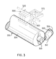
- FIG. 3 is perspective view of a simplified representation of a media positioning system 350 which can be utilised in the inventive printer.
- the media positioning system 350 includes a motor 352 which is normal to and drives a media roller 354.
- the position of the media roller 354 is determined by a media position encoder 356 on the motor.
- An optical reader 360 senses the position of the encoder 356 and provides a plurality of output pulses which indirectly determines the position of the roller 354 and, therefore, the position of the media 230 in the X axis.
- the media and carriage position information is provided to a processor on a circuit board 370 disposed on the carriage assembly 100 for use in connection with printhead alignment techniques of the present invention.
- the printer 210 has four inkjet print cartridges 302, 304, 306, and 308 that store ink of different colors, e.g., black. magenta, cyan and yellow ink, respectively.
- inkjet print cartridges 302, 304, 306, and 308 that store ink of different colors, e.g., black. magenta, cyan and yellow ink, respectively.
- selected nozzles in the inkjet print cartridges 302, 304, 306, and 308 are activated and ink is applies to the medium 230.
- the colors from the three color cartridges are mixed to obtain any other particular color.
- Sample lines 240 are typically printed on the media 230 prior to doing an actual printout in order to allow the optical sensor 400 to pass over and scan across the lines as part of the initial calibration.
- the carriage assembly 300 positions the inkjet print cartridges and holds the circuitry required for interface to the ink firing circuits in the print cartridges.
- the carriage assembly 300 includes a carriage 301 adapted for reciprocal motion on front and rear slider rods 303, 305.
- FIG. 4 shows a presently preferred embodiment of printheads each having two groups of nozzles with a column offset 410.
- the optical sensor 400 is designed for precise positioning of all of its optical components.
- the sensor unit includes a photocell 420, holder 422, cover 424, lens 426, and light source such as two LEDs 428, 430.
- a protective casing 440 which also acts as an ESD shield for sensor components is provided for attachment to the carriage.
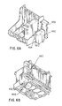
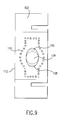
- FIG. 9 An optical sensor unit having increased shielding against ambient light is shown in FIG. 9, including a housing 102, lenses 104, green light LED 106, and blue light LED 108.
- the previous external perimeter of the shielding is shown in dotted lines 110, which the new version of an enlarged shielding 112 provide improved optical performance.
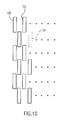
- FIG. 10 shows a preferred arrangement of markings, each group being fired solely by a particular nozzle during successive multiple passes of the printhead across the media.
- a two-pixel advance between bi-directional passes across the media is used to generate the patterns.
- Groups 120, 122 are represented as being somewhat solid in ink drops from two good nozzles, respectively, while group 124 is virtually non-existent thereby indicating a non-firing nozzle.
- FIG. 11 shows a preferred sequence of scanning, with six complete one-way scans being sufficient to pass over 240 separate group markings representing output from two individual nozzles, respectively.
- the green light is used for illumination of the magenta, cyan and black patterns during optical sensing, while a blue light is used for illumination of the yellow pattern (sometimes printed against a cyan background for better contrast). Because the contrast sensed for the yellow test pattern is much weaker than for the other colors, it was found preferable to use a separate stronger amplification circuit for the yellow patterns in order to provide the same performance as with the other color inks.
- FIG. 12 illustrates the layout and detailed specifications for a recent specific implementation of the present invention.
- the patterns have been successfully used with two hundred forty active nozzles on each of four 600 dpi printheads schematically shown in FIG. 13 in their aligned configuration on an inkjet printer carriage.
Abstract
Description
Claims (5)
- Apparatus for detecting nozzle functionality in an inkjet printer, comprising:a scanning carriage with at least one printhead;an optical sensor capable of detecting the presence or absence of ink drops on media;a source of illumination;a test pattern having ink drops from a single nozzle forming a test group; andmeans for moving the optical sensor across said test group to detect non-firing nozzles.
- The apparatus of claim 1 wherein said optical sensor is mounted on said scanning carriage.
- The apparatus of claim 1 wherein said source of illumination is mounted on said scanning carriage.
- The apparatus of claim 1 wherein said source of illumination includes at least two different colored light sources.
- A method of determining nozzle functionality in an inkjet printer having a plurality of different nozzle groups, each group firing a different color ink, comprising the steps of:printing a test pattern from the different nozzle groups, with predetermined portions of the test pattern being printed by different nozzles, respectively;shielding the test pattern from ambient light;illuminating the test pattern with artificial light;optically scanning across the portions of the test pattern during said shielding and illuminating steps to sense which portions have been printed satisfactorily by a particular nozzle.
Applications Claiming Priority (2)
| Application Number | Priority Date | Filing Date | Title |
|---|---|---|---|
| US811412 | 1991-12-20 | ||
| US08/811,412 US6352331B1 (en) | 1997-03-04 | 1997-03-04 | Detection of non-firing printhead nozzles by optical scanning of a test pattern |
Publications (2)
| Publication Number | Publication Date |
|---|---|
| EP0863012A1 true EP0863012A1 (en) | 1998-09-09 |
| EP0863012B1 EP0863012B1 (en) | 2003-01-08 |
Family
ID=25206485
Family Applications (1)
| Application Number | Title | Priority Date | Filing Date |
|---|---|---|---|
| EP98301571A Expired - Lifetime EP0863012B1 (en) | 1997-03-04 | 1998-03-03 | Detection of printhead nozzle functionality by optical scanning of a test pattern |
Country Status (5)
| Country | Link |
|---|---|
| US (1) | US6352331B1 (en) |
| EP (1) | EP0863012B1 (en) |
| JP (1) | JPH10258503A (en) |
| DE (1) | DE69810526T9 (en) |
| ES (1) | ES2186968T3 (en) |
Cited By (13)
| Publication number | Priority date | Publication date | Assignee | Title |
|---|---|---|---|---|
| EP0988990A3 (en) * | 1998-09-22 | 2000-10-11 | Seiren Co., Ltd. | Ink-jet printer nozzle defect detection method and device |
| WO2001002971A1 (en) * | 1999-07-01 | 2001-01-11 | Lexmark International, Inc. | Entry of missing nozzle information in an ink jet printer |
| FR2801836A1 (en) | 1999-12-03 | 2001-06-08 | Imaje Sa | SIMPLIFIED MANUFACTURING PRINTER AND METHOD OF MAKING |
| FR2801835A1 (en) * | 1999-12-03 | 2001-06-08 | Imaje Sa | PROCESS AND PRINTER WITH SUBSTRATE ADVANCE CONTROL |
| EP1176802A2 (en) * | 2000-07-28 | 2002-01-30 | Hewlett Packard Company, a Delaware Corporation | Techniques for measuring the position of marks on media and for aligning inkjet devices |
| WO2002081214A2 (en) * | 2001-04-04 | 2002-10-17 | Aprion Digital Ltd. | A method and system for compensating for banding defects in inkjet printers |
| GB2384931A (en) * | 2002-01-30 | 2003-08-06 | Hewlett Packard Co | Printer incorporating test pattern scanner |
| US6637853B1 (en) * | 1999-07-01 | 2003-10-28 | Lexmark International, Inc. | Faulty nozzle detection in an ink jet printer by printing test patterns and scanning with a fixed optical sensor |
| US7086715B2 (en) * | 2002-12-20 | 2006-08-08 | Brother Kogyo Kabushiki Kaisha | Method of printing a test pattern, an image forming device, and a recording medium on which the test pattern is printed |
| EP1798039A1 (en) | 2005-12-14 | 2007-06-20 | Pitney Bowes, Inc. | System and method for detecting defective ink jet nozzles |
| US7438378B2 (en) | 2004-08-30 | 2008-10-21 | Pitney Bowes Inc. | Fluorescent ink detector |
| CN102259487A (en) * | 2010-05-24 | 2011-11-30 | 佳能株式会社 | Image processor and image processing method |
| EP2391112A1 (en) * | 2010-05-24 | 2011-11-30 | Canon Kabushiki Kaisha | Image processor and image processing method |
Families Citing this family (39)
| Publication number | Priority date | Publication date | Assignee | Title |
|---|---|---|---|---|
| US6565185B1 (en) * | 1999-09-29 | 2003-05-20 | Seiko Epson Corporation | Nozzle testing before and after nozzle cleaning |
| US6752493B2 (en) | 2002-04-30 | 2004-06-22 | Hewlett-Packard Development Company, L.P. | Fluid delivery techniques with improved reliability |
| US6652080B2 (en) | 2002-04-30 | 2003-11-25 | Hewlett-Packard Development Company, Lp. | Re-circulating fluid delivery system |
| JP4507509B2 (en) * | 2002-10-18 | 2010-07-21 | コニカミノルタホールディングス株式会社 | Inkjet recording device |
| US7055925B2 (en) | 2003-07-31 | 2006-06-06 | Hewlett-Packard Development Company, L.P. | Calibration and measurement techniques for printers |
| US7364251B2 (en) * | 2003-08-13 | 2008-04-29 | Konica Minolta Holdings, Inc. | Inkjet recording apparatus and recording medium movement control method |
| TWI274669B (en) * | 2003-11-11 | 2007-03-01 | Ind Tech Res Inst | Method and apparatus for detecting faulty nozzles |
| JP4852232B2 (en) * | 2004-01-09 | 2012-01-11 | ブラザー工業株式会社 | Inkjet recording device |
| US20050225588A1 (en) * | 2004-04-12 | 2005-10-13 | King David G | Method and apparatus for nozzle map memory storage on a printhead |
| US20060139670A1 (en) * | 2004-12-27 | 2006-06-29 | Hoblit Robert S | Method and system for correcting output of printer devices |
| JP4652929B2 (en) * | 2005-08-18 | 2011-03-16 | 船井電機株式会社 | Inkjet printer |
| US7887166B2 (en) * | 2005-09-07 | 2011-02-15 | Retail Inkjet Solutions, Inc. | Ink reservoir |
| KR100871851B1 (en) * | 2005-11-28 | 2008-12-03 | 삼성전자주식회사 | Method and apparatus for detecting a defect nozzle of a wide array head |
| US20070176981A1 (en) | 2006-01-30 | 2007-08-02 | Shahar Turgeman | Ink jet printer cartridge refilling method and apparatus |
| US10144222B1 (en) | 2006-01-30 | 2018-12-04 | Shahar Turgeman | Ink printing system |
| US8403466B1 (en) | 2010-04-02 | 2013-03-26 | Shahar Turgeman | Wide format printer cartridge refilling method and apparatus |
| US8517524B1 (en) | 2006-01-30 | 2013-08-27 | Shahar Turgeman | Ink jet printer cartridge refilling method and apparatus |
| US8960868B1 (en) | 2006-01-30 | 2015-02-24 | Shahar Turgeman | Ink predispense processing and cartridge fill method and apparatus |
| US9718268B1 (en) | 2006-01-30 | 2017-08-01 | Shahar Turgeman | Ink printing system comprising groups of inks, each group having a unique ink base composition |
| US20090153602A1 (en) * | 2007-12-18 | 2009-06-18 | Thomas Daniel Brown | Printing Cartridge Refill Method And Associated Cartridge Refill System |
| JP2009154406A (en) * | 2007-12-27 | 2009-07-16 | Brother Ind Ltd | Inkjet recording apparatus |
| US8376516B2 (en) | 2010-04-06 | 2013-02-19 | Xerox Corporation | System and method for operating a web printing system to compensate for dimensional changes in the web |
| US20110242187A1 (en) * | 2010-04-06 | 2011-10-06 | Xerox Corporation | Test Pattern Effective For Fine Registration Of Inkjet Printheads And Method Of Analysis Of Image Data Corresponding To The Test Pattern In An Inkjet Printer |
| US8602518B2 (en) | 2010-04-06 | 2013-12-10 | Xerox Corporation | Test pattern effective for coarse registration of inkjet printheads and methods of analysis of image data corresponding to the test pattern in an inkjet printer |
| US8585173B2 (en) | 2011-02-14 | 2013-11-19 | Xerox Corporation | Test pattern less perceptible to human observation and method of analysis of image data corresponding to the test pattern in an inkjet printer |
| EP2626209B1 (en) | 2012-02-12 | 2018-04-11 | Baumer Inspection GmbH | Method and device for detecting malfunctions of nozzles of an ink-jet printer |
| JP6016385B2 (en) * | 2012-03-09 | 2016-10-26 | キヤノン株式会社 | Recording device and sensor unit |
| JP6033005B2 (en) * | 2012-03-09 | 2016-11-30 | キヤノン株式会社 | Recording device and sensor unit |
| US11141752B2 (en) | 2012-12-27 | 2021-10-12 | Kateeva, Inc. | Techniques for arrayed printing of a permanent layer with improved speed and accuracy |
| CN107891668B (en) | 2012-12-27 | 2020-04-21 | 科迪华公司 | Apparatus and method for printing ink volume control to deposit fluid within precise tolerances |
| US9700908B2 (en) | 2012-12-27 | 2017-07-11 | Kateeva, Inc. | Techniques for arrayed printing of a permanent layer with improved speed and accuracy |
| US9352561B2 (en) | 2012-12-27 | 2016-05-31 | Kateeva, Inc. | Techniques for print ink droplet measurement and control to deposit fluids within precise tolerances |
| US9832428B2 (en) | 2012-12-27 | 2017-11-28 | Kateeva, Inc. | Fast measurement of droplet parameters in industrial printing system |
| US11673155B2 (en) | 2012-12-27 | 2023-06-13 | Kateeva, Inc. | Techniques for arrayed printing of a permanent layer with improved speed and accuracy |
| US8888225B2 (en) | 2013-04-19 | 2014-11-18 | Xerox Corporation | Method for calibrating optical detector operation with marks formed on a moving image receiving surface in a printer |
| CN107933089B (en) | 2013-12-12 | 2020-08-11 | 科迪华公司 | Method of manufacturing electronic device |
| JP6550901B2 (en) * | 2015-04-30 | 2019-07-31 | ブラザー工業株式会社 | Liquid discharge device |
| JP6903939B2 (en) * | 2017-02-21 | 2021-07-14 | セイコーエプソン株式会社 | How to create test patterns, test patterns, printing devices, programs |
| JP7229782B2 (en) | 2019-01-09 | 2023-02-28 | キヤノン株式会社 | Measuring device and image forming system |
Citations (7)
| Publication number | Priority date | Publication date | Assignee | Title |
|---|---|---|---|---|
| DE3246707A1 (en) * | 1982-12-17 | 1984-06-20 | Olympia Werke Ag, 2940 Wilhelmshaven | Arrangement for testing jet outlet openings on ink print heads for blockage or contamination in ink printing mechanisms |
| EP0348234A2 (en) * | 1988-06-23 | 1989-12-27 | Canon Kabushiki Kaisha | Ink-jet recording apparatus |
| JPH03104678A (en) * | 1989-09-19 | 1991-05-01 | Shimadzu Corp | Printer |
| JPH04169239A (en) * | 1990-11-01 | 1992-06-17 | Mita Ind Co Ltd | Ink-jet record device |
| EP0500281A2 (en) * | 1991-02-20 | 1992-08-26 | Canon Kabushiki Kaisha | Recording apparatus with automatic recovery function |
| JPH0624008A (en) * | 1992-07-09 | 1994-02-01 | Canon Inc | Ink jet recording device |
| EP0622220A2 (en) * | 1993-04-30 | 1994-11-02 | Hewlett-Packard Company | Multiple inkjet cartridge alignment for bidirectional printing by scanning a reference pattern |
Family Cites Families (6)
| Publication number | Priority date | Publication date | Assignee | Title |
|---|---|---|---|---|
| JPS57110455A (en) * | 1980-12-27 | 1982-07-09 | Ricoh Co Ltd | Ink jet printing apparatus |
| JPS58162350A (en) * | 1982-03-23 | 1983-09-27 | Fanuc Ltd | Printer |
| JPS63260448A (en) * | 1987-04-17 | 1988-10-27 | Seiko Epson Corp | Method for detecting injection error in ink jet printer |
| JPH02194955A (en) * | 1989-01-24 | 1990-08-01 | Canon Inc | Ink jet recorder |
| US5109239A (en) * | 1989-01-31 | 1992-04-28 | Hewlett-Packard Company | Inter pen offset determination and compensation in multi-pen ink jet printing systems |
| US5508826A (en) * | 1993-04-27 | 1996-04-16 | Lloyd; William J. | Method and apparatus for calibrated digital printing using a four by four transformation matrix |
-
1997
- 1997-03-04 US US08/811,412 patent/US6352331B1/en not_active Expired - Lifetime
-
1998
- 1998-03-02 JP JP10049475A patent/JPH10258503A/en active Pending
- 1998-03-03 EP EP98301571A patent/EP0863012B1/en not_active Expired - Lifetime
- 1998-03-03 DE DE69810526T patent/DE69810526T9/en not_active Expired - Fee Related
- 1998-03-03 ES ES98301571T patent/ES2186968T3/en not_active Expired - Lifetime
Patent Citations (7)
| Publication number | Priority date | Publication date | Assignee | Title |
|---|---|---|---|---|
| DE3246707A1 (en) * | 1982-12-17 | 1984-06-20 | Olympia Werke Ag, 2940 Wilhelmshaven | Arrangement for testing jet outlet openings on ink print heads for blockage or contamination in ink printing mechanisms |
| EP0348234A2 (en) * | 1988-06-23 | 1989-12-27 | Canon Kabushiki Kaisha | Ink-jet recording apparatus |
| JPH03104678A (en) * | 1989-09-19 | 1991-05-01 | Shimadzu Corp | Printer |
| JPH04169239A (en) * | 1990-11-01 | 1992-06-17 | Mita Ind Co Ltd | Ink-jet record device |
| EP0500281A2 (en) * | 1991-02-20 | 1992-08-26 | Canon Kabushiki Kaisha | Recording apparatus with automatic recovery function |
| JPH0624008A (en) * | 1992-07-09 | 1994-02-01 | Canon Inc | Ink jet recording device |
| EP0622220A2 (en) * | 1993-04-30 | 1994-11-02 | Hewlett-Packard Company | Multiple inkjet cartridge alignment for bidirectional printing by scanning a reference pattern |
Non-Patent Citations (3)
| Title |
|---|
| PATENT ABSTRACTS OF JAPAN vol. 015, no. 290 (M - 1139) 23 July 1991 (1991-07-23) * |
| PATENT ABSTRACTS OF JAPAN vol. 016, no. 471 (M - 1318) 30 September 1992 (1992-09-30) * |
| PATENT ABSTRACTS OF JAPAN vol. 018, no. 229 (M - 1598) 26 April 1994 (1994-04-26) * |
Cited By (27)
| Publication number | Priority date | Publication date | Assignee | Title |
|---|---|---|---|---|
| EP0988990A3 (en) * | 1998-09-22 | 2000-10-11 | Seiren Co., Ltd. | Ink-jet printer nozzle defect detection method and device |
| WO2001002971A1 (en) * | 1999-07-01 | 2001-01-11 | Lexmark International, Inc. | Entry of missing nozzle information in an ink jet printer |
| US6215557B1 (en) | 1999-07-01 | 2001-04-10 | Lexmark International, Inc. | Entry of missing nozzle information in an ink jet printer |
| US6637853B1 (en) * | 1999-07-01 | 2003-10-28 | Lexmark International, Inc. | Faulty nozzle detection in an ink jet printer by printing test patterns and scanning with a fixed optical sensor |
| EP1106370A1 (en) * | 1999-12-03 | 2001-06-13 | Imaje S.A. | Method and printer with substrate advance control |
| EP1106371A1 (en) | 1999-12-03 | 2001-06-13 | Imaje S.A. | Printer with simplified manufacturing and manufacturing method |
| US6398334B2 (en) | 1999-12-03 | 2002-06-04 | Imaje S.A. | Process and printer with substrate advance control |
| US6464322B2 (en) | 1999-12-03 | 2002-10-15 | Imaje S.A. | Ink jet printer and a process for compensating for mechanical defects in the ink jet printer |
| FR2801835A1 (en) * | 1999-12-03 | 2001-06-08 | Imaje Sa | PROCESS AND PRINTER WITH SUBSTRATE ADVANCE CONTROL |
| FR2801836A1 (en) | 1999-12-03 | 2001-06-08 | Imaje Sa | SIMPLIFIED MANUFACTURING PRINTER AND METHOD OF MAKING |
| EP1176802A3 (en) * | 2000-07-28 | 2004-03-03 | Hewlett Packard Company, a Delaware Corporation | Techniques for measuring the position of marks on media and for aligning inkjet devices |
| EP1176802A2 (en) * | 2000-07-28 | 2002-01-30 | Hewlett Packard Company, a Delaware Corporation | Techniques for measuring the position of marks on media and for aligning inkjet devices |
| WO2002081214A2 (en) * | 2001-04-04 | 2002-10-17 | Aprion Digital Ltd. | A method and system for compensating for banding defects in inkjet printers |
| WO2002081214A3 (en) * | 2001-04-04 | 2003-01-09 | Aprion Digital Ltd | A method and system for compensating for banding defects in inkjet printers |
| GB2384931A (en) * | 2002-01-30 | 2003-08-06 | Hewlett Packard Co | Printer incorporating test pattern scanner |
| US6802580B2 (en) | 2002-01-30 | 2004-10-12 | Hewlett-Packard Development Company, L.P. | Printer device and method |
| GB2384931B (en) * | 2002-01-30 | 2005-06-29 | Hewlett Packard Co | Printer device and method |
| US7086715B2 (en) * | 2002-12-20 | 2006-08-08 | Brother Kogyo Kabushiki Kaisha | Method of printing a test pattern, an image forming device, and a recording medium on which the test pattern is printed |
| US7438378B2 (en) | 2004-08-30 | 2008-10-21 | Pitney Bowes Inc. | Fluorescent ink detector |
| EP1798039A1 (en) | 2005-12-14 | 2007-06-20 | Pitney Bowes, Inc. | System and method for detecting defective ink jet nozzles |
| US7878615B2 (en) | 2005-12-14 | 2011-02-01 | Pitney Bowes Inc. | System and method for detecting defective ink jet nozzles |
| CN102259487A (en) * | 2010-05-24 | 2011-11-30 | 佳能株式会社 | Image processor and image processing method |
| EP2391112A1 (en) * | 2010-05-24 | 2011-11-30 | Canon Kabushiki Kaisha | Image processor and image processing method |
| CN102259487B (en) * | 2010-05-24 | 2014-04-16 | 佳能株式会社 | Image processor and image processing method |
| US8743420B2 (en) | 2010-05-24 | 2014-06-03 | Canon Kabushiki Kaisha | Image processor and image processing method |
| US9623671B2 (en) | 2010-05-24 | 2017-04-18 | Canon Kabushiki Kaisha | Image processor, printing apparatus, and image processing method |
| US10022983B2 (en) | 2010-05-24 | 2018-07-17 | Canon Kabushiki Kaisha | Image processor, printing apparatus, and image processing method |
Also Published As
| Publication number | Publication date |
|---|---|
| DE69810526T2 (en) | 2003-11-06 |
| DE69810526T9 (en) | 2004-10-14 |
| ES2186968T3 (en) | 2003-05-16 |
| US6352331B1 (en) | 2002-03-05 |
| DE69810526D1 (en) | 2003-02-13 |
| EP0863012B1 (en) | 2003-01-08 |
| JPH10258503A (en) | 1998-09-29 |
Similar Documents
| Publication | Publication Date | Title |
|---|---|---|
| EP0863012B1 (en) | Detection of printhead nozzle functionality by optical scanning of a test pattern | |
| US7055925B2 (en) | Calibration and measurement techniques for printers | |
| US5835108A (en) | Calibration technique for mis-directed inkjet printhead nozzles | |
| US5975674A (en) | Optical path optimization for light transmission and reflection in a carriage-mounted inkjet printer sensor | |
| US6523920B2 (en) | Combination ink jet pen and optical scanner head and methods of improving print quality | |
| US5980010A (en) | Scanning ink jet printer for electronic displays | |
| JP3483614B2 (en) | Device for aligning inkjet cartridges | |
| US6312082B1 (en) | Clear fluid ink-jet pen alignment | |
| EP0983855A2 (en) | Dot substitution to compensate for failed ink jet nozzles | |
| US7637586B2 (en) | Array type inkjet printer and method for determining condition of nozzles thereof | |
| US5404020A (en) | Phase plate design for aligning multiple inkjet cartridges by scanning a reference pattern | |
| US5600350A (en) | Multiple inkjet print cartridge alignment by scanning a reference pattern and sampling same with reference to a position encoder | |
| JP5063327B2 (en) | Inkjet recording apparatus and adjustment value acquisition method | |
| JPH071799A (en) | Reference pattern for aligning ink jet cartridge | |
| US6669322B2 (en) | Method and system for calibrating ink ejection elements in an image forming device | |
| EP1176802A2 (en) | Techniques for measuring the position of marks on media and for aligning inkjet devices | |
| JP2000043249A (en) | Ink-jet printer for forming plurality of positioning marks on receiver and detecting formed marks, and method therefor | |
| US5905512A (en) | Unitary light tube for mounting optical sensor components on an inkjet printer carriage | |
| JPH06340065A (en) | Ink jet cartridge arranging method | |
| US6736480B2 (en) | Ink ejection determining device, inkjet printer, storage medium, computer system, and ink ejection determining method | |
| EP1525988A1 (en) | Method and apparatus of operating a printer | |
| JP2007152784A (en) | Registering method for ink-jet printer | |
| JP2006026990A (en) | Inkjet recording device | |
| EP1245398A1 (en) | Printer device alignment method and apparatus |
Legal Events
| Date | Code | Title | Description |
|---|---|---|---|
| PUAI | Public reference made under article 153(3) epc to a published international application that has entered the european phase |
Free format text: ORIGINAL CODE: 0009012 |
|
| AK | Designated contracting states |
Kind code of ref document: A1 Designated state(s): DE ES GB |
|
| AX | Request for extension of the european patent |
Free format text: AL;LT;LV;MK;RO;SI |
|
| 17P | Request for examination filed |
Effective date: 19990219 |
|
| AKX | Designation fees paid |
Free format text: DE ES GB |
|
| RBV | Designated contracting states (corrected) |
Designated state(s): DE ES GB |
|
| 17Q | First examination report despatched |
Effective date: 19990504 |
|
| RAP1 | Party data changed (applicant data changed or rights of an application transferred) |
Owner name: HEWLETT-PACKARD COMPANY, A DELAWARE CORPORATION |
|
| GRAG | Despatch of communication of intention to grant |
Free format text: ORIGINAL CODE: EPIDOS AGRA |
|
| GRAG | Despatch of communication of intention to grant |
Free format text: ORIGINAL CODE: EPIDOS AGRA |
|
| GRAG | Despatch of communication of intention to grant |
Free format text: ORIGINAL CODE: EPIDOS AGRA |
|
| GRAH | Despatch of communication of intention to grant a patent |
Free format text: ORIGINAL CODE: EPIDOS IGRA |
|
| RIN1 | Information on inventor provided before grant (corrected) |
Inventor name: SUBIRADA, FRANCESC Inventor name: GUERRERO, FRANCISCO Inventor name: GIL, ANTONI Inventor name: LAGARES, JAVIER Inventor name: GASTON, GONZALO Inventor name: ARMIJO, CHRIS T. |
|
| GRAH | Despatch of communication of intention to grant a patent |
Free format text: ORIGINAL CODE: EPIDOS IGRA |
|
| GRAA | (expected) grant |
Free format text: ORIGINAL CODE: 0009210 |
|
| AK | Designated contracting states |
Kind code of ref document: B1 Designated state(s): DE ES GB |
|
| REG | Reference to a national code |
Ref country code: GB Ref legal event code: FG4D |
|
| REF | Corresponds to: |
Ref document number: 69810526 Country of ref document: DE Date of ref document: 20030213 Kind code of ref document: P |
|
| REG | Reference to a national code |
Ref country code: ES Ref legal event code: FG2A Ref document number: 2186968 Country of ref document: ES Kind code of ref document: T3 |
|
| PLBE | No opposition filed within time limit |
Free format text: ORIGINAL CODE: 0009261 |
|
| STAA | Information on the status of an ep patent application or granted ep patent |
Free format text: STATUS: NO OPPOSITION FILED WITHIN TIME LIMIT |
|
| 26N | No opposition filed |
Effective date: 20031009 |
|
| PGFP | Annual fee paid to national office [announced via postgrant information from national office to epo] |
Ref country code: ES Payment date: 20050407 Year of fee payment: 8 |
|
| PGFP | Annual fee paid to national office [announced via postgrant information from national office to epo] |
Ref country code: DE Payment date: 20050502 Year of fee payment: 8 |
|
| PG25 | Lapsed in a contracting state [announced via postgrant information from national office to epo] |
Ref country code: ES Free format text: LAPSE BECAUSE OF NON-PAYMENT OF DUE FEES Effective date: 20060304 |
|
| PG25 | Lapsed in a contracting state [announced via postgrant information from national office to epo] |
Ref country code: DE Free format text: LAPSE BECAUSE OF NON-PAYMENT OF DUE FEES Effective date: 20061003 |
|
| REG | Reference to a national code |
Ref country code: ES Ref legal event code: FD2A Effective date: 20060304 |
|
| REG | Reference to a national code |
Ref country code: GB Ref legal event code: 732E Free format text: REGISTERED BETWEEN 20120329 AND 20120404 |
|
| PGFP | Annual fee paid to national office [announced via postgrant information from national office to epo] |
Ref country code: GB Payment date: 20150226 Year of fee payment: 18 |
|
| GBPC | Gb: european patent ceased through non-payment of renewal fee |
Effective date: 20160303 |
|
| PG25 | Lapsed in a contracting state [announced via postgrant information from national office to epo] |
Ref country code: GB Free format text: LAPSE BECAUSE OF NON-PAYMENT OF DUE FEES Effective date: 20160303 |