EP0863479A2 - Method and apparatus for multipass colour ink jet printing - Google Patents
Method and apparatus for multipass colour ink jet printing Download PDFInfo
- Publication number
- EP0863479A2 EP0863479A2 EP98301561A EP98301561A EP0863479A2 EP 0863479 A2 EP0863479 A2 EP 0863479A2 EP 98301561 A EP98301561 A EP 98301561A EP 98301561 A EP98301561 A EP 98301561A EP 0863479 A2 EP0863479 A2 EP 0863479A2
- Authority
- EP
- European Patent Office
- Prior art keywords
- printing
- color
- scanning
- medium
- Prior art date
- Legal status (The legal status is an assumption and is not a legal conclusion. Google has not performed a legal analysis and makes no representation as to the accuracy of the status listed.)
- Granted
Links
Images


Classifications
-
- G—PHYSICS
- G06—COMPUTING; CALCULATING OR COUNTING
- G06K—GRAPHICAL DATA READING; PRESENTATION OF DATA; RECORD CARRIERS; HANDLING RECORD CARRIERS
- G06K15/00—Arrangements for producing a permanent visual presentation of the output data, e.g. computer output printers
- G06K15/02—Arrangements for producing a permanent visual presentation of the output data, e.g. computer output printers using printers
- G06K15/10—Arrangements for producing a permanent visual presentation of the output data, e.g. computer output printers using printers by matrix printers
- G06K15/102—Arrangements for producing a permanent visual presentation of the output data, e.g. computer output printers using printers by matrix printers using ink jet print heads
- G06K15/105—Multipass or interlaced printing
-
- B—PERFORMING OPERATIONS; TRANSPORTING
- B41—PRINTING; LINING MACHINES; TYPEWRITERS; STAMPS
- B41J—TYPEWRITERS; SELECTIVE PRINTING MECHANISMS, i.e. MECHANISMS PRINTING OTHERWISE THAN FROM A FORME; CORRECTION OF TYPOGRAPHICAL ERRORS
- B41J19/00—Character- or line-spacing mechanisms
- B41J19/14—Character- or line-spacing mechanisms with means for effecting line or character spacing in either direction
-
- B—PERFORMING OPERATIONS; TRANSPORTING
- B41—PRINTING; LINING MACHINES; TYPEWRITERS; STAMPS
- B41J—TYPEWRITERS; SELECTIVE PRINTING MECHANISMS, i.e. MECHANISMS PRINTING OTHERWISE THAN FROM A FORME; CORRECTION OF TYPOGRAPHICAL ERRORS
- B41J2/00—Typewriters or selective printing mechanisms characterised by the printing or marking process for which they are designed
- B41J2/005—Typewriters or selective printing mechanisms characterised by the printing or marking process for which they are designed characterised by bringing liquid or particles selectively into contact with a printing material
- B41J2/01—Ink jet
- B41J2/21—Ink jet for multi-colour printing
- B41J2/2132—Print quality control characterised by dot disposition, e.g. for reducing white stripes or banding
-
- H—ELECTRICITY
- H04—ELECTRIC COMMUNICATION TECHNIQUE
- H04N—PICTORIAL COMMUNICATION, e.g. TELEVISION
- H04N1/00—Scanning, transmission or reproduction of documents or the like, e.g. facsimile transmission; Details thereof
- H04N1/46—Colour picture communication systems
- H04N1/50—Picture reproducers
- H04N1/502—Reproducing the colour component signals dot-sequentially or simultaneously in a single or in adjacent picture-element positions
-
- G—PHYSICS
- G06—COMPUTING; CALCULATING OR COUNTING
- G06K—GRAPHICAL DATA READING; PRESENTATION OF DATA; RECORD CARRIERS; HANDLING RECORD CARRIERS
- G06K2215/00—Arrangements for producing a permanent visual presentation of the output data
- G06K2215/0082—Architecture adapted for a particular function
- G06K2215/0094—Colour printing
Definitions
- This invention relates generally to machines and procedures for printing ultrahigh-resolution color text or graphics on printing media such as paper, transparency stock, or other glossy media; and more particularly to a scanning inkjet machine and method that construct text or images from individual ink spots created on a printing medium, in a two-dimensional pixel array.
- the invention employs print-mode techniques to optimize ultrahigh-resolution color image quality vs. operating time.
- a previous generation of printing machines and procedures has focused on mixed resolution. These systems most typically have employed about 24 pixels/mm (600 pixel dots per inch, or "dpi") in a carriage scan direction transverse to the printing medium and 12 pixels/mm (300 dpi) in the print-medium advance direction longitudinal to the printing medium ⁇ or 24 pixels/mm for black and 12 pixels/mm for chromatic colors, or relatively tall 12 mm (half-inch) pens for black ink and relatively short 8 mm (third-inch) pens for chromatic colors; or combinations of these and other operating-parameter mixtures.
- dpi 600 pixel dots per inch
- the present invention introduces such refinement.
- the present invention has several aspects or facets that can be used independently, although they are preferably employed together to optimize their benefits.
- the invention is apparatus for printing a color image on a printing medium.
- the apparatus includes some means for scanning bidirectionally across such a printing medium, to discharge color-ink droplets at ultrahigh resolution while scanning in each direction.
- these means will be called the “bidirectional scanning printhead means” or sometimes more simply just the “scanning means” or “printhead means”.
- the scanning means form swaths of such a color image on the printing medium.
- These means include plural inkjet printheads to print plural colors respectively. These plural printheads are mutually at least partially aligned with respect to the longitudinal direction of the printing medium. By virtue of this at least partial alignment, the plural printheads print respective color swaths which at least partially overlap in that longitudinal direction.
- the apparatus also includes some means for intermittent operation to move such printing medium longitudinally. In this way these means enable displacement, when desired, of successive swaths along such medium. Again for breadth and generality these means will be called the “printing-medium advance means” or “medium advance means”, or simply “advance means”.
- the apparatus includes some means for alternating (1) one full reciprocation of the scanning printhead means, to discharge color-ink droplets while scanning in each direction across such printing medium and back, with (2) each operation of the printing-medium advance means.
- control means will be called the "control means”.
- the present invention avoids the full-height-offset-pen arrangement discussed in the "BACKGROUND" section of this document. Accordingly this invention is not subject to the associated drawbacks of a long printzone ⁇ size, weight, cost, amenability to printing on a round platen, and print-medium flatness ⁇ or of differential liquid preloading, or susceptibility to intercolor banding.
- the invention accomplishes this by providing an equal number of passes in each direction ⁇ over each band or subswath of the print medium. In this way the invention tends to cancel out directional effects such as mentioned earlier, for example the visual artifacts that result from inkdrop satellites extending in different directions.
- control means include means for operating the printhead means to print, while scanning in each direction, a respective generally fixed nonzero fraction of the amount of each secondary color to be printed in a corresponding part of such image.
- the overall color appearance for each secondary color is substantially a consistent color appearance partway between two color appearances respectively produced by scanning in two directions.
- the respective generally fixed nonzero fractions for all the swaths are generally equal.
- the consistent color appearance for each secondary color is substantially an average of two color appearances respectively produced by scanning in each of two directions.
- control means may cause the printhead means to print, while scanning in a first direction, generally all spots of two color secondaries to be printed in each swath.
- the printhead means also can be caused to print, while scanning in a second, opposite direction, generally all spots of a third color secondary, and of black, to be printed in each swath.
- each secondary color is generally always deposited during scanning in a respective fixed, consistent direction, so that the overall color appearance for each secondary color is substantially consistent.
- control means cause the printhead means to print, while scanning in a first direction, generally all inkdrops of two color primaries to be printed in each swath.
- the printhead means also print, while scanning in a second, opposite direction, generally all inkdrops of a third color primary, and of black, to be printed in each swath.
- each primary color is generally always deposited during scanning in a respective fixed, consistent direction, and the order of primary-color deposition is generally always consistent. Therefore the overall color appearance for each secondary color, constructed by superposition of primary colors in consistent sequence, is substantially consistent.
- a second aspect of the invention is an apparatus for printing a color image on a printing medium by applying ink of plural colors, including in some regions superposed inkdrops of plural colors. It is to be understood that the superposed inkdrop colors are susceptible to differences in resulting color appearance depending on order of deposition.
- the apparatus includes bidirectional scanning printhead means generally as introduced above in relation to the first facet of the invention ⁇ but discharging (in at least some regions) superposed inkdrops of plural colors as just mentioned.
- the printhead means include at least partially aligned printheads producing color bands that are longitudinally at least partially overlapping.
- the apparatus also includes printing-medium advance means generally as described for the first facet of the invention.
- the apparatus of this second aspect of the invention includes some means for minimizing color shifts due to order of deposition, while maximizing throughput.
- the invention is practiced in conjunction with certain further characteristics or features that additionally enhance enjoyment of its benefits.
- the minimizing-and-maximizing means comprise control means for alternating one full reciprocation of the scanning printhead means, across such printing medium and back, with each operation of the printing-medium advance means.
- the invention is a method for printing a color image on a printing medium.
- the printing is performed using bidirectional scanning printhead means, printing-medium advance means, and control means.
- the method includes the step of scanning the printhead means bidirectionally across the printing medium, to discharge color-ink droplets at ultrahigh resolution while scanning in each direction, and thereby form swaths of the color image on the printing medium.
- This scanning step includes printing plural bands of plural colors respectively, which plural bands are mutually at least partially overlapping with respect to the longitudinal direction of the printing medium.
- a further step of the method is intermittent operation of the printing-medium advance means to semistagger the swaths.
- a preferred embodiment of the present invention is the first commercial high-resolution color printer/plotter to print bidirectionally without full-height offset of the pens in the direction parallel to the printing-medium advance.
- the invention gains several important advantages by avoiding the extended printzone found in all bidirectionally operating high-resolution color printers heretofore.
- the present invention enables use of a mechanism that is more compact, light and economical ⁇ and more amenable to operation with a cylindrical platen of modest diameter. It is less subject to intercolor banding, differential distortion, and misregistration due to differential liquid preloading under the several pens.
- the printer/plotter includes a main case 1 (Fig. 1) with a window 2, and a left-hand pod 3 that encloses one end of the chassis. Within that pod are carriage-support and -drive mechanics and one end of the printing-medium advance mechanism, as well as a pen-refill station with supplemental ink cartridges.
- the printer/plotter also includes a printing-medium roll cover 4, and a receiving bin 5 for lengths or sheets of printing medium on which images have been formed, and which have been ejected from the machine.
- a bottom brace and storage shelf 6 spans the legs which support the two ends of the case 1.
- an entry slot 7 for receipt of continuous lengths of printing medium 4. Also included are a lever 8 for control of the gripping of the print medium by the machine.
- a front-panel display 11 and controls 12 are mounted in the skin of the right-hand pod 13. That pod encloses the right end of the carriage mechanics and of the medium advance mechanism, and also a printhead cleaning station. Near the bottom of the right-hand pod for readiest access is a standby switch 14.
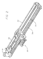
- the carriage assembly 20 (Fig. 2) is driven in reciprocation by a motor 31 ⁇ along dual support and guide rails 32, 34 ⁇ through the intermediary of a drive belt 35.
- the motor 31 is under the control of signals 31A from a digital electronic microprocessor 17 (Fig. 1A).
- the carriage assembly is represented separately at 20 when traveling to the left 16 while discharging ink 18, and at 20' when traveling to the right 17 while discharging ink 19.
- a very finely graduated encoder strip 33 is extended taut along the scanning path of the carriage assembly 20, 20', and read by an automatic optoelectronic sensor 37 to provide position and speed information 37B for the microprocessor 15.
- the codestrip 33 thus enables formation of color inkdrops at ultrahigh precision (as mentioned earlier, typically 24 pixels/mm) during scanning of the carriage assembly 20 in each direction ⁇ i. e. , either left to right (forward 20') or right to left (back 20).
- a currently preferred location for the encoder strip 33 is near the rear of the carriage tray (remote from the space into which a user's hands are inserted for servicing of the pen refill cartridges).
- Immediately behind the pens is another advantageous position for the strip 36 (Fig. 3).
- the sensor 37 is disposed with its optical beam passing through orifices or transparent portions of a scale formed in the strip.
- Print medium 4A is thereby drawn out of the print-medium roll cover 4, passed under the pens on the carriage assembly 20, 20' to receive inkdrops 18, 19 for formation of a desired image, and ejected into the print-medium bin 5.
- the carriage assembly 20, 20' includes a previously mentioned rear tray 21 (Fig. 4) carrying various electronics. It also includes bays 22 for preferably four pens 23-26 holding ink of four different colors respectively ⁇ preferably yellow in the leftmost pen 23, then cyan 24, magenta 25 and black 26.
- Each of these pens particularly in a large-format printer/plotter as shown, preferably includes a respective ink-refill valve 27.
- the pens unlike those in earlier mixed-resolution printer systems, all are relatively long and all have nozzle spacing 29 (Fig. 5) equal to one-twelfth millimeter ⁇ along each of two parallel columns of nozzles. These two columns contain respectively the odd-numbered nozzles 1 to 299, and even-numbered nozzles 2 to 300.
- the two columns thus having a total of one hundred fifty nozzles each, are offset vertically by half the nozzle spacing, so that the effective pitch of each two-column nozzle array is approximately one-twenty-fourth millimeter.
- the natural resolution of the nozzle array in each pen is thereby made approximately twenty-four nozzles (yielding twenty-four pixels) per millimeter.
- the system For resupply of ink to each pen the system includes a refill cartridge 51 (Fig. 6), with a valve 52, umbilicus 53 and connector nipple 54. The latter mates with supply tubing within the printer/plotter refill station (in the left-hand pod 3).
- Each supply tube in turn can complete the connection to the previously mentioned refill valve 27 on a corresponding one of the pens, when the carriage is halted at the refill station.
- a user manually inserts (Fig. 7) each refill cartridge 51 into the refill station as needed.
- all print modes are bidirectional. In other words, consecutive passes are printed 19, 18 while traveling in both directions, alternating left-to-right scans 17 with right-to-left 16.
- black (or other monochrome) and color are treated identically as to speed and most other parameters.
- the number of printhead nozzles used is always two hundred forty, out of the three hundred nozzles (Fig. 5) in the pens.
- the system of the preferred embodiment has three printing speed/quality settings, which determine resolution, number of passes to complete inking of each swath (or more precisely each subswath), and carriage velocities as approximately: best quality normal fast resolution (pixels/mm) 24 12 12 passes to complete swath 8 or 10 4 or 6 2 carriage velocity (cm/sec) 51 or 631 ⁇ 2 631 ⁇ 2 631 ⁇ 2.
- best quality normal fast resolution pixels/mm
- carriage velocity cm/sec
- the varying choices indicated here are for correspondingly various media ⁇ for example carriage velocity is 631 ⁇ 2 cm/sec, except that 51 cm/sec is used for best-quality printing on glossy stock.
- Resolution is the same in both horizontal and vertical directions, i. e. row and column spacings are the same so that pixels 57 (Fig. 8) are 24 mm square for all settings.
- Low-resolution printing instead calculates the inking only for every other position in the grid (along each of the perpendicular axes or dimensions) and implements that inking with one or more double-height, double-width compound inkdrop structures 58 ⁇ each made up of a two-by-two assemblage of individual inkdrops. Since calculations are done for only half the rows and half the columns, the number of points calculated is just one quarter of all the points in the grid.
- one ideal objective is row and column randomization, to minimize patterning while maintaining throughput.
- another important ideal objective is wide separation between inkdrops laid down in the same pass ⁇ and also in temporally nearby passes ⁇ to minimize puddling while maintaining throughput.
- the second rule actually arises from firing-frequency limitations, as mentioned earlier, but also of course helps to minimize overinking by spreading printed dots as much as possible. It focuses on "firing-frequency neighbors" 2.
- the maximum firing frequency is 7.5 kHz, and a design objective is to stay at least a factor of two below that value.
- the effective frequency is four to eight times lower than that value, for a very fully effective margin of error.
- the third rule is directed to overinking, and focuses on "vertical frequency" neighbors 1.
- the fourth rule is concerned with the same, but in regard to possibly-incompletely-dried inkdrops deposited in the immediately preceding pass ⁇ i. e. , what may be called a "horizontal-temporal” neighbor 6, "vertical-temporal” neighbor 8, and "diagonal-temporal” neighbor 7.
- the fifth and final rule is essentially the same as the first but focused upon the regions where adjoining masks come together.
- positions 1 and 2 are influenced primarily by pen parameters (firing capabilities), while the other positions are critical for ink and media artifacts.
- Figs. 16 through 21 display the masks chosen from those randomly generated, after testing as described above. As mentioned earlier, some of the smaller masks were generated manually but still with attention to selection of the numbers at random.
- the mask of Fig. 16 was found to produce best printed image quality for glossy stock, and also for a vinyl printing medium, and accordingly was selected for use at the "best" mode setting for those two media. It is familiarly called a “knight” printmask because the pixels assigned to each pass appear, relative to one another, two pixels over and one down ⁇ like the move of the piece called a "knight” in the game of chess.
- the Fig. 17 mask when tested produced best image quality on matte stock, and Fig. 18 best image quality when backlit ⁇ in other words, used for overhead projection or simply in a backlit display frame as in some types of advertising displays. It is a "two hundred percent of ink" mode, in which all normal inking is doubled.
- the mask of Fig. 17 is used at the "best" print-quality setting on matte, and Fig. 18 for backlit transparencies.
- the Fig. 19 mask is used in the "normal" setting for glossy, heavy matte and vinyl. Inspection of the information shows clearly that several of the location rules are relaxed.
- Fig. 20 shows a mask used for "normal” printing on backlit transparency media (at two hundred percent inking), and also for “fast” printing on glossy and vinyl stock ⁇ all at four passes and four advances.
- Fig. 21 is used for "normal” printing on matte, with four passes and two advances; and
- Fig. 22 is used at the "fast” setting on a matte medium, with two passes and one advance.
- each printhead is made with ⁇ pursuant to convention ⁇ two rows of nozzles, the two rows being offset by half the nozzle spacing in each row. If a printmode happens to call for addressing, say, all odd -numbered nozzles in one pass and all even in the next pass, this seemingly arbitrary specification has a physical significance which may be unintended: in heavily inked regions, what will fire is in the first pass the entire left-hand column of nozzles and then, in the second, the entire right-hand column.
- pens are generally made with one common ink-supply channel supplying all the ink chambers in the left-hand row, and another distinct common channel supplying all the chambers in the right-hand row. Firing all odd or all even nozzles therefore selectively drains only one or the other supply channel, tending through liquid-flow impedance effects to aggravate any tendency of some nozzles to fire weakly.
- These may be, for example, the nozzles furthest from the channel source inlets ⁇ or those which happen to have been made with aperture sizes low-within-tolerance.
- the mask of Fig. 22 calls for firing in a single pass (pass "1", for example) two vertically adjacent pixels in the upper right corner of the mask ⁇ which means two nozzles in immediate succession in the numbering sequence. These are, physically, one adjacent nozzle in each of the two columns. Thereby liquid loading is distributed equally between the two supply channels, not concentrated in one or the other. The same sharing of the hydraulic loading is seen whichever pass is considered.
- the masks are simply called up automatically. They are selected by the combination of print-quality and print-medium settings which a user of the printer/plotter enters at the control panel 12, as verified by the display 11.
- Each pass number in a particular cell of a mask is applied directly by the system central processor, to cause the carriage drive 31, medium-advance drive 42-44, encoder sensor 37, and pen nozzles (Fig. 5) with associated firing devices all to cooperate in implementing the pass-number indication. That is, they cooperate in such a way that all the pixels corresponding to-that particular cell will be printed during the indicated pass ⁇ if there is anything to print in those pixels respectively.
Abstract
- one full reciprocation (18, 19) of the heads, to discharge drops while scanning each way across the medium, with
- each step (42A) of the advance mechanism.
Description
| best quality | normal | fast | |
| resolution (pixels/mm) | 24 | 12 | 12 |
| passes to complete | 8 or 10 | 4 or 6 | 2 |
| carriage velocity (cm/sec) | 51 or 63½ | 63½ | 63½. |
- the
testing 67 is more elaborate because of the greater number of constraints from already established lines, - testing at the bottom line of the mask is particularly elaborate since it includes a test against the already-established top line, which will be vertically adjacent when the mask is stepped over the full pixel grid, and
- an
extra test 68 is included to protect the system against cycling indefinitely when earlier-established values or lines pose an intractable selection problem for later values or lines.
- no immediate neighbors in any direction ― horizontal, vertical or diagonal;
- no more than one pixel in any row, within the entire width of the printmask;
- no more than one pixel in any column, within the entire height of the printmask;
- no immediate neighbors in any direction in the immediately preceding pass; and
- adherence to the no-immediate-neighbors rule across the seams of two vertically abutted masks, or horizontally abutted masks, or both.
Claims (8)
- Apparatus for printing a color image on a printing medium (4A); said apparatus comprising:bidirectional scanning printhead means (20, 20', 31, 35) for scanning bidirectionally across such printing medium, to discharge color-ink droplets (18, 19) at ultrahigh resolution while scanning in each direction (16, 17), and thereby form swaths (Fig. 12) of such color image on such printing medium in rows and columns (Fig. 15), said rows being spaced apart by a pixel-row spacing (28);said printhead means including plural inkjet printheads (20, 20', 23-26) to print plural colors respectively, which plural printheads are mutually at least partially aligned with respect to the longitudinal direction of the printing medium; whereby the plural printheads print respective color swaths (Fig. 12) which at least partially overlap (79) in that longitudinal direction, and wherein each printhead has nozzles (#1-#300) spaced apart at the same spacing (28) as the pixel rows;printing-medium advance means (42) for intermittent operation (42A) to move such printing medium longitudinally to enable displacement, when desired, of successive swaths (Fig. 12) along such medium; andcontrol means (15) for alternating (A) one full reciprocation (16-17) of the scanning printhead means, to discharge color-ink droplets (18, 19) while scanning in each direction (16,, 17) across such printing medium and back, with (B) each operation (42A) of the printing-medium advance means (42).
- The apparatus of claim 1, wherein:the control means comprise means (20B) for operating the printhead means (20, 20') to print, while scanning in each direction (16, 17), a respective generally fixed nonzero fraction of the amount of each secondary color (23 plus 24, or 23 plus 25, or 24 plus 25) to be printed in a corresponding part of such image; andthe overall color appearance for each secondary color is substantially a consistent color appearance partway between two color appearances respectively produced by scanning in two directions; andpreferably the respective generally fixed nonzero fractions for all the swaths are generally equal, and said consistent color appearance for each secondary color is substantially an average of two color appearances respectively produced by scanning in two directions.
- The apparatus of claim 1, wherein:the control means (15) impose a constraint, as stated below, in terms of a triad of control colors, said triad being either:three color secondaries (23 plus 24, or 23 plus 25, or 24 plus 25), orthree color primaries (23, 24, 25);the control means comprise means for operating the printhead means to print:while scanning in a first direction (16) generally all spots of two colors (for primaries 23, 24 or 23, 25 or 24, 25) of said triad to be printed in each swath ( ), andwhile scanning in a second, opposite direction (17), generally all spots of a third color (for primaries 25, 24 or 23 respectively) of said triad, and of black (26), to be printed in each swath ( ); andeach color of the triad is generally always deposited during scanning in a respective fixed, consistent direction (e. g., 16 for 23); andthe overall color appearance for each color of the triad is substantially consistent.
- The apparatus of claim 1, wherein:the control means comprise means for operating the printhead means to complete each swath in eight passes, with printing in each pass, and with four printing-medium advances; andpreferably the operating means provide best quality of printing on vinyl, in which case preferably the operating means impose an eight-by-eight "knight"-pattern (Fig. 16) printmask.
- The apparatus of claim 1, wherein:the control means comprise means for operating the printhead means to complete each swath in four passes, with printing in each pass, and with two printing-medium advances; andpreferably the operating means provide normal quality of printing on matte stock, in which case preferably the operating means impose a four-by-four printmask (Fig. 21) with the pattern:
2 1 4 3 4 3 2 1 1 2 3 4 3 4 1 2. - The apparatus of claim 1, wherein:the control means comprise means for operating the printhead means to complete each swath in two passes, with printing in each pass, and with one printing-medium advance; andpreferably the operating means provide fast printing on matte stock, in which case preferably the operating means impose a four-by-four printmask (Fig. 22) with the pattern:
1 2 1 2 1 2 1 2 2 1 2 1 2 1 2 1. - A method for printing a color image on a printing medium (4A), using bidirectional scanning printhead means (20, 20') comprising plural printheads (23-26) each with nozzles (#1-#300) spaced apart at a nozzle spacing (28), printing-medium advance means (31, 35), and control means (15); said method comprising the steps of:scanning the printhead means bidirectionally (16, 17) across the printing medium, to discharge (18, 19) color-ink droplets at ultrahigh resolution while scanning in each direction, and thereby form swaths (Fig. 12) of the color image on the printing medium in a pixel grid of rows and columns (Fig. 15), said rows being spaced apart by a pixel-row spacing equal to said nozzle spacing (28);wherein said scanning step includes printing plural bands of plural colors respectively, which plural bands are mutually at least partially overlapping (Fig. 12) with respect to the longitudinal direction (85) of the printing medium; andintermittent operation (42A) of the printing-medium advance means to semistagger the swaths.
- The method of claim 7, wherein:the scanning step comprises operating (20B) the printhead means (20, 20') to print, while scanning in each direction (16, 17), a respective generally fixed nonzero fraction of each secondary color (23 plus 24, or 23 plus 25, or 24 plus 25) to be printed in a corresponding part of such image; andthe overall color appearance for each pair of generally adjacent spots of each secondary color is substantially a consistent color appearance partway between two color appearances respectively produced by scanning in two directions.
Applications Claiming Priority (2)
| Application Number | Priority Date | Filing Date | Title |
|---|---|---|---|
| US08/810,747 US6250739B1 (en) | 1997-03-04 | 1997-03-04 | Bidirectional color printmodes with semistaggered swaths to minimize hue shift and other artifacts |
| US810747 | 2004-03-25 |
Publications (3)
| Publication Number | Publication Date |
|---|---|
| EP0863479A2 true EP0863479A2 (en) | 1998-09-09 |
| EP0863479A3 EP0863479A3 (en) | 2000-08-16 |
| EP0863479B1 EP0863479B1 (en) | 2006-05-24 |
Family
ID=25204606
Family Applications (1)
| Application Number | Title | Priority Date | Filing Date |
|---|---|---|---|
| EP98301561A Expired - Lifetime EP0863479B1 (en) | 1997-03-04 | 1998-03-03 | Method and apparatus for multipass colour ink jet printing |
Country Status (5)
| Country | Link |
|---|---|
| US (1) | US6250739B1 (en) |
| EP (1) | EP0863479B1 (en) |
| JP (1) | JPH10244693A (en) |
| DE (1) | DE69834592T2 (en) |
| ES (1) | ES2264185T3 (en) |
Cited By (9)
| Publication number | Priority date | Publication date | Assignee | Title |
|---|---|---|---|---|
| EP1029693A1 (en) * | 1999-02-17 | 2000-08-23 | Hewlett-Packard Company | Printing with multiple passes |
| EP1072421A2 (en) | 1999-07-29 | 2001-01-31 | Hewlett-Packard Company | Apparatus and method for hue shift compensation in a bidirectional printer |
| EP1085457A1 (en) * | 1999-09-20 | 2001-03-21 | Hewlett-Packard Company | Banding reduction in multipass printmodes |
| EP1088669A2 (en) * | 1999-09-30 | 2001-04-04 | Canon Kabushiki Kaisha | Printing apparatus and printing method |
| EP1093923A1 (en) * | 1999-10-20 | 2001-04-25 | Canon Kabushiki Kaisha | High resolution printing |
| EP1217578A3 (en) * | 2000-12-18 | 2003-07-16 | Xerox Corporation | Image processing method and apparatus |
| US6899413B2 (en) | 2000-01-25 | 2005-05-31 | Canon Kabushiki Kaisha | Bidirectional printing method and apparatus with reduced color unevenness |
| EP1582358A1 (en) * | 2004-03-30 | 2005-10-05 | Hewlett-Packard Development Company, L.P. | Formation of images |
| WO2017064610A1 (en) * | 2015-10-14 | 2017-04-20 | Funai Electric Co., Ltd. | Imaging apparatus and method for reducing banding |
Families Citing this family (13)
| Publication number | Priority date | Publication date | Assignee | Title |
|---|---|---|---|---|
| JP4277164B2 (en) * | 2000-07-24 | 2009-06-10 | セイコーエプソン株式会社 | Recording method and recording apparatus |
| US6543871B1 (en) * | 2000-11-21 | 2003-04-08 | Electronics For Imaging, Inc. | Mask generator and image mask patterns |
| US7207652B2 (en) * | 2003-10-17 | 2007-04-24 | Lexmark International, Inc. | Balanced satellite distributions |
| US6866365B1 (en) | 2004-04-01 | 2005-03-15 | Eastman Kodak Company | Bi-directional color printer and method of printing |
| US20060087527A1 (en) * | 2004-10-27 | 2006-04-27 | De Pena Alejandro M | Method for preparing a print mask |
| US7452046B2 (en) * | 2004-10-27 | 2008-11-18 | Hewlett-Packard Development Company, L.P. | Method for preparing a print mask |
| US7517039B2 (en) * | 2005-09-19 | 2009-04-14 | Marvell International Technology Ltd. | Enabling increased print speed by eliminating nozzle firing sequencing |
| US20090027696A1 (en) * | 2007-07-24 | 2009-01-29 | Quintana Jason M | Printmode architecture |
| US8452725B2 (en) * | 2008-09-03 | 2013-05-28 | Hamid Hatami-Hanza | System and method of ontological subject mapping for knowledge processing applications |
| US8336982B2 (en) | 2010-07-14 | 2012-12-25 | Hewlett-Packard Development Company, L.P. | Fluid ejection printing with automatic print mode switching |
| US8939546B2 (en) | 2012-07-12 | 2015-01-27 | Hewlett-Packard Industrial Printing Ltd. | Coordinated printhead operation |
| WO2018140027A1 (en) | 2017-01-27 | 2018-08-02 | Hewlett-Packard Development Company, L.P. | Print head nozzle spitting |
| JP7089664B2 (en) | 2018-03-23 | 2022-06-23 | セイコーエプソン株式会社 | Recording device |
Citations (5)
| Publication number | Priority date | Publication date | Assignee | Title |
|---|---|---|---|---|
| US4748453A (en) | 1987-07-21 | 1988-05-31 | Xerox Corporation | Spot deposition for liquid ink printing |
| US4963882A (en) | 1988-12-27 | 1990-10-16 | Hewlett-Packard Company | Printing of pixel locations by an ink jet printer using multiple nozzles for each pixel or pixel row |
| US4965593A (en) | 1989-07-27 | 1990-10-23 | Hewlett-Packard Company | Print quality of dot printers |
| US5555006A (en) | 1993-04-30 | 1996-09-10 | Hewlett-Packard Company | Inkjet printing: mask-rotation-only at page extremes; multipass modes for quality and throughput on plastic media |
| US5561449A (en) | 1993-04-30 | 1996-10-01 | Hewlett-Packard Company | Position leading, delay and timing uncertainty to improve position & quality in bidirectional printing |
Family Cites Families (17)
| Publication number | Priority date | Publication date | Assignee | Title |
|---|---|---|---|---|
| US4540996A (en) * | 1982-05-11 | 1985-09-10 | Canon Kabushiki Kaisha | Recording apparatus |
| JPS59114066A (en) * | 1982-12-20 | 1984-06-30 | Citizen Watch Co Ltd | Dot line printer |
| JPS60199662A (en) * | 1984-03-23 | 1985-10-09 | Oki Electric Ind Co Ltd | Color ink jet recorder |
| EP0162963B1 (en) * | 1984-04-27 | 1989-03-08 | Siemens Aktiengesellschaft | Ink-writing apparatus reproducing multicolour characters and/or patterns |
| DE3620334A1 (en) * | 1985-06-21 | 1987-01-02 | Sharp Kk | PRINTING PROCESS |
| US5044796A (en) * | 1989-01-19 | 1991-09-03 | Hewlett-Packard Company | Bidirectional printing method in accordance with vertical breaks |
| US4967203A (en) * | 1989-09-29 | 1990-10-30 | Hewlett-Packard Company | Interlace printing process |
| US5583550A (en) * | 1989-09-29 | 1996-12-10 | Hewlett-Packard Company | Ink drop placement for improved imaging |
| JP2986124B2 (en) * | 1991-06-14 | 1999-12-06 | キヤノン株式会社 | Ink jet recording device |
| EP0564252B1 (en) * | 1992-03-31 | 2003-09-10 | Canon Kabushiki Kaisha | Ink jet recording method and apparatus |
| US5512923A (en) * | 1992-09-30 | 1996-04-30 | Hewlett-Packard Company | Color variation control method for ink-jet printers |
| JP3161094B2 (en) * | 1992-10-08 | 2001-04-25 | 富士ゼロックス株式会社 | Recording method in ink jet recording apparatus |
| US5455610A (en) * | 1993-05-19 | 1995-10-03 | Xerox Corporation | Color architecture for an ink jet printer with overlapping arrays of ejectors |
| EP1162567B1 (en) * | 1993-05-27 | 2008-08-06 | Canon Kabushiki Kaisha | Ink jet recording method and apparatus |
| US5818474A (en) * | 1993-06-30 | 1998-10-06 | Canon Kabushiki Kaisha | Ink-jet recording apparatus and method using asynchronous masks |
| JPH07214797A (en) * | 1994-01-03 | 1995-08-15 | Xerox Corp | Color printer |
| JP3606403B2 (en) * | 1995-04-27 | 2005-01-05 | セイコーエプソン株式会社 | Printing apparatus and printing method |
-
1997
- 1997-03-04 US US08/810,747 patent/US6250739B1/en not_active Expired - Lifetime
-
1998
- 1998-02-25 JP JP10059084A patent/JPH10244693A/en active Pending
- 1998-03-03 EP EP98301561A patent/EP0863479B1/en not_active Expired - Lifetime
- 1998-03-03 ES ES98301561T patent/ES2264185T3/en not_active Expired - Lifetime
- 1998-03-03 DE DE69834592T patent/DE69834592T2/en not_active Expired - Lifetime
Patent Citations (6)
| Publication number | Priority date | Publication date | Assignee | Title |
|---|---|---|---|---|
| US4748453A (en) | 1987-07-21 | 1988-05-31 | Xerox Corporation | Spot deposition for liquid ink printing |
| US4963882A (en) | 1988-12-27 | 1990-10-16 | Hewlett-Packard Company | Printing of pixel locations by an ink jet printer using multiple nozzles for each pixel or pixel row |
| US4963882B1 (en) | 1988-12-27 | 1996-10-29 | Hewlett Packard Co | Printing of pixel locations by an ink jet printer using multiple nozzles for each pixel or pixel row |
| US4965593A (en) | 1989-07-27 | 1990-10-23 | Hewlett-Packard Company | Print quality of dot printers |
| US5555006A (en) | 1993-04-30 | 1996-09-10 | Hewlett-Packard Company | Inkjet printing: mask-rotation-only at page extremes; multipass modes for quality and throughput on plastic media |
| US5561449A (en) | 1993-04-30 | 1996-10-01 | Hewlett-Packard Company | Position leading, delay and timing uncertainty to improve position & quality in bidirectional printing |
Cited By (16)
| Publication number | Priority date | Publication date | Assignee | Title |
|---|---|---|---|---|
| EP1029693A1 (en) * | 1999-02-17 | 2000-08-23 | Hewlett-Packard Company | Printing with multiple passes |
| EP1072421A2 (en) | 1999-07-29 | 2001-01-31 | Hewlett-Packard Company | Apparatus and method for hue shift compensation in a bidirectional printer |
| EP1085457A1 (en) * | 1999-09-20 | 2001-03-21 | Hewlett-Packard Company | Banding reduction in multipass printmodes |
| US6896356B1 (en) | 1999-09-30 | 2005-05-24 | Canon Kabushiki Kaisha | Print apparatus and printing method for forming a color image by applying different color inks to a printing material using a recording head |
| EP1088669A2 (en) * | 1999-09-30 | 2001-04-04 | Canon Kabushiki Kaisha | Printing apparatus and printing method |
| EP1088669A3 (en) * | 1999-09-30 | 2002-08-21 | Canon Kabushiki Kaisha | Printing apparatus and printing method |
| EP1093923A1 (en) * | 1999-10-20 | 2001-04-25 | Canon Kabushiki Kaisha | High resolution printing |
| US6604806B1 (en) | 1999-10-20 | 2003-08-12 | Canon Kabushiki Kaisha | High resolution printing |
| US6899413B2 (en) | 2000-01-25 | 2005-05-31 | Canon Kabushiki Kaisha | Bidirectional printing method and apparatus with reduced color unevenness |
| US7011391B2 (en) | 2000-01-25 | 2006-03-14 | Canon Kabushiki Kaisha | Bidirectional printing method and apparatus with reduced color unevenness |
| US7131713B2 (en) | 2000-01-25 | 2006-11-07 | Canon Kabushiki Kaisha | Bidirectional printing method and apparatus with reduced color unevenness |
| US7455379B2 (en) | 2000-01-25 | 2008-11-25 | Canon Kabushiki Kaisha | Bidirectional printing method and apparatus with reduced color unevenness |
| EP1217578A3 (en) * | 2000-12-18 | 2003-07-16 | Xerox Corporation | Image processing method and apparatus |
| EP1582358A1 (en) * | 2004-03-30 | 2005-10-05 | Hewlett-Packard Development Company, L.P. | Formation of images |
| US7168784B2 (en) | 2004-03-30 | 2007-01-30 | Hewlett-Packard Development Company, L.P. | Formation of images |
| WO2017064610A1 (en) * | 2015-10-14 | 2017-04-20 | Funai Electric Co., Ltd. | Imaging apparatus and method for reducing banding |
Also Published As
| Publication number | Publication date |
|---|---|
| EP0863479B1 (en) | 2006-05-24 |
| DE69834592D1 (en) | 2006-06-29 |
| ES2264185T3 (en) | 2006-12-16 |
| EP0863479A3 (en) | 2000-08-16 |
| DE69834592T2 (en) | 2006-11-09 |
| US6250739B1 (en) | 2001-06-26 |
| JPH10244693A (en) | 1998-09-14 |
Similar Documents
| Publication | Publication Date | Title |
|---|---|---|
| US6367908B1 (en) | High-resolution inkjet printing using color drop placement on every pixel row during a single pass | |
| US6019454A (en) | Multipass inkjet printmodes with randomized dot placement, to minimize patterning and liquid loading | |
| EP0863480B1 (en) | Method and apparatus for multipass colour ink jet printing | |
| US6250739B1 (en) | Bidirectional color printmodes with semistaggered swaths to minimize hue shift and other artifacts | |
| US5600353A (en) | Method of transitioning between ink jet printing modes | |
| US5949453A (en) | Mixed resolution printing for color and monochrome printers | |
| EP0730968B1 (en) | Resolution-dependent and color-dependent print masking | |
| EP0622212A2 (en) | Images printing method | |
| US6142605A (en) | Bidirectional color printing using multipass printmodes with at least partially swath-aligned inkjet printheads | |
| EP0824073A2 (en) | Inkjet printing: mask-rotation-only at page extremes: multipass modes for quality and throughput on plastic media | |
| EP0864429B1 (en) | Random printmasks in a multilevel inkjet printer | |
| US6086181A (en) | Maximum-diagonal print mask and multipass printing modes, for high quality and high throughput with liquid-base inks | |
| US6582056B2 (en) | Edge enhancement depletion technique for over-sized ink drops to achieve high resolution X/Y axes addressability in injet printing | |
| US6017113A (en) | Mixed-density print masking in a mixed-swath-height printer | |
| US6217150B1 (en) | Method of printing with an ink jet printer using multiple carriage speeds | |
| US6565191B1 (en) | Method of color shingling to reduce visible printing defects | |
| KR19980032994A (en) | How to control distribution of color printing system and color drop | |
| US5959646A (en) | Method of printing with an ink jet printer using independent shingling on a raster by raster basis | |
| US5779377A (en) | Printing apparatus | |
| EP0730367A1 (en) | Method and system for interlaced printing | |
| JPH10157171A (en) | Region filling depletion method independently of plot for high-resolution x/y axis address assigning performance in ink-jet print | |
| US6629752B1 (en) | Method of ink jet printing with enhanced shingling and printer apparatuses for the same | |
| EP1216154B1 (en) | Method of ink jet printing with enhanced shingling and printer apparatuses for the same | |
| EP0837424A2 (en) | Printing system | |
| KR19980032992A (en) | Ossu printing system and multi-color inkjet printing method |
Legal Events
| Date | Code | Title | Description |
|---|---|---|---|
| PUAI | Public reference made under article 153(3) epc to a published international application that has entered the european phase |
Free format text: ORIGINAL CODE: 0009012 |
|
| AK | Designated contracting states |
Kind code of ref document: A2 Designated state(s): DE ES FR GB |
|
| AX | Request for extension of the european patent |
Free format text: AL;LT;LV;MK;RO;SI |
|
| PUAL | Search report despatched |
Free format text: ORIGINAL CODE: 0009013 |
|
| AK | Designated contracting states |
Kind code of ref document: A3 Designated state(s): AT BE CH DE DK ES FI FR GB GR IE IT LI LU MC NL PT |
|
| AX | Request for extension of the european patent |
Free format text: AL;LT;LV;MK;RO;SI |
|
| 17P | Request for examination filed |
Effective date: 20010118 |
|
| RAP1 | Party data changed (applicant data changed or rights of an application transferred) |
Owner name: HEWLETT-PACKARD COMPANY, A DELAWARE CORPORATION |
|
| AKX | Designation fees paid |
Free format text: DE ES FR GB |
|
| 17Q | First examination report despatched |
Effective date: 20030716 |
|
| GRAP | Despatch of communication of intention to grant a patent |
Free format text: ORIGINAL CODE: EPIDOSNIGR1 |
|
| GRAS | Grant fee paid |
Free format text: ORIGINAL CODE: EPIDOSNIGR3 |
|
| GRAA | (expected) grant |
Free format text: ORIGINAL CODE: 0009210 |
|
| AK | Designated contracting states |
Kind code of ref document: B1 Designated state(s): DE ES FR GB |
|
| REG | Reference to a national code |
Ref country code: GB Ref legal event code: FG4D |
|
| REF | Corresponds to: |
Ref document number: 69834592 Country of ref document: DE Date of ref document: 20060629 Kind code of ref document: P |
|
| REG | Reference to a national code |
Ref country code: ES Ref legal event code: FG2A Ref document number: 2264185 Country of ref document: ES Kind code of ref document: T3 |
|
| ET | Fr: translation filed | ||
| PLBE | No opposition filed within time limit |
Free format text: ORIGINAL CODE: 0009261 |
|
| STAA | Information on the status of an ep patent application or granted ep patent |
Free format text: STATUS: NO OPPOSITION FILED WITHIN TIME LIMIT |
|
| 26N | No opposition filed |
Effective date: 20070227 |
|
| REG | Reference to a national code |
Ref country code: GB Ref legal event code: 732E Free format text: REGISTERED BETWEEN 20120329 AND 20120404 |
|
| REG | Reference to a national code |
Ref country code: ES Ref legal event code: PC2A Owner name: HEWLETT-PACKARD DEVELOPMENT COMPANY, L.P. Effective date: 20120911 |
|
| PGFP | Annual fee paid to national office [announced via postgrant information from national office to epo] |
Ref country code: DE Payment date: 20130221 Year of fee payment: 16 Ref country code: ES Payment date: 20130305 Year of fee payment: 16 Ref country code: GB Payment date: 20130228 Year of fee payment: 16 |
|
| PGFP | Annual fee paid to national office [announced via postgrant information from national office to epo] |
Ref country code: FR Payment date: 20130429 Year of fee payment: 16 |
|
| REG | Reference to a national code |
Ref country code: DE Ref legal event code: R119 Ref document number: 69834592 Country of ref document: DE |
|
| GBPC | Gb: european patent ceased through non-payment of renewal fee |
Effective date: 20140303 |
|
| REG | Reference to a national code |
Ref country code: FR Ref legal event code: ST Effective date: 20141128 |
|
| REG | Reference to a national code |
Ref country code: DE Ref legal event code: R119 Ref document number: 69834592 Country of ref document: DE Effective date: 20141001 |
|
| PG25 | Lapsed in a contracting state [announced via postgrant information from national office to epo] |
Ref country code: GB Free format text: LAPSE BECAUSE OF NON-PAYMENT OF DUE FEES Effective date: 20140303 Ref country code: DE Free format text: LAPSE BECAUSE OF NON-PAYMENT OF DUE FEES Effective date: 20141001 Ref country code: FR Free format text: LAPSE BECAUSE OF NON-PAYMENT OF DUE FEES Effective date: 20140331 |
|
| REG | Reference to a national code |
Ref country code: ES Ref legal event code: FD2A Effective date: 20150428 |
|
| PG25 | Lapsed in a contracting state [announced via postgrant information from national office to epo] |
Ref country code: ES Free format text: LAPSE BECAUSE OF NON-PAYMENT OF DUE FEES Effective date: 20140304 |