This invention relates to audio data transmission and
recording.
Recently, digital audio apparatuses such as a compact
disc (CD) player and a so-called mini disc (MD) using a
small-size optical disc are widely spread, enabling to
easily reproduce an audio signal of a high quality.
On the other hand, however, a plenty of music software
available may be copied without a particular limit and
various copy prevention methods have been suggested.
Especially in the case of the aforementioned digital
audio, the audio signal is not deteriorated through
copying, which makes the copy prevention very important.
In the case of the aforementioned digital audio, a copy
inhibit control
signal consisting of a copy inhibit symbol or a copy generation
limit symbol as well as an author right data are additionally
recorded in additional to a digital audio signal on a recording
medium, so as to prevent copying or to trace a recording medium
copied using an authorized data.
However, when a digital audio signal is converted into an
analog audio signal, the aforementioned additional digital data
is not contained in the analog audio signal, disabling to
control copy prevention or trace an unauthorized copying.
To cope with this, it is desired to overlap the
aforementioned additional information in an analog audio
signal. However, it has been quite difficult to overlap an
additional information on an analog audio signal without
deteriorating the audio signal S/N ratio, although such a
technique of overlapping an additional information is expected
to enable a novel service in the information-oriented society.
To cope with this, a spectrum diffusion method is
considered for overlapping an additional information. This
method is preferable for overlapping a plenty of data, but when
used for an audio signal, it is impossible to obtain a
sufficient band width and it has been difficult to realize in
the field of music source and the like which requires to
maintain a high S/N ration.
Moreover, in order to carry out a spectrum diffusion on
an audio signal, there arises a problem of synchronization.
Firstly, in an audio signal, it is necessary to provide a
significantly long periodicity so as to obtain a sufficient S/N
ratio, and a quite a long time is required if an ordinary
serial search is used for synchronization establishment.
In contrast to this, a method called matched filter is
known for improving the synchronization establishment in a
dedicated circuit. However, when the periodicity is so
long, the circuit size becomes great and it is not
practical in costs to mount such a circuit in a
reproduction apparatus and a reception apparatus. In a
case when a decoder is mounted on an audio reproduction
apparatus for carrying out a copy management from an analog
audio input, a method desired is one which is easily
available at a low price and can be used in common for
various apparatuses. Because of these problems, it has
been considered difficult to realize a data multiplexing
using the spectrum diffusion method.
Respective different aspects of the present invention
are set forth in the respective independent claims hereof.
An audio data transmission apparatus according to
another aspect of the present invention includes gap insert
position detecting means and gap insert means, so that a
gap is inserted by the gap inserting means at a position
detected by the gap insert position detecting means. This
gap is used as a control signal for multiplexing on the
audio signal a spectrum-diffused data obtained according to
an additional information.
Moreover, an audio data recording apparatus according
to a further aspect of the present invention uses as a
control signal the gap from the gap detection means, so
that demodulation means demodulates a spectrum-diffused
data multiplexed on an audio signal, and according to the
demodulated additional information, correction means
correct the spectrum-diffused data.
Moreover, an audio data recording medium according to
yet another aspect of the present invention contains an
additional information as a spectrum-diffused data which is
multiplexed on an audio signal using a gap as a control
signal.
A preferred form of implementation of the present
invention described below provides an audio data
transmission apparatus and method, an audio data recording
apparatus, and an audio data recording medium which are
capable of multiplexing spectrum-diffused data on an analog
audio signal with the least deterioration of the audio
quality.
The preferred form of implementation of the present
invention provides an audio data transmission apparatus and
method for transmitting, over audio data, additional
information such as a copy inhibit control signal and
author right information for tracing an unauthorized copy;
an audio data recording apparatus for recording the audio
data which has been received; and an audio data recording
medium containing the additional information overwritten on
the audio data.
The invention will now be further described, by way of
illustrative and non-limiting example, with reference to
the accompanying drawings, in which:
Fig. 1 is a block diagram showing an audio data
transmission apparatus and method according to an
embodiment of the present invention.
Fig. 2 is a timing chart for explanation of an example
of controlling a spectrum diffusion signal by way of a gap
width modulation using the aforementioned embodiment shown
in Fig. 1.
Fig. 3 is a timing chart for explanation of a time
division transmission of a spectrum diffusion signal using
the aforementioned embodiment of Fig. 1.
Fig. 4 is a block diagram showing an audio data
reproduction apparatus according to an embodiment of the
present invention.
Fig. 5 is a timing chart for explanation of a demodulation
procedure of a spectrum diffusion signal using the
aforementioned embodiment of Fig. 4.
Fig. 6 is a block diagram showing an audio data
transmission apparatus and method according to another
embodiment of the present invention.
Fig. 7 is a flowchart for explanation of the operation of
the embodiment of Fig. 6.
Fig. 8 is a timing chart for explanation of control of a
spectrum diffusion signal by way of a gap signal of the
embodiment shown in Fig. 6.
Fig. 9 is a timing chart for explanation of a specific
example in which a spectrum diffusion signal is selectively
inserted in a portion of an audio signal having a large
amplitude and a wide band width where the masking effect can
be expected in the embodiment of Fig. 6.
Fig. 10 is a timing chart for explanation of a specific
example of other operation in the embodiment of Fig. 6.
Fig. 11 shows a waveform for explanation of frequency band
limit in a spectrum diffusion signal so as to cope with
transmission deterioration due to the audio compression
technique.
Fig. 12 shows a specific example of a data insertion
according to the embodiment of Fig. 6.
Fig. 13 shows another specific example of data insertion
according to the embodiment of Fig. 6.
Fig. 14 is a block diagram showing an audio data
reproduction apparatus according to still another embodiment
of the present invention.
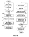
Fig. 15 is a timing chart explaining the operation of the
embodiment of the aforementioned Fig. 14.
Fig. 16 is a block diagram showing an audio data recording
apparatus according to yet another embodiment of the present
invention.
Description will now be directed to the audio data
transmission apparatus and apparatus, the audio data recording
apparatus, and audio data recording medium according to
embodiments of the present invention with reference to the
attached drawings.
Firstly, explanation will be given on the audio data
transmission apparatus and method according to the embodiment.
This transmission apparatus is for multiplexing on an analog
audio signal an additional information such as a copy
prevention control signal or author right information which has
been made into a spectrum-diffused data, and includes an
encoder 1 shown in Fig. 1.
This encoder 1 includes: a modulator 3 for carrying out
a spectrum diffusion on a data input Di which is the
aforementioned additional information supplied through a data
input terminal 2; a gap insert position detection block 7 for
detecting a position allowing a gap insertion in an audio
signal input Si supplied from a signal input terminal 6; a gap
inserter 8 for inserting the gap at the insertion position
detected by this gap insert position detection block 7; and a
modulation signal adder 9 for multiplexing the
spectrum-diffused data on the audio signal Si using as a
control signal the gap which has been inserted by the gap
inserter 8.
In this encoder 1, the input data Di is subjected to
spectrum diffusion in the modulator 3 and continuously written
into a first-in first-out (FIFO) 5 by a write control signal
(WE) supplied from a memory control block 4.
A gap is inserted from the gap inserter 8 at a gap insert
start position detected by the gap insert position detection
block 7 in the audio signal Si supplied from the input terminal
6. An embedded data Dem divided from the FIFO 5 by a read-out
control signal (RE) from the memory control block 4 is added
by the modulation signal adder 9 after the aforementioned gap
on the audio signal for output as an audio signal output So
from an output terminal 10.
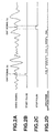
A specific example of multiplexing a spectrum diffusion
signal on the audio signal using this encoder 1 will be
explained with reference to Fig. 2. The width of a gap signal
G1 and the width of a gap signal G2 are varied so as to be
respectively defined as a start pulse in Fig. 2B and a stop
pulse in Fig. 2C, so that a spectrum diffusion signal is
multiplexed between the gap signal G1 and the gap signal G2 on
the audio signal shown in Fig. 2A.
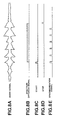
Fig. 3 explains another specific example of using this
encoder 1 for dividing and multiplexing the spectrum diffusion
signal on the audio signal. The spectrum diffusion signal
shown in Fig. 3A is time-divided at a predetermined length as
shown in Fig. 3B, so that each division is multiplexed on the
audio signal after a start pulse of Fig. 3C. Thus, it is
possible to multiplex the spectrum diffusion signal only at a
high level position of the audio signal having a high masking
effect, improving the S/N for the hearing sense.
It should be noted that it is also possible to multiplex
the aforementioned spectrum diffusion signal at a position of
a wider frequency spectrum, which also improves the S/N on the
hearing sense.
The spectrum diffusion signal which has been time-divided
and transmitted by the encoder 1 is demodulated according to
the aforementioned gap by a decoder shown in Fig. 4.
The decoder 11 is supplied with an audio signal input So
(multiplexed with the spectrum diffusion signal) through a
signal input terminal 12, from which the gap serving as the
aforementioned start pulse is detected by a gap detector 13 and
is supplied to a memory control block 14. The memory control
block 14 supplies a write control signal (WE) to a FIFO 16 so
that a modulation signal which has been isolated from the audio
signal by a modulation signal isolator 15 is intermittently
written into the FIFO 16. Moreover, the memory control block
14 supplies a read-out control signal to the FIFO 16 so that
the aforementioned modulation signal is returned to a
continuous spectrum diffusion signal as shown in Fig. 5B which
is supplied to a demodulator 17. The demodulator 17 carries
out a reverse spectrum diffusion onto the aforementioned
continuous modulation signal, so as to be made back to the
previous additional information data Do.
Here, the memory may be other than the FIFO memory if it
is possible to control to carry out the same thing.
Moreover, under a particular condition, it is possible to
control a modulation shift register in the spectrum diffusion
(or reverse diffusion) apparatus, so as to replace the
function of this memory. In such a case, the clock of the
shift register is controlled by the gap. Thus, there is a
possibility to reduce the size of the entire apparatus.
Description will now be directed to an encoder and a
decoder including a modulator and a demodulator having the
function of the aforementioned memory or the shift register.
Fig. 6 shows an encoder 20 including a modulator 29 having
a memory function or a shift register function.
An audio signal Si supplied through a signal input
terminal 21 is firstly supplied to an envelope detection block
23 constituting a gap insert position detection block 22. This
envelope detection block 23 detects an attack portion equal to
or above a predetermined level in the audio signal input Si.
Moreover, the aforementioned audio signal input Si is also
supplied to a spectrum analysis block 24 constituting the
aforementioned gap insert position detection block 22, so as
to detect a discontinuous portion of a spectrum immediately
before the aforementioned attack portion.
Furthermore, the envelope detection block 24 detects a
portion having a sufficiently small amplitude.
The aforementioned audio signal input Si is also supplied
to a delay circuit 26. The input audio signal delayed by this
delay circuit 26 is supplied to a gap inserter 27. This gap
inserter 27 is controlled by a controller 25.
The controller 25 determines a position enabling insert
of the aforementioned gap according to the detection outputs
from the envelope detection block 23 and the spectrum analysis
block 24 of the aforementioned gap insert detection block 22,
and makes to insert the aforementioned gap at the position
determined from the gap inserter 27. This gap is used as a
control signal for a spectrum diffusion signal which will be
recorded after this.
The data input Di to be embedded in the aforementioned
audio signal is supplied through a data input terminal 28 to
a modulator 29. The modulator 29 carried out a spectrum
diffusion onto the aforementioned data input Di, which is
temporarily recorded in the modulator 29 together with the
synchronization, start, stop control timings. In
synchronization with the gap insert, a predetermined width or
a division is outputted from the modulator 29 and added by a
mixer 30 to the audio signal, which is outputted as an audio
signal output So from an output terminal 31.
Fig. 7 is a flowchart showing the operation of this
encoder. That is, in steps S1 to S3. a gap insert position is
detected by the gap insert position detection block 22, and
instep S4, the modulator 29 is used to write into a waveform
of a spectrum diffused data according to the data input Di.
If in step S2 a frequency spectrum immediately before the
attack is not found to be discontinuous and if in step S3 the
amplitude is not found sufficiently small, control is passed
to step S5 where a waveform dedicated for synchronization is
written.
When multiplexing a spectrum diffusion signal on an audio
signal, conventionally, the signal has been recorded
continuously because of its feature. Although the sound
quality deterioration is reduced by the hearing sense masking
if the audio signal is sufficiently great with respect to the
spectrum diffusion signal, the deterioration cannot be ignored
for the area where the audio signal is very small.
In this encoder 20, it is possible to selectively
multiplex a spectrum diffusion signal at arbitrary positions
and to restore them as a continuous signal.
Consequently, in music for example, by recording the
spectrum diffusion signal only at portions where the sound
level is sufficiently great, it is possible to maintain a
sufficient S/N on the hearing sense satisfying a high quality
required.
Operation examples of this encoder 20 will be detailed
below with reference to Fig. 8 to Fig. 10.
In Fig. 8, the gap signal has several values according to
the width, level, and waveform, so as to realize functions of
a start, stop, synchronization signal, and synchronization
protection. At an arbitrary position of the audio signal shown
in Fig. 8A, a start signal is inserted as shown in Fig. 8C,
from which the spectrum diffusion recording is started as shown
in Fig. 8B, and the recording is terminated by a stop signal
at the timing shown in Fig. 8D. Moreover, if necessary, a
synchronous signal or a signal of synchronization protection
is inserted as shown in Fig. 8E. Thus, it is possible to
insert a spectrum diffusion signal at a desired interval. In
this specific example, it is possible to instantaneously
determine the spectrum diffusion start position and end
position and the synchronization position, which enables to
realize a rapid detection.
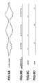
Fig. 9 shows a specific example of selectively inserting
a spectrum diffusion signal at such a portion of a great
amplitude and band width where the masking effect can be
expected according to the audio signal amplitude. That is, a
start pulse shown in Fig. 9C and a stop pulse shown in Fig. 9D
are used to divide a spectrum diffusion signal as shown in Fig.
9B, so as to be multiplexed in the portions having a great
amplitude in the audio signal shown in Fig. 9A. The S/N for
the hearing sense is improved by not inserting the spectrum
diffusion signal in a small signal portion and a narrow band
of a music signal.
Fig. 10 shows a specific example of dividing the spectrum
diffusion signal into blocks of a predetermined width and
defining a start with a gap signal or a sync pattern for
synchronization derived from the gap signal. That is, when
multiplexing a spectrum diffusion signal on an audio signal as
shown in Fig. 10A, if the stop signal position cannot be
allocated at a preferable position due to the audio signal,
only a start pulse is generated as shown in Fig. 10B and, as
shown in Fig. 10C, the spectrum diffusion signal is recorded
for a width of W from a position apart from the start pulse by
an offset "a". This method is more preferable in most cases
of music sources.
In this case, the block unit may be a chip interval (1 bit
interval width of a modulation signal) multiplied by an
integer, or a bit interval width (modulation signal interval
width) multiplied by an integer. As the block width is
determined in advance, it is possible to divide a continuous
spectrum diffusion signal only by defining a start, so as to
be recorded at arbitrary positions, which can also be
reproduced.
Furthermore, it is possible to vary the recording level
of the spectrum diffusion signal according to the recorded
sound level. During a reproduction, this variation is detected
by the envelope detector so as to realize the previous uniform
level. This method can also be utilized to reduce the
deterioration of the transmission characteristic of the
additional information caused when the linearity of a previous
sound signal is processed by a dynamic system such as a
limitter, noise reduction, AGC and the like.
Fig. 10D shows a specific example of varying the recording
level of the spectrum diffusion signal in accordance with the
audio signal amplitude. this enables to prevent the error rate
deterioration due to the fluctuation of the recording level of
the recorded spectrum diffusion signal caused by an audio
processing by a dynamic system such as a limitter and a noise
reduction. By adjusting the recording level of the spectrum
diffusion signal with a level in proportion to the sound level,
it is possible afterward to normalize the recording level of
the spectrum diffusion signal according to the audio signal
level.
Next, description will be directed to a case when the
audio signal input Si supplied to the signal input terminal 21
in Fig. 6 has been compressed.
An audio compression technique such as the MPEG/ATRAC/AC-3
affects the spectrum diffusion signal multiplexed. Especially
in an attack portion where an audio signal increases its data
amount and in a portion having a very wide frequency band, a
part of the spectrum diffusion signal having no correlation
with the audio signal is deleted as a result of compression and
cannot be correctly transmitted. To cope with this, in the
present system , the spectrum diffusion signal is recorded
in areas other than those areas where the audio data amount is
concentrated.
The first method is to record a spectrum diffusion signal
with a predetermined time lapse after a start signal defined
by a gap.
In general, compression on subband is carried out on a
block unit of 512 or 1024 samples. Consequently, when
embedding a gap, it is possible to select the start position
of the spectrum diffusion signal, eliminating the audio signal
attack portion, so as to reduce the affects from the
transmission deterioration.
Moreover, the transmission deterioration due to
compression also occurs when the frequency band is wide.
Consequently, it is possible to reduce the deterioration by
selecting a position of a gap signal so that the spectrum
diffusion signal can start at other than the aforementioned
wide frequency band portion.
The encoder 20 in Fig. 6 includes the gap insert position
detection block 22 which detects an attack portion and a wide
band region of the audio signal and a control signal defined
by a gap is embedded by the gap inserter 27 evading such
portions, so as to selectively multiplex the spectrum diffusion
signal.
Moreover, in audio signal compression, generally,
frequency components of the intermediate and lower zones have
a higher priority. Especially, a zone up to 5 kHz is least
affected by compression. Consequently, as shown in Fig. 11,
it is possible to select the spectrum diffusion signal in the
zone up to 5 kHz or limiting the zone before multiplexing, so
as to reduce the transmission deterioration due to compression.
Moreover, the spectrum diffusion, because of its
characteristic, cannot be detected if a medium having the
spectrum diffusion is reproduced at a velocity changing more
than a certain range. This problem cannot be solved unless the
chip interval length of the spectrum diffusion signal can be
determined during decoding. Tracing should be repeated while
changing the chip interval or parallel detection should be
carried out with several width values simultaneously.
To cope with this, the present system divides the
spectrum diffusion signal into shorter intervals so that the
intervals can be synchronized with a gap, enabling to adjust
for the velocity change easier than the original spectrum
diffusion signal. For example, if the spectrum diffusion
signal is divided into 1/10 intervals, the allowable deviation
is improved by 10 times. Thus, reproduction velocity deviation
allowed is significantly mitigated.
Moreover, according to the present system, the
synchronization method for the velocity system can also be
improved. This is a method of recording a sync pattern for
synchronization immediately after a gap, or on a gap, or at
predetermined interval positions. The sync pattern may be a
burst-type continuous wave, but considering the affects on the
hearing sense, it is preferable to use a fixed pattern similar
to a random noise.
The decoder detects the gap and reads the sync pattern,
so as to determine a correct chip interval, which is followed
by the spectrum-diffused data portion. The spectrum diffusion
signal divided into blocks which are written into a memory, and
when read out, they are again made into a continuous signal for
supply to the decoder. The synchronization signal of the
spectrum diffusion signal itself is written in the gap signal
or the sync pattern, which enables to obtain synchronization
instantaneously, starting demodulation (reverse diffusion) of
the data.
Fig. 12 shows a specific example of a pattern indicating
the spectrum diffusion chip interval width multiplexed in the
gap interval AB. The interval GH represents a data portion of
the spectrum diffusion.
Moreover, Fig. 13 shows a specific example in which the
gap interval AB is followed by an offset interval CD for coping
with the compression; the interval EF is multiplexed with a
pattern indicating information of spectrum diffusion velocity
and phase; and the interval GH represents the spectrum
diffusion data portion.
This example includes a time width CD (offset) as shown
by "a" in Fig. 10, between the start pulse and the start of the
spectrum diffusion. This is an example of error rate
improvement by not recording the spectrum diffusion signal and
the sync pattern for synchronization at the head of the attack
portion where data loss is easily caused by an audio
compression and the like. After detecting the gap (AB), and
after the time lapse "a", the sync pattern for synchronization
(EF) is read, and according to the phase and velocity
information and synchronization obtained by this, the spectrum
diffusion signal between G and H is read.
Moreover, it is possible to read the aforementioned
spectrum diffusion data using the sync pattern between E and
F, i.e., without using the gap between A and B.
Next, Fig. 14 shows a decoder 35 including a demodulator
44 having a memory function and shift register function.
An audio signal input So fed through a signal input
terminal 36 is supplied to an envelope detection block 38
constituting a gap decoder block 37. This envelop detection
block 38 detects an attack portion in the aforementioned audio
signal input So and transmits the detection output to a gap
detector 40. The gap detector 40, according to the
aforementioned detection output, detects a gap from the audio
signal So fed through a delay circuit 39.
Furthermore, a data analysis block 41 detects a gap for
control. According to a position of this control gap, a
controller 45 detects a sync pattern for synchronization and
sets the phase and velocity of the spectrum diffusion signal.
According to this control signal, the spectrum diffusion
signal divisions are connected in the demodulator 44 into a
continuous signal and read out by the demodulator 44. The
result of this reading is outputted as a data output Dol from
an output terminal 46.
The operation of this decoder 35 will be detailed with
reference to a flowchart of Fig. 15, assuming that the
aforementioned spectrum diffusion signal is divided into
several blocks which are multiplexed over an audio signal.
Firstly, when the envelope detection block 38 detects an
attack in step S11, the gap detector 40 a detects a gap from
the audio signal So delayed by the delay circuit 39.
In step S13, the controller 45 determines whether the
control gap detected by the data analysis block 41 is a data
start pulse. If the gap is a start pulse, control is passed
to step S14 where a periodicity of the reverse spectrum
diffusion is set in the demodulator 44, and in step S15 the
sync pattern for synchronization is detected. In step S16, the
phase and velocity of the reverse spectrum diffusion are set,
and in step S17 the divided spectrum diffusion signal of a
width W is read in. The spectrum diffusion signal which has
been read in is stored in a memory or a shift register in the
demodulator 44.
The similar operation is repeated in step S18 to S22, for
reading out another spectrum diffusion signal division so as
to be stored in the demodulator 44. When an end of the
spectrum diffusion signal is detected by a stop pulse in step
S23, control is passed to step S24 where the spectrum diffusion
signal divisions stored in the demodulation block are connected
to a single signal, which is subjected to spectrum reverse
diffusion so as to be decoded.
Moreover, explanation will be given on a use of this
decoder 35 for mixing the additional information by the
spectrum diffusion signal with the additional information by
the aforementioned gap, so as to be recorded.
By using the spectrum diffusion method in combination with
the gap method, there arises a further effect with respect to
an unauthorized revision. As for the revision, either of these
methods can be destroyed in its data by using some method.
To cope with this, it is considered to use both of the
methods for recording an important code such as an important
data ISRC code for copy protection and prevention of
unauthorized copying.
This double use of the two methods can be realized as
follows. Firstly, the gap method is used to record the ISRC
code and the copy prevention code as well as the spectrum
diffusion start, stop, synchronization signal and the like as
the least necessary information. This alone can realize the
least function. Next, these data are used to record a spectrum
diffused data. For example, if a gap signal is revised by some
method, the gap signal itself becomes ineffective. However,
it is possible to use a complete matched filter, although the
size is very large, to read out the spectrum diffused data.
This is a very important function for tracing an unauthorized
copy.
In the aforementioned case, the gap is mainly used for
controlling the spectrum diffusion method. However, the gap
itself can be used alone for overlapping an additional
information relating to the copy protection. Consequently, on
a gap signal, this additional information is also recorded in
addition to a spectrum diffusion control signal. Thus, a
recording data is made into a multiple strata for recording a
data relating to copy protection by the two methods.
Moreover, in a high quality reproduction apparatus, there
is a possibility that a master of unauthorized copying is
prepared and accordingly, it is considered to mount the entire
decoder of Fig. 14 for carrying out a stronger copy protection,
whereas in a cheap low quality reproduction apparatus, a gap
decoder block 37 alone is mounted for carrying out a copy
protection of its level. That is, a common format can be used
in strata, which enables to be applied to all the products.
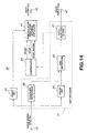
Next, Fig. 16 shows an application example of the present
invention using the aforementioned encoder and decoder.
This application example employs the conventional SCMS
(serial copy management) in combination with analog copy
management according to an embodiment of the invention.
An analog audio input Si inputted from a signal input
terminal 51 is converted by an A/D converter 52 into a digital
signal. The digital signal is supplied via a SW53 to a decoder
54 similar to the aforementioned decoder 11 and 35, for reading
a copy control signal recorded by a gap and a spectrum
diffusion signal. As a result of this reading, a control
signal CNT1 is outputted for controlling a SCMS unit.
The audio signal which has been converted into a digital
signal by the A/D converter 52 is supplied via SW56 to the SCMS
unit 57. Here, if the analog audio signal indicates the first
generation, the SCMS unit 57 rewrites the digital signal
(actually, a sub code area) into a second generation.
The aforementioned digital audio signal is supplied to an
encoder 58 similar to the aforementioned encoder 1 and 20,
where it is controlled by the control signal CNT1 so that a gap
and a spectrum diffusion are overlapped on the audio signal and
the generation information is also rewritten. This result is
recorded by a recording apparatus 59 on a recording medium
tape, disc, or the like) 59a. The audio signal reproduced by
this recording apparatus 59 is converted by a D/A converter 60
into an analog audio signal which is outputted from an output
terminal 61 as an audio output So.
In a case when recording using a conventional digital
interface, the signal is supplied via SW56 to the SCMS unit 57
where the generation is rewritten, and supplied to the encoder
58 where the same information is rewritten on the audio signal.
Moreover, for example, the control signal CNT2 when the
conventional SCMS inhibits copying is combined with the control
signal CNT1 when the copying is inhibited in analog, and their
disjunction as CNT3 will stop recording operation of the
recording apparatus 59.
Here, the rewriting of the generation information can be
carried out in the same way as the conventional SCMS.
Consequently, this application example means extension of the
copy management which has been carried out in the digital
interface over the analog interface.
Moreover, when this signal is reproduced by the recording
apparatus (capable of reproduction) 59, this signal is supplied
via SW53 so that the additional information data recorded on
the audio data will appear on a display unit 62.
Moreover, in the present system, besides the recording
of an additional information using mixture of the
aforementioned spectrum diffusion signal and the gap, there are
some more ways to cope with unauthorized copying through data
revision and destruction.
The gap may be destroyed by a special apparatus. To cope
with this, the gap can be repaired even if destroyed. A
correlation of a high reproductivity is defined between a
feature of an audio signal recorded and the gap position. When
an apparatus having this function is used to reproduce an audio
signal in which the gap has been destroyed, the previous gap
insert position can be restored. If the similar processing
prior to the destruction is carried out according to this, it
is possible to demodulate the spectrum diffusion signal.
Moreover, by allocating the aforementioned sync pattern
for synchronization not on a gap but at a position apart from
the gap, even if the gap is destroyed, it is possible to
demodulate the spectrum diffusion signal by using an apparatus
having a matched filter for the sync pattern for
synchronization.
On the contrary, if the sync pattern for synchronization
is destroyed, a correlation of a high reproductivity is defined
between the feature of the recorded audio signal and the sync
pattern for synchronization, and the sync pattern for
synchronization is restored to demodulate the spectrum
diffusion signal. However, in this case, the time accuracy is
lowered, it is necessary to try several times for the phase.
Moreover, as shown in Fig. 16, according to the present
system, a function other than the copy protection is
realized. This function can be used, for example, as follows.
When the contents are processed with intention to exclude the
copy protection, simultaneously with this or prior to this, the
embedded data such as the music information, the text, and MIDI
is destroyed. Thus, it is possible to make the user unwilling
to carry out an unauthorized act because of the data
destruction.
Moreover, according to the present system, the function
of the additional information provides a copy management
function such as SCMS extended to analog, which can also be
extended to a sub code such as CD/DAT/MD (mini disc) for a
sufficient data rate can be obtained. With this, if a copy
protect recorded in analog is intentionally removed, the
function available on the digital sub code data such as a music
selection and search is also automatically disabled.
Especially if the digital sub code information is also modified
and rewritten, (if the analog data has a higher priority), the
same problem is caused by the medium recorded by an apparatus
using this protect even when mounted on a conventional
apparatus. This makes to lose the convenience of a digital
apparatus and effectively prevents the user from removing the
analog embedded information through an unauthorized revision.
Moreover, the present system utilizes important factors
of the music information such as attack, tempo, and level. By
using this, for example, it is possible to record on an analog
embed a data relating to a control of important portions during
recording and reproduction such servo and sound volume, so as
to be used by the apparatus. If the copy protect recorded in
analog is intentionally removed, the information is also lost,
which disables recording, reproduction, or other operation.
Thus, analog embedded information can be protected.
Recently, there are known techniques for recording a
20-bit data such as HDCD on a 16-bit CD. Among these, there
are those which directly embed the audio data on a digital
data, and the conditions to correctly reproduce these are
written in the analog embedded information so that the
apparatus is affected by that. Thus, from unauthorized
processed music contents, it is impossible to obtain a correct
sound volume or quality.
Moreover, it is possible to control music emphasis. That
is, if the analog embedded information is removed, the data
indicating the emphasis information becomes abnormal. This
brings about an extreme deterioration of the frequency
characteristic of an audio signal. If simultaneously with
this, the emphasis information on the digital sub code is
rewritten in the recording block, the medium recorded by this
apparatus cannot be reproduced correctly even by an apparatus
not having this new copy protect method.
It should be noted that the present invention can also be
applied to a ground wave between a broadcasting station and a
reception apparatus as well as an audio signal transmission by
satellite broadcasting, audio signal transmission by Internet,
and an audio signal transmission between computers.
As has been described above, the present system enables
a short-time synchronization and detection required for a copy
protect and the like. Moreover, by selective writing using a
hearing sense masking, it is possible to overlap on an audio
signal a data minimizing deterioration of the audio signal.
The hardware for detection is a simple one which can be
realized at low costs. Moreover, it is possible to
additionally write a copy generation information, user code,
and the like. Moreover, it is possible to realize more data
channels than in the conventional one. Moreover, it is
possible to correctly read a data even if the audio signal
reproduction speed is varied. Moreover, it is possible to
transfer a data with an audio compression such as
MPEG/ATRAC/AC-3. Moreover, the present system enables a
hybrid method using the gap method in combination,
simultaneously realizing a simple method and a high technique
method, and can be applied to a wide range of product groups.
Moreover, it is possible to extend to analog interface the copy
management and the data transmission in the conventional
digital interface such as SCMS. Moreover, when an additional
information embedded is processed for unauthorized copying, the
recording apparatus and the reproduction apparatus are disabled
to operate correctly, thus inhibiting unauthorized copying.