EP0864965A1 - Information processing apparatus and output apparatus - Google Patents
Information processing apparatus and output apparatus Download PDFInfo
- Publication number
- EP0864965A1 EP0864965A1 EP98201583A EP98201583A EP0864965A1 EP 0864965 A1 EP0864965 A1 EP 0864965A1 EP 98201583 A EP98201583 A EP 98201583A EP 98201583 A EP98201583 A EP 98201583A EP 0864965 A1 EP0864965 A1 EP 0864965A1
- Authority
- EP
- European Patent Office
- Prior art keywords
- data
- information
- printer
- rasterization
- font
- Prior art date
- Legal status (The legal status is an assumption and is not a legal conclusion. Google has not performed a legal analysis and makes no representation as to the accuracy of the status listed.)
- Granted
Links
Images


Classifications
-
- G—PHYSICS
- G06—COMPUTING; CALCULATING OR COUNTING
- G06K—GRAPHICAL DATA READING; PRESENTATION OF DATA; RECORD CARRIERS; HANDLING RECORD CARRIERS
- G06K15/00—Arrangements for producing a permanent visual presentation of the output data, e.g. computer output printers
-
- G—PHYSICS
- G06—COMPUTING; CALCULATING OR COUNTING
- G06F—ELECTRIC DIGITAL DATA PROCESSING
- G06F3/00—Input arrangements for transferring data to be processed into a form capable of being handled by the computer; Output arrangements for transferring data from processing unit to output unit, e.g. interface arrangements
- G06F3/12—Digital output to print unit, e.g. line printer, chain printer
- G06F3/1201—Dedicated interfaces to print systems
- G06F3/1202—Dedicated interfaces to print systems specifically adapted to achieve a particular effect
- G06F3/1203—Improving or facilitating administration, e.g. print management
- G06F3/1204—Improving or facilitating administration, e.g. print management resulting in reduced user or operator actions, e.g. presetting, automatic actions, using hardware token storing data
-
- G—PHYSICS
- G06—COMPUTING; CALCULATING OR COUNTING
- G06F—ELECTRIC DIGITAL DATA PROCESSING
- G06F3/00—Input arrangements for transferring data to be processed into a form capable of being handled by the computer; Output arrangements for transferring data from processing unit to output unit, e.g. interface arrangements
- G06F3/12—Digital output to print unit, e.g. line printer, chain printer
- G06F3/1201—Dedicated interfaces to print systems
- G06F3/1223—Dedicated interfaces to print systems specifically adapted to use a particular technique
- G06F3/1236—Connection management
-
- G—PHYSICS
- G06—COMPUTING; CALCULATING OR COUNTING
- G06F—ELECTRIC DIGITAL DATA PROCESSING
- G06F3/00—Input arrangements for transferring data to be processed into a form capable of being handled by the computer; Output arrangements for transferring data from processing unit to output unit, e.g. interface arrangements
- G06F3/12—Digital output to print unit, e.g. line printer, chain printer
- G06F3/1201—Dedicated interfaces to print systems
- G06F3/1278—Dedicated interfaces to print systems specifically adapted to adopt a particular infrastructure
- G06F3/1284—Local printer device
-
- G—PHYSICS
- G06—COMPUTING; CALCULATING OR COUNTING
- G06K—GRAPHICAL DATA READING; PRESENTATION OF DATA; RECORD CARRIERS; HANDLING RECORD CARRIERS
- G06K15/00—Arrangements for producing a permanent visual presentation of the output data, e.g. computer output printers
- G06K15/02—Arrangements for producing a permanent visual presentation of the output data, e.g. computer output printers using printers
- G06K15/18—Conditioning data for presenting it to the physical printing elements
- G06K15/1848—Generation of the printable image
- G06K15/1856—Generation of the printable image characterized by its workflow
- G06K15/1859—Generation of the printable image characterized by its workflow involving data processing distributed amongst different data processing apparatus
-
- G—PHYSICS
- G06—COMPUTING; CALCULATING OR COUNTING
- G06K—GRAPHICAL DATA READING; PRESENTATION OF DATA; RECORD CARRIERS; HANDLING RECORD CARRIERS
- G06K2215/00—Arrangements for producing a permanent visual presentation of the output data
- G06K2215/0002—Handling the output data
-
- G—PHYSICS
- G06—COMPUTING; CALCULATING OR COUNTING
- G06K—GRAPHICAL DATA READING; PRESENTATION OF DATA; RECORD CARRIERS; HANDLING RECORD CARRIERS
- G06K2215/00—Arrangements for producing a permanent visual presentation of the output data
- G06K2215/0002—Handling the output data
- G06K2215/0005—Accepting output data; Preparing data for the controlling system
- G06K2215/0008—Downloading generic data
-
- G—PHYSICS
- G06—COMPUTING; CALCULATING OR COUNTING
- G06K—GRAPHICAL DATA READING; PRESENTATION OF DATA; RECORD CARRIERS; HANDLING RECORD CARRIERS
- G06K2215/00—Arrangements for producing a permanent visual presentation of the output data
- G06K2215/0002—Handling the output data
- G06K2215/0005—Accepting output data; Preparing data for the controlling system
- G06K2215/0017—Preparing data for the controlling system, e.g. status, memory data
-
- G—PHYSICS
- G06—COMPUTING; CALCULATING OR COUNTING
- G06K—GRAPHICAL DATA READING; PRESENTATION OF DATA; RECORD CARRIERS; HANDLING RECORD CARRIERS
- G06K2215/00—Arrangements for producing a permanent visual presentation of the output data
- G06K2215/0002—Handling the output data
- G06K2215/004—Generic data transformation
- G06K2215/0042—Rasterisation
-
- G—PHYSICS
- G06—COMPUTING; CALCULATING OR COUNTING
- G06K—GRAPHICAL DATA READING; PRESENTATION OF DATA; RECORD CARRIERS; HANDLING RECORD CARRIERS
- G06K2215/00—Arrangements for producing a permanent visual presentation of the output data
- G06K2215/0002—Handling the output data
- G06K2215/0062—Handling the output data combining generic and host data, e.g. filling a raster
- G06K2215/0065—Page or partial page composition
Definitions
- the present invention relates to an information processing apparatus for sending data to an output apparatus such as a printer connected through a bilateral interface, and an output apparatus for receiving data from an information processing apparatus such as a host computer and outputs data in accordance with the input data.
- output information inputted from a host computer is analyzed to develop bit map data as an output data of a printer engine such as a laser beam printer, and a laser beam modulated in accordance with the developed data is scanned and exposed to a photo-conductor drum to record an image.
- a printer engine such as a laser beam printer
- a recording apparatus which can output data WYSIWYG-processed (What You See Is What You Get) by a host computer in accordance with page edit data has also been put into practice.
- the recording apparatus may be of a type which develops the bit map data WYSIWYG-processed by the host computer to a bit map memory to output it, or a type which receives data to be rasterized from the host computer, generates output bit map data by a rasterization function of the recording apparatus and develops it in the bit map memory for outputting it.
- a time from the start of the bit map development of the output information by the host computer to the start of printing by the printer engine is determined by a rasterization time of the host computer.
- the type which receives the data to be rasterized from the host computer generates the output bit map data by the rasterization function of the recording apparatus and develops it to the bit map memory for outputting it
- the time required for the host computer to transfer the output information to the printer is short but the rasterization time of the recording apparatus itself is long so that information received out of image writing synchronization with the printer engine cannot be correctly recorded.
- the present invention provides an information processing apparatus comprising acquiring means for acquiring resource information of a printer connected through a bilateral interface, and determination means for determining a ratio of share to rasterization of information in the data outputted to the printer, to be shared by a rasterizer in the printer.
- the present invention provides an output apparatus comprising receiving means for receiving ratio information of share to rasterize rasterization information in data outputted from an information processing apparatus connected through a bilateral interface, and control means for causing a rasterizer to rasterize the information in accordance with the ratio of share of the rasterization.
- the information processing apparatus and the output apparatus can render uniform the resources and the share of the processing capabilities so that a higher processing performance and an efficient operation of the resources are attained.
- a printer in the embodiment is not to be limited to the laser beam printer or the ink jet printer but it may be other type of printer.
- Fig. 1 shows a sectional view of a construction of a first recording apparatus to which the present invention is applied. It may be a laser beam printer (LBP).
- LBP laser beam printer
- numeral 1500 denotes an LBP main unit which receives print information supplied from an externally connected host computer, stores it, generates a bit map image in accordance with the stored information, and forms an image on a record sheet which is a recording medium.
- Numeral 1501 denotes a console panel having console switches and LED displays arranged thereon
- numeral 1000 denotes a printer control unit for controlling the overall LBP main unit 1500 and analyzing the print information supplied from the host computer.
- the printer control unit 1000 converts the print information to a video signal of the corresponding bit pattern and supplies it to a laser driver 1502, which drives a semiconductor laser 1503, and it turns on and off a laser beam 1504 emitted from a semiconductor laser 1503 in accordance with the input video signal.
- the laser beam 1504 is laterally swung by a rotating polygon mirror 1505 to scan and expose to an electrostatic drum 1506.
- an electrostatic latent image of a character pattern is formed on the electrostatic drum 1506.
- the latent image is developed by a developing unit 1507 arranged around the electrostatic drum 1506 and then transferred to a record sheet.
- the record sheet may be a cut sheet, and cut sheet recording sheets are contained in a sheet cassette 1508 mounted in the LBP 1500, and the sheet is taken into the apparatus by a sheet feed roller 1509 and a transport roller 1511, and it is supplied to the electrostatic drum 1506.
- Fig. 2 shows an external view of a second recording apparatus to which the present invention is applied. It may be an ink jet recording apparatus (IJRA).
- IJRA ink jet recording apparatus
- a carriage HC which engages with a helical groove 5004 of a lead screw 5005 rotated by the forward or backward rotation of a drive motor 5013 through drive force transmission gears 5011 and 5009 has a pin (not shown) and it is reciprocally driven in the directions of arrows a and b.
- An ink jet cartridge IJC is mounted on the carriage HC.
- Numeral 5002 denotes a sheet retainer plate which presses a sheet to a platen 5000 over the range of movement of the carriage.
- Numerals 5007 and 5008 denotes photo-couplers which serves as home position detection means for detecting the presence of a lever 5006 of the carriage in the range to switch the direction of rotation of a motor 5013.
- Numeral 5016 denote a member for supporting a capping member 5022 which caps the entire surface of a recording head
- numeral 5015 denotes suction means for sucking the interior of the cap and it suction-recovers the recording head through an aperture 5023 in the cap
- Numeral 5017 denotes a cleaning blade which is movable back and forth by a member 5019.
- Numeral 5018 denotes a main unit support plate which supports 5017 and 5019.
- Numeral 5012 denotes a lever for starting the suction of the suction recovery, and it is moved with the movement of a cam 5020 which is engaged with the carriage so that a drive force from the drive motor is controlled by known transmission means such as a clutch.
- the capping, cleaning and suction recovery are conducted at the corresponding positions by the action of the lead screw 5005 when the carriage is brought to the home position. It may conduct desired operations at a desired timing.
- Fig. 3 shows a block diagram of a control unit of the second recording apparatus shown in Fig. 2.
- numeral 1700 denotes an interface to which a record signal is applied
- numeral 1701 denotes an MPU
- numeral 1702 denotes a program ROM for storing a control program to be executed by the MPU 1701
- numeral 1703 denotes a DRAM which stores various data (including the record signal record data to be supplied to a head).
- Numeral 1704 denotes a gate array for controlling the supply of the record data to a recording head 1708, and it also controls the transfer of data among the interface 1700, the MPU 1701 and the DRAM 1703.
- Numeral 1710 denotes a carrier motor for carrying the recording head 1708
- numeral 1709 denotes a transport motor for transporting a record sheet
- numeral 1705 denotes a head driver for driving the recording head
- numeral 1706 denotes a motor driver for driving the transport motor 1709
- numeral 1707 denotes a motor driver for driving the carrier motor 1710.
- the recording apparatus of the present embodiment when a record signal is applied from the host computer through the interface 1700, the record signal is converted to print record data by the gate array 1704 and the MPU 1701.
- the motor drivers 1706 and 1707 are driven and the recording head is driven in accordance with the record data sent to the head driver 1705 to print it out.
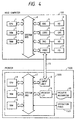
- Fig. 4 shows a block diagram of a configuration of a printer control system in one embodiment of the present invention.
- a laser beam printer (see Fig. 1) is used in the present embodiment.
- the present invention may be applied to any system in which process is made through a network such as a LAN, whether it is a single unit system or a multi-unit system.
- numeral 100 denotes a host computer which has a CPU 1 for processing a document having mixture of graphics, images, characters and tables (including spread sheets) in accordance with a document processing program stored in a ROM 2, and the CPU 1 centrally controls devices connected to a system bus 4.
- a control program for the CPU 1 shown in flow charts of Figs. 6 and 7 is stored in the ROM 2.
- Numeral 3 denotes a RAM which functions as a main memory and a work area of the CPU 1.
- Numeral 5 denotes a keyboard controller (KBC) which controls the key entry from a keyboard 9.
- Numeral 6 denotes a CRT controller (CRTC) which controls the display of a CRT display (CRT) 10.
- Numeral 7 denotes a disk controller (DKC) which controls the access of a hard disk (HD) 11 which stores a boot program, various application programs, font data, a user file and an edit file, and a floppy disk (FD) 12.
- Numeral 8 denotes a printer controller (PRTC) which is connected to the printer 1500 through an interface (bilateral interface) 13 to control the communication with the printer 1500.
- the CPU 1 may develop (rasterize) an outline font to a display information RAM set on the RAM 3 to permit the WYSIWYG processing on the CRT 10. Further, the CPU 1 may open various registered windows in accordance with a command indicated by a mouse cursor, not shown, to process various data.
- the document processing program may be stored in the hard disk 11 or the floppy disk 12 and loaded to the RAM 3 through the DKC 7 for execution.
- numeral 14 denotes a CPU which centrally controls the access to various devices connected to a system bus 17 in accordance with a control program stored in a ROM 15 and outputs an image signal as print data to a print unit (printer engine) 20 connected through a printer interface 19.
- Numeral 19 denoted a RAM which is used as a work area of the CPU 14 and a storage for record information.
- the RAM 16 may be constructed to be expanded in the memory capacity by an optional RAM connected to an expansion port, not shown.
- the printer interface 19 converts the print data to a format compatible to the mechanism of the print unit 20 and outputs it. It may convert parallel data to serial data.
- a plurality of dot fonts of different sizes and outline font data may be stored in the ROM 15 as printer fonts.
- a rasterization program for developing outline font or vector graphics data commanded by the host computer 100 to share to a bit map on a rasterization area of the RAM 16, in parallel with the rasterization on the host computer 100 is stored in the ROM 15.
- a ratio of share of the rasterization is dynamically switched in accordance with the analysis of the rasterization information in the output information which is outputted to the printer 1500 by the host computer 100.
- the printer 1500 and the host computer 100 may conduct the rasterization.
- At least one card slot may be provided to permit the connection of a build-in font as well as an optional card and a card containing a program for interpreting a different printer control language (an emulation card).
- An NVRAM which stores printer mode setting information from a console unit, not shown, may be provided.
- the host computer 100 acquires the resource date from the printer 1500, and when a print job occurs, the CPU 1 analyzes the print job in accordance with the resource data of the printer 1500 to dynamically determine the ratio of share of the parallel processing between the first rasterizer (the function of the CPU 1) and the second rasterizer (the function of the CPU 14), and the second rasterizer or the first rasterizer parallelly processes the rasterization information in the print job in accordance with the determined ratio of share of the parallel processing so that the print job is efficiently processed while the shares to the data processing of the printer and the host computer are rendered uniform.
- the first rasterizer the function of the CPU 1
- the second rasterizer the function of the CPU 14
- the CPU 1 analyzes the font size in the print job based on the resource data of the printer to dynamically determine the ratio of share of the parallel processing by the first rasterizer and the second rasterizer so that the host computer and the printer functionally share the rasterization for the specific types of fonts.
- the CPU 1 further analyzes the quantity of outline interpolation information in the print job based on the resource data of the printer to dynamically determine the ratio of share of the parallel processing of the first rasterizer and the second rasterizer so that the rasterization corresponding to the number of interpolations in the outline information is functionally shared by the host computer and the printer.
- the resource data include resource/processing capability information such as an inquiry to the printer 1500, the presence or absence of a draw function to each draw unit of a line or a circle of the printer by the reference to a definition file on the host computer 100, a draw process time, the presence or absence of the rasterization function of the outline font and a rasterization time, and they are stored in a memory such as the RAM 16.
- the CPU 1 analyzes all or a portion of those information to dynamically determine the ratio of share of the parallel processing of the first rasterizer and the second rasterizer.
- the CPU 1 dynamically switches the ratio of share of the parallel processing for each page of the output edit information (characters, graphics, tables and images).
- time data required for the printer 1500 to rasterize a predetermined size of outline font is stored in the memory such as the RAM 16 as table data, and when the size of the outline font of the record data is equal to the stored size, the table data is used, and when they are not equal, the table data of the outline font of the record data is corrected to accumulate the rasterization times of the respective characters to determine the ratio of share of the rasterization of the host computer 100 and the printer 1500.
- the number of interpolation points (for example, the interpolation by a bezie curve) may be taken into consideration to attain more accurate calculation of the processing time.
- a plurality of tables for rasterization may be provided in the memory such as the RAM 16 so that the rasterization time is more accurately calculated by taking the differences in the languages and the resolution power into account.
- the rasterization of the font may be distributed to the host computer 100 and the printer 1500 in accordance with the performances thereof.
- One font may be transferred to the printer 1500 in the form of bit map to conduct the rasterization by the host Computer 100 and the remaining fonts may be transferred to the printer 1500 in the form of outline for the rasterization by the CPU 14.
- the host computer 100 transfers only the character codes and the attributes thereof to the printer 1500 and quickly terminates the data transfer from the host computer to shorten the time to release the host computer.
- a portion or all of the band may be assigned to the host computer 100 to prevent a print error of the printer 2500 due to the variation of the share of the record information processing.
- Fig. 5 shows a diagram of a data process path between the printer 1500 and the host computer 100 shown in Fig. 4.
- numeral 101 denotes an application being executed, which may be a DTP processing program.
- Numeral 103 denotes a data analyzer which analyzes a print job for each page, classifies it to an outline font or the like (see Fig. 7 to be explained later), determines the share of the rasterization, and directs data to be processed to the font 103, a font rasterizer (which functions as a first rasterizer) 104, a graphics rasterizer (which functions as the first rasterizer) 105 and a page data generator 106, which combines output data from the data analyzer 102, the graphics rasterizer 105, the font 103 and the font rasterizer 104.
- Numerals 107 and 201 denote input/output handlers which control the input/output of the printer 1500 and the host computer 100.
- Numeral 202 denotes a rasterizer which develops the rasterized data to a bit map.
- Numeral 203 denotes a rasterizer which rasterizes a font by referring a memory 204 which stores the outline data by referring the received outline font or based on the received character codes.
- Numeral 205 denotes a print control unit which controls the transfer of the bit map data outputted from the rasterizer 202 to the print unit 20 (see Fig. 4).
- A-N denote data process paths.
- the rasterization of the font may be distributed in accordance with the performances of the host computer 100 and the printer 1500, and one font may be processed by the rasterization by the host computer 100 and transferred to the printer 1500 (paths C-H-J-K) in the form of bit map and the remaining fonts may be transferred (paths D-G-J-K) to the printer 1500 in the form of outline for the rasterization by the font rasterizer 203.
- Fig. 6 shows a flow chart of a rasterization parallel process of the printer 1500 and the host computer 100 shown in Fig. 4.
- Numerals (1) to (6) denote steps of the host computer 100
- numerals (11) to (14) denote steps of the printer 1500.
- Analysis and classification routine of the font data in the print job is executed (1) in accordance with the flow chart shown in Fig. 7 to determine the share of processing in accordance with the processing capability (2).
- the outline data of the font or the character code of the outline font is sent to the printer 1500 (3).
- the process of the step (11) is parallelly started. The process by the host computer 100 is described below.
- the rasterization (scaling) on the font data assigned to the host computer 100 is executed (4), and the developed bit map font is sent to the printer 1500 (5). As a result, the process of the step (12) is simultaneously started.
- the page data is then sent to the printer 1500 (6), and the process is terminated.
- the font data assigned from the host computer 100 is received in the step (3), the received font is scaled (rasterized) and it is registered in the RAM 16 (11).
- the bit map data is received from the host computer 100 in the step (5), the received bit map data is registered in the RAM 16 (12).
- the page data is received from the host computer 100 in the step (6), the received page data is stored in the RAM 16 (13), and the rasterizer 202 page-rasterizes it by referring the data in the RAM 16 and transfers the page-rasterized printer data to the print control unit 205 (14), and the process is terminated.
- the host computer acquires the resource data of the printer, analyzes the print job in accordance with the resource data, and determines the ratio of share of the rasterization of the printer and the host computer to the rasterization information of the print job, and the host computer and/or the printer parallelly rasterizes the information extracted from the print job in accordance with the determined ratio of share of the rasterization so that the shares of the rasterization of the information by the printer and the host computer are rendered uniform.
- the resource data processing program which the host computer 100 analyzes need not be stored in the ROM 2 if it is stored in the hard disk 11 of the host computer 100 by the floppy disk 12 and can be executed by the print driver.
- Fig. 7 shows a flow chart of a detail of the font rasterization/analysis/classification routine shown in Fig. 6.
- Numerals (1) to (11) denote steps.
- the data analyzer 102 searches the font data of the print job (1) to determine whether the data still exists or not (2), and if the decision is NO, the process is terminated, and if the decision is YES, whether the searched data matches to the bit map font of the printer 1500 or not is determined (3). If the decision is YES, the font is classified to the bit map code of the printer 1500 (8), and the process returns to the step (1).
- step (3) determines whether the searched data matches to the outline font in the printer 1500 or not is determined, (4), and if the decision is YES, the font is classified to the outline code of the printer 1500 (9), and the process returns to the step (1).
- step (5) determines whether the searched data is the outline font or not. If the decision is NO, the searched data is classified to the bit map data (7) and the process returns to the step (1).
- the font data in the print job is classified into one of the following five types by a flow chart of Fig. 7.
- the font data classified to the bit map code in the step (8) has the bit map font data in the printer 1500.
- This, the character codes and the attributes are sent from the data analyzer 102 to the printer 1500 and they are processed by the rasterizer 202 (paths B-J-K).
- the font data classified to the outline code in the step (9) has the outline font data in the printer 1500.
- the character codes and the attributes are sent from the data analyzer 102 to the printer 1500 and they are converted to the bit map font data by the font rasterizer on the printer 1500 and processed by the rasterizer 202 (paths B-J-K-M-N), or they are converted to the bit map font data by the font rasterizer 104 on the host computer 100 and the converted bit map font data is sent to the printer 1500 and processed by the rasterizer 202 (paths C-H-J-K).
- the font data classified to the outline data in the step (10) has the font rasterizer 203 on the printer 1500 but does not have the outline font data.
- the character codes and the attributes are delivered from the data analyzer 102 to the font 103 and the corresponding outline font data is sent to the printer 1500, and they are converted to the bit map font data by the font rasterizer 203 on the printer 1500 and processed by the rasterizer 202 (paths D-G-K-M), or they are converted to the bit map font data by the font rasterizer 104 on the host computer 100 and the converted bit map font data is sent to the printer 1500 and processed by the rasterizer 202 (paths C-H-J-K).
- the font data classified to the host scaling in the step (11) does not have the font rasterizer in the printer 1500. Accordingly, the font data is converted to the bit map data by the font rasterizer 104 on the host computer 100 and the converted bit map data is sent to the printer 1500 and processed by the rasterizer (paths C-H-J-K).
- the font data classified to the bit map data in the step (7) does not have the bit map font data in the printer 1500. Accordingly, the bit map font data on the host computer 100 is sent to the printer 1500 and processed by the rasterizer 202.
- the font data classified to the host scaling (step (11)) of the five types of the classified font data is font-rasterized by the host computer 100, and the font data classified to the outline code (step (9)) and the outline data (step (10)) are font-rasterized by the host computer 100 or the printer 1500 in accordance with the font rasterization resource (capability) of the host computer 100 and the printer 1500.
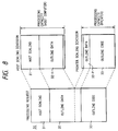
- Fig. 8 shows a diagram of a ratio of share of the rasterization of the printer 1500 and the host computer 100 shown in Fig. 4. It shows a share status of the rasterization when the printer 1500 has the rasterizer 202 which can process the rasterized data and the font rasterizer 203 which can execute the font rasterization in accordance with the outline font data.
- numeral 30 denotes a font rasterization process in the print job, which comprises host computer scaling 31 which the host computer 100 scales, outline data 32 (including graphics and font) which the printer 1500 can rasterize, and outline code 33.
- the outline data 32 is divided to outline data 32-H which is processed by the host computer 100 and outline data 32-P which is processed by the printer 1500, and the outline code 33 is directly processed by the font rasterizer 203 of the printer 1500.
- the host scaling 31 is first processed and the remaining outline data 32 and the outline code 33 are divided into the host scaling process and the printer scaling process including the host scaling 31 in accordance with the host processing capability and the printer processing capability.
- the outline data is divided.
- the outline code 33 is large, the outline code may be divided.
- the font information is classified to the host scaling 31 and the outline code 33, and when there is no outline font data in the printer 1500 and the font rasterizer 203 which can process the outline font data on the host computer 100 is provided, the font data is classified to the host scaling 31 and the outline data 32. In any case, it is divided to the host scaling process and the printer scaling process including the host scaling 31 in accordance with the host processing capability and the printer processing capability.
- the host computer 100 acquires the resource data of the printer 1500 and dynamically determines the ratio of share of the rasterization for each printer job so that the share of the data processing of the host computer 100 and the printer 1500 is rendered uniform and the time from the input of the print command to the start of the sheet feed from the printer 1500 is shortened.
- the font rasterization of the outline font is shared by the host computer and the printer although the rasterization of other than font such as the rasterization of the vector graphics or the expansion and the compaction of the bit image may also be shared.
- the timing to acquire the resource data (for example, the table data) is not referred although the host computer 100 may store the resource data in the hard disk 11 as a temporary file at a timing communicatable with the printer 1500, or the resource data may be read from the printer 1500 at the time of the print command and stored as a temporary file, or it may be previously stored in the HD 11 of the host computer 100.
- the host computer acquires the resource data of the printer, analyzes the print job based on the resource data, and determines the ratio of share of the rasterization of the printer and the host computer to the rasterization information of the print job, and the host computer and/or the printer parallelly rasterize the information extracted from the print job in accordance with the determined ratio of share of the rasterization so that the share of the rasterization of the printer and the host Computer is rendered uniform.
- the rasterization information including the font data and the vector graphics data is parallelly rasterized by the host computer and/or the printer so that the share of the rasterization of the host computer and the printer is rendered uniform.
- the host computer acquires the resource data of the printer, and when the print job is generated, it analyzes the print job based on the resource data of the printer to dynamically determine the ratio of share of the parallel processing of the first rasterizer and the second rasterizer, and the second rasterizer or the first rasterizer parallelly share the rasterization of the information in accordance with the determined ratio of share of the parallel processing so that the print job is efficiently processed while the share of the data processing of the printer and the host computer is rendered uniform.
- the print job is efficiently processed while the share of the data processing of the printer and the host computer is rendered uniform.
- the rasterization of the specific types of font can be functionally shared by the host computer and the printer.
- the rasterization process corresponding to the number of interpolations in the outline information can be functionally shared by the host computer and the printer.
Abstract
Description
Claims (33)
- An information processing apparatus (100) which transmits job data to an electronic apparatus (1500), said information processing apparatus comprising:means (1) for analyzing job data;means (1) for determining a processing sharing ratio of the job data between the electronic apparatus and said information processing apparatus on the basis of a data processing capability of the electronic apparatus and an analysis result by said analyzing means, the processing sharing ratio being variably job data by job data; andmeans (1) for controlling transmission of the job data to be processed by the electronic apparatus on the basis of the processing sharing ratio determined by said determining means.
- Apparatus as claimed in claim 1 wherein the determining means is operable to analyze the job data and to determine the sharing ratio between first and second portions of the job data such that the time taken for processing the job data is substantially minimised.
- Apparatus as claimed in claim 2 wherein the electronic apparatus comprises a printer (1500), the job data comprises print information, and the sharing ratio comprises a rasterizing sharing ratio.
- Apparatus as claimed in claim 3 wherein the print information comprises font data and vector graphics data.
- Apparatus as claimed in claim 4 wherein the determining means is operable to analyze the amount of font data in each page of the print information based on the data processing capability of the printer and to dynamically determine the rasterizing sharing ratio.
- Apparatus as claimed in any of claims 4 and 5 wherein the determining means is operable to analyze the amount of vector graphics data in each page of the print information based on the data processing capability and to dynamically determine the rasterizing sharing ratio.
- Apparatus as claimed in any of claims 3 to 6 wherein the data processing capability is defined by resource information which includes information as to the presence or absence of a rasterization function of the printer.
- Apparatus as claimed in any of claims 3 to 7 wherein the data processing capability is defined by resource information which includes data indicating the time taken by the second rasterizer to rasterize predetermined amounts of print data.
- Apparatus as claimed in of claims 3 to 8 wherein the information processing apparatus is a host computer.
- Apparatus as claimed in any of claims 3 to 9 wherein the printer is a laser beam printer (1500).
- A method of transmitting job data from an information processing apparatus to an electronic apparatus, said method comprising the steps of:analyzing the job data;determining a processing sharing ratio of the job data between the electronic apparatus and said information processing apparatus on the basis of a data processing capability of the electronic apparatus and an analysis result by said analyzing means, the processing sharing ratio being variably job data by job data; andcontrolling transmission of the job data to be processed by the electronic apparatus on the basis of the processing sharing ratio determined by said determining step.
- A method as claimed in claim 11 wherein the determining step analyzes the job data and determines the sharing ratio between first and second portions of the job data such that the time taken for processing the job data is substantially minimised.
- A method as claimed in claim 12 wherein the electronic apparatus comprises a printer (1500), the job data comprises print information, and the processing step comprises rasterizing the print information according to rasterizing sharing ratio.
- A method as claimed in claim 13 wherein the print information comprises font data and vector graphics data.
- A method as claimed in claim 14 wherein the determining step analyzes the amount of font data in each page of the print information based on the resource information and dynamically determines the rasterizing sharing ratio.
- A method as claimed in any of claims 14 and 15 wherein the determining step analyzes the amount of vector graphics data in each page of the print information based on the resource information and dynamically determines the rasterizing sharing ratio.
- A method as claimed in any of claims 13 to 16 wherein the resource information includes information as to the presence or absence of a rasterization function of the printer.
- A method as claimed in any of claims 3 to 17 wherein the resource information includes data indicating the time taken by the second rasterizer to rasterize predetermined amounts of print data.
- A method as claimed in any of claims 13 to 18 wherein the information processing apparatus is a host computer.
- A method as claimed in any of claims 13 to 19 wherein the printer is a laser beam printer (1500).
- A method as claimed in any of claims 13 to 20 comprising the further steps of:receiving through the bilateral interface (13) control information from the control means (1); andrasterizing print information by operation of the second rasterizer (202) in accordance with the control information.
- An information processing apparatus comprising:acquiring means for acquiring resource information of a printer connected through a bilateral interface; anddetermination means for determining a ratio of share of rasterization of information in the data outputted to said printer, to be shared by a rasterizer in said printer.
- An information processing apparatus according to Claim 22, wherein said resource information includes processing capability information such as the presence or absence of the rasterization information of said printer and a rasterization time.
- An information processing apparatus according to Claim 22, wherein said rasterization information includes font data and vector graphics data.
- An information processing apparatus according to Claim 22, wherein said rasterizer generates bit map data in accordance with the rasterization information.
- An information processing apparatus according to Claim 22, further comprising a rasterizer for processing the rasterization information, wherein the rasterizer in said printer and/or the second rasterizer parallelly share the processing.
- An information processing apparatus according to Claim 22, wherein said determination means analyzes a font size in the data to be outputted base on the resource information of said printer to dynamically determine the ratio of share of the rasterization.
- An information processing apparatus according to Claim 22, wherein said determination means analyzes the amount of outline interpolation information in the data to be outputted based on the resource information of said printer to dynamically determine the ratio of share of the rasterization.
- An information processing apparatus according to Claim 22, wherein said information processing apparatus is a host computer.
- An output apparatus comprising:receiving means for receiving ratio information of share of rasterization of rasterization information in data outputted from an information processing apparatus connected through a bilateral interface; andcontrol means for causing a rasterizer to rasterize the rasterization information in accordance with the ratio of share of the rasterization.
- An output apparatus according to Claim 30, wherein the rasterization information includes font data and vector graphics data.
- An output apparatus according to Claim 30, wherein said information processing apparatus is a host computer.
- An output apparatus according to Claim 30, wherein said output apparatus is a laser beam printer.
Applications Claiming Priority (4)
| Application Number | Priority Date | Filing Date | Title |
|---|---|---|---|
| JP4186358A JP2939059B2 (en) | 1992-06-19 | 1992-06-19 | Information processing apparatus, electronic device, and information processing method |
| JP186358/92 | 1992-06-19 | ||
| JP18635892 | 1992-06-19 | ||
| EP19930304726 EP0575169B1 (en) | 1992-06-19 | 1993-06-17 | Information processing apparatus and output apparatus |
Related Parent Applications (1)
| Application Number | Title | Priority Date | Filing Date |
|---|---|---|---|
| EP19930304726 Division EP0575169B1 (en) | 1992-06-19 | 1993-06-17 | Information processing apparatus and output apparatus |
Publications (2)
| Publication Number | Publication Date |
|---|---|
| EP0864965A1 true EP0864965A1 (en) | 1998-09-16 |
| EP0864965B1 EP0864965B1 (en) | 2003-09-17 |
Family
ID=16186976
Family Applications (3)
| Application Number | Title | Priority Date | Filing Date |
|---|---|---|---|
| EP98201583A Expired - Lifetime EP0864965B1 (en) | 1992-06-19 | 1993-06-17 | Information processing apparatus and output apparatus |
| EP19930304726 Expired - Lifetime EP0575169B1 (en) | 1992-06-19 | 1993-06-17 | Information processing apparatus and output apparatus |
| EP98201602A Expired - Lifetime EP0864966B1 (en) | 1992-06-19 | 1993-06-17 | Imformation processing apparatus and output apparatus |
Family Applications After (2)
| Application Number | Title | Priority Date | Filing Date |
|---|---|---|---|
| EP19930304726 Expired - Lifetime EP0575169B1 (en) | 1992-06-19 | 1993-06-17 | Information processing apparatus and output apparatus |
| EP98201602A Expired - Lifetime EP0864966B1 (en) | 1992-06-19 | 1993-06-17 | Imformation processing apparatus and output apparatus |
Country Status (4)
| Country | Link |
|---|---|
| EP (3) | EP0864965B1 (en) |
| JP (1) | JP2939059B2 (en) |
| DE (3) | DE69332864T2 (en) |
| SG (1) | SG65579A1 (en) |
Cited By (4)
| Publication number | Priority date | Publication date | Assignee | Title |
|---|---|---|---|---|
| WO2001029648A2 (en) * | 1999-10-19 | 2001-04-26 | Electronics For Imaging, Inc. | Method and apparatus for smart job ticket processing for print streams |
| GB2395332A (en) * | 2002-10-17 | 2004-05-19 | Hewlett Packard Development Co | Printer instruction processing |
| US6866434B2 (en) * | 2000-11-11 | 2005-03-15 | Best Gmbh | Method of monitoring at least one printing parameter of a printer, and printing system |
| US7999951B2 (en) | 2006-12-29 | 2011-08-16 | Sharp Laboratories Of America | Direct print handling of native and non-native data formats |
Families Citing this family (2)
| Publication number | Priority date | Publication date | Assignee | Title |
|---|---|---|---|---|
| JP3461243B2 (en) * | 1995-06-20 | 2003-10-27 | キヤノン株式会社 | Information processing apparatus and information processing method |
| US7605939B2 (en) | 2003-10-14 | 2009-10-20 | Canon Kabushiki Kaisha | Information processing apparatus for forming raster image data based on different printing commands, control method therefor, and computer-readable medium storing a computer program implementing the control thereof |
Citations (3)
| Publication number | Priority date | Publication date | Assignee | Title |
|---|---|---|---|---|
| EP0427466A2 (en) * | 1989-11-01 | 1991-05-15 | Xerox Corporation | Computer plotter control |
| EP0432896A2 (en) * | 1989-11-15 | 1991-06-19 | International Business Machines Corporation | Conversion of image data stream into output data for printing or displaying the image |
| US5075875A (en) * | 1990-04-20 | 1991-12-24 | Acuprint, Inc. | Printer control system |
Family Cites Families (1)
| Publication number | Priority date | Publication date | Assignee | Title |
|---|---|---|---|---|
| JPH01277929A (en) * | 1988-04-28 | 1989-11-08 | Toshiba Corp | Information processor |
-
1992
- 1992-06-19 JP JP4186358A patent/JP2939059B2/en not_active Expired - Fee Related
-
1993
- 1993-06-17 DE DE1993632864 patent/DE69332864T2/en not_active Expired - Lifetime
- 1993-06-17 SG SG1996006859A patent/SG65579A1/en unknown
- 1993-06-17 EP EP98201583A patent/EP0864965B1/en not_active Expired - Lifetime
- 1993-06-17 DE DE1993633212 patent/DE69333212T2/en not_active Expired - Lifetime
- 1993-06-17 EP EP19930304726 patent/EP0575169B1/en not_active Expired - Lifetime
- 1993-06-17 EP EP98201602A patent/EP0864966B1/en not_active Expired - Lifetime
- 1993-06-17 DE DE1993622314 patent/DE69322314T2/en not_active Expired - Lifetime
Patent Citations (3)
| Publication number | Priority date | Publication date | Assignee | Title |
|---|---|---|---|---|
| EP0427466A2 (en) * | 1989-11-01 | 1991-05-15 | Xerox Corporation | Computer plotter control |
| EP0432896A2 (en) * | 1989-11-15 | 1991-06-19 | International Business Machines Corporation | Conversion of image data stream into output data for printing or displaying the image |
| US5075875A (en) * | 1990-04-20 | 1991-12-24 | Acuprint, Inc. | Printer control system |
Cited By (7)
| Publication number | Priority date | Publication date | Assignee | Title |
|---|---|---|---|---|
| WO2001029648A2 (en) * | 1999-10-19 | 2001-04-26 | Electronics For Imaging, Inc. | Method and apparatus for smart job ticket processing for print streams |
| WO2001029648A3 (en) * | 1999-10-19 | 2002-01-17 | Electronics For Imaging Inc | Method and apparatus for smart job ticket processing for print streams |
| US6519053B1 (en) | 1999-10-19 | 2003-02-11 | Electronics For Imaging, Inc. | Method and apparatus for smart job ticket processing for print streams |
| US6866434B2 (en) * | 2000-11-11 | 2005-03-15 | Best Gmbh | Method of monitoring at least one printing parameter of a printer, and printing system |
| GB2395332A (en) * | 2002-10-17 | 2004-05-19 | Hewlett Packard Development Co | Printer instruction processing |
| GB2395332B (en) * | 2002-10-17 | 2006-02-15 | Hewlett Packard Development Co | Printer instruction processing |
| US7999951B2 (en) | 2006-12-29 | 2011-08-16 | Sharp Laboratories Of America | Direct print handling of native and non-native data formats |
Also Published As
| Publication number | Publication date |
|---|---|
| EP0575169B1 (en) | 1998-12-02 |
| DE69322314D1 (en) | 1999-01-14 |
| JPH0691990A (en) | 1994-04-05 |
| DE69333212D1 (en) | 2003-10-23 |
| DE69322314T2 (en) | 1999-05-20 |
| EP0864966B1 (en) | 2003-04-09 |
| EP0575169A1 (en) | 1993-12-22 |
| DE69332864D1 (en) | 2003-05-15 |
| SG65579A1 (en) | 1999-06-22 |
| EP0864965B1 (en) | 2003-09-17 |
| EP0864966A2 (en) | 1998-09-16 |
| JP2939059B2 (en) | 1999-08-25 |
| DE69332864T2 (en) | 2003-12-11 |
| EP0864966A3 (en) | 1999-09-15 |
| DE69333212T2 (en) | 2004-07-08 |
Similar Documents
| Publication | Publication Date | Title |
|---|---|---|
| EP0575167B1 (en) | Information processing apparatus and output apparatus | |
| US6611347B1 (en) | Print control apparatus, print control method, storage medium, and computer readable program performing a form overlay process | |
| US7229224B2 (en) | Printing system and printing apparatus | |
| US20010028464A1 (en) | Output control method and apparatus, and output system | |
| US7081970B2 (en) | Information processing apparatus | |
| JP3634447B2 (en) | Image processing apparatus and method | |
| EP0684546B1 (en) | Printing apparatus, printing system, and a method for acquiring character resources of the printing system | |
| EP0864965B1 (en) | Information processing apparatus and output apparatus | |
| US6750980B1 (en) | Information processing apparatus and output apparatus | |
| US6310693B1 (en) | Printing control apparatus and method, and printing system for reducing processing overhead | |
| US6862100B2 (en) | Determining a type of print data to be sent to a printer based on the number of unprocessed files residing in a print queue | |
| US20040070784A1 (en) | Methods, computer media and devices for processing compressed data intended for printing | |
| JP3281327B2 (en) | Information processing apparatus and information processing method | |
| JP3183862B2 (en) | Information processing apparatus and data processing method of information processing apparatus | |
| US6397265B1 (en) | Print control apparatus for communicating with a selected external apparatus to control a printer | |
| JP3202841B2 (en) | Printing apparatus, printing system, and printing control method | |
| JP3056948B2 (en) | PRINTING APPARATUS, CONTROLLER THEREOF, AND METHOD OF CONTROLLING PRINTING APPARATUS | |
| JPH09295432A (en) | Printer and print controlling method | |
| JP3320229B2 (en) | Image forming method and printer control system | |
| JPH07104954A (en) | Printer and control method therefor | |
| JP3610307B2 (en) | Image forming method and apparatus | |
| JP3495877B2 (en) | Printer control system, printer control device and their methods | |
| JPH064241A (en) | Method and device for printing | |
| JPH10333843A (en) | Output control device, method therefor, and output system | |
| JPH08147117A (en) | Output method |
Legal Events
| Date | Code | Title | Description |
|---|---|---|---|
| PUAI | Public reference made under article 153(3) epc to a published international application that has entered the european phase |
Free format text: ORIGINAL CODE: 0009012 |
|
| AC | Divisional application: reference to earlier application |
Ref document number: 575169 Country of ref document: EP |
|
| AK | Designated contracting states |
Kind code of ref document: A1 Designated state(s): DE FR GB IT |
|
| 17P | Request for examination filed |
Effective date: 19990201 |
|
| 17Q | First examination report despatched |
Effective date: 20001031 |
|
| GRAG | Despatch of communication of intention to grant |
Free format text: ORIGINAL CODE: EPIDOS AGRA |
|
| GRAG | Despatch of communication of intention to grant |
Free format text: ORIGINAL CODE: EPIDOS AGRA |
|
| GRAG | Despatch of communication of intention to grant |
Free format text: ORIGINAL CODE: EPIDOS AGRA |
|
| GRAH | Despatch of communication of intention to grant a patent |
Free format text: ORIGINAL CODE: EPIDOS IGRA |
|
| GRAH | Despatch of communication of intention to grant a patent |
Free format text: ORIGINAL CODE: EPIDOS IGRA |
|
| GRAA | (expected) grant |
Free format text: ORIGINAL CODE: 0009210 |
|
| AC | Divisional application: reference to earlier application |
Ref document number: 0575169 Country of ref document: EP Kind code of ref document: P |
|
| AK | Designated contracting states |
Kind code of ref document: B1 Designated state(s): DE FR GB IT |
|
| REG | Reference to a national code |
Ref country code: GB Ref legal event code: FG4D |
|
| REF | Corresponds to: |
Ref document number: 69333212 Country of ref document: DE Date of ref document: 20031023 Kind code of ref document: P |
|
| ET | Fr: translation filed | ||
| PLBE | No opposition filed within time limit |
Free format text: ORIGINAL CODE: 0009261 |
|
| STAA | Information on the status of an ep patent application or granted ep patent |
Free format text: STATUS: NO OPPOSITION FILED WITHIN TIME LIMIT |
|
| 26N | No opposition filed |
Effective date: 20040618 |
|
| PGFP | Annual fee paid to national office [announced via postgrant information from national office to epo] |
Ref country code: GB Payment date: 20110621 Year of fee payment: 19 |
|
| PGFP | Annual fee paid to national office [announced via postgrant information from national office to epo] |
Ref country code: IT Payment date: 20110608 Year of fee payment: 19 |
|
| PGFP | Annual fee paid to national office [announced via postgrant information from national office to epo] |
Ref country code: FR Payment date: 20110713 Year of fee payment: 19 |
|
| PGFP | Annual fee paid to national office [announced via postgrant information from national office to epo] |
Ref country code: DE Payment date: 20110630 Year of fee payment: 19 |
|
| GBPC | Gb: european patent ceased through non-payment of renewal fee |
Effective date: 20120617 |
|
| PG25 | Lapsed in a contracting state [announced via postgrant information from national office to epo] |
Ref country code: IT Free format text: LAPSE BECAUSE OF NON-PAYMENT OF DUE FEES Effective date: 20120617 |
|
| REG | Reference to a national code |
Ref country code: FR Ref legal event code: ST Effective date: 20130228 |
|
| REG | Reference to a national code |
Ref country code: DE Ref legal event code: R119 Ref document number: 69333212 Country of ref document: DE Effective date: 20130101 |
|
| PG25 | Lapsed in a contracting state [announced via postgrant information from national office to epo] |
Ref country code: DE Free format text: LAPSE BECAUSE OF NON-PAYMENT OF DUE FEES Effective date: 20130101 Ref country code: FR Free format text: LAPSE BECAUSE OF NON-PAYMENT OF DUE FEES Effective date: 20120702 Ref country code: GB Free format text: LAPSE BECAUSE OF NON-PAYMENT OF DUE FEES Effective date: 20120617 |