EP0865106B1 - Combination of electrical connectors - Google Patents
Combination of electrical connectors Download PDFInfo
- Publication number
- EP0865106B1 EP0865106B1 EP98104217A EP98104217A EP0865106B1 EP 0865106 B1 EP0865106 B1 EP 0865106B1 EP 98104217 A EP98104217 A EP 98104217A EP 98104217 A EP98104217 A EP 98104217A EP 0865106 B1 EP0865106 B1 EP 0865106B1
- Authority
- EP
- European Patent Office
- Prior art keywords
- plug
- pins
- receptacles
- connector
- elements
- Prior art date
- Legal status (The legal status is an assumption and is not a legal conclusion. Google has not performed a legal analysis and makes no representation as to the accuracy of the status listed.)
- Expired - Lifetime
Links
Images
Classifications
-
- H—ELECTRICITY
- H01—ELECTRIC ELEMENTS
- H01R—ELECTRICALLY-CONDUCTIVE CONNECTIONS; STRUCTURAL ASSOCIATIONS OF A PLURALITY OF MUTUALLY-INSULATED ELECTRICAL CONNECTING ELEMENTS; COUPLING DEVICES; CURRENT COLLECTORS
- H01R27/00—Coupling parts adapted for co-operation with two or more dissimilar counterparts
- H01R27/02—Coupling parts adapted for co-operation with two or more dissimilar counterparts for simultaneous co-operation with two or more dissimilar counterparts
-
- H—ELECTRICITY
- H01—ELECTRIC ELEMENTS
- H01R—ELECTRICALLY-CONDUCTIVE CONNECTIONS; STRUCTURAL ASSOCIATIONS OF A PLURALITY OF MUTUALLY-INSULATED ELECTRICAL CONNECTING ELEMENTS; COUPLING DEVICES; CURRENT COLLECTORS
- H01R13/00—Details of coupling devices of the kinds covered by groups H01R12/70 or H01R24/00 - H01R33/00
- H01R13/40—Securing contact members in or to a base or case; Insulating of contact members
- H01R13/42—Securing in a demountable manner
- H01R13/436—Securing a plurality of contact members by one locking piece or operation
- H01R13/4361—Insertion of locking piece perpendicular to direction of contact insertion
-
- H—ELECTRICITY
- H01—ELECTRIC ELEMENTS
- H01R—ELECTRICALLY-CONDUCTIVE CONNECTIONS; STRUCTURAL ASSOCIATIONS OF A PLURALITY OF MUTUALLY-INSULATED ELECTRICAL CONNECTING ELEMENTS; COUPLING DEVICES; CURRENT COLLECTORS
- H01R13/00—Details of coupling devices of the kinds covered by groups H01R12/70 or H01R24/00 - H01R33/00
- H01R13/62—Means for facilitating engagement or disengagement of coupling parts or for holding them in engagement
- H01R13/627—Snap or like fastening
- H01R13/6271—Latching means integral with the housing
- H01R13/6273—Latching means integral with the housing comprising two latching arms
-
- H—ELECTRICITY
- H01—ELECTRIC ELEMENTS
- H01R—ELECTRICALLY-CONDUCTIVE CONNECTIONS; STRUCTURAL ASSOCIATIONS OF A PLURALITY OF MUTUALLY-INSULATED ELECTRICAL CONNECTING ELEMENTS; COUPLING DEVICES; CURRENT COLLECTORS
- H01R2107/00—Four or more poles
-
- H—ELECTRICITY
- H01—ELECTRIC ELEMENTS
- H01R—ELECTRICALLY-CONDUCTIVE CONNECTIONS; STRUCTURAL ASSOCIATIONS OF A PLURALITY OF MUTUALLY-INSULATED ELECTRICAL CONNECTING ELEMENTS; COUPLING DEVICES; CURRENT COLLECTORS
- H01R2201/00—Connectors or connections adapted for particular applications
- H01R2201/26—Connectors or connections adapted for particular applications for vehicles
Landscapes
- Details Of Connecting Devices For Male And Female Coupling (AREA)
- Connector Housings Or Holding Contact Members (AREA)
- Coupling Device And Connection With Printed Circuit (AREA)
Description
Die Erfindung betrifft einen Steckverbinder zum Verbinden elektrischer Schaltungen oder zum Anschluß elektrischer Schaltungen an zugehörige elektrische Spannungen. Derartige Stecker besitzen regelmäßig ein Kunststoffgehäuse, in dem Metallkontakte angeordnet sind. Metallkontakte können als Steckhülsen oder als Steckerstifte ausgestaltet sein. Für eine Steckverbindung, bei der zwei Steckverbinder ineinandergesteckt werden (nachfolgend vielfach kurz Stecker genannt), ist dabei regelmäßig der eine Stecker mit Steckerstiften versehen, während der zugehörige zweite Stecker Steckhülsen aufweist.The invention relates to a connector for connecting electrical circuits or for connecting electrical Circuits to associated electrical voltages. such Plugs regularly have a plastic housing in which Metal contacts are arranged. Metal contacts can as Sockets or be designed as a plug pins. For a plug-in connection in which two plug connectors are plugged into one another be (hereinafter often referred to simply plug), is regularly a plug with plug pins provided while the associated second connector Sockets has.
Es ist bereits bekannt, in einem Steckverbinder Steckelemente also Steckhülsen oder Steckstifte unterschiedlicher Größe anzuordnen.It is already known in a connector plug-in elements So sockets or pins of different sizes to arrange.
Derartige Steckverbindungen werden im wachsenden Maße in Kraftfahrzeugen benötigt. Dabei werden bei der Montage des Fahrzeugs die Stecker miteinander verbunden, d.h. an Leitungen befindliche bewegliche Steckteile auf ortsfeste, in der Regel an elektrischen Geräten angebrachte Stecker aufgesetzt. Das sichere Einstecken viele Steckelemente aufweisender Stecker kann infolge der oft schwierigen Zugänglichkeit der Steckverbindung und deren ungenügender Ausleuchtung vielfach nicht mit der notwendigen Geschwindigkeit durchgeführt werden. Es besteht daher ein Bedarf, möglichst viele Steckelemente gleichzeitig zu verbinden. Dabei muß auch beachtet werden, daß die anzuschließenden elektrischen Geräte oft unterschiedliche Steckelemente haben. So kann beispielsweise das eine elektrische Gerät als Steckelemente Steckhülsen aufweisen, während das andere elektrische Gerät Steckstifte besitzt. In diesen Fällen war es bisher immer notwendig, zwei unterschiedliche Stecker auch dann aufzustecken, wenn die elektrischen Geräte unmittelbar benachbart angeordnet waren.Such connectors are growing in size Motor vehicles needed. It will be in the assembly of the Vehicle the plugs connected together, i. on lines located movable plug-in parts on stationary, in the Usually attached to electrical appliances plug attached. The safe insertion of many plug elements exhibiting Plug can be as a result of often difficult accessibility the connector and its insufficient illumination often not done with the necessary speed become. There is therefore a need, as many as possible Connect plug-in elements at the same time. It must also be considered be that the electrical equipment to be connected often have different plug-in elements. So, for example the an electrical device as plug-in elements receptacles while the other electrical device has plug pins has. In these cases, it has always been necessary, two different plug also aufzustecken if the electrical appliances were arranged immediately adjacent.
Aus der US 3,467,942 ist ein Stecker bekannt, der unterschiedliche Steckelemente, nämlich Steckstifte und Steckhülsen, in einem Stecker vereint. Die Steckelemente sind im Gehäuse des Steckers verklemmt bzw. verrastet.From US 3,467,942 a plug is known, the different plug-in elements, namely pins and Sockets, united in one connector. The plug-in elements are jammed or locked in the housing of the plug.
Die EP 0 749 180 A2 offenbart ein Steckergehäuse, in dem vier gleichartige Steckelemente angeordnet sind, welche durch einen einzigen Verrieglungsschieber zusätzlich im Gehäuse verriegelt werden.EP 0 749 180 A2 discloses a connector housing in which four similar plug-in elements are arranged, which by a single locking slide additionally locked in the housing become.
Aufgabe der Erfindung ist es, mehrere elektrische Geräte mit unterschiedlichen Steckertypen mittels einer einzigen Montagebewegung elektrisch anzuschließen und dabei einen sicheren Halt der Kontaktelemente zu gewährleisten.The object of the invention is to provide several electrical devices different types of connectors by means of a single Electrically connect mounting movement while a to ensure a secure hold of the contact elements.
Die Erfindung wird durch die sich aus dem Anspruch 1 ergebende Merkmalskombination gelöst.The invention is characterized by that resulting from the claim 1 Feature combination solved.
Die Erfindung besteht im Kern also darin, von dem Prinzip abzugehen, innerhalb eines Steckers immer nur Steckelemente einer einzigen Gattung zu verwenden. Vielmehr sind in dem erfindungsgemäßen Stecker Steckelemente unterschiedlicher Gattung vorgesehen, nämlich Steckhülsen und Steckstifte.The invention thus consists in the core of the principle to go away, inside a plug always only plug-in elements a single genus to use. Rather, in the plug according to the invention plug elements different Species provided, namely sockets and pins.
Um bei dem erfindungsgemäßen Verbundstecker auch die Möglichkeit zu haben, Ströme unterschiedlicher Größe an ortsfeste Geräte anzuschließen, werden innerhalb eines Steckers sowohl große als auch kleine Steckhülsen und soweit nötig auch Steckstifte unterschiedlicher Größe angeordnet. Die zusätzliche Sicherungen werden nach dem Einrasten der Steckelemente in dem Gehäuse eingesetzt und sind an den jeweiligen Kontaktelementtyp angepasst.To the composite connector according to the invention also the Possibility to have streams of different sizes To connect stationary devices are within one Plug both large and small sockets and so far necessary also pins of different sizes arranged. The additional fuses are made after snapping the Inserted elements in the housing and are on adapted to the respective contact element type.
Damit der so geschaffene Stecker mit einem einzigen Handgriff
auf die zugeordneten Stecker der anzuschließenden elektrischen
Geräte auf einmal aufgesteckt werden kann, empfiehlt sich in
Weiterbildung der Erfindung die Merkmalskombination nach
Anspruch 2. Es ist hierdurch also möglich, mit einer einzigen
Steckbewegung sowohl ortsfeste Steckstifte als auch ortsfeste
Steckhülsen mit den zugeordneten Steckelementen eines
beweglichen Steckers zu verbinden.So that created the plug with a single handle
on the associated connector to be connected electrical
Appliances can be plugged in at once, is recommended in
Development of the invention, the feature combination according to
Um den für diesen Kombinationsstecker benötigten Raum möglichst klein zu halten, empfiehlt sich in Weiterbildung der Erfindung die Merkmalskombination nach Anspruch 3. Es werden also in bestimmten Bezirken des Kombinationssteckers immer Steckelemente der gleichen Gattung angeordnet. To the space required for this combination plug To keep as small as possible, is recommended in training of Invention the combination of features according to claim 3. It will be so in certain districts of the combination plug always Plug elements of the same genus arranged.
Ein Ausführungsbeispiel der Erfindung wird nachfolgend anhand
der Zeichnung erläutert. Dabei zeigt
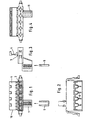
Fig. 1 zeigt einen ersten Steckerbereich 1, in den aus der
Richtung des Betrachters hülsenförmige Steckelemente eingesetzt
sind und einen Steckbereich 2, in den aus der gleichen
Richtung kommend Steckstifte eingesetzt sind. Die Steckstifte
werden durch einen mittels eines Filmscharniers 3 angegossenen
Riegels 4 verriegelt, während die Verriegelung der
Steckhülsen mittels einer Spange 5 geschieht, welche Vorsprünge
der Steckhülsen in ihrem eingesetzten Zustand hintergreift.Fig. 1 shows a first connector portion 1, in which from the
Direction of the viewer sleeve-shaped plug elements used
are and a
In Fig. 2 sind die Enden 6 der Steckstifte zu erkennen, während Fig. 4 Öffnungen zeigt, hinter denen hülsenförmige Steckelemente eingesetzt sind.In Fig. 2, the ends 6 of the plug pins can be seen while Fig. 4 shows openings, behind which sleeve-shaped Plug-in elements are used.
Claims (3)
- Connector comprising an insulated plastic housing (10) and comprising contact elements (6, 11) which can be connected to complementary contact elements of a coordinated second connector, a part of the contact elements (6, 7) being formed by receptacles (11) and the remaining contact elements by pins (6), characterized ina. that the pins (6) and/or the receptacles (11) have dimensions differing from one another andb. that locking means (5, 4) for secure anchoring in the housing (10) are provided for the receptacles (11) and the pins (6), the pins (6) being locked by a bolt (4) while the locking of the receptacles (11) is effected by means of a U-shaped clasp (5) which grips behind projections of the receptacles (11) in their inserted state.
- Connector according to Claim 1, characterized in that the same connecting direction is provided both for the receptacles (11) and for the pins (6).
- Connector according to Claim 1 or 2, characterized in that the receptacles (11) and/or the pins (6) are arranged adjacent to one another in delimited regions (1, 2) of the connector housing (10).
Priority Applications (1)
| Application Number | Priority Date | Filing Date | Title |
|---|---|---|---|
| DE59812928T DE59812928D1 (en) | 1998-03-10 | 1998-03-10 | combination plug |
Applications Claiming Priority (2)
| Application Number | Priority Date | Filing Date | Title |
|---|---|---|---|
| DE19710860A DE19710860A1 (en) | 1997-03-15 | 1997-03-15 | Combination plug |
| DE19710860 | 1997-03-15 |
Publications (3)
| Publication Number | Publication Date |
|---|---|
| EP0865106A2 EP0865106A2 (en) | 1998-09-16 |
| EP0865106A3 EP0865106A3 (en) | 1999-08-04 |
| EP0865106B1 true EP0865106B1 (en) | 2005-07-20 |
Family
ID=7823536
Family Applications (1)
| Application Number | Title | Priority Date | Filing Date |
|---|---|---|---|
| EP98104217A Expired - Lifetime EP0865106B1 (en) | 1997-03-15 | 1998-03-10 | Combination of electrical connectors |
Country Status (2)
| Country | Link |
|---|---|
| EP (1) | EP0865106B1 (en) |
| DE (1) | DE19710860A1 (en) |
Citations (1)
| Publication number | Priority date | Publication date | Assignee | Title |
|---|---|---|---|---|
| US3467942A (en) * | 1965-03-10 | 1969-09-16 | Amp Inc | Housing member |
Family Cites Families (5)
| Publication number | Priority date | Publication date | Assignee | Title |
|---|---|---|---|---|
| US3958849A (en) * | 1974-05-13 | 1976-05-25 | Blairsdale Donald A | Electrical plug |
| US4431249A (en) * | 1982-03-31 | 1984-02-14 | Amp Incorporated | Male/female cable connector |
| JPH03116575U (en) * | 1990-03-07 | 1991-12-03 | ||
| US5582180A (en) * | 1994-11-04 | 1996-12-10 | Physio-Control Corporation | Combination three-twelve lead electrocardiogram cable |
| DE19521726A1 (en) * | 1995-06-14 | 1996-12-19 | Grote & Hartmann | Connector housing |
-
1997
- 1997-03-15 DE DE19710860A patent/DE19710860A1/en not_active Ceased
-
1998
- 1998-03-10 EP EP98104217A patent/EP0865106B1/en not_active Expired - Lifetime
Patent Citations (1)
| Publication number | Priority date | Publication date | Assignee | Title |
|---|---|---|---|---|
| US3467942A (en) * | 1965-03-10 | 1969-09-16 | Amp Inc | Housing member |
Non-Patent Citations (1)
| Title |
|---|
| CADY E.: 'Multimedia Impacts Cabling', 8416 Interconnection Technology, 10, (1994) Februar, No.2, Libertyville, Ill, USA, Seite 10-14 * |
Also Published As
| Publication number | Publication date |
|---|---|
| EP0865106A3 (en) | 1999-08-04 |
| EP0865106A2 (en) | 1998-09-16 |
| DE19710860A1 (en) | 1998-09-24 |
Similar Documents
| Publication | Publication Date | Title |
|---|---|---|
| DE10203162B4 (en) | Interconnects | |
| DE102006003064B4 (en) | Electrical terminal block | |
| DE3320147A1 (en) | RF FILTER CONNECTOR | |
| DE4412968C2 (en) | Electrical junction box | |
| WO2017046370A1 (en) | Power distributor with an electronics system which can be plug-connected | |
| DE3428922C2 (en) | Multipole, detachable plug connection for the transmission of electrical currents, preferably for use on motor vehicles | |
| DE4327282C2 (en) | Device connection terminal | |
| EP0865106B1 (en) | Combination of electrical connectors | |
| DE19840648C1 (en) | Electrical plug-in connector for connecting motor vehicle lighter socket to electrical controller for motor vehicle restraints, e.g. airbags; has plug-in part with locking arms and snap-in lugs to connect to contact springs | |
| DE2915816A1 (en) | Multiple socket accepts either earthed or unearthed plugs - by incorporating second socket for flat plug pin located in space inside socket | |
| DE3641153C2 (en) | ||
| DE3537944C2 (en) | ||
| EP0373498B1 (en) | Plug socket for a multipole plug connection for the electrical link-up of a motor vehicle trailer | |
| DE3923137C1 (en) | Socket for plug-in terminal pins or relay - has tongues for internal wiring accepting further plug-in unit e.g. adaptor | |
| DE19525801A1 (en) | In-line connector for two electrical conductors - has plug-and-socket formed to ensure that ends of cable wires are brought into good contact | |
| DE102012103214B4 (en) | Switching distributor and arrangement of switching distributor and connected switching unit | |
| EP0286697B1 (en) | Disconnectable multipole plug connection for the transfer of electrical currents, for instance for use in motor cars | |
| DE19530335A1 (en) | Plug connection arrangement with two plugs | |
| EP1986281A1 (en) | Method for manufacturing a conducting electrical connection | |
| DE3611661C1 (en) | Electrical connector | |
| DE19618451B4 (en) | Protection against unauthorized loosening for an electrical plug connection | |
| DE19715436C2 (en) | Arrangement with an electrical distribution device | |
| DE10334071B4 (en) | Plug connection system with integrated lock | |
| DE4237753C1 (en) | Rotary switch for vehicle ignition or starter-switch - has flat connections offset from each other in base-plate by distances which allow unhampered cable exit | |
| AT504029B1 (en) | ELECTRICAL MACHINE WITH A CONNECTOR HOUSING MOUNTED TO THE MACHINE BODY |
Legal Events
| Date | Code | Title | Description |
|---|---|---|---|
| PUAI | Public reference made under article 153(3) epc to a published international application that has entered the european phase |
Free format text: ORIGINAL CODE: 0009012 |
|
| AK | Designated contracting states |
Kind code of ref document: A2 Designated state(s): DE FR GB |
|
| AX | Request for extension of the european patent |
Free format text: AL;LT;LV;MK;RO;SI |
|
| PUAL | Search report despatched |
Free format text: ORIGINAL CODE: 0009013 |
|
| AK | Designated contracting states |
Kind code of ref document: A3 Designated state(s): AT BE CH DE DK ES FI FR GB GR IE IT LI LU MC NL PT SE |
|
| AX | Request for extension of the european patent |
Free format text: AL;LT;LV;MK;RO;SI |
|
| RIC1 | Information provided on ipc code assigned before grant |
Free format text: 6H 01R 13/514 A, 6H 01R 27/02 B |
|
| 17P | Request for examination filed |
Effective date: 19990927 |
|
| AKX | Designation fees paid |
Free format text: DE FR GB |
|
| 17Q | First examination report despatched |
Effective date: 20000419 |
|
| RAP1 | Party data changed (applicant data changed or rights of an application transferred) |
Owner name: VALEO SCHALTER UND SENSOREN GMBH |
|
| GRAP | Despatch of communication of intention to grant a patent |
Free format text: ORIGINAL CODE: EPIDOSNIGR1 |
|
| RIC1 | Information provided on ipc code assigned before grant |
Ipc: 7H 01R 13/436 B Ipc: 7H 01R 27/02 B Ipc: 7H 01R 13/514 A |
|
| GRAS | Grant fee paid |
Free format text: ORIGINAL CODE: EPIDOSNIGR3 |
|
| GRAA | (expected) grant |
Free format text: ORIGINAL CODE: 0009210 |
|
| AK | Designated contracting states |
Kind code of ref document: B1 Designated state(s): DE FR GB |
|
| REG | Reference to a national code |
Ref country code: GB Ref legal event code: FG4D Free format text: NOT ENGLISH |
|
| REF | Corresponds to: |
Ref document number: 59812928 Country of ref document: DE Date of ref document: 20050825 Kind code of ref document: P |
|
| GBT | Gb: translation of ep patent filed (gb section 77(6)(a)/1977) |
Effective date: 20050808 |
|
| ET | Fr: translation filed | ||
| PLBE | No opposition filed within time limit |
Free format text: ORIGINAL CODE: 0009261 |
|
| STAA | Information on the status of an ep patent application or granted ep patent |
Free format text: STATUS: NO OPPOSITION FILED WITHIN TIME LIMIT |
|
| 26N | No opposition filed |
Effective date: 20060421 |
|
| PGFP | Annual fee paid to national office [announced via postgrant information from national office to epo] |
Ref country code: GB Payment date: 20080307 Year of fee payment: 11 |
|
| PGFP | Annual fee paid to national office [announced via postgrant information from national office to epo] |
Ref country code: DE Payment date: 20080311 Year of fee payment: 11 |
|
| PGFP | Annual fee paid to national office [announced via postgrant information from national office to epo] |
Ref country code: FR Payment date: 20080401 Year of fee payment: 11 |
|
| GBPC | Gb: european patent ceased through non-payment of renewal fee |
Effective date: 20090310 |
|
| REG | Reference to a national code |
Ref country code: FR Ref legal event code: ST Effective date: 20091130 |
|
| PG25 | Lapsed in a contracting state [announced via postgrant information from national office to epo] |
Ref country code: DE Free format text: LAPSE BECAUSE OF NON-PAYMENT OF DUE FEES Effective date: 20091001 |
|
| PG25 | Lapsed in a contracting state [announced via postgrant information from national office to epo] |
Ref country code: GB Free format text: LAPSE BECAUSE OF NON-PAYMENT OF DUE FEES Effective date: 20090310 Ref country code: FR Free format text: LAPSE BECAUSE OF NON-PAYMENT OF DUE FEES Effective date: 20091123 |