EP0866453A2 - Magnetic reproduction apparatus having MR head - Google Patents
Magnetic reproduction apparatus having MR head Download PDFInfo
- Publication number
- EP0866453A2 EP0866453A2 EP97122986A EP97122986A EP0866453A2 EP 0866453 A2 EP0866453 A2 EP 0866453A2 EP 97122986 A EP97122986 A EP 97122986A EP 97122986 A EP97122986 A EP 97122986A EP 0866453 A2 EP0866453 A2 EP 0866453A2
- Authority
- EP
- European Patent Office
- Prior art keywords
- head
- sense current
- information
- servo information
- current
- Prior art date
- Legal status (The legal status is an assumption and is not a legal conclusion. Google has not performed a legal analysis and makes no representation as to the accuracy of the status listed.)
- Granted
Links
Images


Classifications
-
- G—PHYSICS
- G11—INFORMATION STORAGE
- G11B—INFORMATION STORAGE BASED ON RELATIVE MOVEMENT BETWEEN RECORD CARRIER AND TRANSDUCER
- G11B19/00—Driving, starting, stopping record carriers not specifically of filamentary or web form, or of supports therefor; Control thereof; Control of operating function ; Driving both disc and head
- G11B19/02—Control of operating function, e.g. switching from recording to reproducing
- G11B19/04—Arrangements for preventing, inhibiting, or warning against double recording on the same blank or against other recording or reproducing malfunctions
-
- G—PHYSICS
- G11—INFORMATION STORAGE
- G11B—INFORMATION STORAGE BASED ON RELATIVE MOVEMENT BETWEEN RECORD CARRIER AND TRANSDUCER
- G11B5/00—Recording by magnetisation or demagnetisation of a record carrier; Reproducing by magnetic means; Record carriers therefor
-
- G—PHYSICS
- G11—INFORMATION STORAGE
- G11B—INFORMATION STORAGE BASED ON RELATIVE MOVEMENT BETWEEN RECORD CARRIER AND TRANSDUCER
- G11B5/00—Recording by magnetisation or demagnetisation of a record carrier; Reproducing by magnetic means; Record carriers therefor
- G11B5/012—Recording on, or reproducing or erasing from, magnetic disks
-
- G—PHYSICS
- G11—INFORMATION STORAGE
- G11B—INFORMATION STORAGE BASED ON RELATIVE MOVEMENT BETWEEN RECORD CARRIER AND TRANSDUCER
- G11B5/00—Recording by magnetisation or demagnetisation of a record carrier; Reproducing by magnetic means; Record carriers therefor
- G11B5/48—Disposition or mounting of heads or head supports relative to record carriers ; arrangements of heads, e.g. for scanning the record carrier to increase the relative speed
- G11B5/54—Disposition or mounting of heads or head supports relative to record carriers ; arrangements of heads, e.g. for scanning the record carrier to increase the relative speed with provision for moving the head into or out of its operative position or across tracks
- G11B5/55—Track change, selection or acquisition by displacement of the head
- G11B5/5521—Track change, selection or acquisition by displacement of the head across disk tracks
- G11B5/5526—Control therefor; circuits, track configurations or relative disposition of servo-information transducers and servo-information tracks for control thereof
-
- G—PHYSICS
- G11—INFORMATION STORAGE
- G11B—INFORMATION STORAGE BASED ON RELATIVE MOVEMENT BETWEEN RECORD CARRIER AND TRANSDUCER
- G11B5/00—Recording by magnetisation or demagnetisation of a record carrier; Reproducing by magnetic means; Record carriers therefor
- G11B5/48—Disposition or mounting of heads or head supports relative to record carriers ; arrangements of heads, e.g. for scanning the record carrier to increase the relative speed
- G11B5/58—Disposition or mounting of heads or head supports relative to record carriers ; arrangements of heads, e.g. for scanning the record carrier to increase the relative speed with provision for moving the head for the purpose of maintaining alignment of the head relative to the record carrier during transducing operation, e.g. to compensate for surface irregularities of the latter or for track following
- G11B5/596—Disposition or mounting of heads or head supports relative to record carriers ; arrangements of heads, e.g. for scanning the record carrier to increase the relative speed with provision for moving the head for the purpose of maintaining alignment of the head relative to the record carrier during transducing operation, e.g. to compensate for surface irregularities of the latter or for track following for track following on disks
- G11B5/59683—Disposition or mounting of heads or head supports relative to record carriers ; arrangements of heads, e.g. for scanning the record carrier to increase the relative speed with provision for moving the head for the purpose of maintaining alignment of the head relative to the record carrier during transducing operation, e.g. to compensate for surface irregularities of the latter or for track following for track following on disks for magnetoresistive heads
-
- G—PHYSICS
- G11—INFORMATION STORAGE
- G11B—INFORMATION STORAGE BASED ON RELATIVE MOVEMENT BETWEEN RECORD CARRIER AND TRANSDUCER
- G11B5/00—Recording by magnetisation or demagnetisation of a record carrier; Reproducing by magnetic means; Record carriers therefor
- G11B2005/0002—Special dispositions or recording techniques
- G11B2005/0005—Arrangements, methods or circuits
- G11B2005/001—Controlling recording characteristics of record carriers or transducing characteristics of transducers by means not being part of their structure
- G11B2005/0013—Controlling recording characteristics of record carriers or transducing characteristics of transducers by means not being part of their structure of transducers, e.g. linearisation, equalisation
- G11B2005/0016—Controlling recording characteristics of record carriers or transducing characteristics of transducers by means not being part of their structure of transducers, e.g. linearisation, equalisation of magnetoresistive transducers
Definitions
- the present invention relates to a magnetic reproduction apparatus having a magnetoresistance effect head (MR head). More particularly, this invention is concerned with a magnetic reproduction apparatus in which electromigration occurring in an MR head for reproducing information recorded on a magnetic recording medium is suppressed.
- MR head magnetoresistance effect head
- a magnetic recording/reproducing apparatus for recording or reproducing information on or from a magnetic recording medium, such as a magnetic disk unit or magnetic tape unit
- a magnetic recording/reproducing apparatus having a composite head composed of a winding-type thin film magnetic head (inductive head) used for recording on a recording medium and an MR head used for reproduction has been put to practical use.
- An MR head included in such a composite head detects a leakage magnetic field induced by a reversal of magnetization in a recording medium on the basis of the fact that the resistance of an element varies depending on an external magnetic field.
- a current termed a sense current is fed to the element when it is used.
- a reproduced output of the MR head is, unlike that of an inductive head, independent of the speed of the head in relation to a recording medium, is acquired as a relatively large value proportional to a magnetic flux density, and is therefore very useful in reproducing data from a high-density recording track.
- the sense current flowing into the element in the MR head is increased, a large reproduced signal can be acquired irrespective of the relative speed of the head in relation to a disk. For this reason, the MR head is favorably adopted for a high-density magnetic disk unit. Due to an increasing demand for a larger-capacity magnetic disk units to be used as external storage units for computers, the MR head has been widely adopted in recent years.
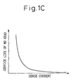
- the service life of an MR head is inversely proportional to the value of a sense current.
- the service life of the MR head is inversely proportional to the time during which the MR head conducts the sense current.
- a sense current flowing into the MR head is usually set to the range from 10 6 to 10 7 A/cm 2 in an effort to acquire a large reproduced output from the MR head.
- an element in the MR head is heated to a higher temperature than that in an inductive head.
- the current density of the sense current is high, the electromigration phenomenon takes place. This brings about the fear of deterioration of the magnetic properties of a magnetic film in a head or the fear of a disconnection.
- a countermeasure against electromigration implemented in a known magnetic disk unit is, for example, as disclosed in Japanese Unexamined Patent Publication No. 5-225531, to reverse the sense current.
- the first object of the present invention is to solve the problems lying in the prior art and to provide a magnetic reproduction apparatus having a highly durable and reliable MR head in which an adverse effect of electromigration on the MR head is prevented by including a control means for giving control so that a sense current will not flow into the MR head during a period during which it is unnecessary to supply the sense current to the MR head.
- the second object of the present invention is to provide a magnetic disk unit having a highly reliable and durable MR head in which the direction of a sense current is reversed only during a period during which it is unnecessary to supply the sense current to the MR head.
- the third object of the present invention is to improve the reliability and durability of a sector-servo type magnetic disk unit having a plurality of MR heads by adopting an MR head, which has the smallest total flowing time of a sense current, for a seeking operation or track tracing operation and by thus making the service lives of the MR heads uniform.
- a magnetic reproduction apparatus having an MR head
- information magnetically recorded on at least one recording medium is read by supplying a sense current to an MR head opposed to a record surface of the recording medium using a current supply means, and then decoded by a signal decoding means.
- the magnetic reproduction apparatus comprises an MR head information judgment means for judging whether or not information to be read from the recording medium by the MR head is needed, and a current supply control means that when information to be read out by the MR head is needed, allows the current supply means to supply the sense current to the MR head.
- the current supply control means judges that information to be read out by the MR head is not needed, the current supply control means turns off the on-off operation means.
- the current supply control means judges that information to be read out by the MR head is needed.
- the recording medium is a magnetic disk.
- a servo information thinning and sampling means for sampling and reading every M-th servo information item by thinning N servo information items residing along one circumference of the disk, a servo information predicting means for predicting current servo information as a substitute for thinned-out servo information on the basis of such information as a previous rotating speed of the disk, the position of the MR head, an output current, and a bias current, and a position control means for controlling the position of the MR head on the basis of the predicted servo information may be included.
- a control parameter storage means for storing parameters for position control specified for thinning and sampling which are different from parameters for position control specified for normal position control may be substituted for the servo information prediction means.
- the position control means may use the different position control parameters to control the position of the MR head.
- the sense current flowing into an MR head during seeking or track tracing is limited.
- the ratio of the time for seeking and track tracing to a total operation time of the magnetic reproduction apparatus is the largest. Electromigration can therefore be suppressed effectively, and the durability and reliability of the magnetic reproduction apparatus is improved.
- the magnetic reproduction apparatus having an MR head further comprises a reproduction detection means for detecting that the magnetic reproduction apparatus is engaged in reproduction, and a polarity reversal means for supplying the sense current to the MR head while reversing the polarity of the sense current according to a predetermined timing when the magnetic reproduction apparatus is not engaged in reproduction.
- the polarity reversal means reverses the direction of the sense current flowing into the MR head. This makes it unnecessary to take care of a variation in reproduction ability of the MR head derived from a variation in polarity of the sense current, that is, the positive or negative polarity thereof. Moreover, since an integrated value of the sense current calculated by taking account of the signs of the levels is stored all the time. The direction of the sense current can be reversed according to the timing of making the integrated value null. As a result, electromigration is suppressed. Thus, a highly durable and reliable magnetic reproduction apparatus is provided.
- the predetermined timing is found within a period during which information to be read from the recording medium by the MR head is judged not to be needed by the MR head information judging means.
- an integration means for calculating the time during which each MR head conducts a sense current
- a shortest operation MR head identification means for identifying an MR head that has conducted the sense current for the shortest time or the sense current of the smallest integrated value
- a servo current selection and supply means that when servo information is to be read out by an MR head, reads out servo information by supplying the sense current to an MR head having conducted the sense current for the shortest time or the sense current of the smallest integrated value are included.
- the servo current selection and supply means may supply the sense current successively to the MR heads over the same time per head.
- the MR head information judgment means may judge whether or not information to be read out by an MR head is needed by recognizing which of a Read gate signal or Servo gate signal is produced by the current supply control means.
- an MR head to which a sense current is supplied is switched to another at certain intervals so that the total time during which the sense current is supplied will be equal among the heads. Consequently, it will not take place that electromigration occurring in a certain head progresses. Eventually, the durability and reliability of the magnetic reproduction apparatus improve.
- Fig. 1C is a graph showing the relationship between the magnitude of a sense current to be supplied to an MR head and the service life of the MR head. As seen from Fig. 1C, the service life of an MR head is inversely proportional to the level of the sense current. When a certain sense current is supplied to an MR head, the service life of the MR head is inversely proportional to the time during which the MR head conducts the sense current.
- a sense current to be supplied to an MR head is increased in order to obtain a large reproduced output from the MR head, the service life of the MR head is shortened.
- a magnetoresistor is heated to a high temperature.
- an electromigration phenomenon takes place. This brings about deterioration in magnetic property of a magnetic film of the head or disconnection. Consequently, the service life of the MR head is shortened.
- the present invention attempts to extend the service life of an MR head while suppressing electromigration.
- Fig. 1A shows the configuration of a magnetic reproduction apparatus 10 having an MR head in accordance with the first embodiment which is based on the principle of the present invention and intended to accomplish the first object of the present invention.
- the magnetic reproduction apparatus 10 has an on-off operation means 7A interposed between an MR head 2 and current supply means 3.
- a sense current is supplied from the current supply means 3 to the MR head 2 opposed to a record surface of at least one recording medium 1.
- information magnetically recorded on the recording medium 1 is read by the MR head 2.
- Information read by the MR head 2 is then decoded by a signal decoding means 4. Whether or not the decoded information is needed is judged by an MR head information judgment means 5. If information read by the MR head 2 is needed, a current supply control means 6 allows the current supply means 3 to supply a sense current to the MR head 2.
- the on-off operation means 7A is turned off.
- Fig. 1B shows the configuration of a magnetic reproduction apparatus 20 having an MR head in accordance with the second embodiment which is based on the principle of the present invention and intended to accomplish the first object of the present invention.
- the magnetic reproduction apparatus 20 has an on-off operation means 7B interposed between a current supply means 3 and power supply 8.
- a sense current is supplied from a current supply means 3 to an MR head 2 opposed to a record surface of at least one recording medium 1.
- information magnetically recorded on the recording medium 1 is read by the MR head 2.
- the information read by the MR head 2 is decoded by a signal decoding means 4. Whether or not the decoded information is needed is judged by an MR head information judgment means 5. If information read by the MR head 2 is needed, a current supply control means 6 allows the current supply means 3 to supply a sense current to the MR head 2.
- the on-off operation means 7B is turned off.
- the magnetic reproduction apparatuses 10 and 20 only when it is necessary to read out information from the recording medium 1 using the MR head 2, is a sense current supplied to the MR head 2.
- the time during which the MR head 2 conducts the sense current can be shortened. This leads to suppression of electromigration.
- the durability and reliability of the magnetic reproduction apparatuses 10 and 20 improve.
- the recording medium 1 is a magnetic disk.
- a servo information thinning and sampling means for sampling and reading every M-th servo information item by thinning N servo information items residing along one circumference of the disk, a servo information prediction means for predicting current servo information as a substitute for thinned-out servo information on the basis of such information as a previous rotating speed of the disk 1, the position of the MR head 2, an output current, and a bias current, and a position control means for controlling the position of the MR head 2 on the basis of the predicted servo information are further included.
- a control parameter storage means for storing parameters for position control specified for thinning and sampling which are difference from parameters for position control specified for normal position control may be substituted for the servo information prediction means.
- the position control means may control the position of the MR head 2 using the different position control parameters.
- the sense current to be supplied to the MR head is limited. Consequently, electromigration is suppressed effectively, and the durability and reliability of the magnetic reproduction apparatus improve.
- the magnetic reproduction apparatus 10 or 20 shown in Fig. 1A or 1B further comprises a reproduction detection means for detecting whether or not the magnetic reproduction apparatus is engaged in reproduction, and a polarity reversal means for supplying a sense current to the MR head while reversing the polarity of the sense current according to given timing when the magnetic reproduction apparatus is not engaged in reproduction.
- the predetermined timing is set within a period during which information to be read out from the recording medium 1 by the MR head 2 is judged not to be needed by the MR head information judgment means 5.
- the direction of a sense current to be supplied to the MR head 2 is reversed.
- a variation in reproduction ability of the MR head 2 derived from a reversal in polarity of a sense current, that is, the positive or negative polarity thereof need not be considered.
- the direction of the sense current can be reversed according to the timing of making the integrated value zero. As a result, electromigration is suppressed, and the durability and reliability of the magnetic reproduction apparatuses 10 and 20 improve.
- the magnetic reproduction apparatus 10 or 20 shown in Fig. 1A or 1B includes a plurality of MR heads 2, and further comprises an integration means for calculating the time during which each MR head 2 conducts a sense current, a shortest operation MR head identification means for identifying an MR head 2 that has conducted the sense current for the shortest time, and a servo current selection and supply means that when servo information is to be read out by an MR head 2, reads servo information by supplying the sense current to the MR head whose total flowing time of the sense current for the shortest time is the smallest.
- an MR head to which a sense current is supplied is switched to another at certain intervals so that the total time during which the sense current is supplied to a head will be equal among the MR heads. It will therefore not take place that electromigration occurring in a certain head progresses.
- the durability and reliability of the magnetic reproduction apparatus improve.
- the servo current selection and supply means may read servo information by supplying a sense current successively to the MR heads over the same time per head.
- the MR head information judgment means may judge whether or not information to be read out by an MR head is needed by recognizing which of a Read gate signal or Servo gate signal is produced by the current supply control means.
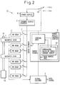
- Fig. 2 shows the configuration of a magnetic reproduction apparatus 11 of the first embodiment of the present invention corresponding to the configuration shown in Fig. 1A based on the principle of the present invention.
- the magnetic reproduction apparatus 11 is a magnetic disk unit having MR heads 2.
- magnetic disks 1 corresponding to at least one recording medium are attached to the same rotational shaft 1A of a spindle motor 1B.
- the rotational shaft 1A is driven to rotate by means of a spindle motor 1B.
- MR heads 2 for reading information magnetically recorded on the magnetic disks 1 are located at regions opposed to the record surfaces of the magnetic disks 1.
- a sense current is supplied from a current supply circuit 3 to the MR heads 2.
- Information read out from the magnetic disks 1 by the MR heads 2 is decoded by a signal decoder 4.
- the signal decoder 4 outputs a decoded data signal and servo signal.
- the data signal is input to a data processing circuit that is not shown, and the servo signal is input to a control unit 61 in a power supply control circuit 6.
- the power supply control circuit 6 controls supply of a sense current from the current supply circuit 3 to the MR heads 2, and includes a main memory unit 63 having an integrated value-of-sense current memory 62 in addition to the control unit 61.
- On-off switches 71 are located on a path along which a sense current is supplied from the current supply circuit 3 to the MR heads 2, and connected in series with the respective MR heads.
- the control unit 61 in the power supply control circuit 6 turns on any of the on-off switches 71 so as to supply a sense current from the current supply circuit 3 to a desired MR head 2.
- the current supply circuit 3 is connected to a power supply 8.
- the power supply 8 is connected to a positive voltage source +Vcc and negative voltage source -Vcc, which are mutually opposite in polarity, via a selection switch 81.
- the selection switch 81 is normally connected to the positive voltage source +Vcc.
- an on-off switch 71 When an on-off switch 71 is turned on, a sense current of positive polarity is supplied to an associated MR head.
- the selection switch 81 is connected to the negative voltage source -Vcc, a sense current of negative polarity is supplied from the power supply 8 through the current supply circuit 3 and on-off switch 71.
- a sense current supplied to an individual MR head 2 is controllable.
- Fig. 3 shows the configuration of a magnetic reproduction apparatus 21 in accordance with the second embodiment of the present invention which corresponds to the configuration shown in Fig. 1B which is based on the principle of the present invention.
- the magnetic reproduction apparatus 11 is a magnetic disk unit having MR heads 2.
- the configuration of the magnetic reproduction apparatus 21 in accordance with the second embodiment is identical to that of the magnetic reproduction apparatus 11 in accordance with the first embodiment except a position at which an on-off switch 72 is installed.
- the on-off switches 71 in the magnetic reproduction apparatus 11 of the first embodiment are connected in series with all the MR heads 2 and placed between the MR heads and the current supply circuit 3.
- the on-off switch 72 in the magnetic reproduction apparatus 21 of the second embodiment is interposed between the current supply circuit 3 and power supply 8. This is the only difference from the first embodiment.
- the other components of the magnetic reproduction apparatus 21 of the second embodiment are identical to those of the magnetic reproduction apparatus 11 of the first embodiment. A description of the components will therefore be omitted.
- the control unit 61 shown in Figs. 2 and 3 includes, as shown in Fig. 4, an MPU 612 for outputting a Write gate signal, Servo gate signal, and Read gate signal which will be described later, and a head controller 611.
- FIG. 5 shows an example of a format for one track in a sector-servo type magnetic disk apparatus.
- N servo frames are defined along one circumference of each track on a magnetic disk.
- Each frame shall have a servo information division SV in which servo information is recorded and a data division DATA in which data is recorded.
- SV servo information division
- DATA data division DATA
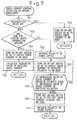
- Fig. 6 describes a control flow for a sense current control operation in accordance with the first embodiment of the present invention.
- the control flow shall be implemented in, for example, the magnetic reproduction apparatus of the first embodiment of the present invention described with reference to Fig. 2.
- step 601 it is judged whether or not the magnetic disk unit 11 is engaged in reproduction. If the magnetic disk unit 11 is engaged in reproduction, reproduction of data by an MR head 2 must be carried out. Control is therefore passed to step 602. An associated on-off switch 71 is turned on so that a sense current will flow into the MR head 2. This routine is then terminated.
- step 601 If it is judged at step 601 that the magnetic disk unit 11 is not engaged in reproduction, control is passed to step 603. If it is judged that the magnetic disk unit 11 is not engaged in reproduction, recording, seeking, or track tracing is under way. In this case, it is necessary to read servo information by an MR head 2. At step 603, therefore, it is judged whether or not the timing of reading servo information has come.
- step 603 If it is judged at step 603 that the timing of reading servo information has come, control is passed to step 604. An associated on-off switch 71 is turned on so that a sense current will flow into the MR head 2. The routine is then terminated. If it is judged at step 603 that the timing of reading servo information has not come, it means that the MR head 2 lies in a data division in which a sense current need not be supplied. Control is therefore passed to step 605. The on-off switch 71 is turned off in order to cut off the sense current flowing into the MR head 2. The routine is then terminated.
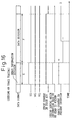
- Figs. 11 to 13 are timing charts showing the relationships between gate signals to be applied for recording, reproduction, and seeking or track tracing respectively and a sense current controlled according to the control flow of the first embodiment described in Fig. 6 with respect to the data format for the sector-servo type magnetic disk apparatus 11.
- a Servo gate signal SG representing servo information
- a Write gate signal WG instructing writing in a data division
- a Read gate signal RG instructing read from a data division.
- a period during which information read by an MR head 2 is needed includes periods during which the MR head passes through a servo information division C and data division D for reproduction, and periods during which the MR head passes through servo information areas A and E for recording, seeking, and track tracing. During periods during which an MR head passes through data divisions B and F for recording, seeking, and track tracing, information read by the MR head 2 is not needed.
- the sense current control operation in the first embodiment of the present invention which has been described in Fig. 6, as shown in Fig. 12, when reproduction is under way, while an MR head 2 passes through the servo information division C and data division D, a sense current is supplied to the MR head 2.
- a sense current is not supplied.
- the above control operation of controlling supply of a sense current is executed according to the control flow described in Fig. 6, wherein the power supply control circuit 2 controls the on-off operation of an on-off switch 71. Specifically, when recording, seeking, or track tracing is under way, the supply control circuit 6 turns off an on-off switch 71 so as to cut off a sense current responsively to the start of a Write gate signal WG indicating a data division or the end of a Servo gate signal SG representing servo information, or using an equivalent signal as a trigger.
- the supply control circuit 6 turns on an on-off switch 71 so as to supply a sense current in responsive to the end of the Write gate signal WG indicating a data division or the start of the Servo gate signal SG representing servo information, or using an equivalent signal as a trigger.
- an MR head 2 since an MR head 2 does not conduct a sense current while it passes through the data division D or F during recording, seeking, or track tracing during which information read by the MR head 2 is not needed, electromigration can be suppressed.
- Fig. 7 describes a control flow for a sense current control operation in accordance with the second embodiment of the present invention. The description will proceed on the assumption that the control flow is implemented in the magnetic reproduction apparatus of the first embodiment described with reference to Fig. 2.
- step 701 it is judged whether or not the magnetic disk unit 11 is engaged in reproduction. If the magnetic disk unit 11 is engaged in reproduction, reproduction of data by an MR head 2 should be carried out. Control is therefore passed to step 702. An associated on-off switch 71 is turned on so that a sense current will flow into the MR head 2. The routine is then terminated.
- step 701 if it is judged at step 701 that the magnetic disk unit 11 is not engaged in reproduction, recording, seeking, or track tracing is under way. Control is therefore passed to step 703.
- step 703 it is judged whether or not the timing of reading servo information has come. If it is judged at step 703 that the timing of reading servo information has come, control is passed to step 704.
- the on-off switch 71 is turned on so that a sense current will flow into the MR head 2.
- step 705 an integrated value of the supplied sense current is calculated by integrating the levels of the sense current. The routine is then terminated.
- step 703 If it is found at step 703 that the timing of reading servo information has not come, the MR head 2 lies in a data division in which it is unnecessary to supply a sense current. Control is therefore passed to step 706. A destination to which the selection switch 81 is connected is changed from the positive voltage source +Vcc to the negative voltage source -Vcc, whereby an output voltage is reversed. At step 707, the on-off switch 71 is turned on so that a sense current of opposite polarity will flow into the MR head 2.
- step 708 it is judged whether or not the level of the sense current of opposite polarity to be supplied to the MR head 2 becomes equal to the integrated value of the sense current of positive polarity calculated at step 705. If they are unequal, control is returned to step 707.
- the integrated value of the sense current of opposite polarity to be supplied to the MR head becomes equal to the integrated value of the sense current supplied to the MR head 2
- control is passed to step 709.
- the on-off switch 71 is then turned off, thus cutting off the sense current flowing into the MR head.
- step 710 the destination to which the selection switch 81 is connected is changed from the negative voltage source -Vcc to the positive voltage source +Vcc. The output voltage of the power supply 8 is thus changed again, and then the routine is terminated.
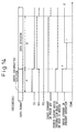
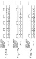
- Figs. 14 to 16 are timing charts showing the relationships between gate signals to be applied for recording, reproduction, and seeking or track tracing respectively and a sense current controlled according to the control flow described in Fig. 7 in the second embodiment with respect to the data format for the sector-servo type magnetic disk unit 21.
- Figs. 14 to 16 there are shown a Servo gate signal SG representing servo information, a Write gate signal WG indicating writing in a data division, and a Read gate signal RG indicating read from a data division. Except a sense current in accordance with the present invention, the signals shown in Figs. 14 to 16 have the same characteristics as those shown in Figs. 11 to 13.
- a sense current whose polarity is opposite to the polarity of the sense current supplied while the MR head passes through the servo information division A or E is supplied over a period corresponding to the time required for the MR head to pass through the servo information division A or E.
- the control operation for controlling supply of a sense current can be executed according to the control flow described in Fig. 7, wherein the power supply control circuit 6 shown in Fig. 2 controls the on-off operation of an on-off switch 71, and changes the destination to which the selection switch is connected from one to the other.
- the power supply control circuit 6 shown in Fig. 2 controls the on-off operation of an on-off switch 71, and changes the destination to which the selection switch is connected from one to the other.
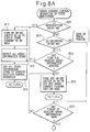
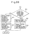
- Fig. 8 shows a control flow for a sense current control operation in accordance with the third embodiment of the present invention. The description will proceed on the assumption that the control flow is implemented in, for example, the magnetic reproduction apparatus in accordance with the first embodiment of the present invention which has been described in conjunction with Fig. 2.
- step 801 it is judged whether or not the magnetic disk unit 11 is engaged in reproduction. If the magnetic disk unit 11 is engaged in reproduction, reproduction of data by an MR head 2 should be carried out. Control is therefore passed to step 811. An associated on-off switch 71 is turned on so that a sense current will flow into the MR head 2. At step 812, all servo information items read by the MR head 2 are detected. At step 813, all the detected servo information items are used to execute a position control operation for the MR head 2.
- step 801 if it is judged at step 801 that the magnetic disk unit 11 is not engaged in reproduction, control is passed to step 802. It is then judged whether or not the magnetic disk unit is engaged in recording. If the magnetic disk unit 1 is engaged in recording, control is passed to step 809. It is then judged whether or not the timing of reading servo information has come. When the timing of reading servo information has come, control is passed to step 811. The processing from step 811 to step 813 is carried out. If it is judged at step 809 that the timing of reading servo information has not come, control is passed to step 810. The on-off switch 71 is turned off in order to cut off the sense current flowing into the MR head 2. The routine is then terminated.
- step 802 if it is judged at step 802 that the magnetic disk unit is engaged in seeking or track tracing, control is passed to step 803. At step 803, it is judged whether or not the timing of reading servo information has come. If it is judged at step 803 that the timing of reading servo information has not come, the on-off switch 71 is turned off in order to cut off the sense current flowing into the MR head 2. The routine is then terminated.
- step 803 If it is judged at step 803 that the timing of reading servo information has come, control is passed to step 804. It is then judged whether or not the timing of reading servo information is the timing of reading every M-th servo information item. If it is judged at step 804 that the timing of reading servo information is the timing of reading every M-th servo information item, control is passed to step 805. Servo information is then read and stored. At step 806, the read servo information is used to execute a position control operation for the MR head 2. The routine is then terminated.
- step 804 determines whether the timing of reading servo information is not the timing of reading every M-th servo information item. If it is judged at step 804 that the timing of reading servo information is not the timing of reading every M-th servo information item, control is passed to step 807. At step 807, thinned-out servo information is predicted on the basis of previous servo information. At step 808, the predicted servo information is used to execute a position control operation for the MR head 2. The routine is then terminated.
- a sense current is supplied to the MR head 2.
- Fig. 17b for example, every other servo information division SV is read out by an MR head 2, and a servo information division SV next to every other servo information division SV is not read out. In other words, every second servo information division SV is read out.
- every M-th servo information item is read.
- thinned-out servo information is predicted on the basis of previous servo information. Based on the predicted servo information, the position of an MR head 2 is controlled.
- the integrated value of a sense current flowing into an MR head 2 gets smaller than it is when all servo information divisions are read out during seeking or track tracing. Electromigration in the MR head 2 can therefore be suppressed.
- Fig. 9 describes a control flow for a sense current control operation in accordance with the fourth embodiment of the present invention. The description will proceed on the assumption that the control flow is implemented in the magnetic reproduction apparatus in accordance with the first embodiment of the present invention which has been described in conjunction with Fig. 2.
- the control flow for a sense current control operation in accordance with the fourth embodiment which is described in Fig. 9 is substantially identical to the control flow for a sense current control operation in accordance with the third embodiment which has been described in Fig. 8.
- a difference lies in a control operation to be carried out when the disk unit 11 is engaged in seeking or track tracing and it is found at step 804 that the timing is not the timing of reading every M-th servo information item.
- the same step numbers are assigned to the steps in the control flow described in Fig. 9 identical to the steps in the control flow described in Fig. 8. The description of the steps will be omitted.
- the integrated value of a sense current flowing into an MR head gets smaller than it is when servo information is read out from all servo information divisions during seeking or track tracing. Electromigration in an MR head 2 can therefore be suppressed.
- the control flows for a sense current control operation to be carried out in the magnetic disk unit 11 shown in Fig. 2 in accordance with the first to fourth embodiments of the present invention have been described so far.
- the control flows may be implemented in the magnetic disk unit 21 shown in Fig. 4. In this case, when it is unnecessary to supply a sense current to an MR head 2, the path between the current supply circuit 3 and power supply 8 is disconnected. An excess power consumption in the current supply circuit 3 can be minimized.
- Fig. 10 describes a control flow for a sense current control operation in accordance with the fifth embodiment of the present invention.
- the control flow can be implemented in the magnetic reproduction apparatus in accordance with the first embodiment of the present invention which has been described in conjunction with Fig. 2, that is, the configuration capable of controlling supply of a sense current to each MR head 2.
- the number of MR heads 2 included in the apparatus shown in Fig. 2 shall be three, or heads #1, #2, and #3 shall be included.
- step 1001 it is judged whether or not the magnetic disk unit 11 is engaged in reproduction. If the magnetic disk unit 11 is engaged in reproduction, reproduction of data by an MR head 2 should be carried out. Control is therefore passed to step 1011. An associated on-off switch 71 is turned on so that a sense current will flow into an MR head 2 specified with a previous command. At step 1012, all servo information items read by the MR head 2 are detected. At step 1013, all the detected servo information items are used to execute a position control operation for the MR head 2. Thereafter, at step 1014, the levels of a sense current supplied to the MR head are integrated. The routine is then terminated. The integrated value of the sense current is stored in the integrated value-of-sense current memory 63 shown in Fig. 2.
- step 1001 If it is judged at step 1001 that the magnetic disk unit 11 is not engaged in reproduction, control is passed to step 1002. It is then judged whether or not the magnetic disk unit is engaged in recording. If the magnetic disk unit 11 is engaged in recording, control is passed to step 1009. It is then judged whether or not the timing of reading servo information has come. When the timing of reading servo information has come, control is passed to step 1011. The processing from step 1011 to step 1014 is then carried out. If it is judged at step 1009 that the timing of reading servo information has not come, control is passed to step 1010. The on-off switch 71 is turned off in order to cut off the sense current flowing into the MR head 2. The routine is then terminated.
- step 1002 if it is judged at step 1002 that the magnetic disk unit is engaged in seeking or track tracing, control is passed to step 1003.
- step 1003 it is judged whether or not the timing of reading servo information has come. If it is judged at step 1003 that the timing of reading servo information has not come, control is passed to step 1010.
- the on-off switch 71 is then turned off in order to cut off the sense current flowing into the MR head 2. The routine is then terminated.
- step 1034 If it is judged at step 1003 that the timing of reading servo information has come, control is passed to step 1004. It is then judged whether or not the integrated value of a sense current flowing into head #1 is the smallest. If the integrated value of the sense current flowing into head #1 is the smallest, control is passed to step 1005. An on-off switch 71 connected in series with head #1 is turned on so that a sense current will flow into head #1. Servo information is then read out. After the servo information is read out by head #1, control is passed to step 1012. The processing from step 1012 to step 1014 is then carried out.
- step 1004 determines whether or not the integrated value of the sense current flowing into head #1 is not the smallest. If it is judged at step 1004 that the integrated value of the sense current flowing into head #1 is not the smallest, control is passed to step 1006. It is then judged whether or not the integrated value of a sense current flowing into head #2 is the smallest. If the integrated value of the sense current flowing into head #2 is the smallest, control is passed to step 1007. An on-off switch 71 connected in series with head #2 is turned on so that a sense current will flow into head #2. Servo information is then read out. After the servo information is read out by head #2, control is passed to step 1012. The processing from step 1012 to step 1014 is then carried out.
- step 1006 If it is judged at step 1006 that the integrated value 01: the sense current flowing into head #2 is not the smallest, it means that the integrated value of a sense current flowing into head #3 is the smallest. Control is therefore passed to step 1008. An on-off switch 71 connected in series with head #3 is then turned on so that a sense current will flow into head #3. Servo information is then read out. After the servo information is read out by head #3, control is passed to step 1012. The processing from step 1012 to step 1014 is then carried out.
- the sense current control operation in accordance with the fifth embodiment is such that a head having conducted a sense current of the smallest integrated value is selected from among a plurality of MR heads 2, and used to read out servo information during seeking or track tracing.
- the time during which an MR head 2 conducts a sense current becomes uniform among the plurality of MR heads 2. Consequently, electromigration can be suppressed effectively.
- the reliability of the magnetic reproduction unit 11 can be improved and the service life thereof can be extended.
Abstract
Description
Claims (11)
- A magnetic reproduction apparatus (10) in which information magnetically recorded on at least one recording medium (1) is read by supplying a sense current to an MR head (2) opposed to the record surface of said recording medium (1) using a current supply means (3), and then decoded by a signal decoding means(4), characterized in that said apparatus comprising:an MR head information judgment means (5) for judging whether or not information to be read out from said recording medium (1) by said MR head (2) is needed; anda current supply control means (6) that when information to be read out by said MR head (2) is needed, allows said current supply means (3) to supply a sense current to said MR head (2).
- A magnetic reproduction apparatus having an MR head according to claim 1, wherein an on-off operation means (7A) is placed on a power supply path from said current supply means (3) to said MR head (2), and said current supply control means (6) turns off said on-off operation means (7A) when judging that information to be read out by said MR head (2) is not needed.
- A magnetic reproduction apparatus having an MR head according to claim 1, wherein an on-off operation means (7B) is placed on a path linking said current supply means (3) and a power supply (8), and said current supply control means (6) turns off said on-off operation means (7B) when judging that information to be read out by said MR head (2) is not needed.
- A magnetic reproduction apparatus having an MR head according to any of claims 1 to 3, wherein when the timing of reading servo information from said recording medium (1) has come, said current supply control means (6) judges that information to be read out by said MR head (2) is needed.
- A magnetic reproduction apparatus having an MR head according to claim 4, wherein said recording medium (1) is a magnetic disk, and N servo information items to be used to control the position of said MR head (2) are residing along one circumference of said disk, further comprising:a servo information thinning and sampling means for sampling and reading every M-th servo information item by thinning the N servo information items;a servo information prediction means for predicting current servo information as a substitute for thinned-out servo information on the basis of such information as a previous rotating speed of said disk, the position of said MR head, an output current, and a bias current; anda position control means for controlling the position of said MR head on the basis of the predicted servo information.
- A magnetic reproduction apparatus having an MR head according to claim 4, wherein said recording medium (1) is a magnetic disk, and N servo information items to be used to control the position of said MR head (2) reside along one track of said disk, further comprising:a servo information thinning and sampling means for sampling and reading every M-th servo information item by thinning the N servo information items;a control parameter storage means for storing parameters for position control specified for thinning and sampling which are different from parameters for position control specified for normal position control; anda position control means for controlling the position of said MR head (2) using the different position control parameters for the purpose of thinning and sampling of servo information.
- A magnetic reproduction apparatus having an MR head according to any of claims 4 to 6, further comprising:a reproduction detection means for detecting that said magnetic reproduction apparatus is engaged in reproduction; anda polarity reversal means for supplying a sense current to said MR head while reversing the polarity of the sense current according to a predetermined timing when said magnetic reproduction apparatus is not engaged in reproduction.
- A magnetic reproduction apparatus having an MR head according to claim 7, wherein said predetermined timing is set within a period during which information to be read out from said recording medium by said MR head is judged not to be needed by said MR head information judgment means.
- A magnetic reproduction apparatus having an MR head according to any of claims 4 to 8, wherein a plurality of MR heads (2) are included, further comprising:an integration means for calculating the time during which each MR head conducts the sense current;a shortest operation MR head identification means for identifying an MR head that has conducted the sense current over the shortest time or the sense current of the smallest integrated value; anda servo current selection and supply means that when servo information is to be read out by an MR head, reads out servo information by supplying the sense current to an MR head that has conducted the sense current over the shortest time or the sense current of the smallest integrated value.
- A magnetic reproduction apparatus having an MR head according to any of claims 4 to 8, wherein a plurality of MR heads are included, further comprising:a servo current selection and supply means that when servo information is to be read out by an MR head, reads out servo information by supplying the sense current successively to said MR heads over the same time per head.
- A magnetic reproduction apparatus having an MR head according to any of claims 1 to 10, wherein said MR head information judgment means (5) judges whether or not information to be read out by said MR head (2) is needed by recognizing which of a Read gate signal or Servo gate signal has been produced by said current supply control means (6).
Applications Claiming Priority (3)
| Application Number | Priority Date | Filing Date | Title |
|---|---|---|---|
| JP66434/97 | 1997-03-19 | ||
| JP6643497 | 1997-03-19 | ||
| JP09066434A JP3117658B2 (en) | 1997-03-19 | 1997-03-19 | Magnetic reproducing device equipped with MR head |
Publications (3)
| Publication Number | Publication Date |
|---|---|
| EP0866453A2 true EP0866453A2 (en) | 1998-09-23 |
| EP0866453A3 EP0866453A3 (en) | 1999-03-24 |
| EP0866453B1 EP0866453B1 (en) | 2002-09-04 |
Family
ID=13315678
Family Applications (1)
| Application Number | Title | Priority Date | Filing Date |
|---|---|---|---|
| EP97122986A Expired - Lifetime EP0866453B1 (en) | 1997-03-19 | 1997-12-30 | Magnetic reproduction apparatus having MR head |
Country Status (4)
| Country | Link |
|---|---|
| US (1) | US6163425A (en) |
| EP (1) | EP0866453B1 (en) |
| JP (1) | JP3117658B2 (en) |
| DE (1) | DE69715144T2 (en) |
Cited By (4)
| Publication number | Priority date | Publication date | Assignee | Title |
|---|---|---|---|---|
| WO2000011663A1 (en) * | 1998-08-21 | 2000-03-02 | International Business Machines Corporation | System and method for extending the operating life of a magnetoresistive transducer provided in a disk drive system |
| EP1271474A1 (en) * | 2001-06-25 | 2003-01-02 | Nec Corporation | Function block |
| EP1286335A1 (en) * | 2001-08-17 | 2003-02-26 | Philips Corporate Intellectual Property GmbH | Driver circuit for a magnetoresistive sensor |
| US8554211B2 (en) | 2007-05-02 | 2013-10-08 | Nokia Corporation | Method, apparatus, and computer program product for signaling allocation of neighbor cells |
Families Citing this family (7)
| Publication number | Priority date | Publication date | Assignee | Title |
|---|---|---|---|---|
| JP3993175B2 (en) | 2004-02-26 | 2007-10-17 | 株式会社東芝 | Current confinement type vertical energization GMR head assembly, magnetic recording / reproducing apparatus, and method for specifying proper sense current direction of current confinement type vertical energization GMR head |
| JP4286711B2 (en) * | 2004-04-30 | 2009-07-01 | 富士通株式会社 | Apparatus and method for measuring magnetic field of recording head |
| US7330336B2 (en) * | 2006-05-22 | 2008-02-12 | Hitachi Global Storage Technologies Netherlands B. V. | Dual polarity bias for prolonging the life of a heating element in magnetic data storage devices |
| US8760779B2 (en) | 2011-12-30 | 2014-06-24 | HGST Netherlands B.V. | Energy-assisted magnetic recording head and systems thereof with environmental conditions control |
| JP2019121407A (en) * | 2017-12-28 | 2019-07-22 | 株式会社東芝 | Disk device and information processing device |
| US10566018B2 (en) | 2018-03-22 | 2020-02-18 | Western Digital Technologies, Inc. | Data storage device reverse biasing head element to counter electro-migration |
| JP7100404B1 (en) | 2021-01-12 | 2022-07-13 | 丸子警報器株式会社 | Rotary heat pumps and air conditioners and automobiles equipped with them |
Citations (4)
| Publication number | Priority date | Publication date | Assignee | Title |
|---|---|---|---|---|
| JPH06267001A (en) * | 1993-03-11 | 1994-09-22 | Toshiba Corp | Magnetic recording/reproduction device |
| JPH0757203A (en) * | 1993-08-06 | 1995-03-03 | Hitachi Ltd | Magnetic recording and reproducing device |
| EP0643381A2 (en) * | 1993-09-13 | 1995-03-15 | Hitachi, Ltd. | Magnetic recording drive |
| EP0673032A2 (en) * | 1994-03-18 | 1995-09-20 | Hitachi, Ltd. | Magnetic recording/reproducing apparatus and control method thereof |
Family Cites Families (6)
| Publication number | Priority date | Publication date | Assignee | Title |
|---|---|---|---|---|
| JPS63201963A (en) * | 1987-02-17 | 1988-08-22 | Nec Corp | Track follow-up control system |
| JPH04271001A (en) * | 1991-02-26 | 1992-09-28 | Fujitsu Ltd | Magnetic reproducing device |
| JPH05225531A (en) * | 1992-02-17 | 1993-09-03 | Hitachi Ltd | Magnetic memory |
| US5343337A (en) * | 1992-09-17 | 1994-08-30 | Digital Equipment Corporation | Control circuitry for magnetoresistive (MR) tape heads using group select switches and head select multiplexer |
| US5323278A (en) * | 1992-09-17 | 1994-06-21 | International Business Machines Corporation | Low noise amplifier circuit for magnetoresistive sensors for fast read-write switching in low supply voltage applications |
| JPH08190703A (en) * | 1995-01-09 | 1996-07-23 | Hitachi Ltd | Magnetic disk device and control method |
-
1997
- 1997-03-19 JP JP09066434A patent/JP3117658B2/en not_active Expired - Lifetime
- 1997-12-30 US US09/000,509 patent/US6163425A/en not_active Expired - Lifetime
- 1997-12-30 EP EP97122986A patent/EP0866453B1/en not_active Expired - Lifetime
- 1997-12-30 DE DE69715144T patent/DE69715144T2/en not_active Expired - Fee Related
Patent Citations (4)
| Publication number | Priority date | Publication date | Assignee | Title |
|---|---|---|---|---|
| JPH06267001A (en) * | 1993-03-11 | 1994-09-22 | Toshiba Corp | Magnetic recording/reproduction device |
| JPH0757203A (en) * | 1993-08-06 | 1995-03-03 | Hitachi Ltd | Magnetic recording and reproducing device |
| EP0643381A2 (en) * | 1993-09-13 | 1995-03-15 | Hitachi, Ltd. | Magnetic recording drive |
| EP0673032A2 (en) * | 1994-03-18 | 1995-09-20 | Hitachi, Ltd. | Magnetic recording/reproducing apparatus and control method thereof |
Non-Patent Citations (2)
| Title |
|---|
| PATENT ABSTRACTS OF JAPAN vol. 018, no. 685 (P-1848), 22 December 1994 & JP 06 267001 A (TOSHIBA CORP), 22 September 1994 * |
| PATENT ABSTRACTS OF JAPAN vol. 095, no. 006, 31 July 1995 & JP 07 057203 A (HITACHI LTD), 3 March 1995 * |
Cited By (8)
| Publication number | Priority date | Publication date | Assignee | Title |
|---|---|---|---|---|
| WO2000011663A1 (en) * | 1998-08-21 | 2000-03-02 | International Business Machines Corporation | System and method for extending the operating life of a magnetoresistive transducer provided in a disk drive system |
| US6385000B1 (en) | 1998-08-21 | 2002-05-07 | International Business Machines Corporation | System and method for extending the operating life of a magnetoresistive transducer provided in a disk drive system |
| EP1271474A1 (en) * | 2001-06-25 | 2003-01-02 | Nec Corporation | Function block |
| EP1286335A1 (en) * | 2001-08-17 | 2003-02-26 | Philips Corporate Intellectual Property GmbH | Driver circuit for a magnetoresistive sensor |
| WO2003016827A2 (en) * | 2001-08-17 | 2003-02-27 | Koninklijke Philips Electronics N.V. | Circuit arrangement for controlling a magnetoresistive sensor |
| WO2003016827A3 (en) * | 2001-08-17 | 2004-05-27 | Koninkl Philips Electronics Nv | Circuit arrangement for controlling a magnetoresistive sensor |
| US7288858B2 (en) | 2001-08-17 | 2007-10-30 | Nxp B.V. | Circuit arrangement for controlling a sensor |
| US8554211B2 (en) | 2007-05-02 | 2013-10-08 | Nokia Corporation | Method, apparatus, and computer program product for signaling allocation of neighbor cells |
Also Published As
| Publication number | Publication date |
|---|---|
| DE69715144D1 (en) | 2002-10-10 |
| DE69715144T2 (en) | 2003-02-20 |
| US6163425A (en) | 2000-12-19 |
| JPH10269504A (en) | 1998-10-09 |
| JP3117658B2 (en) | 2000-12-18 |
| EP0866453B1 (en) | 2002-09-04 |
| EP0866453A3 (en) | 1999-03-24 |
Similar Documents
| Publication | Publication Date | Title |
|---|---|---|
| US7110197B2 (en) | Method for determining a type of head, and method for optimizing a write parameter using the head type determining method in a hard disc drive | |
| US6657805B2 (en) | Method of controlling read write operation of a magnetic disk apparatus | |
| US6163425A (en) | Magnetic reproduction apparatus having MR head in which electromigration occurring in MR head is suppressed | |
| US6956710B2 (en) | Flexible BPI and TPI selection in disk drives | |
| JP2766151B2 (en) | Magnetic recording / reproducing device | |
| US6038093A (en) | Magnetic recording/reproducing apparatus with a current supplying circuit for demagnetizing residual magnetization remaining at an end of a magnetic pole | |
| US5187620A (en) | Head position determination control apparatus of data recording/reproducing apparatus in a data surface servo system | |
| EP0962915A1 (en) | Method and apparatus for driving actuator of storage disk device | |
| US6456451B1 (en) | Method and apparatus for disk drive seek control | |
| JP4226998B2 (en) | Disk storage | |
| US7349174B2 (en) | Soft sensor for operating shock in a disc drive | |
| US7944641B2 (en) | Overshoot duration range selection in a hard disk drive | |
| US7333281B2 (en) | Method and apparatus to write and inspect servo information on a disc drive | |
| US20050063084A1 (en) | Apparatus controlling write current supplied to head and method for the apparatus | |
| EP0643381B1 (en) | Magnetic recording drive | |
| US20020135915A1 (en) | Method and apparatus for generating the optimum read timing for read and write offset of a magneto resistive head | |
| US5239433A (en) | Magnetic head device | |
| US7701655B2 (en) | Servo signal recording method, servo signal recording apparatus, and magnetic recording medium | |
| KR100800474B1 (en) | Head characteristic determining method of hard disk drive and medium therefor | |
| JP2953191B2 (en) | Magnetic disk drive | |
| US6631048B1 (en) | Magnetic reproducing apparatus with MR heads | |
| KR100392615B1 (en) | Method for controlling head position of hard disk drive having three bursts | |
| JP4081264B2 (en) | Magnetic disk head position control method and magnetic disk head position control apparatus | |
| US7729081B1 (en) | On-line bias estimator in hard disk drives | |
| KR100449684B1 (en) | Method for recording two burst signals in a hard disk drive and a track following method, especially concerned with exactly and quickly track-following a head on a specific track in order to read data from the corresponding track of a magnetic disk |
Legal Events
| Date | Code | Title | Description |
|---|---|---|---|
| PUAI | Public reference made under article 153(3) epc to a published international application that has entered the european phase |
Free format text: ORIGINAL CODE: 0009012 |
|
| AK | Designated contracting states |
Kind code of ref document: A2 Designated state(s): DE GB |
|
| AX | Request for extension of the european patent |
Free format text: AL;LT;LV;MK;RO;SI |
|
| PUAL | Search report despatched |
Free format text: ORIGINAL CODE: 0009013 |
|
| AK | Designated contracting states |
Kind code of ref document: A3 Designated state(s): AT BE CH DE DK ES FI FR GB GR IE IT LI LU MC NL PT SE |
|
| AX | Request for extension of the european patent |
Free format text: AL;LT;LV;MK;RO;SI |
|
| 17P | Request for examination filed |
Effective date: 19990910 |
|
| 17Q | First examination report despatched |
Effective date: 19991013 |
|
| AKX | Designation fees paid |
Free format text: DE GB |
|
| GRAG | Despatch of communication of intention to grant |
Free format text: ORIGINAL CODE: EPIDOS AGRA |
|
| GRAG | Despatch of communication of intention to grant |
Free format text: ORIGINAL CODE: EPIDOS AGRA |
|
| GRAH | Despatch of communication of intention to grant a patent |
Free format text: ORIGINAL CODE: EPIDOS IGRA |
|
| GRAH | Despatch of communication of intention to grant a patent |
Free format text: ORIGINAL CODE: EPIDOS IGRA |
|
| GRAA | (expected) grant |
Free format text: ORIGINAL CODE: 0009210 |
|
| AK | Designated contracting states |
Kind code of ref document: B1 Designated state(s): DE GB |
|
| REG | Reference to a national code |
Ref country code: GB Ref legal event code: FG4D |
|
| REF | Corresponds to: |
Ref document number: 69715144 Country of ref document: DE Date of ref document: 20021010 |
|
| PLBE | No opposition filed within time limit |
Free format text: ORIGINAL CODE: 0009261 |
|
| STAA | Information on the status of an ep patent application or granted ep patent |
Free format text: STATUS: NO OPPOSITION FILED WITHIN TIME LIMIT |
|
| 26N | No opposition filed |
Effective date: 20030605 |
|
| PGFP | Annual fee paid to national office [announced via postgrant information from national office to epo] |
Ref country code: DE Payment date: 20081229 Year of fee payment: 12 |
|
| PGFP | Annual fee paid to national office [announced via postgrant information from national office to epo] |
Ref country code: GB Payment date: 20081224 Year of fee payment: 12 |
|
| REG | Reference to a national code |
Ref country code: GB Ref legal event code: 732E Free format text: REGISTERED BETWEEN 20091112 AND 20091118 |
|
| GBPC | Gb: european patent ceased through non-payment of renewal fee |
Effective date: 20091230 |
|
| PG25 | Lapsed in a contracting state [announced via postgrant information from national office to epo] |
Ref country code: DE Free format text: LAPSE BECAUSE OF NON-PAYMENT OF DUE FEES Effective date: 20100701 |
|
| PG25 | Lapsed in a contracting state [announced via postgrant information from national office to epo] |
Ref country code: GB Free format text: LAPSE BECAUSE OF NON-PAYMENT OF DUE FEES Effective date: 20091230 |