EP0871306A2 - Method and system for evaluating network performance - Google Patents
Method and system for evaluating network performance Download PDFInfo
- Publication number
- EP0871306A2 EP0871306A2 EP98302781A EP98302781A EP0871306A2 EP 0871306 A2 EP0871306 A2 EP 0871306A2 EP 98302781 A EP98302781 A EP 98302781A EP 98302781 A EP98302781 A EP 98302781A EP 0871306 A2 EP0871306 A2 EP 0871306A2
- Authority
- EP
- European Patent Office
- Prior art keywords
- network
- throughput
- window size
- data
- measurement system
- Prior art date
- Legal status (The legal status is an assumption and is not a legal conclusion. Google has not performed a legal analysis and makes no representation as to the accuracy of the status listed.)
- Withdrawn
Links
Images

Classifications
-
- H—ELECTRICITY
- H04—ELECTRIC COMMUNICATION TECHNIQUE
- H04L—TRANSMISSION OF DIGITAL INFORMATION, e.g. TELEGRAPHIC COMMUNICATION
- H04L47/00—Traffic control in data switching networks
- H04L47/10—Flow control; Congestion control
- H04L47/27—Evaluation or update of window size, e.g. using information derived from acknowledged [ACK] packets
-
- H—ELECTRICITY
- H04—ELECTRIC COMMUNICATION TECHNIQUE
- H04L—TRANSMISSION OF DIGITAL INFORMATION, e.g. TELEGRAPHIC COMMUNICATION
- H04L41/00—Arrangements for maintenance, administration or management of data switching networks, e.g. of packet switching networks
- H04L41/50—Network service management, e.g. ensuring proper service fulfilment according to agreements
- H04L41/5003—Managing SLA; Interaction between SLA and QoS
-
- H—ELECTRICITY
- H04—ELECTRIC COMMUNICATION TECHNIQUE
- H04L—TRANSMISSION OF DIGITAL INFORMATION, e.g. TELEGRAPHIC COMMUNICATION
- H04L41/00—Arrangements for maintenance, administration or management of data switching networks, e.g. of packet switching networks
- H04L41/50—Network service management, e.g. ensuring proper service fulfilment according to agreements
- H04L41/5061—Network service management, e.g. ensuring proper service fulfilment according to agreements characterised by the interaction between service providers and their network customers, e.g. customer relationship management
- H04L41/5067—Customer-centric QoS measurements
-
- H—ELECTRICITY
- H04—ELECTRIC COMMUNICATION TECHNIQUE
- H04L—TRANSMISSION OF DIGITAL INFORMATION, e.g. TELEGRAPHIC COMMUNICATION
- H04L47/00—Traffic control in data switching networks
- H04L47/10—Flow control; Congestion control
-
- H—ELECTRICITY
- H04—ELECTRIC COMMUNICATION TECHNIQUE
- H04L—TRANSMISSION OF DIGITAL INFORMATION, e.g. TELEGRAPHIC COMMUNICATION
- H04L47/00—Traffic control in data switching networks
- H04L47/10—Flow control; Congestion control
- H04L47/19—Flow control; Congestion control at layers above the network layer
- H04L47/193—Flow control; Congestion control at layers above the network layer at the transport layer, e.g. TCP related
-
- H—ELECTRICITY
- H04—ELECTRIC COMMUNICATION TECHNIQUE
- H04L—TRANSMISSION OF DIGITAL INFORMATION, e.g. TELEGRAPHIC COMMUNICATION
- H04L69/00—Network arrangements, protocols or services independent of the application payload and not provided for in the other groups of this subclass
- H04L69/16—Implementation or adaptation of Internet protocol [IP], of transmission control protocol [TCP] or of user datagram protocol [UDP]
- H04L69/163—In-band adaptation of TCP data exchange; In-band control procedures
-
- H—ELECTRICITY
- H04—ELECTRIC COMMUNICATION TECHNIQUE
- H04L—TRANSMISSION OF DIGITAL INFORMATION, e.g. TELEGRAPHIC COMMUNICATION
- H04L9/00—Cryptographic mechanisms or cryptographic arrangements for secret or secure communications; Network security protocols
- H04L9/40—Network security protocols
-
- H—ELECTRICITY
- H04—ELECTRIC COMMUNICATION TECHNIQUE
- H04L—TRANSMISSION OF DIGITAL INFORMATION, e.g. TELEGRAPHIC COMMUNICATION
- H04L41/00—Arrangements for maintenance, administration or management of data switching networks, e.g. of packet switching networks
- H04L41/50—Network service management, e.g. ensuring proper service fulfilment according to agreements
- H04L41/508—Network service management, e.g. ensuring proper service fulfilment according to agreements based on type of value added network service under agreement
- H04L41/509—Network service management, e.g. ensuring proper service fulfilment according to agreements based on type of value added network service under agreement wherein the managed service relates to media content delivery, e.g. audio, video or TV
-
- H—ELECTRICITY
- H04—ELECTRIC COMMUNICATION TECHNIQUE
- H04L—TRANSMISSION OF DIGITAL INFORMATION, e.g. TELEGRAPHIC COMMUNICATION
- H04L69/00—Network arrangements, protocols or services independent of the application payload and not provided for in the other groups of this subclass
- H04L69/16—Implementation or adaptation of Internet protocol [IP], of transmission control protocol [TCP] or of user datagram protocol [UDP]
Definitions
- the present invention pertains to data access networks. More particularly, this invention relates to evaluating performance as perceived by a user/subscriber of a network connected between a data service system and a target terminal with minimized test traffic in the network.
- An Internet or Intranet access system typically includes an Internet/Intranet service system (ISS) and an interconnect network that connects the ISS to subscriber sites.
- the ISS typically includes content servers that store data for transfer to the subscriber sites.
- the content servers typically utilize Intemet applications, such as electronic mail, bulletin boards, news groups, and World Wide Web access.
- the ISS may have a Proxy server that allows a network administrator to restrict access to the Internet. Another use of the Proxy server is to cache frequently accessed data from the Internet.
- Other components that are typical of the ISS a router or routers for routing transmissions to and from subscriber sites, and to and from global Internet and other ISSs.
- the interconnect network between the ISS and subscriber sites can use a number of technologies supporting a wide range of bandwidth.
- subscribers in their homes may connect to the ISS via dial-up telephone lines, or via high-speed alternatives such as Integrated Services Digital Network (ISDN), Asymmetric Digital Subscriber Line (ADSL), Hybrid Fiber Coax (HFC) network, or wireless Local Multi-point Distribution Service (LMDS).
- ISDN Integrated Services Digital Network
- ADSL Asymmetric Digital Subscriber Line
- HFC Hybrid Fiber Coax
- LMDS wireless Local Multi-point Distribution Service
- dial-up lines provide transfer speeds of 2.4 kbps and greater
- ISDN connections reach transfer speeds of 128 kbps
- ADSL and cable modem HFC networks reach speeds up to 10 Mbps.
- subscribers in a corporation or school may use conventional local area network (LAN) technologies such as Ethernet and FDDI that support bandwidth from 10 Mbps to 100 Mbps.
- LAN local area network
- Data transfer (or network) throughput is one of the predominant measures of performance as perceived by a subscriber.
- Data transfer throughput refers to the rate at which data is reliably transferred between the ISS and a subscriber's terminal (i.e., computer or modem) via the interconnect network.
- FTP File Transfer Protocol
- data transfer throughput is the ratio of the bytes transferred by the FTP to the total time taken for the file transfer. This computation of throughput takes into account any retransmissions that the lower Transmission Control Protocol (TCP) layer performs to ensure reliable delivery of data from the ISS to the subscriber's terminal.
- TCP Transmission Control Protocol
- Testing tools have been developed for monitoring the data transfer throughput. Typically, many of these tools (e.g., the public domain netperf tool) assess achievable throughput by simulating traffic over TCP connections established on the interconnect network between the ISS and the subscriber terminal (i.e., active throughput testing).
- active throughput testing One disadvantage associated with this type of active throughput testing is that support for special applications at the servers and/or subscribers' sites is typically required, solely for the purpose of monitoring throughput.
- An alternative approach to the active throughput testing is to use passive monitoring.
- One example of such an approach is to instrument the FTP and HTTP (Web) servers to measure throughput during subscribers' data transactions to these servers. Although it measures the data transfer throughput without generating additional traffic, this approach is effective only when subscribers actively access the FTP and HTTP servers. Moreover, throughput as measured by this approach may be limited by the FTP and HTTP servers themselves and is therefore not an accurate measurement of the network performance.
- Treno (Traceroute Reno, developed at the Pittsburgh Supercomputing Center), overcomes the drawbacks of the above described approaches.
- Treno is executed from the ISS to measure downloading rates.
- Treno implements TCP-like algorithms in the application to avoid reliance on software support at subscribers' terminals.
- Treno uses UDP (User Datagram Protocol) packets of equal size as TCP data packets to emulate TCP's transport of information. By targeting these packets to unused ports on a subscriber's terminal, Treno evokes small ICMP (Internet Control Message Protocol) port unreachable error messages from the subscriber's terminal that are similar in size to TCP's generation of acknowledgments for data packets during a data transfer.
- UDP User Datagram Protocol
- ICMP Internet Control Message Protocol
- Treno emulates the behavior of TCP during a data transfer.
- Treno implements back-off and retransmission algorithms that emulate TCP behavior.
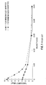
- Treno estimates the maximum throughput that a network can offer without any constraint being imposed based on the subscriber's terminal. This means that Treno does not impose a restriction on the TCP window size in use. As is known, typical TCP implementations at the ISS and the subscriber's terminal impose a bound on the TCP window size. Many personal computers bound this value to 8K bytes and the majority of workstations support window sizes up to 32K bytes. The TCP window size in use during a data transfer significantly impacts the network throughput observed by the subscribers. The effect of using different window sizes is best illustrated in Figure 1. Figure 1 shows the contrast between performance observed on the same network when using different maximum window size bounds. As can be seen from Figure 1, the larger window size offers much higher network throughput in most cases.
- Treno does not impose a restriction on the window size in use, it is clear from Figure 1 that Treno can significantly overestimate subscriber-perceived data transfer throughput.
- a further drawback of using unrestricted window size is that this typically causes the network to be flooded with test traffic which may significantly impact the performance observed by subscribers during the time the network is being tested. Consequently, rather than measuring subscriber satisfaction, the use of Treno may cause further subscriber dissatisfaction because of its impact on the network.
- the present invention seeks to provide an improved system of evaluating performance of a network.
- One feature of the preferred embodiment is to minimise test traffic in a network when evaluating data transfer throughput of the network. It can also accurately evaluate user-perceived network performance of a network with minimised test traffic in the network.
- the system has the ability to measure throughput observed by users by testing to user terminals or to special targets nodes in the network, without requiring any special software support at the user terminals or the target nodes.
- a preferred scheme of evaluating performance of a network connecting a remote terminal to a data service system emulates a communication protocol that transfers data reliably and in sequence with congestion control.
- the communication protocol includes mechanisms for acknowledgement and retransmission and a dynamic window size.
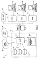
- the data access network system 50 also includes connections to a global Internet 30 and other ISSs 28 connected to the ISS 10.
- the other ISSs 28 may also include online service systems, such as America Online and Compuserve.
- the ISS 10 provides Internet or Intranet service to subscriber sites 12, 14, and 16 via an interconnect network 34.
- the ISS 10 may be within the premises of a cable operator, or may be a central office of a telephone carrier, or may be a local area network of a corporation, but this is not critical to the invention.
- the subscriber sites may include terminals of subscribers/users located at the residences, schools, or offices of the subscribers/users.
- the interconnect network 34 can be any known network.
- the interconnect network 34 is a LAN (Local Area Network) network using technologies such as Ethernet, FDDI, 100-VG, 100BaseT, and Asynchronous Transfer Mode (ATM).
- the interconnect network 34 is a WAN (Wide Area Network) such as a T-1 or T-3 link.
- the network 34 can be an access network to the home, such as an ISDN (Integrated Services Digital Network) network, an ADSL (Asymmetric Digital Subscriber Line) network, a HFC (Hybrid Fiber Coaxial) network, or a wireless LMDS (Local Multi-point Distribution Service) network.
- the interconnect network 34 can be other known network.
- Each of the subscriber sites 12, 14, and 16 may include a personal computer, a network computer, a notebook computer, a workstation, a mainframe computer, a supercomputer, or any other type of data processing system.
- modems 44-46 and or other network adapters (not shown) in modems' place receive and transmit data over the interconnect network 34.
- broadband modems e.g., cable modems for a hybrid fiber coaxial cable network
- the modems 44-46 can be located within or outside of their respective computers. The modems 44-46 may not be needed when the interconnect network 34 is, for example, a LAN network.
- the subscriber sites can serve as target sites for throughput measurements by the embodiment of throughput measurement systems 100 described below.
- the target sites may also be tested specifically installed in the ISS 10 to permit testing of the interconnect network 34.
- many more test targets may be used.
- the test targets e.g., test target 42
- the test targets also have network addresses, but they do not execute any additional special purpose software.
- the test targets perform known functions and have known performances.
- the throughput measurement system 100 can estimate the performance of the network 34 over time. By placing the test targets at carefully selected locations in the ISS 10 (e.g., on each of the branches of the hybrid fiber coaxial (HFC) cable interconnect network), the throughput measurement system 100 can test specific places in the network 34 more accurately.
- HFC hybrid fiber coaxial
- the ISS 10 includes a router 24 for routing data to and from the subscriber sites 12, 14 and 16 upon receiving a request from a subscriber/user.
- the router 24 functions to connect the subscriber sites 12, 14 and 16 to the appropriate on-premises servers 18, 20 and 22, or to the global Internet 30 or the other ISSs 28.
- the router 24 may operate in the Asynchronous Transfer Mode (ATM) to provide high bandwidth packet-based switching and multiplexing.
- ATM Asynchronous Transfer Mode
- the ISS 10 also includes content servers 18 and proxy servers 20.
- the ISS 10 includes other servers 22.
- the other servers 22 may include DNS (Domain Name Server), DHCP (Dynamic Host Configuration Protocol), and NAT (Network Address Translator) servers.
- DNS Domain Name Server
- DHCP Dynamic Host Configuration Protocol
- NAT Network Address Translator
- the content servers 18 support a variety of Internet applications, including World Wide Web access, electronic mail, bulletin boards, news groups and FTP access, all of which rely on the TCP/IP protocols for communication between the ISS servers and the remote terminals.
- the proxy servers 20 may be used to enhance security of accesses to and from the subscriber sites 12, 14, and 16, as well as to speed up Internet access by caching frequently accessed data locally. All of the servers 18, 20, and 22 are well known in the art.
- the throughput measurement system 100 is connected to router 24.
- the throughput measurement system 100 can access servers 18, 20, and 22 via the router 24. In another embodiment, the throughput measurement system 100 can be directly connected to the access servers 18, 20, and 22.
- the throughput measurement system 100 can also access the subscriber sites 12, 14, and 16 and the test targets 42 via the router 24 and the interconnect network 34.
- the throughput measurement system 100 can also be placed at other locations in the data access network system 50.
- the throughput measurement system may be located in the global Internet 30 or in the other ISSs 28 to measure the throughput to and from the global Internet and other ISSs.
- the throughput measurement system 100 evaluates subscriber perceived network performance between the ISS 10 and the subscriber sites 12, 14, and 16 and test target 42. These sites can be referred to as target sites. As will be described in more detail below, the throughput measurement system 100 emulates data transfers over TCP using the User Datagram Protocol (UDP) and Internet Control Message Protocol (ICMP) to transmit and receive packets, respectively, from the target sites 12, 14, 16, and 42, and calculates data transfer throughput to the target sites 12, 14, 16 and 42 with a restriction on the TCP window size. Data transfer throughput is the rate at which the system transfers data to and from the target sites 12, 14, 16 and 42. Throughput monitoring provides a means for evaluating the network performance.
- UDP User Datagram Protocol
- ICMP Internet Control Message Protocol
- the throughput measurement system 100 first selects a target site (e.g., subscriber site 12) for evaluation.
- the throughput measurement system 100 determines the maximum TCP window size setting to use for the throughput measurements either based on the network address of the subscriber site 12, or based on a pre-specified value (chosen based on typical maximum TCP window size settings at the subscriber sites 12, 14, and 16).
- the TCP window size indicates the number of unacknowledged data packets.
- the throughput measurement system 100 determines the maximum number of packets to be transmitted during the measurement.
- the throughput measurement system 100 then starts the evaluation process by sending UDP packets under a specified TCP window (or socket buffer) size to the target site 12.
- the throughput measurement system 100 uses UDP packets that are of the same size as TCP data packets, and targets these UDP packets at unused ports on the target site 12. These UDP packets evoke small ICMP error messages that emulate TCP acknowledgments for data packets from the target site 12. Based on the acknowledgments it receives, the throughput measurement system 100 emulates TCP congestion control algorithms (i.e., dynamically increasing or decreasing the window size based on the transmission result). The throughput measurement system 100 always makes sure that the dynamic window size used in the measurement is not greater than the predetermined maximum TCP window size (i.e., the TCP window size decided at the beginning of the measurement).
- TCP congestion control algorithms i.e., dynamically increasing or decreasing the window size based on the transmission result.
- the throughput measurement system 100 can emulate a typical data transfer and thereby, measure the network throughput accurately.
- the test terminates either when the pre-specified maximum number of data packets have been transmitted or when a pre-specified maximum duration of the test is exceeded.
- the throughput measurement system 100 reports the measured user-perceived throughput as well as the packet loss percentage seen during the test.
- Figure 3 illustrates the throughput and packet loss observed by actively testing a test target connected to a hybrid fiber coaxial cable network for a day. In this network, clearly during the period 10am-1pm, there is a significant drop in user-perceived network performance.
- the throughput measurement system 100 relies on the testing capabilities that are supported by any device that supports the IP (Internet Protocol), the throughput measurement system 100 can be used to measure performance of a variety of off-the-shelf devices, such as PCs, Macintosh computers, servers, and modems at the target sites 12, 14, 16, and 42 without requiring special-purpose software executing at these sites.
- off-the-shelf devices such as PCs, Macintosh computers, servers, and modems at the target sites 12, 14, 16, and 42 without requiring special-purpose software executing at these sites.
- the throughput measurement system 100 includes a computer system (not shown) that supports the IP (Internet Protocol) and a measurement system 102 (shown in Figure 4) that implements one embodiment of the present invention.
- the computer system can be any kind of computer system that is equipped with network access ability and supports the IP protocol.
- the measurement system 102 can be implemented by software, dedicated hardware, and/or firmware.
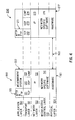
- Figure 4 shows various layers 150 through 154 of the throughput measurement system 100 and a target site 200 that can be any one of the target sites 12, 14, 16, and 42.
- the physical layer 154 indicates the hardware 161 and 217 of the throughput measurement system 100 and the target site 200, as well as the physical connection 160 of the network 34.
- the media access control layer 153 indicates a network specific software 141 and 216 for the throughput measurement system 100 and the target site 200.
- the network specific software programs 141 and 216 are specific to the network technology used.
- Above the media access control layer 153 is the network layer 152.
- both the throughput measurement system 100 and the target site 200 employ the IP protocol (i.e., 131 and 215).
- the throughput measurement system 100 also includes UDP 122, and ICMP 123 at the transport layer 151 which is above the network layer 152.
- the throughput measurement system 100 may also include TCP 121 transport layer.
- the target site 200 includes UDP 213, and ICMP 214 at the transport layer 151.
- the TCP layer 212 is optional.
- Above the transport layer 151 lies the application layer 150.
- the throughput measurement system 100 includes the measurement system 102 that is above the UDP 122 and ICMP 123.
- the throughput measurement system 100 optionally includes HTTP and FTP applications 101 that are above the TCP 121.
- the target site 200 does not include any special-purpose software above the UDP 122 and ICMP 123 to support the throughput measurements.
- the target site 200 may include HTTP and FTP applications 211 above the TCP 212. This is again optional.
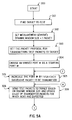
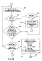
- Figures 5A-5D show in flow chart diagram form the process of the measurement system 102 in accordance with one embodiment of the present invention.
- the process starts at step 300.
- the target site e.g., subscriber site 12
- the measurement system 102 determines the maximum window size setting to use for the measurement. This value is then used as the maximum TCP window size of the measurement system 102 during testing.
- the measurement system 102 also determines the packet size, the number of packets to be transmitted, and the maximum test time (i.e., the maximum time allowed for transmission).
- the measurement system 102 initially sets a dynamic window size that it uses to emulate TCP to one packet. Alternatively, the measurement system 102 may sets its initial window size to a value that is greater or less than one, depending on the protocol and its specific implementation that is to be emulated.
- the measurement system 102 decides the packet protocol for transmitting the test packets to the target remote site. In one embodiment, the packet protocol employed is the UDP/ICMP protocols. Alternatively, other known data transfer protocols can be used.
- an unused port number is selected as the starting port number of the packets to be transmitted.
- the port number is used here to identify the sequence of the packets to be transmitted.
- the port number is incremented by one for each successive packet to be transmitted.
- the packets are sent to the target remote site based on the specified window size at step 306.
- the list of transmitted packets for which acknowledgments (ACKs) are expected in the measurement system 102 is updated (In the current context, the term ACK refers to ICMP unreachable error messages from the target site that emulate TCP acknowledgments).
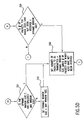
- step 307 is executed at which the measurement system 102 waits for an ACK to arrive within a predetermined response time period.
- the response time period itself may also be dynamically updated by the measurement server, by measuring the delay between transmission of a packet and the receipt of the corresponding ACK.
- Step 308 is a judgement step that follows step 307. If, at step 308, it is determined that the ACK of any transmitted packet has not been received within the predetermined response time (this means that some packets or their ACKs have been lost during transmission over the network), the process goes to step 309. Otherwise, the process continues at step 320.
- step 309 it is determined whether the total time from the start of the test is greater than or equal to the predetermined maximum test time. If the answer is no, then step 310 is executed to decrease the dynamic window size and then retransmit the packets. If the answer is yes, then step 311 is executed.
- the dynamic window size is decreased in accordance with a TCP's window adjustment algorithm.
- the TCP's window adjustment algorithm allows the dynamic window size to be increased or decreased by one, or by a magnitude of two (i.e., double or half). The process then moves to step 325.
- the TCP's window adjustment algorithm is known in the art.
- step 311 the total time from the start of the test is obtained and the user-perceived throughput is computed by multiplying the number of ACKs received with the size of the data packets and dividing by the total time for the measurement. This means that the data transfer throughput is obtained at this step. Based on the ACKs received and the packets transmitted, the packet loss percentage during the test is also computed. The process then ends at step 312.
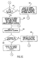
- Step 320 is also a judgement step that determines whether the pre-specified number of packets have been transmitted and ACKs are received in the measurement system 102 for all transmitted packets, or alternatively whether the total time is greater than or equal to the maximum test time. If the answer is yes for either question. then step 311 is executed. Otherwise, step 321 is executed to determine if the received port number of the ACK is in the range of the port numbers of the transmitted packets. If the answer is no (indicating that an unexpected ACK has been received by the measurement system 102), the process returns to step 307 to continue its wait. Otherwise, step 322 is executed to determine if the port numbers of the ACK are in sequence.
- step 322 it is determined that the port numbers of the ACKs are in sequence (indicating that the transmitted packets are being received by the target site without any loss), the dynamic window size needs to be increased and step 323 is executed. If the answer is no, it means that packet loss has probably occurred and the dynamic window size needs to be reduced at step 324.
- step 323 the dynamic window size is increased in accordance with the TCP window adjustment algorithm. Then step 331 is executed.
- the number of missing packets i.e., the number of transmitted packets that may have been lost during transmission over the network
- the dynamic window size is decreased if necessary (this is determined based on TCP's window size adjustment algorithm).
- the TCP retransmission algorithm is applied.
- step 326 is executed, at which it is determined whether to retransmit the missing packets. If the answer is no, step 328 is then executed. If the answer is yes, step 327 is then executed to decide the port numbers to use for retransmitting the missing packets. The process then returns to step 306 to send the missing packets.
- step 328 the number of packets for which ACKs have not yet been received by the measurement system 102 is computed. Then step 329 is executed to determine if additional packets can be transmitted by comparing the number of packets for which ACKs have not been received with the dynamic window size. If the answer is no, then the process returns to step 307. If the answer is yes, then step 330 is executed to set the number of packets to be transmitted to be equal to the dynamic window size minus the number of unacknowledged packets. Then the process returns to step 305.
- Step 331 follows step 323. Step 331 determines whether the increased dynamic window size is still less than or equal to the predetermined TCP's maximum window size. If yes, the process moves to step 330. If the answer is no, then the increased dynamic window size is reset to equal to the maximum window size. Steps 331 and 332 provide a mechanism that allows the testing to emulate the behavior of TCP as it impacts the users. These steps also ensure that the testing does not flood the interconnect network 34 while accurately
Abstract
Description
Claims (6)
- A method of evaluating performance of a network (34) connecting a terminal (12, 14, 16, 42) to a data service system (10), comprising:(A) emulating a communication protocol to transfer data reliably and in sequence with congestion control, wherein the communication protocol includes mechanisms for acknowledgement and retransmission and a dynamic window size;(B) restricting the dynamic window size not to be greater than a predetermined maximum window size.
- , A method as in claim 1, comprising the step of restricting the data transfer not to exceed a predetermined maximum amount of data.
- A method as in claim 1 or 2, wherein the network is selected from a number of network technologies comprising Ethernet, FDDI, 100-VG, 100 BaseT, ATM, T-1, T-3, an integrated services digital network, an asymmetric digital subscriber line network, a hybird fiber coaxial network, a wireless local multi-point distribution service network, and/or a combination thereof.
- A method as in claim 1, 2 or 3, wherein the terminal (12, 14. 16, 42) is a computer system (12, 14, 16).
- A method as in preceeding claim, wherein the terminal (12, 14, 16, 42) is a computer system (12, 14, 16) with a modem (44-46).
- A method as in any one of claims 1 to 4, wherein the terminal (12, 14, 16, 42) is one of a modem (44-46), a test target (42), a network adapter.
Applications Claiming Priority (2)
| Application Number | Priority Date | Filing Date | Title |
|---|---|---|---|
| US08/827,789 US6076113A (en) | 1997-04-11 | 1997-04-11 | Method and system for evaluating user-perceived network performance |
| US827789 | 1997-04-11 |
Publications (2)
| Publication Number | Publication Date |
|---|---|
| EP0871306A2 true EP0871306A2 (en) | 1998-10-14 |
| EP0871306A3 EP0871306A3 (en) | 2000-12-27 |
Family
ID=25250178
Family Applications (1)
| Application Number | Title | Priority Date | Filing Date |
|---|---|---|---|
| EP98302781A Withdrawn EP0871306A3 (en) | 1997-04-11 | 1998-04-09 | Method and system for evaluating network performance |
Country Status (3)
| Country | Link |
|---|---|
| US (1) | US6076113A (en) |
| EP (1) | EP0871306A3 (en) |
| JP (1) | JPH10303902A (en) |
Cited By (5)
| Publication number | Priority date | Publication date | Assignee | Title |
|---|---|---|---|---|
| KR20010103247A (en) * | 2000-05-09 | 2001-11-23 | 조용인 | Method and system for providing ip network traffic measurement |
| WO2003050681A1 (en) * | 2001-12-12 | 2003-06-19 | Unisys Corporation | A method of and apparatus for testing a server |
| EP1488246A1 (en) * | 2002-03-20 | 2004-12-22 | Sunrise Telecom Incorporated | System and method for monitoring a packet network |
| EP1548972A3 (en) * | 2003-12-26 | 2006-12-27 | NTT DoCoMo, Inc. | Transmitter device and relay device for performing data transmission control |
| DE19983404B4 (en) * | 1998-07-07 | 2009-08-27 | Nokia Networks Oy | Method and apparatus for use in setting a TCP sliding window |
Families Citing this family (63)
| Publication number | Priority date | Publication date | Assignee | Title |
|---|---|---|---|---|
| US6473793B1 (en) * | 1994-06-08 | 2002-10-29 | Hughes Electronics Corporation | Method and apparatus for selectively allocating and enforcing bandwidth usage requirements on network users |
| DE19730159B4 (en) * | 1997-07-14 | 2006-01-19 | Telefonaktiebolaget Lm Ericsson (Publ) | Communication method and system |
| US6192412B1 (en) * | 1998-07-28 | 2001-02-20 | Lucent Technologies, Inc. | Computer file transmission system and method |
| US6308209B1 (en) * | 1998-10-22 | 2001-10-23 | Electronic Data Systems Corporation | Method and system for measuring usage of a computer network by a network user |
| US6531717B1 (en) * | 1999-03-01 | 2003-03-11 | Teccor Electronics, L.P. | Very low voltage actuated thyristor with centrally-located offset buried region |
| US6380971B1 (en) * | 1999-05-28 | 2002-04-30 | Qwest Communications International Inc. | VDSL video/data set top test equipment |
| US6859462B1 (en) * | 1999-08-10 | 2005-02-22 | Orative Corporation | Minimization and optimization of overall data transfer connect time between handheld wireless communicating devices and remote machines |
| US6598028B1 (en) * | 1999-09-03 | 2003-07-22 | Lynn Sullivan | Computer-implemented universal financial management/translation system and method |
| KR100363517B1 (en) * | 1999-12-23 | 2002-12-05 | 엘지전자 주식회사 | Method For Monitoring Network State And Apparatus Thereof |
| US6973497B1 (en) * | 2000-02-10 | 2005-12-06 | Hughes Electronics Corporation | Selective spoofer and method of performing selective spoofing |
| US7082467B2 (en) * | 2000-02-10 | 2006-07-25 | Hughes Network Systems | Method and device for selective transport level spoofing based on information in transport level packet |
| US6591298B1 (en) * | 2000-04-24 | 2003-07-08 | Keynote Systems, Inc. | Method and system for scheduling measurement of site performance over the internet |
| US6842769B1 (en) * | 2000-05-05 | 2005-01-11 | Interland, Inc. | Automatically configured network server |
| US6925502B1 (en) * | 2000-06-20 | 2005-08-02 | At&T Corp. | Methods and systems for improving data transmission rates having adaptive protocols |
| US6839754B2 (en) * | 2000-09-15 | 2005-01-04 | Wm. Marsh Rice University | Network tomography using closely-spaced unicast packets |
| WO2002033901A2 (en) * | 2000-10-17 | 2002-04-25 | Sprint Communications Company, L.P. | Performance management system |
| US20020133614A1 (en) * | 2001-02-01 | 2002-09-19 | Samaradasa Weerahandi | System and method for remotely estimating bandwidth between internet nodes |
| US20020167942A1 (en) * | 2001-05-04 | 2002-11-14 | Cathy Fulton | Server-site response time computation for arbitrary applications |
| US7123933B2 (en) * | 2001-05-31 | 2006-10-17 | Orative Corporation | System and method for remote application management of a wireless device |
| US20020180798A1 (en) * | 2001-05-31 | 2002-12-05 | Poor Graham V. | System and method for extending a wireless device platform to multiple applications |
| US7020457B2 (en) * | 2001-05-31 | 2006-03-28 | Orative Corporation | System and method for proxy-enabling a wireless device to an existing IP-based service |
| US7043560B2 (en) * | 2001-06-19 | 2006-05-09 | Nokia, Inc. | Dynamic probing and reporting of bit rate information |
| US7006526B1 (en) | 2001-07-31 | 2006-02-28 | Cisco Technology, Inc. | Mechanisms for avoiding problems associated with network address protocol translation |
| US20030046383A1 (en) * | 2001-09-05 | 2003-03-06 | Microsoft Corporation | Method and system for measuring network performance from a server |
| US7237007B2 (en) * | 2001-12-05 | 2007-06-26 | Qualcomm Incorporated | Method and system for flow control between a base station controller and a base transceiver station |
| US20030117959A1 (en) * | 2001-12-10 | 2003-06-26 | Igor Taranov | Methods and apparatus for placement of test packets onto a data communication network |
| US7197571B2 (en) * | 2001-12-29 | 2007-03-27 | International Business Machines Corporation | System and method for improving backup performance of media and dynamic ready to transfer control mechanism |
| US7542471B2 (en) | 2002-10-30 | 2009-06-02 | Citrix Systems, Inc. | Method of determining path maximum transmission unit |
| US8233392B2 (en) | 2003-07-29 | 2012-07-31 | Citrix Systems, Inc. | Transaction boundary detection for reduction in timeout penalties |
| US7630305B2 (en) | 2003-07-29 | 2009-12-08 | Orbital Data Corporation | TCP selective acknowledgements for communicating delivered and missed data packets |
| US7616638B2 (en) | 2003-07-29 | 2009-11-10 | Orbital Data Corporation | Wavefront detection and disambiguation of acknowledgments |
| US8270423B2 (en) | 2003-07-29 | 2012-09-18 | Citrix Systems, Inc. | Systems and methods of using packet boundaries for reduction in timeout prevention |
| US7081674B2 (en) * | 2003-06-13 | 2006-07-25 | Rensselaer Polytechnic Institute | Polyelectrolyte nanolayers as diffusion barriers in semiconductor devices |
| US8238241B2 (en) | 2003-07-29 | 2012-08-07 | Citrix Systems, Inc. | Automatic detection and window virtualization for flow control |
| US8437284B2 (en) | 2003-07-29 | 2013-05-07 | Citrix Systems, Inc. | Systems and methods for additional retransmissions of dropped packets |
| US7698453B2 (en) * | 2003-07-29 | 2010-04-13 | Oribital Data Corporation | Early generation of acknowledgements for flow control |
| US8432800B2 (en) | 2003-07-29 | 2013-04-30 | Citrix Systems, Inc. | Systems and methods for stochastic-based quality of service |
| US7656799B2 (en) | 2003-07-29 | 2010-02-02 | Citrix Systems, Inc. | Flow control system architecture |
| US20050068891A1 (en) * | 2003-09-25 | 2005-03-31 | Arsikere Amarnath R. | Method and apparatus for network throughput measurement |
| US20050262237A1 (en) * | 2004-04-19 | 2005-11-24 | Netqos, Inc. | Dynamic incident tracking and investigation in service monitors |
| US8090837B2 (en) | 2004-05-27 | 2012-01-03 | Hewlett-Packard Development Company, L.P. | Communication in multiprocessor using proxy sockets |
| US8761202B2 (en) * | 2004-09-27 | 2014-06-24 | Raghupathy Sivakumar | Architecture for dynamically adaptive transport protocols |
| US20060123393A1 (en) * | 2004-12-02 | 2006-06-08 | Brian Atkins | User interface for network application |
| US20060198300A1 (en) * | 2005-03-03 | 2006-09-07 | Chia-Hsin Li | Multi-channel TCP connections with congestion feedback for video/audio data transmission |
| US7907966B1 (en) | 2005-07-19 | 2011-03-15 | Aol Inc. | System and method for cross-platform applications on a wireless phone |
| JP5124455B2 (en) * | 2005-07-28 | 2013-01-23 | エムフォメーション・テクノロジーズ・インコーポレイテッド | System and method for remotely controlling device functionality |
| WO2007016337A2 (en) * | 2005-07-28 | 2007-02-08 | Mformation Technologies, Inc. | System and method for service quality management for wireless devices |
| US8159943B2 (en) * | 2005-09-16 | 2012-04-17 | Jds Uniphase Corporation | Method of forming protocol data units, protocol data units and protocol data unit generation apparatus |
| US20070230413A1 (en) * | 2006-03-30 | 2007-10-04 | Lucent Technologies Inc. | Method for measuring airlink transmission latency in a 1x-EVDO wireless network |
| US9258230B2 (en) * | 2006-10-17 | 2016-02-09 | Hewlett Packard Enterprise Development Lp | In flight TCP window adjustment to improve network performance |
| US20080148293A1 (en) * | 2006-10-17 | 2008-06-19 | Adrian Cowham | Configurable event broker |
| US7706266B2 (en) | 2007-03-12 | 2010-04-27 | Citrix Systems, Inc. | Systems and methods of providing proxy-based quality of service |
| US7856574B2 (en) * | 2007-09-27 | 2010-12-21 | Microsoft Corporation | Internet connectivity evaluation |
| WO2009059851A1 (en) * | 2007-11-09 | 2009-05-14 | Nokia Corporation | Method, apparatus and software for packet modification |
| US20100008248A1 (en) * | 2008-07-08 | 2010-01-14 | Barry Constantine | Network tester for real-time measuring of tcp throughput |
| JP2010102553A (en) * | 2008-10-24 | 2010-05-06 | Nec Corp | Terminal device, server client system, terminal control program, and terminal control method |
| GB0919655D0 (en) * | 2009-11-10 | 2009-12-23 | Ciqual Ltd | Methods and apparatus for monitoring network link quality |
| US8995630B1 (en) | 2010-08-01 | 2015-03-31 | Tulsa Holdings, Llc | Telephony and applications communication in a non-mobile telephone system |
| CN102035857B (en) * | 2010-12-31 | 2013-10-16 | 北京像素软件科技股份有限公司 | Method for simulating group self-organization behaviors of multiple game characters |
| CN107638428B (en) | 2011-05-19 | 2021-07-23 | 麦瑟布莱斯特公司 | Methods for treating obesity and/or metabolic syndrome |
| US8626910B1 (en) | 2012-06-19 | 2014-01-07 | Edgecast Networks, Inc. | Systems and methods for performing localized server-side monitoring in a content delivery network |
| US10834065B1 (en) | 2015-03-31 | 2020-11-10 | F5 Networks, Inc. | Methods for SSL protected NTLM re-authentication and devices thereof |
| US10404698B1 (en) | 2016-01-15 | 2019-09-03 | F5 Networks, Inc. | Methods for adaptive organization of web application access points in webtops and devices thereof |
Citations (1)
| Publication number | Priority date | Publication date | Assignee | Title |
|---|---|---|---|---|
| EP0687090A2 (en) * | 1989-11-30 | 1995-12-13 | AT&T Corp. | Dynamic window sizing in a data network |
Family Cites Families (1)
| Publication number | Priority date | Publication date | Assignee | Title |
|---|---|---|---|---|
| US5197127A (en) * | 1990-09-24 | 1993-03-23 | International Business Machines Corporation | Expert system method for performing window protocol-based data flow analysis within a data communication network |
-
1997
- 1997-04-11 US US08/827,789 patent/US6076113A/en not_active Expired - Fee Related
-
1998
- 1998-04-09 EP EP98302781A patent/EP0871306A3/en not_active Withdrawn
- 1998-04-13 JP JP10087198A patent/JPH10303902A/en active Pending
Patent Citations (1)
| Publication number | Priority date | Publication date | Assignee | Title |
|---|---|---|---|---|
| EP0687090A2 (en) * | 1989-11-30 | 1995-12-13 | AT&T Corp. | Dynamic window sizing in a data network |
Non-Patent Citations (1)
| Title |
|---|
| MILOUCHEVA I ET AL: "PROTOCOL MECHANISMS FOR RELIABLE TRANSMISSION AND FLOW CONTROL ON MULTIMEDIA HIGHWAYS" PROCEEDINGS OF THE IEEE ANNUAL INTERNATIONAL PHOENIX CONFERENCE ON COMPUTERS AND COMMUNICATIONS,US,NEW YORK, IEEE, vol. CONF. 15, 27 March 1996 (1996-03-27), pages 239-245, XP000594795 ISBN: 0-7803-3256-3 * |
Cited By (9)
| Publication number | Priority date | Publication date | Assignee | Title |
|---|---|---|---|---|
| DE19983404B4 (en) * | 1998-07-07 | 2009-08-27 | Nokia Networks Oy | Method and apparatus for use in setting a TCP sliding window |
| KR20010103247A (en) * | 2000-05-09 | 2001-11-23 | 조용인 | Method and system for providing ip network traffic measurement |
| WO2003050681A1 (en) * | 2001-12-12 | 2003-06-19 | Unisys Corporation | A method of and apparatus for testing a server |
| US7284161B2 (en) | 2001-12-12 | 2007-10-16 | Unisys Corporation | Method of and apparatus for testing a server |
| EP1488246A1 (en) * | 2002-03-20 | 2004-12-22 | Sunrise Telecom Incorporated | System and method for monitoring a packet network |
| EP1488246A4 (en) * | 2002-03-20 | 2007-03-14 | Sunrise Telecom Inc | System and method for monitoring a packet network |
| EP1548972A3 (en) * | 2003-12-26 | 2006-12-27 | NTT DoCoMo, Inc. | Transmitter device and relay device for performing data transmission control |
| CN100466586C (en) * | 2003-12-26 | 2009-03-04 | 株式会社Ntt都科摩 | Transmitter device and relay device for performing data transmission control |
| US7680141B2 (en) | 2003-12-26 | 2010-03-16 | Ntt Docomo, Inc. | Transmitter device and relay device for performing data transmission control |
Also Published As
| Publication number | Publication date |
|---|---|
| EP0871306A3 (en) | 2000-12-27 |
| JPH10303902A (en) | 1998-11-13 |
| US6076113A (en) | 2000-06-13 |
Similar Documents
| Publication | Publication Date | Title |
|---|---|---|
| US6076113A (en) | Method and system for evaluating user-perceived network performance | |
| Savage | Sting: A TCP-based Network Measurement Tool. | |
| Dukkipati et al. | An argument for increasing TCP's initial congestion window | |
| Prasad et al. | Bandwidth estimation: metrics, measurement techniques, and tools | |
| Allman et al. | An evaluation of TCP with larger initial windows | |
| US6643259B1 (en) | Method for optimizing data transfer in a data network | |
| Casetti et al. | TCP Westwood: end-to-end congestion control for wired/wireless networks | |
| Duke et al. | A roadmap for transmission control protocol (TCP) specification documents | |
| US7995478B2 (en) | Network communication with path MTU size discovery | |
| US7564781B2 (en) | Determining throughput between hosts | |
| Liu et al. | Congestion control without a startup phase | |
| Henderson et al. | Satellite transport protocol (STP): An SSCOP-based transport protocol for datagram satellite networks | |
| Mathis et al. | TCP extended statistics MIB | |
| Caro et al. | Retransmission policies with transport layer multihoming | |
| Argyriou et al. | Bandwidth aggregation with SCTP | |
| Ming-Chit et al. | Improving TCP performance over asymmetric networks | |
| Man et al. | ImTCP: TCP with an inline measurement mechanism for available bandwidth | |
| Mandalari et al. | Measuring ECN++: good news for++, bad news for ECN over mobile | |
| Ke et al. | Towards a Rate-based TCP Protocol for the Web | |
| Le Thanh Man et al. | A new available bandwidth measurement technique for service overlay networks | |
| Haeberlen et al. | Monarch: a tool to emulate transport protocol flowsover the internet at large | |
| Cisco | Appendix A: ADSL Technology Glossary | |
| Cisco | ADSL Technology Glossary | |
| Cisco | Glossary | |
| Cisco | Appendix D: ADSL Technology Glossary |
Legal Events
| Date | Code | Title | Description |
|---|---|---|---|
| PUAI | Public reference made under article 153(3) epc to a published international application that has entered the european phase |
Free format text: ORIGINAL CODE: 0009012 |
|
| AK | Designated contracting states |
Kind code of ref document: A2 Designated state(s): AT BE CH CY DE DK ES FI FR GB GR IE IT LI LU MC NL PT SE |
|
| AX | Request for extension of the european patent |
Free format text: AL;LT;LV;MK;RO;SI |
|
| RIN1 | Information on inventor provided before grant (corrected) |
Inventor name: PERRY, EDWARD H. Inventor name: RAMANATHAN, SRINIVAS |
|
| PUAL | Search report despatched |
Free format text: ORIGINAL CODE: 0009013 |
|
| AK | Designated contracting states |
Kind code of ref document: A3 Designated state(s): AT BE CH CY DE DK ES FI FR GB GR IE IT LI LU MC NL PT SE |
|
| AX | Request for extension of the european patent |
Free format text: AL;LT;LV;MK;RO;SI |
|
| RAP1 | Party data changed (applicant data changed or rights of an application transferred) |
Owner name: HEWLETT-PACKARD COMPANY, A DELAWARE CORPORATION |
|
| RAP1 | Party data changed (applicant data changed or rights of an application transferred) |
Owner name: AGILENT TECHNOLOGIES, INC. Owner name: HEWLETT-PACKARD COMPANY, A DELAWARE CORPORATION |
|
| RAP1 | Party data changed (applicant data changed or rights of an application transferred) |
Owner name: AGILENT TECHNOLOGIES, INC. |
|
| RAP1 | Party data changed (applicant data changed or rights of an application transferred) |
Owner name: AGILENT TECHNOLOGIES INC. |
|
| RAP1 | Party data changed (applicant data changed or rights of an application transferred) |
Owner name: AGILENT TECHNOLOGIES INC. A DELAWARE CORPORATION |
|
| AKX | Designation fees paid | ||
| RAP1 | Party data changed (applicant data changed or rights of an application transferred) |
Owner name: AGILENT TECHNOLOGIES, INC. (A DELAWARE CORPORATION |
|
| REG | Reference to a national code |
Ref country code: DE Ref legal event code: 8566 |
|
| RAP1 | Party data changed (applicant data changed or rights of an application transferred) |
Owner name: HEWLETT-PACKARD COMPANY (A DELAWARE CORPORATION) Owner name: AGILENT TECHNOLOGIES, INC. (A DELAWARE CORPORATION |
|
| STAA | Information on the status of an ep patent application or granted ep patent |
Free format text: STATUS: THE APPLICATION IS DEEMED TO BE WITHDRAWN |
|
| 18D | Application deemed to be withdrawn |
Effective date: 20010628 |
|
| RIN1 | Information on inventor provided before grant (corrected) |
Inventor name: PERRY, EDWARD H. Inventor name: RAMANATHAN, SRINIVAS |