EP0873918A2 - Control system for apparatus for protecting head portion of vehicle occupant - Google Patents
Control system for apparatus for protecting head portion of vehicle occupant Download PDFInfo
- Publication number
- EP0873918A2 EP0873918A2 EP98105300A EP98105300A EP0873918A2 EP 0873918 A2 EP0873918 A2 EP 0873918A2 EP 98105300 A EP98105300 A EP 98105300A EP 98105300 A EP98105300 A EP 98105300A EP 0873918 A2 EP0873918 A2 EP 0873918A2
- Authority
- EP
- European Patent Office
- Prior art keywords
- air bag
- roll
- vehicle
- pretensioner
- head portion
- Prior art date
- Legal status (The legal status is an assumption and is not a legal conclusion. Google has not performed a legal analysis and makes no representation as to the accuracy of the status listed.)
- Granted
Links
Images


Classifications
-
- B—PERFORMING OPERATIONS; TRANSPORTING
- B60—VEHICLES IN GENERAL
- B60R—VEHICLES, VEHICLE FITTINGS, OR VEHICLE PARTS, NOT OTHERWISE PROVIDED FOR
- B60R21/00—Arrangements or fittings on vehicles for protecting or preventing injuries to occupants or pedestrians in case of accidents or other traffic risks
- B60R21/01—Electrical circuits for triggering passive safety arrangements, e.g. airbags, safety belt tighteners, in case of vehicle accidents or impending vehicle accidents
- B60R21/013—Electrical circuits for triggering passive safety arrangements, e.g. airbags, safety belt tighteners, in case of vehicle accidents or impending vehicle accidents including means for detecting collisions, impending collisions or roll-over
-
- B—PERFORMING OPERATIONS; TRANSPORTING
- B60—VEHICLES IN GENERAL
- B60R—VEHICLES, VEHICLE FITTINGS, OR VEHICLE PARTS, NOT OTHERWISE PROVIDED FOR
- B60R21/00—Arrangements or fittings on vehicles for protecting or preventing injuries to occupants or pedestrians in case of accidents or other traffic risks
- B60R21/01—Electrical circuits for triggering passive safety arrangements, e.g. airbags, safety belt tighteners, in case of vehicle accidents or impending vehicle accidents
- B60R21/013—Electrical circuits for triggering passive safety arrangements, e.g. airbags, safety belt tighteners, in case of vehicle accidents or impending vehicle accidents including means for detecting collisions, impending collisions or roll-over
- B60R2021/01306—Electrical circuits for triggering passive safety arrangements, e.g. airbags, safety belt tighteners, in case of vehicle accidents or impending vehicle accidents including means for detecting collisions, impending collisions or roll-over monitoring vehicle inclination
-
- B—PERFORMING OPERATIONS; TRANSPORTING
- B60—VEHICLES IN GENERAL
- B60R—VEHICLES, VEHICLE FITTINGS, OR VEHICLE PARTS, NOT OTHERWISE PROVIDED FOR
- B60R21/00—Arrangements or fittings on vehicles for protecting or preventing injuries to occupants or pedestrians in case of accidents or other traffic risks
- B60R21/01—Electrical circuits for triggering passive safety arrangements, e.g. airbags, safety belt tighteners, in case of vehicle accidents or impending vehicle accidents
- B60R21/013—Electrical circuits for triggering passive safety arrangements, e.g. airbags, safety belt tighteners, in case of vehicle accidents or impending vehicle accidents including means for detecting collisions, impending collisions or roll-over
- B60R21/0136—Electrical circuits for triggering passive safety arrangements, e.g. airbags, safety belt tighteners, in case of vehicle accidents or impending vehicle accidents including means for detecting collisions, impending collisions or roll-over responsive to actual contact with an obstacle, e.g. to vehicle deformation, bumper displacement or bumper velocity relative to the vehicle
-
- B—PERFORMING OPERATIONS; TRANSPORTING
- B60—VEHICLES IN GENERAL
- B60R—VEHICLES, VEHICLE FITTINGS, OR VEHICLE PARTS, NOT OTHERWISE PROVIDED FOR
- B60R21/00—Arrangements or fittings on vehicles for protecting or preventing injuries to occupants or pedestrians in case of accidents or other traffic risks
- B60R21/02—Occupant safety arrangements or fittings, e.g. crash pads
- B60R21/16—Inflatable occupant restraints or confinements designed to inflate upon impact or impending impact, e.g. air bags
- B60R21/23—Inflatable members
- B60R21/231—Inflatable members characterised by their shape, construction or spatial configuration
- B60R21/232—Curtain-type airbags deploying mainly in a vertical direction from their top edge
Definitions
- the present invention relates to a control system for an apparatus for protecting the head portion of a vehicle occupant which, at the time a predetermined high load is applied to a side portion of a vehicle body, jets gas from an inflator so as to inflate an air bag body in a curtain-like shape from a front pillar portion along a roof side rail portion due to the gas.
- Control systems for apparatuses for protecting the head portion of a vehicle occupant which, in order to improve the vehicle occupant head portion protecting performance at the time when a predetermined high load is applied to a side portion of the vehicle, inflate, in a curtain-like shape and along a window glass, an air bag body which is accommodated in a folded-up state so as to extend from the front pillar portion along the roof side rail portion.
- the structure described in WO 96/26087 which discloses such a control system for an apparatus for protecting the head portion of a vehicle occupant, will be described hereinafter.
- a vehicle occupant protecting apparatus 100 includes as the main structural components thereof an elongated duct 106, an air bag body 112, an inflator 116, and a belt-like strap 118.
- the elongated duct 106 is disposed so as to extend from a front pillar portion 102 along the roof side rail portion 104.
- the air bag body 112 is accommodated within the duct 106 in a folded-up state, and is fixed to the vehicle at a front end fixing point 108 and a rear end fixing point 110.
- the inflator 116 is connected to the rear end portion of the duct 106 via a hose 114, and jets gas at the time a predetermined high load is applied to a side portion of the vehicle.
- the air bag body 112 is formed by connecting a plurality of cells 120 which are each formed in a substantially cylindrical configuration and which are disposed such that the longitudinal directions thereof are substantially the vertical direction of the vehicle.
- the inflator 116 when a predetermined high load is applied to a side portion of the vehicle, gas is jetted out from the inflator 116.
- the jetted gas flows, via the hose 114 and the duct 106, into the respective cells 120 of the air bag body 112 which is folded up.
- the cells 120 inflate into substantially cylindrical shapes whose longitudinal directions are substantially the vertical direction of the vehicle.
- the air bag body 112 thereby inflates in a curtain-like shape along a window glass 122.
- the rear end portion of the air bag body 112 is connected to the vehicle via the strap 118, the rear end side of the air bag body 112 is reliably disposed at the inner side of the upper portion of a center pillar portion 124.
- the air bag body 112 inflates and unfolds between the head portion of the vehicle occupant and a portion of the vehicle, e.g., the side door glass. Therefore, if the vehicle is turning or a roll is generated at the vehicle or the like, because the vehicle occupant is swung toward the side portion of the vehicle, the gap between the vehicle occupant and the side portion of the vehicle, i.e., the space for the unfolding of the air bag body 112, becomes small.
- an object of the present invention is to provide a control system for an apparatus for protecting the head portion of a vehicle occupant in which the space for the unfolding of the air bag body is ensured and the air bag body can reliably unfold.
- the control system for an apparatus for protecting a head portion of a vehicle occupant of a first aspect of the present invention comprises: an air bag device having an air bag body for protecting a head portion of a vehicle occupant, the air bag body being accommodated so as to extend from a front pillar along a roof side rail and, upon operation, inflating and unfolding between the head portion of the vehicle occupant and a side portion of a vehicle; a pretensioner which, upon operation, takes-up slack of a seat belt fastened to the vehicle occupant; roll state detecting means for detecting a roll state of the vehicle; and control means for, in a case in which a roll state detected by the roll state detecting means is a predetermined roll state, controlling operation of the air bag device and operation of the pretensioner such that the pretensioner is operated before the air bag device is operated.
- the control means operates the pretensioner before operation of the air bag device, i.e., before the head portion protecting air bag body unfolds.
- the vehicle occupant can be maintained in the proper seating posture by the seat belt. Therefore, a space for the unfolding of the air bag body can be ensured between the head portion of the vehicle occupant and the side portion of the vehicle, and the air bag body can be reliably unfolded.
- the roll state detecting means is a roll angular velocity sensor which detects, as a roll state of the vehicle, a roll rate which is a rotational angular velocity around a longitudinal axis of the vehicle, and the control means computes a roll angle on the basis of the detected roll rate, and controls the operation of the air bag device and the operation of the pretensioner on the basis of a relationship between the detected roll rate and the computed roll angle.
- the control means operates the pretensioner before operation of the air bag device, i.e., before the head portion protecting air bag body unfolds.
- Fig. 1 is a flowchart illustrating control of operation of a pretensioner and an air bag device of a control system for an apparatus for protecting the head portion of a vehicle occupant relating to an embodiment of the present invention.
- Fig. 2 is a block diagram illustrating the structure of the control system for an apparatus for protecting the head portion of a vehicle occupant relating to the embodiment of the present invention.
- Fig. 3 is a schematic structural view, as seen from the side, of the regions of placement of main portions of the control system for an apparatus for protecting the head portion of a vehicle occupant relating to the embodiment of the present invention.
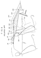
- Fig. 4 is a schematic structural view corresponding to Fig. 3 and illustrating a state in which an air bag body is inflated in the control system for an apparatus for protecting the head portion of a vehicle occupant relating to the embodiment of the present invention.
- Fig. 5 is a map illustrating the relationship between roll rates and roll angles at the control system for an apparatus for protecting the head portion of a vehicle occupant relating to the embodiment of the present invention.
- Fig. 6 is a schematic side view illustrating a control system for an apparatus for protecting the head portion of a vehicle occupant relating to a conventional embodiment.
- arrow FR indicates the frontward direction of the vehicle
- arrow UP indicates the upward direction of the vehicle
- the control system for an apparatus for protecting the head portion of a vehicle occupant of the present embodiment is provided with a head portion protecting air bag device 10.
- the air bag device 10 includes as main structural elements thereof a side collision sensor 12 which detects that there is a side collision, an inflator 14 which jets gas upon operation thereof, an air bag body 16 for protecting a head portion, the air bag body 16 being folded up by a predetermined way of folding, and a control circuit 17 serving as a control means and controlling operation of the inflator 14.
- control system for an apparatus for protecting the head portion of a vehicle occupant of the present embodiment includes a roll angular velocity sensor 13 and a pretensioner 15.
- the roll angular velocity sensor 13 serves as a roll state detecting means and detects the roll rate which is the rotational angular velocity around the longitudinal axis of the vehicle.
- the pretensioner 15 takes up the slack of a seat belt 11 upon operation of the pretensioner 15. The operation of the pretensioner 15 is also controlled by the control circuit 17.
- the side collision sensor 12 is disposed in a vicinity of a lower end portion of a center pillar (B pillar) 18, and detects that there is a side collision in a case in which a side collision load of a predetermined value or greater is applied to a side portion of the vehicle.
- a known sensor of a type which detects the rotational angular velocity by using the Coriolis force may be used as the roll angular velocity sensor 13.
- the average value after rectifying detected voltages is outputted to the control circuit 17 as the roll rate (RR).
- an acceleration sensor or a gas gyro or the like which detects the force generated by a predetermined mass in accordance with the rotation around the longitudinal axis of the vehicle may be used as the roll angular velocity sensor 13.
- the inflator 14 is disposed in a vicinity of a connecting portion of a front pillar (A pillar) 20 and an instrument panel 22, and is connected to the control circuit 17. Accordingly, the inflator 14 is operated by an output signal of the control circuit 17.
- the air bag body 16 is formed as a substantially parallelogram.
- the air bag body 16 is folded up in accordance with a predetermined folding method into an elongated shape, and is accommodated within a resin case (not illustrated).
- the air bag body 16 is disposed so as to extend from the front pillar 20 along the roof side rail 28. More specifically, a front end portion 16A of the air bag body 16 is disposed at the position at which the inflator 14 is disposed such that the gas jetted out from the inflator 14 flows into the front end portion 16A of the air bag body 16.
- An intermediate portion 16B of the air bag body 16 is disposed along the front pillar 20 and the roof side rail 28.
- a rear end portion 16C of the air bag body 16 is disposed in a vicinity of a quarter pillar (C pillar) 30.
- the control circuit 17 includes a known CPU 32, ROM 34, RAM 36, input port 38, output port 40, and bus 42 which connects these respective portions.
- the CPU 32 executes a control program stored in the ROM 34.
- the interruption processing routine illustrated in Fig. 1 for controlling operation of the pretensioner and the air bag device is executed at the control circuit 17 of the control system for an apparatus for protecting the head portion of a vehicle occupant of the present embodiment.
- step (hereinafter abbreviated as "S") 100 the roll rate RR is read from the roll angular velocity sensor 13, and roll rate measuring processing is carried out.
- the zero point drift is corrected and the corrected roll rate (RRH) is determined by known computational methods.
- the roll angle ( ⁇ ) is computed by known integration computation, on the basis of the corrected roll rate (RRH).
- a map (see Fig. 5), which shows the relationship between the corrected roll rate (RRH) and the roll angle ( ⁇ ) is prepared in advance, and is stored in the ROM 34.
- the relationship between the corrected roll rate (RRH) determined in S100 and the roll angle ( ⁇ ) computed in S102 is collated with the map.
- the control circuit 17 when the roll state of the vehicle is a predetermined roll state, i.e., when the relationship between the roll rate and the roll angle is in the map area of operation of the pretensioner (region R1) illustrated in Fig. 5, the control circuit 17 operates the pretensioner 15. Thereafter, when the relationship between the roll rate and the roll angle is in the map area of operation of the head portion protecting air bag device (region R2) shown in Fig. 5, the control circuit 17 operates the inflator 14, and the air bag body 16 unfolds.
- the presnet invention is not limited to this embodiment, and it should be clear to those skilled in the art that other types of embodiments are possible within the scope of the invention.
- a seat belt sensor which detects whether a seat belt has been fastened, or a seating sensor which detects whether there is a vehicle occupant seated, or the like may be provided, and the operation of the pretensioner and the inflator may be controlled in consideration of the results of detection of such sensors as well.
- the computation of the roll rate and the roll angle are not limited to those of the present embodiment, and the roll rate and the roll angle may be computed by other computations, for example, may be computed from the roll angular velocity.
- a control system for an apparatus for protecting a head portion of a vehicle occupant includes: an air bag device having an air bag body for protecting a head portion of a vehicle occupant which air bag body inflates and unfolds between the head portion of the vehicle occupant and a side portion of a vehicle; a pretensioner which, upon operation, takes up slack of a seat belt fastened to the vehicle occupant; a roll angular velocity sensor for detecting a roll rate of the vehicle in order to determine a roll state of the vehicle; and a control circuit which, when a determined roll state is a predetermined roll state, controls operation of the air bag device and operation of the pretensioner such that the pretensioner is operated before operation of the air bag device. Accordingly, a space for unfolding the air bag body of the air bag device is ensured.
Abstract
Description
Claims (4)
- A control system for an apparatus for protecting a head portion of a vehicle occupant, comprising:an air bag device having an air bag body for protecting a head portion of a vehicle occupant, the air bag body being accommodated so as to extend from a front pillar along a roof side rail and, upon operation, inflating and unfolding between the head portion of the vehicle occupant and a side portion of a vehicle;a pretensioner which, upon operation, takes-up slack of a seat belt fastened to the vehicle occupant;roll state detecting means for detecting a roll state of the vehicle; andcontrol means for, in a case in which a roll state detected by said roll state detecting means is a predetermined roll state, controlling operation of said air bag device and operation of said pretensioner such that said pretensioner is operated before said air bag device is operated.
- A control system for an apparatus for protecting a head portion of a vehicle occupant according to claim 1, wherein said control means judges whether said pretensioner has already been operated, and in a case in which said pretensioner has not yet been operated, said control means operates said pretensioner before said air bag device is operated.
- A control system for an apparatus for protecting a head portion of a vehicle occupant according to claim 1 or 2, wherein said roll state detecting means is a roll angular velocity sensor which detects, as a roll state of the vehicle, a roll rate which is a rotational angular velocity around a longitudinal axis of the vehicle, and said control means computes a roll angle on the basis of the detected roll rate, and controls the operation of said air bag device and the operation of said pretensioner on the basis of a relationship between the detected roll rate and the computed roll angle.
- A control system for an apparatus for protecting a head portion of a vehicle occupant according to claim 3, wherein said control means includes a storage means for storing a map which is prepared in advance and which shows relationships between roll rates and roll angles, and said control means controls the operation of said air bag device and the operation of said pretensioner by collating the relationship between the detected roll rate and the computed roll angle with the map.
Applications Claiming Priority (3)
| Application Number | Priority Date | Filing Date | Title |
|---|---|---|---|
| JP10784897 | 1997-04-24 | ||
| JP10784897A JP3180713B2 (en) | 1997-04-24 | 1997-04-24 | Control system for occupant head protection device |
| JP107848/97 | 1997-04-24 |
Publications (3)
| Publication Number | Publication Date |
|---|---|
| EP0873918A2 true EP0873918A2 (en) | 1998-10-28 |
| EP0873918A3 EP0873918A3 (en) | 2002-01-02 |
| EP0873918B1 EP0873918B1 (en) | 2004-11-10 |
Family
ID=14469603
Family Applications (1)
| Application Number | Title | Priority Date | Filing Date |
|---|---|---|---|
| EP98105300A Expired - Lifetime EP0873918B1 (en) | 1997-04-24 | 1998-03-24 | Control system for apparatus for protecting head portion of vehicle occupant |
Country Status (4)
| Country | Link |
|---|---|
| US (1) | US6154697A (en) |
| EP (1) | EP0873918B1 (en) |
| JP (1) | JP3180713B2 (en) |
| DE (1) | DE69827425T2 (en) |
Cited By (3)
| Publication number | Priority date | Publication date | Assignee | Title |
|---|---|---|---|---|
| EP1006026A3 (en) * | 1998-12-03 | 2002-04-17 | INDIANA MILLS & MANUFACTURING, INC. | Roll sensor system for a vehicle |
| US6386581B1 (en) * | 1999-12-13 | 2002-05-14 | Toyota Jidosha Kabushiki Kaisha | Controlling deployment of air-bag body of head-protection air-bag device |
| US6618655B2 (en) | 2000-03-17 | 2003-09-09 | Honda Giken Kogyo Kabushiki Kaisha | Process for determining lateral overturning of vehicle and occupant protecting system in vehicle |
Families Citing this family (14)
| Publication number | Priority date | Publication date | Assignee | Title |
|---|---|---|---|---|
| JP3855441B2 (en) * | 1998-03-06 | 2006-12-13 | トヨタ自動車株式会社 | Body roll evaluation value calculation device |
| DE19814154A1 (en) * | 1998-03-30 | 1999-10-14 | Siemens Ag | Device and method for triggering an occupant protection system in the event of a vehicle rollover |
| JP3747662B2 (en) | 1998-12-07 | 2006-02-22 | トヨタ自動車株式会社 | Vehicle motion control device |
| JP3726557B2 (en) | 1999-05-26 | 2005-12-14 | トヨタ自動車株式会社 | Roll suppression control device for vehicle |
| US6278930B1 (en) | 1999-06-01 | 2001-08-21 | Toyota Jidosha Kabushiki Kaisha | Device for controlling spin/driftout of vehicle compatibly with roll control |
| DE10025259C2 (en) * | 2000-05-22 | 2003-03-20 | Conti Temic Microelectronic | Method for generating a triggering algorithm for detecting a rollover for a security system in a motor vehicle |
| JP4306125B2 (en) * | 2000-12-28 | 2009-07-29 | トヨタ自動車株式会社 | Control device for occupant protection device |
| US6600985B2 (en) | 2001-03-26 | 2003-07-29 | Indiana Mills & Manufacturing, Inc. | Roll sensor system for a vehicle |
| JP3791353B2 (en) * | 2001-06-01 | 2006-06-28 | 豊田合成株式会社 | Head protection airbag device |
| JP2003063351A (en) | 2001-06-11 | 2003-03-05 | Honda Motor Co Ltd | Passenger constraint device |
| JP3843770B2 (en) * | 2001-07-05 | 2006-11-08 | 豊田合成株式会社 | Crew restraint system |
| AU2003214228A1 (en) * | 2002-03-19 | 2003-10-08 | Automotive Systems Laboratory, Inc. | Vehicle rollover detection system |
| JP4634734B2 (en) * | 2004-04-14 | 2011-02-16 | Udトラックス株式会社 | Vehicle occupant protection device |
| US20190039548A1 (en) * | 2015-09-10 | 2019-02-07 | Prasad Muthukumar | Comprehensive roof airbags for opentop, convertible and closed top vehicles |
Citations (1)
| Publication number | Priority date | Publication date | Assignee | Title |
|---|---|---|---|---|
| WO1996026087A1 (en) | 1995-02-20 | 1996-08-29 | Autoliv Development Ab | A safety device for a motor vehicle |
Family Cites Families (22)
| Publication number | Priority date | Publication date | Assignee | Title |
|---|---|---|---|---|
| DE2917687C2 (en) * | 1979-05-02 | 1985-09-12 | Audi AG, 8070 Ingolstadt | Bumper pads for vehicles |
| FR2467740A1 (en) * | 1979-10-23 | 1981-04-30 | Renault | SYSTEM FOR DETECTING COLLISIONS AND CONTROLLING A SAFETY DEVICE |
| DE3815938C2 (en) * | 1988-05-10 | 1996-09-19 | Bayerische Motoren Werke Ag | Acceleration sensor for vehicles |
| US5029473A (en) * | 1988-05-10 | 1991-07-09 | Baverische Motoren Werke Ag | Acceleration sensor |
| DE3942265A1 (en) * | 1989-01-24 | 1990-07-26 | Volkswagen Ag | Collision protection for vehicle occupants - incorporates fluid-filled padding and pressure relief valves |
| US5135253A (en) * | 1989-05-24 | 1992-08-04 | Mazda Motor Corporation | Air bag system for vehicle |
| JP3179079B2 (en) * | 1989-06-22 | 2001-06-25 | 富士重工業株式会社 | Active suspension control method for vehicle |
| JPH03227745A (en) * | 1989-12-25 | 1991-10-08 | Mazda Motor Corp | Crew position control device |
| DE4114992C1 (en) * | 1991-05-08 | 1992-08-06 | Bayerische Motoren Werke Ag, 8000 Muenchen, De | Acceleration and inclination sensor for motor vehicle - has contact piece(s) in cavity responding to change in vertical extension of main contact |
| US5202831A (en) * | 1991-07-09 | 1993-04-13 | Trw Vehicle Safety Systems Inc. | Method and apparatus for controlling an occupant restraint system using real time vector analysis |
| JP2622787B2 (en) * | 1991-12-24 | 1997-06-18 | 本田技研工業株式会社 | Occupant protection device |
| DE4214222A1 (en) * | 1992-04-30 | 1993-04-01 | Daimler Benz Ag | Airbag safety retention system with variable inflation rate - has venting duct opened by solenoid valve if seat belt clasp is secured in motor vehicle |
| DE4324753B4 (en) * | 1992-08-25 | 2004-05-06 | Daimlerchrysler Ag | Tripping device for a safety device for the protection of vehicle occupants |
| DE4337949A1 (en) * | 1992-11-19 | 1994-05-26 | Volkswagen Ag | Interior cladding component for protection of occupants of vehicle - is applied to door panel with slits in surfaces of moulding for absorption of energy by deformation in crash |
| JPH06297985A (en) * | 1993-04-19 | 1994-10-25 | Toyota Motor Corp | Controller for vehicle |
| DE4327022C2 (en) * | 1993-08-12 | 1995-05-24 | Daimler Benz Ag | Element for absorbing impact energy, especially for vehicles |
| US5413378A (en) * | 1993-12-02 | 1995-05-09 | Trw Vehicle Safety Systems Inc. | Method and apparatus for controlling an actuatable restraining device in response to discrete control zones |
| US5461567A (en) * | 1994-03-04 | 1995-10-24 | Delco Electronics Corporation | Supplemental inflatable restraint system having a rear impact algorithm for seat belt pretensioner |
| JP2917804B2 (en) * | 1994-04-07 | 1999-07-12 | トヨタ自動車株式会社 | Vehicle safety devices |
| DE9416933U1 (en) * | 1994-10-20 | 1994-12-08 | Hs Tech & Design | Device for detecting a seat occupancy for a vehicle seat |
| JP4003241B2 (en) * | 1995-12-27 | 2007-11-07 | トヨタ自動車株式会社 | Vehicle occupant posture assist device |
| EP0907526A4 (en) * | 1996-06-24 | 2001-01-03 | Breed Automotive Tech | Controller for vehicular safety device |
-
1997
- 1997-04-24 JP JP10784897A patent/JP3180713B2/en not_active Expired - Fee Related
-
1998
- 1998-03-24 EP EP98105300A patent/EP0873918B1/en not_active Expired - Lifetime
- 1998-03-24 DE DE69827425T patent/DE69827425T2/en not_active Expired - Lifetime
- 1998-04-02 US US09/053,621 patent/US6154697A/en not_active Expired - Lifetime
Patent Citations (1)
| Publication number | Priority date | Publication date | Assignee | Title |
|---|---|---|---|---|
| WO1996026087A1 (en) | 1995-02-20 | 1996-08-29 | Autoliv Development Ab | A safety device for a motor vehicle |
Cited By (4)
| Publication number | Priority date | Publication date | Assignee | Title |
|---|---|---|---|---|
| EP1006026A3 (en) * | 1998-12-03 | 2002-04-17 | INDIANA MILLS & MANUFACTURING, INC. | Roll sensor system for a vehicle |
| US6386581B1 (en) * | 1999-12-13 | 2002-05-14 | Toyota Jidosha Kabushiki Kaisha | Controlling deployment of air-bag body of head-protection air-bag device |
| US6618655B2 (en) | 2000-03-17 | 2003-09-09 | Honda Giken Kogyo Kabushiki Kaisha | Process for determining lateral overturning of vehicle and occupant protecting system in vehicle |
| DE10112315B4 (en) * | 2000-03-17 | 2004-10-14 | Honda Giken Kogyo K.K. | Method for determining a rollover of a vehicle and occupant protection system in a vehicle |
Also Published As
| Publication number | Publication date |
|---|---|
| DE69827425T2 (en) | 2005-11-10 |
| DE69827425D1 (en) | 2004-12-16 |
| US6154697A (en) | 2000-11-28 |
| EP0873918B1 (en) | 2004-11-10 |
| EP0873918A3 (en) | 2002-01-02 |
| JP3180713B2 (en) | 2001-06-25 |
| JPH10297423A (en) | 1998-11-10 |
Similar Documents
| Publication | Publication Date | Title |
|---|---|---|
| US6154697A (en) | Control system for apparatus for protecting head portion of vehicle occupant | |
| JP3252797B2 (en) | Rollover determination method | |
| US6678631B2 (en) | Vehicle attitude angle estimator and method | |
| EP1002709B1 (en) | Vehicle attitude angle estimation using sensed signal blending | |
| US6390498B1 (en) | Configuration for triggering restraining devices in a motor vehicle | |
| US7055639B2 (en) | Occupant detection system for vehicle | |
| US5602734A (en) | Automobile air bag systems | |
| US5884937A (en) | Air bag device | |
| KR100241826B1 (en) | Vehicle crew posture assist device | |
| US6371513B1 (en) | Side airbag apparatus | |
| JP4306125B2 (en) | Control device for occupant protection device | |
| EP1364841A2 (en) | Occupant protection device | |
| WO1996009193B1 (en) | Automobile air bag system | |
| US20030192731A1 (en) | Automotive outboard air bag system | |
| GB2368439A (en) | Detecting rollover of an automotive vehicle | |
| EP1559616A1 (en) | Vehicle rollover detection using dual-axis acceleration sensing | |
| EP1318054B1 (en) | Externally-developed air bag device | |
| US6832146B2 (en) | Activating apparatus for vehicle passenger protection devices | |
| US7134521B2 (en) | System for activating passenger-protecting device mounted on automotive vehicle | |
| KR20110048204A (en) | Airbag control system | |
| JP2001171476A (en) | Starting device for occupant crash protection device | |
| JP3945365B2 (en) | Vehicle seat load detection device | |
| JP3716575B2 (en) | Vehicle airbag device | |
| JP2003335214A (en) | Head protective air bag device of automobile | |
| JP4213514B2 (en) | Crew protection device |
Legal Events
| Date | Code | Title | Description |
|---|---|---|---|
| PUAI | Public reference made under article 153(3) epc to a published international application that has entered the european phase |
Free format text: ORIGINAL CODE: 0009012 |
|
| 17P | Request for examination filed |
Effective date: 19980324 |
|
| AK | Designated contracting states |
Kind code of ref document: A2 Designated state(s): AT BE CH DE DK ES FI FR GB GR IE IT LI LU MC NL PT SE Kind code of ref document: A2 Designated state(s): DE FR GB |
|
| AX | Request for extension of the european patent |
Free format text: AL;LT;LV;MK;RO;SI |
|
| PUAL | Search report despatched |
Free format text: ORIGINAL CODE: 0009013 |
|
| AK | Designated contracting states |
Kind code of ref document: A3 Designated state(s): AT BE CH DE DK ES FI FR GB GR IE IT LI LU MC NL PT SE |
|
| AX | Request for extension of the european patent |
Free format text: AL;LT;LV;MK;RO;SI |
|
| RIC1 | Information provided on ipc code assigned before grant |
Free format text: 7B 60R 21/32 A, 7B 60R 21/22 B, 7B 60R 22/46 B, 7B 60R 21/00 B, 7B 60R 21/01 B |
|
| AKX | Designation fees paid |
Free format text: DE FR GB |
|
| 17Q | First examination report despatched |
Effective date: 20030326 |
|
| GRAP | Despatch of communication of intention to grant a patent |
Free format text: ORIGINAL CODE: EPIDOSNIGR1 |
|
| GRAS | Grant fee paid |
Free format text: ORIGINAL CODE: EPIDOSNIGR3 |
|
| GRAA | (expected) grant |
Free format text: ORIGINAL CODE: 0009210 |
|
| AK | Designated contracting states |
Kind code of ref document: B1 Designated state(s): DE FR GB |
|
| REG | Reference to a national code |
Ref country code: GB Ref legal event code: FG4D |
|
| REG | Reference to a national code |
Ref country code: IE Ref legal event code: FG4D |
|
| REF | Corresponds to: |
Ref document number: 69827425 Country of ref document: DE Date of ref document: 20041216 Kind code of ref document: P |
|
| ET | Fr: translation filed | ||
| PLBE | No opposition filed within time limit |
Free format text: ORIGINAL CODE: 0009261 |
|
| STAA | Information on the status of an ep patent application or granted ep patent |
Free format text: STATUS: NO OPPOSITION FILED WITHIN TIME LIMIT |
|
| 26N | No opposition filed |
Effective date: 20050811 |
|
| REG | Reference to a national code |
Ref country code: GB Ref legal event code: 746 Effective date: 20081024 |
|
| PGFP | Annual fee paid to national office [announced via postgrant information from national office to epo] |
Ref country code: FR Payment date: 20120319 Year of fee payment: 15 |
|
| PGFP | Annual fee paid to national office [announced via postgrant information from national office to epo] |
Ref country code: GB Payment date: 20120321 Year of fee payment: 15 |
|
| PGFP | Annual fee paid to national office [announced via postgrant information from national office to epo] |
Ref country code: DE Payment date: 20120411 Year of fee payment: 15 |
|
| GBPC | Gb: european patent ceased through non-payment of renewal fee |
Effective date: 20130324 |
|
| REG | Reference to a national code |
Ref country code: FR Ref legal event code: ST Effective date: 20131129 |
|
| REG | Reference to a national code |
Ref country code: DE Ref legal event code: R119 Ref document number: 69827425 Country of ref document: DE Effective date: 20131001 |
|
| PG25 | Lapsed in a contracting state [announced via postgrant information from national office to epo] |
Ref country code: DE Free format text: LAPSE BECAUSE OF NON-PAYMENT OF DUE FEES Effective date: 20131001 Ref country code: GB Free format text: LAPSE BECAUSE OF NON-PAYMENT OF DUE FEES Effective date: 20130324 Ref country code: FR Free format text: LAPSE BECAUSE OF NON-PAYMENT OF DUE FEES Effective date: 20130402 |