EP0874341A2 - Reduced power installation and supervision of wireless security system devices - Google Patents
Reduced power installation and supervision of wireless security system devices Download PDFInfo
- Publication number
- EP0874341A2 EP0874341A2 EP98201230A EP98201230A EP0874341A2 EP 0874341 A2 EP0874341 A2 EP 0874341A2 EP 98201230 A EP98201230 A EP 98201230A EP 98201230 A EP98201230 A EP 98201230A EP 0874341 A2 EP0874341 A2 EP 0874341A2
- Authority
- EP
- European Patent Office
- Prior art keywords
- message
- alarm
- signal
- supervisory
- transmission
- Prior art date
- Legal status (The legal status is an assumption and is not a legal conclusion. Google has not performed a legal analysis and makes no representation as to the accuracy of the status listed.)
- Granted
Links
Images


Classifications
-
- G—PHYSICS
- G08—SIGNALLING
- G08B—SIGNALLING OR CALLING SYSTEMS; ORDER TELEGRAPHS; ALARM SYSTEMS
- G08B25/00—Alarm systems in which the location of the alarm condition is signalled to a central station, e.g. fire or police telegraphic systems
- G08B25/01—Alarm systems in which the location of the alarm condition is signalled to a central station, e.g. fire or police telegraphic systems characterised by the transmission medium
- G08B25/10—Alarm systems in which the location of the alarm condition is signalled to a central station, e.g. fire or police telegraphic systems characterised by the transmission medium using wireless transmission systems
-
- H—ELECTRICITY
- H04—ELECTRIC COMMUNICATION TECHNIQUE
- H04L—TRANSMISSION OF DIGITAL INFORMATION, e.g. TELEGRAPHIC COMMUNICATION
- H04L1/00—Arrangements for detecting or preventing errors in the information received
- H04L1/24—Testing correct operation
Definitions
- the present invention relates to communications devices and protocols such as those used in wireless alarm systems having multiple wireless devices in communication with a central control unit; and in particular to such alarm systems where the transmitting elements of the system are designed to transmit messages at different power levels so that (i) wireless receiving devices are installed at reduced power to ensure an adequate transmit/receive margin during normal operation, and (ii) wireless transmitting devices emit supervision messages at reduced power to ensure adequate transmit/receive margin during emission of alarm messages.
- a recent innovation in security applications is the use of two-way wireless user interface devices, which are keypads or panic transmitters with system status indicators. These are portable devices, which may be used to control and interrogate the security system for system status.
- portable devices which may be used to control and interrogate the security system for system status.
- An example of such devices are the 5827BD and 5804BD products available from ADEMCO in Syosset, NY. These have the advantages of portability if required, or alternatively may be mounted at an installation, thus reducing the high costs of wiring a conventional wired user interface device.
- wireless remote sirens and dialers may be employed to reduce wiring and labor costs.
- a conventional central control unit is placed into an installation mode and its receiver sensitivity is reduced (see U.S. Patent No. 4,754,261). This allows the installer to check the transmission signal margin of the alarm devices, i.e. window sensors, door sensors, etc. If the central control unit recognizes an alarm flag from the alarm device at reduced receiver sensitivity, than there will be adequate signal margin during normal operation. That is, if the radio environment changes during normal operation, due to movement of furniture etc., the alarm signal transmitted from the alarm devices have sufficient signal strength to be received by the central control unit receiver in this changed, adverse condition.
- RF wireless security systems employ a multiplicity of transmitters in communication with a central receiver control unit.
- the information transmitted typically describes the state of various transducers or sensors associated with each transmitter, such as smoke, motion, breaking glass, shock and vibration detectors; door, window and floor mat switches; etc.
- These transmitters are designed to be inexpensive to manufacture and generally are capable of transmission only rather than reception only or transmission and reception, which would add significant cost to the design.
- the transmitters In order to meet certain regulatory agency requirements, the transmitters must periodically transmit supervisory messages to the central receiver control unit in order to identify potential problems with the communication link from any transmitter in the alarm system as soon as possible.
- the supervisory message (as well as a normal alarm message) comprises a unique embedded identification code, which serves to identify to the central receiver control unit the source of the particular supervisory message (or alarm message). Typically, when a supervisory message is properly received and detected by the central receiver control unit, the identification code is made available to the remainder of the system for further processing.
- the RF wireless system must also comply with more stringent regulations, such as Underwriters Laboratories regulation UL864. This regulation requires that supervisory messages be transmitted at a reduced power level below that of the alarm message (i.e. normal, non-supervisory signals) by a minimum of 3dB. Equivalent means may be utilized as long as the transmission of alarm messages comprises an effective power margin over that of the periodic transmission of supervisory messages sent by each transmitter in the alarm system.
- the alarm system would transmit supervisory messages at a power level below that of alarm messages, thereby ensuring that the transmission of alarm messages would have an effective margin over that of the periodic transmission of the supervisory message from each transmitter in the alarm system.
- Such a feature would be most beneficial if it could be applied without substantial modification to existing receivers already in commercial use.
- the alarm system would provide a cost effective means for reducing the transmitted signal power of supervisory messages and also transmit alarm messages at full power, which is independent of such parameters as message format, repetition of messages, etc. Such a system would likely require differentiation between supervisory and alarm message in the transmitter prior to transmission.
- the first aspect of the present invention is a method for installing an alarm system comprising the steps of initiating an install mode in a central control unit; transmitting from a transmitter a message at a reduced power level with respect to a normal operating power level; receiving, at a wireless device, said reduced power message, said wireless device being relocatable with respect to said transmitter; and indicating when said reduced power message is successfully received.
- this method includes the further steps of, when said reduced power message is not successfully received, then relocating said wireless device; transmitting from said transmitter a message at a reduced power level with respect to a normal operating power level; receiving, at said wireless device, said reduced power message, said wireless device being relocatable with respect to said transmitter, and indicating when said reduced power message is successfully received.
- this first aspect of the present invention is a method for ensuring that an adequate signal margin exists between an alarm system's central control unit and its wireless devices.
- the wireless devices include a remote dialer, a remote siren, and optimally a user interface device such as a two-way(transmit and receive) portable keypad.
- This method typically is used during installation, which is initiated by manual input means at the central control unit and/or by selecting a user input code at the user interface device.
- the important feature of this method is that the central transmitter is put in a reduced power mode upon initiation of the installation mode.
- the installer causes the central transmitter to transmit messages at low power and checks to see if the devices being installed take appropriate action. For example, while installing a user interface, the installer would request status from the central controller by entering user input codes into user interface. The central transmitter would then transmit a status message at low power back to the user interface, which would display the status upon receipt.
- the installer When the installer is locating wireless devices which do not display status, such as a remote siren, the installer would simulate an alarm condition by activating a manual input means, a sensor device or a user interface device such as a panic button. This causes an alarm received message to be transmitted at a reduced power level from the central transmitter to the wireless device being installed, which would take appropriate action upon receipt (i.e. activate siren).
- the wireless device When the wireless device does not indicate that it has successfully received the reduced power message, then the wireless device is relocated by the installer and a reduced power message is retransmitted to the wireless device. The installer continues this process until the wireless device indicates that it has successfully received a reduced power message.
- a reduced power level of approximately 12dB ensures that the wireless device is installed with adequate signal margin for normal operation.
- reduced central transmitter output power may be coincident with reduced central receiver sensitivity.
- the installer can conveniently ensure system signal margin in both up and down links by triggering or simulating an alarm condition at an alarm device (i.e. opening a window) and checking that the wireless devices indicate an alarm condition.
- the installer goes into normal operation mode by initiating manual input means at the central control unit or by selecting a user input code for normal operation at a wired or wireless user interface device.
- An install timer which is set upon entering the install mode, causes the alarm system to go back into normal mode after a predetermined amount of time.
- the indicating means may be an audible sound from a remote siren, activation of a remote dialer, and/or a visual display or audible sound from a user interface device.
- the wireless device is relocatable with respect to the central transmitter, at least until permanently mounted by the installer.
- This first aspect of the present invention is based on the ability to control the radiated power of the central transmitter.
- the central transmitter has two distinct operating modes under the control of a processor; normal output power and reduced output power. upon initiation of the install mode, the processor outputs a control signal, causing a reduced central transmitter output power level.
- This transmitter includes simple, cost effective circuitry. Those skilled in the art will recognize that control of transmitter output power may be achieved in alternate ways, although the method described offers a good low cost solution.
- Alarm devices such as smoke, motion, breaking glass, shock and vibration detectors; door, window and floor mat switches; etc. transmit alarm activation signals when activated.
- the central receiver receives the alarm activation signals causing the central system controller to transmit via the central transmitter an alarm received message to the wireless devices.
- a user interface device which may be a wall mounted (wired or wireless) or a hand-held transceiver device, comprises input means for entering status changes, status requests, and commands such as an install mode command or a normal mode command.
- the user interface device also comprises transmission means for transmitting the messages and commands to the central receiver.
- the user interface device also comprises receiving means for receiving status messages from the central transmitter and status output means such as an audible sound and/or a visual display.
- the user interface device may also provide means for transmitting an alarm activation signal to the central receiver.
- This first aspect of the present invention provides a unique method of accomplishing the stated objectives without compromising the simplicity of the wireless devices or complicating the installation process.
- the second aspect of the present invention utilizes a method for periodically self-testing a communications path in wireless alarm systems, which comprises timing a supervisory period to provide a delay between transmissions of supervisory messages, generating a supervisory message, generating a transmission power control signal comprising one of at least two states upon termination of the supervisory period, and transmitting the supervisory message at a reduced power level as indicated by the state of the transmission power control signal.
- the second aspect of the present invention also utilizes the steps of generating an alarm status message in response to receipt of an alarm status signal from an alarm sensor, generating the transmission power control signal in response to receipt of the alarm status signal from the alarm sensor, and transmitting the alarm status message at a normal power level as indicated by the state of the transmission power control signal.
- This second aspect of the present invention is embodied by an apparatus for periodically self-testing a communications path in wireless alarm systems, which comprises supervisory period timing means for timing a duration of a supervisory period existing between transmissions of supervisory messages, means for outputting a supervisory period termination signal upon termination of the supervisory period, message generation means for generating the supervisory message and a transmission power control signal, the transmission power control signal comprising one of at least two states, and transmission means for transmitting the supervisory message at a predetermined reduced power level in response to a first state of the transmission power control signal.
- the second aspect of the present invention is also embodied in a data communications method and system comprising a plurality of remote devices, each comprising means for transmitting supervisory messages and non-supervisory messages at different power levels, and a receiver providing means for receiving such messages.
- the second aspect of the present invention is based on the premise that system reliability and integrity are improved if supervisory messages are transmitted at lower power relative to the power of alarm transmissions.
- This invention provides a unique method of accomplishing the stated objectives without increasing receiver cost or complexity and without increasing on-air time to provide unique supervisory message formats.
- the first requirement of the transmitter is that it should have the ability to generate a certain logic level during the time period when a supervisory message is being generated. This logic level may then be used to control analog circuitry, which in-turn controls output power.
- the transmitter implemented in the present invention is based on a unique Application Specific Integrated Circuit (ASIC), although those skilled in the art will recognize that discrete component implementations, such as those comprising a microcontroller or microprocessor, could achieve similar results.
- the ASIC includes logic circuitry to generate the messages that are to be transmitted, and in addition includes the RF circuits required to generate a modulated RF signal ready for transmission.
- the ASIC outputs a logic level on an output pin (SUPXMI) which is used to control output power.
- SUPXMI output pin
- the power control can be completely self contained within the ASIC as well as being brought to external circuitry.
- the transmitted signals are received and decoded and checked for valid CRC etc., however since supervisory messages are transmitted at lower power, there is an effective built-in system margin for alarm messages.
- Figure 1 is a block diagram of a preferred embodiment alarm system of the first aspect of the present invention.
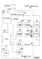
- Figure 2 is a block diagram of the central control unit of Figure 1.
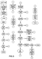
- FIG 3 is a flow chart of the processing utilized by the central control unit of Figure 1.
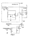
- Figure 4 is a schematic of the central transmitter of Figure 1.
- Figure 5 is a block diagram of an alarm system utilizing reduced power supervisory message transmission of the second aspect of the present invention.
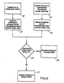
- Figure 6 is a flowchart of a method employed by the alarm sensor transmitter of Figure 5 to reduce transmission power of supervisory messages.
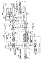
- FIGS 7A and 7B are block diagrams of an alarm sensor transmitter of the alarm system of Figure 5.
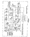
- Figure 8 is a schematic representation of an alternative embodiment of an oscillator function and an RF amplifier modulator function of Figures 7A and 7B that perform the reduced power supervisory message transmission of the second aspect of the present invention.
- Figure 9 is a schematic representation of a second embodiment of the RF amplifier modulator function of Figure 6.
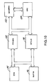
- Figure 10 is a block diagram illustrating functional blocks of an alternate embodiment of a message and CRC generator block of Figures 7A and 7B.
- Figure 1 shows a typical alarm system 5 including a central control unit 10 comprising a central system controller 70, a central receiver 90 and a central transmitter 80.
- the alarm system 5 also comprises a plurality of alarm devices 60, which refer generically to any or all of various types of alarm detection devices such as glass break detectors, door opening detectors, etc.
- the alarm system 5 also comprises a user interface device in the form of a wall mounted keypad 40, which maybe wired to the central receiver and the central transmitter.
- the wall mounted keypad 40 may also be wireless, such as an ADEMCO 5827BD, transmitting to the central transmitter and receiving from the central receiver via RF transmission.
- the wall mounted keypad (wired or wireless) allows the user to input system options by selecting specific user codes, and view system status through visual and audio means.
- the system also may include a user interface device in the form of a hand-held wireless keypad 50, such as the ADEMCO 5804BD, which allows the user to arm or disarm the alarm system 5, trigger an alarm, determine alarm system status, and display status through visual and audio indicators.
- the alarm system 5 also includes a wireless remote siren 20 and a remote dialer 30.
- the central receiver 90 receives Alarm Activation Signals from the alarm device 60 or the hand-held wireless keypad 50(e.g. a panic signal).
- the central system controller 70 analyzes the Alarm Activation Signals and determines if an alarm condition truly exists. If an alarm condition does exist, the central transmitter 80 broadcasts an Alarm Received Message to the wireless remote siren 20, wireless dialer 30, hand held wireless keypad 50 and wall mounted keypad 40.
- the receiver 90 receives status requests, install mode commands and other commands from the wall mounted keypad 40 which is part of the invention herein.
- the transmitter 80 transmits status messages when the receiver receives a status request. Details regarding the protocol of the transmission of commands and status between the wired or wireless devices and the central control unit are already well known to someone skilled in the art.
- the installer typically mounts the central control unit 10 in a remote hidden location because it is important to limit access from an intruder and it is rather large and unsightly. He then installs the wall mounted keypad 40, on the wall of the building by an entrance.
- a site ID is embedded in each device's transmission.
- the wall mounted keypad 40 requests the site ID to be transmitted from the central control unit 10. If the cover of the central control unit 10 has been removed (a safety feature which allows the site ID to be sent only during installation) the site ID is transmitted by the central control unit 10.
- the site ID is programmed into EEPROM in the central control unit 10 at the factory.
- the wall mounted keypad 40 receives a device address, which is necessary for communication with the central control unit 10.
- the messages to and from the central control unit 10 also contain this address allowing the central control unit 10 to decode which alarm device sent the message.
- the details of how a device learns the site ID and device address are well known in the art and are not described here.
- the installer enters a command, such as a status request, into the wall mounted keypad 40 and checks to see that the wall mounted keypad 40 displays the status. This insures communication between the wall mounted keypad 40 and the central control unit 10.
- the installer then enters the install command into the wall mounted keypad 40 or activates install mode switch S1 to indicate to the central system controller 10 that a Power Control Signal 120 should be at a logic level 0.
- the Power Control Signal is connected via wires from the central system controller 70 to both the central receiver 90 and the central transmitter 80 and causes both the central receiver 90 and the central transmitter 80 to go into a reduced power install mode.
- the reduced power install mode causes the central receiver 90 to receive signals at a power level of approximately 12dB lower than its normal level by reducing its sensitivity and the central transmitter 80 to transmit messages at a power level also of approximately 12dB lower than its normal level.
- the installer will recheck its communication with the central control unit 10 by entering a status request user code at the wall mounted keypad 40, which is transmitted to the central receiver 90. If the status request message is received by the receiver, now at low power, the central transmitter 80 will transmit a status message to the wall mounted keypad 40 also at low power. The installer will then check to see if the status message is received and displayed by the wall mounted keypad 40. If not the installer relocates the wall mounted keypad 40 and rechecks its communication in the same way.
- the installer then mounts a wireless device, such as remote siren 20, on the outside of the building (or inside in a basement).
- a wireless device such as remote siren 20
- the site ID and the device address are learned by the wireless device in the same manner as the wall mounted keypad.
- a convenient way to test for adequate signal margin between the central control unit 10 and the wireless device is to simulate the presence of an alarm condition and check to see if the wireless device takes appropriate action.
- the installer activates switch S2 which causes the central system controller 70 to generate an alarm received message.
- the alarm received message is transmitted by the central transmitter 80 at a reduced power to the remote siren 20. If the remote siren 20 receives the message and performs its function (i.e. sounds an audible tone), the installer knows the remote siren 20 has been installed with adequate signal margin.
- the installer will relocate the remote siren 20 (i.e. move it closer) and retest by activating alarm switch S2. The process can be repeated until the siren is successfully heard, thus ensuring an adequate signal margin during normal operation mode. Finally, the installer will turn the remote siren 20 off using key codes at the wall mounted keypad 40.
- the installer locates the proper position of the first wireless device, i.e. the remote dialer 30, and/or the hand held wireless keypad 50.
- the processes would bc the same for each wireless device except that the installer would be looking for different outputs.
- the remote dialer's 30 output would be telephone transmission of alarm information to a security station and the hand held wireless keypad's 50 output would also be display of an alarm code and/or sounding of an audible alarm signal.
- the installer then installs the alarm devices 60 and checks the entire system operation by raising an alarm at the device 60, such as by opening a window.
- the alarm device 60 transmits the Alarm Activation Signal, which is received at reduced power by the central receiver 90.
- the input data from the central receiver is processed by the central system controller.
- the central system controller 70 sends output data 140 to the central transmitter 80.
- the central transmitter 80 broadcasts the Alarm Received Message at reduced power to the wireless devices.
- the wireless devices take appropriate action and indicate by visual or audible means that they have received an Alarm Received Message. At this point the installer knows that there is adequate signal margin in both the up and down links.
- the installer then exits the install mode via a keyed command from the wall mounted keypad 40.
- the central system controller 70 sets the Power Control signal 120 to a logic level 1. This causes the central receiver 90 to receive at normal power and the central transmitter 80 to transmit at normal power. Thus all messages are conveyed during normal operation at a signal margin above that which was used during installation.
- the significance of the present invention is the ability to reduce output power of the central transmitter 80 during the alarm system installation to insure that adequate signal margin exists in normal operation mode. It will be apparent to those skilled in the art that the transmitted messages may be formatted in many different ways, and that the invention is not dependent on a particular format. Also the design of the remote siren 20, the remote dialer 30, the hand held wireless keypad 50, the wall mounted keypad 40, and the alarm devices 60 are well know in the art and do not need to be described.
- the interrupt register 305 receives four interrupts, data ready, install mode, alarm, and normal mode.
- the data ready interrupt signals the processor 200 to read input data from the receiver register 225.
- the install mode switch S1 interrupt signals the processor 200 go into install mode.
- the alarm switch S2 interrupt signals the processor 200 to output an alarm received message through the transmitter register 230.
- normal mode interrupt from Install Timer 300 signals the processor 200 to go into normal mode from install mode.
- the status register 220 storage includes the status of the wireless devices, the status of enable alarm, and the mode, normal or install.
- the control register 210 controls the input and output power level of the receiver 90 and the transmitter 80, via the power control signal 120. This signal also initiates the install timer 300.
- Figure 3 shows the flow chart of the central system controller 70.
- the processor 200 in figure 2 performs a typical start up routine such as loading the processor program, resetting hardware and loading the control register. This is well known to those skilled in the art.
- the processor 200 also transmits a status request to the wireless devices and goes into an idle mode to wait for an interrupt.
- the processor 200 performs an interrupt routine which includes reading the interrupt register 305. If the processor 200 determines the interrupt was from the install mode Switch S1, it writes to the control register 210 changing the logic level of the Power Control signal 120 from a logic 1 to a logic 0. If the processor 200 determines the interrupt was from the alarm switch S2, it transmits an alarm received message to the wireless devices via transmitter register 230.
- the processor 200 determines the interrupt was from the timer, it writes to the control register 210 changing the logic level of the Power Control signal 120 from a logic 0 to a logic 1. Lastly, if the processor 200 determines the interrupt was from the data ready interrupt, it reads the data from the receiver register 225. The input data is decoded, and the processor 200 determines if there should be a change in the options stored by the status register 220, if the alarm mode should be enabled or disabled, if the transmitter and receiver should be in the reduced power installation mode or the normal power mode, or if the input data is an alarm signal. If the input data is an alarm signal, the status register 220 is read to determine if the alarm mode is enabled. If it is not enabled, the transmission is ignored.
- the processor 200 transmits an alarm received message to the wireless devices via the transmitter register 230. If the input data is erroneous an error is stored in the status register 220, and a message is transmitted to the wireless devices. The status register 220 is also updated after any changes have been performed to the alarm system and status messages are sent to the devices. The details of each processing step would be well known to someone skilled in the art. This flow chart does not include all the processes necessary for an alarm systems total operation, only processes pertinent to the present invention.
- FIG. 4 shows a detailed implementation of the power control feature of the central transmitter 80.
- the central transmitter 80 output, from antenna 400, is controlled by power amplifier Q3. Decreased current through Q3 causes decreased output transmission power.
- the current through Q3 is controlled by three sources: current source 440, data signal 430 and RF signal 410.
- the current source 440 which is equal to the current through R1, is controlled by the Power Control signal 120.
- R2 When the Power Control signal 120 is at a logic level 1, R2 is active and the current through R1 is increased.
- R2 is switched out of the circuit via T1, and the current through R1 is decreased.
- the data signal 430 modulates Q3 according to the logic level of Data Output signal 140, and the RF signal 410 is amplified by Q3.
- the RF is from RF oscillator 420, which is enabled by the Osc Enable signal 130. RF modulation of data signals and the electrical components of this circuit are well known to one skilled in the art.
- Fig. 5 illustrates a block diagram of an alarm system 11, which comprises a central receiver control unit 12, a plurality of alarm sensor transmitters 14, and a console 16.
- the central receiver control unit 12 is in communication with the plurality of alarm sensor transmitter 14, each of which comprise an alarm sensor and a transmitter.
- the alarm sensor transmitters 14 are well known in the art and comprise, for example, motion detectors, fire or smoke sensors, glass breakage detectors, door or window entry sensors, and similar sensors.
- the alarm system 11 operates in a wireless fashion by electromagnetic wave transmission (e.g., radio frequency waves) between the alarm sensor transmitters 14 and the central receiver control unit 12.
- each alarm sensor transmitter 14 The transmitters within each alarm sensor transmitter 14 are also well known in the art, and transmit supervisory and alarm messages which modulate a radio frequency signal (e.g., 345 MHz).
- the modulated radio frequency signal is received, processed and decoded by the central receiver control unit 12, enabling the central receiver control unit 12 access to be provided with the information contained within the supervisory or alarm message and act accordingly (e.g., by sounding an alarm speaker, dialing the police or fire station, etc.).
- a radio frequency signal e.g. 345 MHz
- the modulated radio frequency signal is received, processed and decoded by the central receiver control unit 12, enabling the central receiver control unit 12 access to be provided with the information contained within the supervisory or alarm message and act accordingly (e.g., by sounding an alarm speaker, dialing the police or fire station, etc.).
- wireless alarm systems may be found in U.S. Patent No. 4,754,261 to Marino, which is owned by the assignee of the present invention and is hereby incorporated by
- the alarm sensor transmitters 14 are designed to transmit supervisory messages and alarm messages indicating the status of the alarm sensors in accordance with protocols well known in the art.
- the supervisory message functions to provide a periodic and continuous Built-in-Test (BIT) capability which ensures that communication between each alarm sensor transmitter 14 and the central receiver control unit 12 is operative. Since it is possible in this type of system that an alarm sensor transmitter 14 may only transmit an alarm signal during a health, safety or security emergency (e.g., when a window associated with the sensor is broken), it is imperative that the alarm system 11 maintain a periodic method of ensuring the communication link between each of the alarm sensor transmitters 14 and the central receiver control unit 12 is operative so that potential problems may be attended to promptly at non-critical moments.
- BIT Built-in-Test
- Fig. 6 illustrates a method utilized by the alarm sensor transmitters 14 to determine when to reduce the transmitted power (i.e. upon termination of a supervision signal).
- a supervisory period termination signal will be generated which will in turn prompt the generation of the supervisory message in step 21.
- a transmission power control signal will simultaneously be set high (i.e. logic 1) indicating that the supervisory message should be transmitted at a reduced power level.
- a non-supervisory message (an alarm message) will be generated in step 24 and the transmission power control signal will be set to low (logic 0).
- the sense of the transmission power control signal is arbitrary, as long as it is defined in advance and the intended tasks take place accordingly in response to a given sense.
- the transmitter will examine the transmission power control signal in decision 26 and if it is high (indicating that the message is a supervisory message), then the transmitter will transmit the message at a predetermined reduced power level in step 28. However, if the transmission power control signal is low (indicating that the message is a non-supervisory message), then the transmitter will transmit the message at a predetermined normal or maximum power level in step 31.
- Figs. 7A and 7B illustrate detailed top-level block diagrams of some of the essential functions of the alarm sensor transmitter 14 comprising a supervisory period timer function 32, an oscillator function 34, a message generation function 36, a phase locked loop function 38, a radio frequency (RF) amplifier modulator function 41, and a DC supply control 42.
- the supervisory period timer 32 comprises a wake-up oscillator and counter 44 that runs continuously and counts the passage of time. Whenever a period of time corresponding to the supervisory period has elapsed, then the wake-up oscillator and counter 44 will output a supervisory period termination signal 46 to the message generation function 36.
- the length of time corresponding to the supervisory period is fixed by a time constant 48 that may comprise a circuit comprising resistors and capacitors, a crystal, a resonator or other alternative components well known in the art.
- the length of the supervisory period is typically on the order of one hour or less according to applicable national regulations.
- the supervisory message Upon receipt of the supervisory period termination signal by the message generation function 36, the supervisory message is synthesized from a unique identification word 48 stored in non-volatile memory, a Cyclic Redundancy Check (CRC) sequence, and a status byte formed from various external status inputs comprising alarm sensor inputs 51.
- the unique identification word 48 identifies the source of the supervisory message as coming from a particular alarm sensor transmitter 14.
- the CRC sequence is provided for error detection and is well known in the art (see for example w. Stallings Data and Computer Communications 101-110 (1985), which is hereby incorporated by reference).
- the transmission power control signal 52 transitions to a high state that is then used to control the transmission power established in the RF amplifier modulator function 41.
- a non-supervisory message an alarm message
- the transmission power control 52 signal would maintain or transition to a low state which will cause the RF amplifier modulator function 41 to transmit the non-supervisory message at the predetermined normal or maximum power level.
- the phase detector 62 comprises a device that produces an output voltage proportional to the phase difference between an phase detection clock 66 and a divider output signal 68.
- the VCO 58 is a circuit that produces a VCO output signal 71 whose frequency is proportional to the loop filter voltage at node A.
- the divider 64 is a device that produces a divider output signal 68 whose frequency is an integer division of the VCO output signal 71.
- the loop filter 72 is a circuit that is used to shape the overall response of the phase locked loop function 38.
- the loop filter illustrated in Figs. 3 and 3B is an active loop filter comprising an operational amplifier PAl and additional discrete resistors and capacitors.
- the RF amplifier modulator function 41 modulates the VCO output signal 71 with the message data signal 76 and outputs the resulting modulated signal to an antenna.
- On-Off Keying would be utilized, which essentially-varies the amplitude of the carrier between zero and a predetermined amplitude in response to the message data signal 76.
- alternative methods of modulation such as Frequency-Shift Keying and Phase-Shift Keying could be employed while still remaining within the scope of the present invention.
- the oscillator function 34 provides the message generation function 36 with a data clock via a data clock buffer 78 and a crystal occillator 84 which is used for a general system clock as well as synchronization of the output data stream on the message data signal 76.
- the oscillator function 34 also provides the phase locked loop function 38 with the phase detection clock 66 after a frequency division function 81 controlled by a frequency division control signal 82 from the message generator function 36.
- the oscillator output reference clock is used as a phase reference which the phase locked loop function 38 bases the phase of the VCO output signal 71 on.
- the DC supply control 42 comprises a power-on reset function 84, and a battery monitor function 86.
- the power-on reset function 84 provides a stable reset signal to the message generation function 36 in order to permit the orderly initialization of registers, clocks and voltage levels upon initialization of registers, clocks and voltage levels upon applying power to various circuits of the alarm sensor transmitter 14.
- the battery monitor function 86 ensures that the voltage of a battery used as the primary power source meets operating specifications and if not informs the message generation function 36 of that fact via the status portion of the message or equivalent means well known in the art.
- the oscillator function 34 provides an RF signal 91 (similar to the VCO output signal 71 of Figs. 7A and 7B) which is enabled by an oscillator enable signal 92 and modulated by the message data signal 76 in a substantially similar manner as described with respect to Figs. 7A and 7B.
- alarm non-supervisory
- all supervisory messages are subject to a reduction in transmitter effective radiated power thus ensuring adequate system margin.
- Fig. 10 illustrates a hierarchical functional block diagram of an alternate embodiment of the message and CRC generator block 36 of Figs. 7A and 7B.
- Each of the blocks represents additional circuitry (not shown) that carries out the particular functions of that block. This additional circuitry would typically take the form of discrete analog and digital components, primitives within an ASIC or equivalent means well known in the art.
- An EDG block 94 is responsible for assembling status bits in order to construct the alarm status message.
- a SUPTIM block 96 monitors the output from the supervisory period timer 32 shown in Figs. 7A and 7B.
- a TETCLK block 98 provides clock, timing, and control signals for the message and CRC generator.
- a PREAMB block 100 assembles the preamble of the various supervisory and non-supervisory messages generated by the message and CRC generator.
- a MAINREG block 102 provides the identification word unique to each alarm sensor transmitter and embedded in the supervisory message.
- a CRC block 104 provides error checking on the messages.
- the method of the present invention does not rely for its success on multiple supervisory or alarm messages to be sent at each alarm event, nor is this method adversely effected by multiple transmissions. In addition, this method does not require a specific supervisory bit in the data transmitted.
- the embodiment described with reference to Fig. 6 may be realized in a fully integrated Application Specific Integrated Circuit (ASIC) containing each of the functions illustrated in Fig. 6. Those skilled in the art will recognize that the present invention could also be implemented using discrete circuitry with associated cost and total circuit area penalties.
- ASIC Application Specific Integrated Circuit
Abstract
Description
Claims (28)
- A method for installing an alarm system comprising the steps of:a) initiating an install mode in a central control unit,b) transmitting from a transmitter a message at a reduced power level with respect to a normal operating power level,c) receiving, at a wireless device, said reduced power message, said wireless device being relocatable with respect to said transmitter, and,d) indicating when said reduced power message is successfully received.
- The method of claim 1 further comprising the step of: when said reduced power message is not successfully received, thena) relocating said wireless device,b) transmitting from said transmitter a message at a reduced power level with respect to a normal operating power level,c) receiving, at said wireless device, said reduced power message, said wireless device being relocatable with respect to said transmitter, and,d) indicating when said reduced power message is successfully received.
- The method of claim 1 wherein the reduced power message is a reduced power alarm received message.
- The method of claim 1 wherein the reduced power message is a reduced power status message.
- The method of claim 3 wherein the step of transmitting an alarm received message is in response to a receipt of an alarm activation signal from a device.
- The method of claim 5 wherein said alarm activation signal is received by a receiver at reduced sensitivity.
- The method of claim 6 wherein the step of transmitting a reduced power status message is in response to a receipt of a status request message from a user interface device.
- The method of claim 7 wherein said status request message is received by a receiver at reduced sensitivity.
- A alarm system comprising:a) a central control unit adapted to operate in an install mode, said central control unit comprising transmission means for transmitting during said install mode a message at a reduced power level with respect to a normal operating power level, andb) a wireless device comprising:said wireless device being relocatable with respect to said transmitter means.(i) a receiver for receiving said reduced power message, and,(ii) means for indicating when said reduced power message is successfully received,
- The system of claim 9 further comprising a user interface device, said user interface device comprising input means for entering user input codes.
- The system of claim 10 wherein said user interface device is wireless and further comprises output means for sending a message from said wireless user interface device to said central control unit, and wherein said central control unit further comprises means for receiving said message from said user interface device.
- The system of claim 11 wherein said message is an install mode command which initiates said install mode in said central control unit.
- The system of claim 11 wherein said message is a status request message which initiates said central control unit to transmit a status message.
- The system of claim 9 wherein said central control unit further comprises means for receiving an alarm activation signal, wherein said alarm activation signal initiates a transmission of an alarm received message from said transmission means to said wireless device receiver.
- The system of claim 9 wherein receiving means is adapted to receive an alarm activation signal at reduced sensitivity during said install mode.
- The system of claim 13 wherein receiving means is adapted to receive status request messages at reduced sensitivity during said install mode.
- The system of claim 9 wherein said wireless device is a wireless hand-held user interface device, and wherein said means for indicating when said reduced power message is successfully received is a status output means.
- The system of claim 9 wherein said central control unit comprises a processor, said processor being adapted to output a control signal to said transmission means upon initiation of said install mode to reduce said transmission means output power level.
- The system of claim 18 wherein said central control unit further comprises means for receiving an alarm activation signal, wherein said alarm activation signal initiates a transmission of an alarm received message from said transmission means to said wireless device receiver, and wherein said wireless hand-held user interface device is adapted to transmit said alarm activation signal.
- A method for periodically self-testing a communications path in wireless alarm systems, which comprises:timing a supervisory period to provide a delay between transmissions of supervisory messages;generating a supervisory message;generating a transmission power control signal comprising one of at least two states upon termination of said supervisory period; andtransmitting said supervisory message at a reduced power level as indicated by said state of said transmission power control signal.
- The method of claim 20, further comprising:generating an alarm status message in response to receipt of an alarm status signal from an alarm sensor;generating said transmission power control signal in response to receipt of said alarm status signal from said alarm sensor; andtransmitting said alarm status message at a normal power level as indicated by said state of said transmission power control signal.
- An apparatus for periodically self-testing a communications path in wireless alarm systems, which comprises:supervisory period timing means for timing a duration of a supervisory period existing between transmissions of supervisory messages;means for outputting a supervisory period termination signal upon termination of said supervisory period;message generation means for generating said Supervisory message and a transmission power control signal, said transmission power control signal comprising one of at least two states; andtransmission means for transmitting said supervisory message at a predetermined reduced power level in response to a first state of said transmission power control signal.
- The apparatus of claim 22, wherein said message generation means further comprises means for generating an alarm status message and said transmission power control signal in response to receipt of an alarm status signal from an alarm sensor.
- The apparatus of claim 23, wherein said transmission means transmits said alarm status message at a predetermined normal power level in response to said state of said transmission power control signal.
- The apparatus of claim 22, further comprising oscillator means for outputting a data clock signal which synchronizes said message generation means and a phase detection clock signal which synchronizes said transmission means.
- The apparatus of claim 7, further comprising phase locking means for substantially maintaining correlation between a phase of a transmission signal with a phase of said phase detection signal.
- The apparatus of claim 26, wherein said transmission means modulates said transmission signal with said generated supervisory message and outputs said modulated transmission signal.
- An alarm sensor transmitter for use in a wireless alarm system, which comprises:a supervisory period timer which times a duration of a supervisory period existing between transmissions of supervisory messages and outputs a supervisory period termination signal upon termination of said supervisory period;a message generator which generates said supervisory message and a transmission power control signal in response to said supervisory period termination signal, said transmission power control signal comprising at least two states, said message generator generating an alarm status message and said transmission power control signal in response to receipt of an alarm status signal from an alarm sensor;a radio frequency transmitter which transmits said supervisory message at a predetermined reduced power level in response to said state of said transmission power control signal and transmits said alarm status message at a predetermined normal power level in response to said state of said transmission power control signal, said radio frequency transmitter modulating said transmission signal with said generated supervisory message and said alarm status message and outputting said modulated transmission signal;an oscillator which outputs a data clock signal for synchronizing said message generator and a phase detection clock signal for synchronizing said radio frequency transmitter, said data clock signal and said phase detection clock signal being substantially in phase with each other; anda phase lock loop circuit which substantially maintains correlation between a phase of said transmission signal and a phase of said phase detection clock signal.
Applications Claiming Priority (4)
| Application Number | Priority Date | Filing Date | Title |
|---|---|---|---|
| US4450997P | 1997-04-21 | 1997-04-21 | |
| US4373797P | 1997-04-21 | 1997-04-21 | |
| US44509P | 1997-04-21 | ||
| US43737P | 1997-04-21 |
Publications (3)
| Publication Number | Publication Date |
|---|---|
| EP0874341A2 true EP0874341A2 (en) | 1998-10-28 |
| EP0874341A3 EP0874341A3 (en) | 1999-08-04 |
| EP0874341B1 EP0874341B1 (en) | 2003-08-27 |
Family
ID=26720776
Family Applications (1)
| Application Number | Title | Priority Date | Filing Date |
|---|---|---|---|
| EP98201230A Expired - Lifetime EP0874341B1 (en) | 1997-04-21 | 1998-04-17 | Reduced power installation and supervision of wireless security system devices |
Country Status (3)
| Country | Link |
|---|---|
| EP (1) | EP0874341B1 (en) |
| DE (1) | DE69817435T2 (en) |
| ES (1) | ES2201403T3 (en) |
Cited By (6)
| Publication number | Priority date | Publication date | Assignee | Title |
|---|---|---|---|---|
| WO2000077758A1 (en) * | 1999-06-15 | 2000-12-21 | Carduck Annette | Mobile feedback detector |
| US6507277B2 (en) | 2000-10-10 | 2003-01-14 | Job Lizenz Gmbh & Co. Kg | Danger signalling system |
| WO2005038738A1 (en) * | 2003-10-15 | 2005-04-28 | Eaton Corporation | Home automation system including plurality of wireless sensors and a portable fob with a display |
| US7483403B2 (en) | 2002-01-10 | 2009-01-27 | Robert Bosch Gmbh | Protocol for reliable, self-organizing, low-power wireless network for security and building automation systems |
| EP2503527A1 (en) | 2011-03-23 | 2012-09-26 | Hekatron Vertriebs GmbH | Communication system, in particular for alarms and method for its operation |
| WO2019015386A1 (en) * | 2017-07-19 | 2019-01-24 | 西安中兴新软件有限责任公司 | Power consumption adjusting method and terminal |
Citations (4)
| Publication number | Priority date | Publication date | Assignee | Title |
|---|---|---|---|---|
| US4754261A (en) * | 1987-03-30 | 1988-06-28 | Pittway Corporation | Security system |
| WO1991014244A1 (en) * | 1990-03-03 | 1991-09-19 | Cedardell Limited | Communications system |
| US5461365A (en) * | 1994-10-27 | 1995-10-24 | Schlager; Dan | Multi-hazard alarm system using selectable power-level transmission and localization |
| EP0733988A2 (en) * | 1995-03-22 | 1996-09-25 | International Computers Limited | Electronic identification system |
-
1998
- 1998-04-17 DE DE69817435T patent/DE69817435T2/en not_active Expired - Lifetime
- 1998-04-17 EP EP98201230A patent/EP0874341B1/en not_active Expired - Lifetime
- 1998-04-17 ES ES98201230T patent/ES2201403T3/en not_active Expired - Lifetime
Patent Citations (4)
| Publication number | Priority date | Publication date | Assignee | Title |
|---|---|---|---|---|
| US4754261A (en) * | 1987-03-30 | 1988-06-28 | Pittway Corporation | Security system |
| WO1991014244A1 (en) * | 1990-03-03 | 1991-09-19 | Cedardell Limited | Communications system |
| US5461365A (en) * | 1994-10-27 | 1995-10-24 | Schlager; Dan | Multi-hazard alarm system using selectable power-level transmission and localization |
| EP0733988A2 (en) * | 1995-03-22 | 1996-09-25 | International Computers Limited | Electronic identification system |
Cited By (9)
| Publication number | Priority date | Publication date | Assignee | Title |
|---|---|---|---|---|
| WO2000077758A1 (en) * | 1999-06-15 | 2000-12-21 | Carduck Annette | Mobile feedback detector |
| US6507277B2 (en) | 2000-10-10 | 2003-01-14 | Job Lizenz Gmbh & Co. Kg | Danger signalling system |
| US7483403B2 (en) | 2002-01-10 | 2009-01-27 | Robert Bosch Gmbh | Protocol for reliable, self-organizing, low-power wireless network for security and building automation systems |
| US8194571B2 (en) | 2002-01-10 | 2012-06-05 | Robert Bosch Gmbh | Protocol for reliable, self-organizing, low-power wireless network for security and building automation systems |
| WO2005038738A1 (en) * | 2003-10-15 | 2005-04-28 | Eaton Corporation | Home automation system including plurality of wireless sensors and a portable fob with a display |
| AU2004282662B2 (en) * | 2003-10-15 | 2010-05-20 | Eaton Corporation | Home automation system including plurality of wireless sensors and a portable fob with a display |
| EP2503527A1 (en) | 2011-03-23 | 2012-09-26 | Hekatron Vertriebs GmbH | Communication system, in particular for alarms and method for its operation |
| DE102011014889A1 (en) | 2011-03-23 | 2012-09-27 | Hekatron Vertriebs Gmbh | Communication system, in particular for hazard alarms and methods for its operation |
| WO2019015386A1 (en) * | 2017-07-19 | 2019-01-24 | 西安中兴新软件有限责任公司 | Power consumption adjusting method and terminal |
Also Published As
| Publication number | Publication date |
|---|---|
| EP0874341A3 (en) | 1999-08-04 |
| ES2201403T3 (en) | 2004-03-16 |
| EP0874341B1 (en) | 2003-08-27 |
| DE69817435T2 (en) | 2004-03-11 |
| DE69817435D1 (en) | 2003-10-02 |
Similar Documents
| Publication | Publication Date | Title |
|---|---|---|
| US6288639B1 (en) | Low power installation of wireless security system devices | |
| EP1055211B1 (en) | Adaptive console for augmenting wireless capability in security systems | |
| US6980150B2 (en) | System and method for controlling home appliances | |
| US6208694B1 (en) | Reduced power supervisory message transmission in a wireless alarm system | |
| US5646593A (en) | Child proximity detector | |
| US6087933A (en) | Antenna switching for amplitude degradation during supervision and installation of wireless security systems | |
| US5077547A (en) | Non contact programming for transmitter module | |
| JP2002512739A (en) | Inventory system at random intervals | |
| US20030190906A1 (en) | Security control and communication system and method | |
| WO1994003881A1 (en) | Fire detection system | |
| AU2002245502A1 (en) | System and method for controlling home appliances | |
| US5701189A (en) | Wireless data communication system and method using an electroluminescent panel | |
| EP0874341B1 (en) | Reduced power installation and supervision of wireless security system devices | |
| JP2840367B2 (en) | Wireless alarm system | |
| JP2840344B2 (en) | Wireless alarm system | |
| JPH09158562A (en) | Locking manipulation detector | |
| JPS6146599A (en) | Emergency alarm | |
| JP3056811B2 (en) | Method of setting carrier frequency of slave station in wireless communication system | |
| JP3386534B2 (en) | Communication device | |
| KR100199775B1 (en) | An automatically electronic locking method | |
| KR100470019B1 (en) | Positioning device of hand terminal | |
| JPH06162377A (en) | Disaster prevention radio device | |
| JPS6323440A (en) | Communication system | |
| JPS607319B2 (en) | Operation notification method | |
| US6501388B1 (en) | Radio signal selective-calling receiver and method of receiving radio signals |
Legal Events
| Date | Code | Title | Description |
|---|---|---|---|
| PUAI | Public reference made under article 153(3) epc to a published international application that has entered the european phase |
Free format text: ORIGINAL CODE: 0009012 |
|
| AK | Designated contracting states |
Kind code of ref document: A2 Designated state(s): DE ES FR GB IT NL |
|
| AX | Request for extension of the european patent |
Free format text: AL;LT;LV;MK;RO;SI |
|
| PUAL | Search report despatched |
Free format text: ORIGINAL CODE: 0009013 |
|
| AK | Designated contracting states |
Kind code of ref document: A3 Designated state(s): AT BE CH CY DE DK ES FI FR GB GR IE IT LI LU MC NL PT SE |
|
| AX | Request for extension of the european patent |
Free format text: AL;LT;LV;MK;RO;SI |
|
| 17P | Request for examination filed |
Effective date: 19990913 |
|
| AKX | Designation fees paid |
Free format text: DE ES FR GB IT NL |
|
| 17Q | First examination report despatched |
Effective date: 20020612 |
|
| GRAH | Despatch of communication of intention to grant a patent |
Free format text: ORIGINAL CODE: EPIDOS IGRA |
|
| GRAS | Grant fee paid |
Free format text: ORIGINAL CODE: EPIDOSNIGR3 |
|
| GRAA | (expected) grant |
Free format text: ORIGINAL CODE: 0009210 |
|
| RAP1 | Party data changed (applicant data changed or rights of an application transferred) |
Owner name: HONEYWELL INTERNATIONAL INC. |
|
| AK | Designated contracting states |
Designated state(s): DE ES FR GB IT NL |
|
| PG25 | Lapsed in a contracting state [announced via postgrant information from national office to epo] |
Ref country code: NL Free format text: LAPSE BECAUSE OF FAILURE TO SUBMIT A TRANSLATION OF THE DESCRIPTION OR TO PAY THE FEE WITHIN THE PRESCRIBED TIME-LIMIT Effective date: 20030827 |
|
| REG | Reference to a national code |
Ref country code: GB Ref legal event code: FG4D |
|
| REF | Corresponds to: |
Ref document number: 69817435 Country of ref document: DE Date of ref document: 20031002 Kind code of ref document: P |
|
| NLV1 | Nl: lapsed or annulled due to failure to fulfill the requirements of art. 29p and 29m of the patents act | ||
| REG | Reference to a national code |
Ref country code: ES Ref legal event code: FG2A Ref document number: 2201403 Country of ref document: ES Kind code of ref document: T3 |
|
| ET | Fr: translation filed | ||
| PLBE | No opposition filed within time limit |
Free format text: ORIGINAL CODE: 0009261 |
|
| STAA | Information on the status of an ep patent application or granted ep patent |
Free format text: STATUS: NO OPPOSITION FILED WITHIN TIME LIMIT |
|
| 26N | No opposition filed |
Effective date: 20040528 |
|
| PGFP | Annual fee paid to national office [announced via postgrant information from national office to epo] |
Ref country code: IT Payment date: 20070616 Year of fee payment: 10 |
|
| PGFP | Annual fee paid to national office [announced via postgrant information from national office to epo] |
Ref country code: ES Payment date: 20080421 Year of fee payment: 11 |
|
| PG25 | Lapsed in a contracting state [announced via postgrant information from national office to epo] |
Ref country code: IT Free format text: LAPSE BECAUSE OF NON-PAYMENT OF DUE FEES Effective date: 20080417 |
|
| REG | Reference to a national code |
Ref country code: ES Ref legal event code: FD2A Effective date: 20090418 |
|
| PG25 | Lapsed in a contracting state [announced via postgrant information from national office to epo] |
Ref country code: ES Free format text: LAPSE BECAUSE OF NON-PAYMENT OF DUE FEES Effective date: 20090418 |
|
| REG | Reference to a national code |
Ref country code: FR Ref legal event code: PLFP Year of fee payment: 18 |
|
| REG | Reference to a national code |
Ref country code: FR Ref legal event code: PLFP Year of fee payment: 19 |
|
| REG | Reference to a national code |
Ref country code: FR Ref legal event code: PLFP Year of fee payment: 20 |
|
| PGFP | Annual fee paid to national office [announced via postgrant information from national office to epo] |
Ref country code: FR Payment date: 20170322 Year of fee payment: 20 |
|
| PGFP | Annual fee paid to national office [announced via postgrant information from national office to epo] |
Ref country code: GB Payment date: 20170328 Year of fee payment: 20 |
|
| PGFP | Annual fee paid to national office [announced via postgrant information from national office to epo] |
Ref country code: DE Payment date: 20170428 Year of fee payment: 20 |
|
| REG | Reference to a national code |
Ref country code: DE Ref legal event code: R071 Ref document number: 69817435 Country of ref document: DE |
|
| REG | Reference to a national code |
Ref country code: GB Ref legal event code: PE20 Expiry date: 20180416 |
|
| PG25 | Lapsed in a contracting state [announced via postgrant information from national office to epo] |
Ref country code: GB Free format text: LAPSE BECAUSE OF EXPIRATION OF PROTECTION Effective date: 20180416 |