EP0875199A1 - Organism state measuring device and relaxation instructing device - Google Patents
Organism state measuring device and relaxation instructing device Download PDFInfo
- Publication number
- EP0875199A1 EP0875199A1 EP97939174A EP97939174A EP0875199A1 EP 0875199 A1 EP0875199 A1 EP 0875199A1 EP 97939174 A EP97939174 A EP 97939174A EP 97939174 A EP97939174 A EP 97939174A EP 0875199 A1 EP0875199 A1 EP 0875199A1
- Authority
- EP
- European Patent Office
- Prior art keywords
- rate
- subject
- pulse
- body motion
- respiratory
- Prior art date
- Legal status (The legal status is an assumption and is not a legal conclusion. Google has not performed a legal analysis and makes no representation as to the accuracy of the status listed.)
- Granted
Links
Images


Classifications
-
- A—HUMAN NECESSITIES
- A61—MEDICAL OR VETERINARY SCIENCE; HYGIENE
- A61B—DIAGNOSIS; SURGERY; IDENTIFICATION
- A61B5/00—Measuring for diagnostic purposes; Identification of persons
- A61B5/72—Signal processing specially adapted for physiological signals or for diagnostic purposes
- A61B5/7203—Signal processing specially adapted for physiological signals or for diagnostic purposes for noise prevention, reduction or removal
- A61B5/7207—Signal processing specially adapted for physiological signals or for diagnostic purposes for noise prevention, reduction or removal of noise induced by motion artifacts
- A61B5/721—Signal processing specially adapted for physiological signals or for diagnostic purposes for noise prevention, reduction or removal of noise induced by motion artifacts using a separate sensor to detect motion or using motion information derived from signals other than the physiological signal to be measured
-
- A—HUMAN NECESSITIES
- A61—MEDICAL OR VETERINARY SCIENCE; HYGIENE
- A61B—DIAGNOSIS; SURGERY; IDENTIFICATION
- A61B5/00—Measuring for diagnostic purposes; Identification of persons
- A61B5/02—Detecting, measuring or recording pulse, heart rate, blood pressure or blood flow; Combined pulse/heart-rate/blood pressure determination; Evaluating a cardiovascular condition not otherwise provided for, e.g. using combinations of techniques provided for in this group with electrocardiography or electroauscultation; Heart catheters for measuring blood pressure
- A61B5/0205—Simultaneously evaluating both cardiovascular conditions and different types of body conditions, e.g. heart and respiratory condition
-
- A—HUMAN NECESSITIES
- A61—MEDICAL OR VETERINARY SCIENCE; HYGIENE
- A61B—DIAGNOSIS; SURGERY; IDENTIFICATION
- A61B5/00—Measuring for diagnostic purposes; Identification of persons
- A61B5/02—Detecting, measuring or recording pulse, heart rate, blood pressure or blood flow; Combined pulse/heart-rate/blood pressure determination; Evaluating a cardiovascular condition not otherwise provided for, e.g. using combinations of techniques provided for in this group with electrocardiography or electroauscultation; Heart catheters for measuring blood pressure
- A61B5/024—Detecting, measuring or recording pulse rate or heart rate
-
- A—HUMAN NECESSITIES
- A61—MEDICAL OR VETERINARY SCIENCE; HYGIENE
- A61B—DIAGNOSIS; SURGERY; IDENTIFICATION
- A61B5/00—Measuring for diagnostic purposes; Identification of persons
- A61B5/02—Detecting, measuring or recording pulse, heart rate, blood pressure or blood flow; Combined pulse/heart-rate/blood pressure determination; Evaluating a cardiovascular condition not otherwise provided for, e.g. using combinations of techniques provided for in this group with electrocardiography or electroauscultation; Heart catheters for measuring blood pressure
- A61B5/021—Measuring pressure in heart or blood vessels
- A61B5/022—Measuring pressure in heart or blood vessels by applying pressure to close blood vessels, e.g. against the skin; Ophthalmodynamometers
-
- A—HUMAN NECESSITIES
- A61—MEDICAL OR VETERINARY SCIENCE; HYGIENE
- A61B—DIAGNOSIS; SURGERY; IDENTIFICATION
- A61B5/00—Measuring for diagnostic purposes; Identification of persons
- A61B5/08—Detecting, measuring or recording devices for evaluating the respiratory organs
- A61B5/0816—Measuring devices for examining respiratory frequency
-
- A—HUMAN NECESSITIES
- A61—MEDICAL OR VETERINARY SCIENCE; HYGIENE
- A61B—DIAGNOSIS; SURGERY; IDENTIFICATION
- A61B5/00—Measuring for diagnostic purposes; Identification of persons
- A61B5/72—Signal processing specially adapted for physiological signals or for diagnostic purposes
- A61B5/7232—Signal processing specially adapted for physiological signals or for diagnostic purposes involving compression of the physiological signal, e.g. to extend the signal recording period
-
- A—HUMAN NECESSITIES
- A61—MEDICAL OR VETERINARY SCIENCE; HYGIENE
- A61B—DIAGNOSIS; SURGERY; IDENTIFICATION
- A61B5/00—Measuring for diagnostic purposes; Identification of persons
- A61B5/72—Signal processing specially adapted for physiological signals or for diagnostic purposes
- A61B5/7235—Details of waveform analysis
- A61B5/7239—Details of waveform analysis using differentiation including higher order derivatives
-
- A—HUMAN NECESSITIES
- A61—MEDICAL OR VETERINARY SCIENCE; HYGIENE
- A61B—DIAGNOSIS; SURGERY; IDENTIFICATION
- A61B5/00—Measuring for diagnostic purposes; Identification of persons
- A61B5/72—Signal processing specially adapted for physiological signals or for diagnostic purposes
- A61B5/7235—Details of waveform analysis
- A61B5/7253—Details of waveform analysis characterised by using transforms
- A61B5/7257—Details of waveform analysis characterised by using transforms using Fourier transforms
-
- A—HUMAN NECESSITIES
- A61—MEDICAL OR VETERINARY SCIENCE; HYGIENE
- A61B—DIAGNOSIS; SURGERY; IDENTIFICATION
- A61B5/00—Measuring for diagnostic purposes; Identification of persons
- A61B5/72—Signal processing specially adapted for physiological signals or for diagnostic purposes
- A61B5/7235—Details of waveform analysis
- A61B5/7253—Details of waveform analysis characterised by using transforms
- A61B5/726—Details of waveform analysis characterised by using transforms using Wavelet transforms
Definitions
- the present invention relates to a physiological state measuring device suitable for monitoring health, and particularly measuring the respiratory rate, during exercise.
- the present invention also concerns a relaxation guidance device which determines a subject ' s degree of relaxation during meditation or exercise based on changes in the respiratory rate calculated by the aforementioned physiological state measuring device, and then guides the subject into a relaxed state by informing the subject of the result of the determination.
- pulse rate/respiratory rate ratio may increase or decrease.
- Autonomic training also known as concentrated self-relaxation technique, is known to be helpful in promoting or restoring health by reducing tension.
- This type of training emphasizes placing the mind in a state of relaxation.
- the subject may become too focused on his efforts to relax, so that tension results instead.
- Breathing exercise has been developed as a part of autonomic training, to aid the subject in easing tension and shifting into a state of relaxation.
- the subject chants a phrase such as breath slowly " to himself repeatedly. As a result, the subject is able to enter a state of relaxation.
- the change rate of the respiratory rate is known to decrease when the mind has been placed in a relaxed such as described above.
- Typical method for measuring the respiratory rate in a sedentary subject include applying a band around the subject ' s chest or stomach, and then counting the number of expansions and contractions, or inserting a thermocouple in the subject ' s nostrils and counting the variation in the resistance value.
- employing such devices in a subject who is monitoring his daily health, or who is carrying out training would provide a considerable inconvenience.
- a frequency analysis RR interval fluctuation in an electrocardiogram at rest reveals the presence of a component corresponding to the respiratory rate. Since the pulse wave is synchronized with the electrocardiogram, a component corresponding to the respiratory rate should be also included in the frequency analysis of the fluctuation pattern of the pulse wave cycle (or the pulse wave amplitude).
- a device which measures the respiratory rate based on an electrocardiogram or pulse wave, by extracting this component.
- Japanese Patent Application Show 62-22627 discloses calculating the respiratory rate by measuring continuous pulse intervals, measuring the cycle of fluctuation in these pulse intervals, and then taking the reciprocal of the cycle of fluctuation.
- JPUA 451912 discloses a technique in which a first respiratory rate is detected based on the fluctuation in the envelope formed by the peak values of the pulse waveform or the cycle of fluctuation in the RR interval in the waveform of the electrocardiac waveform, a second respiratory rate is detected by detecting the up-and-down motion of the surface of the subject ' s trunk, and recording and displaying the lower of these two respiratory rates.
- JPUA 4136207 discloses estimating the respiratory rate based on the fluctuation cycle in the amplitude of the pulse waveform, and calculating the average value of the pulse waveform (the wave in the low frequency component). By employing data obtained during the average value trend is small, the influence from swell or noise can be reduced.
- JPA 6142082 discloses multiplying a subject ' s maximum blood pressure value and pulse rate which are successively obtained, and then calculating the respiratory rate based on the pulse cycle of the multiplied value.
- JPUB 622325 discloses a technique for determining the respiratory rate based on the cycle of fluctuation of a curved line connecting peak values in the pulse wave.
- the present inventors hypothesized that the relationships described above were maintained during exercise, i.e., that the respiratory rate could be estimated based on an electrocardiogram or pulse wave during exercise. Clinical studies were carried out to test this hypothesis. As a result, it was understood that a component corresponding to respiratory rate is present in the frequency component of the pulse wave fluctuation or the RR interval fluctuation of an electrocardiogram during exercise.
- the present invention was conceived in consideration of the above circumstances, and has its objective of the provision of a physiological state measuring device which can accurately and easily measure a subject ' s respiratory rate, particularly during exercise. It is another objective of the present invention to provide a device which extracts the respiratory component from the pulse wave, and then guides the subject based on the rate of change in the extracted component, so that the subject enters a relaxed mental state.
- the present invention was conceived in view of the above-described circumstances.
- the invention according to claim 1 is characterized in the provision of a circulatory system information detecting means for detecting information about the subject ' s circulatory system; and an extracting means for extracting a region determined according to the pulse or heart rate from among the results of frequency analysis on the detected circulatory system information, and measuring the respiratory rate of the subject based on the extracted region.
- the invention according to claim 2 is characterized in the provision of a circulatory system information detecting means for detecting information about the subject ' s circulatory system; an extracting means for extracting a region determined according to the pulse or heart rate from the among the frequency spectrums for the detected circulatory system information; and a measuring means for measuring the subject ' s respiratory rate based on the frequency spectrum in the extracted range.
- the invention according to claim 3 is characterized in that the circulatory system information is the amount of change in the cycle of the pulse wave or the level of the electrocardiogram.
- the invention according to claim 4 is characterized in that the circulatory system information is the amount of change in the amplitude value of the pulse wave or the level of the electrocardiogram.
- the invention according to claim 5 is characterized in the provision of a portable portion which is attached to the subject for detecting the circulatory system information, and a main portion designed to enable communication with the portable portion.
- the invention according to claim 6 is characterized in the provision of a body motion removing means for removing the body motion spectrum corresponding to the subject ' s body motion from the frequency spectrum extracted by the extracting means, wherein the subject ' s respiratory rate is generated based on the output from the body motion removing means.
- the invention according to claim 7 is characterized in that the body motion removing means is provided with a body motion detecting means for detecting the subject ' s body motion; a body motion spectrum detecting means for determining the body motion spectrum corresponding to the subject ' s body motion, based on the results detected by the body motion detecting means; and a body motion correcting means for removing the body motion spectrum from the frequency spectrum extracted by the extracting means.
- the invention according to claim 8 is characterized in that the body motion removing means is provided with a fundamental frequency table in which associations have been created in advance for the respiratory fundamental frequency and the body motion fundamental frequency according to the change in exercise intensity; and a frequency specifying member for referencing the fundamental frequency table and specifying the respiratory fundamental frequency and the body motion fundamental frequency from among the frequency spectrums extracted by the extracting means; wherein the respiratory rate is calculated based on the respiratory fundamental frequency specified by the frequency specifying member.
- the invention according to claim 9 is characterized in that the body motion detecting means detects acceleration of the subject ' s arms, and the body motion correcting means removes the body motion spectrum corresponding to the frequency of the acceleration from the frequency spectrum.
- the invention according to claim 10 is characterized in the provision of a warning means for providing a warning relying on the subject ' s five senses, when the measured respiratory rate is outside a specific range.
- the invention according to claim 11 is characterized in the provision of a calculating means for calculating the change rate of the respiratory rate based on the measured respiratory rate.
- the invention according to claim 12 is characterized in the provision of a communicating means for sending and receiving information including indicators of physiological state to and from an external device which is provided separately from the main body of the device.
- the invention according to claim 13 is characterized in that the communicating means is provided with a recognition information recording means in which particular recognition numbers are provided, wherein a recognition number is associated with communicated information and sent between the external device and the device main body.
- the invention according to claim 14 is characterized in that data transmission between the device main body and the external device is carried out using compressed data.
- the invention according to claim 15 is a relaxation guidance device employing the aforementioned physiological state measuring device, characterized in the provision of an indicator generating means for generating indicators showing the subject ' s degree of relaxation based on the change rate of the respiratory rate calculated by the calculating means, and a notifying means for notifying the subject of the indicator.
- the invention according to claim 16 is characterized in that the indicator generating means generates an indicator showing the subject ' s degree of relaxation based on a comparison between a threshold value and the change rate of the respiratory rate.
- the invention according to claim 17 is characterized in that the indicator generating means is provided with a pulse rate calculating means for determining pulse rate based on circulatory system information, a rate-of-change-in-pulse-rate calculating means for calculating the rate of change in the pulse rate; and a threshold value table for storing in advance threshold values which have been associated with rates of change in the pulse rate; wherein the indicator generating means references the rate of change in the pulse rate calculated by the rate-of-change-in-pulse-rate calculating means, reads out the threshold values from the threshold value table, and generates indicators showing the subject ' s degree of relaxation based on the threshold value.
- the invention according to claim 18 is provided with a communicating means which sends the change rate of the respiratory rate calculated by the calculating means, and receives the indicator generated by the indicator generating means which is provided to the external device, to and from the external device which is provided external to the main body of the device, wherein the subject is notified of the indicator by the notifying means provided to the device main body.
- FIG. 1 shows a wristwatch incorporating the device according to the first and second embodiments of the present invention, and a personal computer which carries out optical communications with the device.
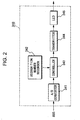
- FIG. 2 is a detailed block diagram showing the transmission device provided inside the input/output interface incorporated in the device according to the first and second embodiments of the present invention.
- FIG. 3 is a circuit diagram of the photoelectric pulse wave sensor (sensor unit 102).
- FIG. 4 shows the correspondence between waveform parameters and the waveform of a single beat in the pulse wave.
- FIG. 5 is a block diagram showing the structure of parameter extracting member 180.
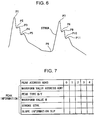
- FIG. 6 shows an example of the radius artery waveform stored in waveform memory 184.
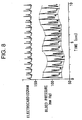
- FIG. 7 shows the memory contents of peak information memory 205.
- FIG. 8 shows the relationship between the electrocardiogram and the pulse wave.
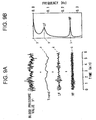
- FIG. 9 shows the fingertip plethysmogram envelope, the components making up the envelope, and the results obtained when spectral analysis is performed on the fingertip plethysmogram envelope.
- FIG. 10 shows an arrangement in which a photoelectric pulse wave sensor and a wristwatch have been combined, and the photoelectric pulse wave sensor has been attached to the base of the finger.
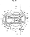
- FIG. 11 is a planar view showing the structure of the wristwatch employed in the embodiment 10 in greater detail.
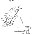
- FIG. 12 shows an arrangement in which a photoelectric pulse wave sensor and a wristwatch have been combined, and the photoelectric pulse wave sensor has been attached to the fingertip.
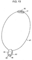
- FIG. 13 shows an arrangement in which the photoelectric pulse wave sensor has been incorporated into a necklace.
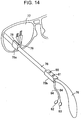
- FIG. 14 shows an arrangement in which the photoelectric pulse wave sensor has been combined with a pair of eyeglasses.
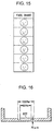
- FIG. 15 shows a face chart employed as the notifying means.
- FIG. 16 is a cross-sectional view of the wristwatch in an example in which the notifying means has been incorporated inside the watch, in the case where notification is carried out using a piezo element to create vibration.
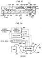
- FIG. 17 is a cross-sectional view showing the structure of micropump 501 according to the present invention.
- FIG. 18 is a block diagram showing the structure of the driving member for driving micropump 105.
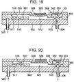
- FIG. 19 is an explanatory figure of the operation of micropump 501.
- FIG. 20 is an explanatory figure of the operation of micropump 501.
- FIG. 21 is a block diagram showing the functional structure of the first embodiment.
- FIG. 22 shows an example of the relationship between pulse wave analysis date MFD, body motion analysis date TFD and pulse wave analysis data MKD from which body motion has been removed, according to the same embodiment.
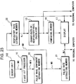
- FIG. 23 is a block diagram showing the functional structure of the third embodiment.
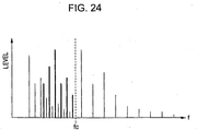
- FIG. 24 shows the relationship between pulse wave analysis data MFD and the cut-off frequency fc of the low pass filter.
- FIG. 25(a) shows pulse wave component analysis data MD
- FIG. 25(b) shows analysis data MD ' from which the pulse wave component has been removed.
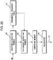
- FIG. 26 is a block diagram showing the detailed functional structure of respiratory rate extracting member 22.
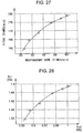
- FIG. 27 shows the results of experiments to measure the relationship between running pitch and respiratory rate.
- FIG. 28 shows the relationship between the fundamental frequency Ft1 of the body motion component and the fundamental frequency Fv1 of the respiratory rate component.
- FIG. 29 is a block diagram showing the detailed structure of the wavelet transformer.
- FIG. 30 shows an example of the pulse rate and respiratory rate during running.
- the waveform of one beat of the pulse wave has a shape as shown in FIG. 4. Blood pressure values are plotted along the vertical axis in this figure, with time noted along the horizontal axis. The following is defined as a waveform parameter for specifying the shape of this type of pulse waveform.
- peak information information is extracted that is related to each of the aforementioned maximum and minimum points. This information is referred to as peak information " .
- the waveform extraction recording member described below extracts the peak information from the pulse waveforms which have been taken up. Since the details of the peak information are related to the structure and operation of the waveform extraction recording member, a more detailed description thereof will be made when the structure of the circuit is explained.
- FIG. 3 shows the structure of sensor unit 102.
- 32 is a blue light emitting diode.
- Photo sensor 33 is formed from a phototransistor or the like.
- a light emitting diode that uses near infrared light, which has excellent transmission properties with respect to the human body, as a photoelectric pulse wave sensor.
- a blue light emitting diode is employed in this embodiment.
- the wavelength of light emitting diode 32 may be optionally selected, provided that absorption by hemoglobin is not impaired.
- Light irradiated from light emitting diode 32 is absorbed by hemoglobin in the red blood cells inside the vessels directly under the surface of the skin which is in contact with sensor unit 102. The amount of light reflected back by the tissue under the skin will vary. This reflected light is received by light sensor 33, so that a pulse wave detection signal M is received as the result of photoelectric conversion.
- this pulse wave sensor When this pulse wave sensor is incorporated in a battery-operated wristwatch, for example, it is preferable to drive the battery source of sensor unit 102 only when pulse wave measurements must be made. Thus, power consumption can be reduced.
- a switch such as indicated by symbol SW in FIG. 3 is provided along the line supplying the power source to the pulse wave sensor.
- a switch drive circuit not shown, switches each switch on or off, to supply an intermittent electric source to the sensors, etc.
- switch SW is in the off position, and an electric source is not supplied to sensor unit 102.
- switch SW is turned to the ON position, thereby supplying an electric source to sensor unit 102.
- the physiological state measuring device comprises a personal computer, and a wristwatch worn by the subject.
- the personal computer is made up of a device main body 330, display 331, key board 332, printer 333, and the like, and, with the exception of the following points, is an ordinary personal computer. Accordingly, a detailed description of its internal structure will be omitted.
- device main body 330 internally houses a transmission controller and a receiving controller, which are not shown in the figures, for sending and receiving data by means of optical signals.
- the transmission controller is provided with LED 334 for sending optical signals
- the receiving controller is provided with a phototransistor 335 for receiving optical signals.
- LED 334 and photo transistor 335 employ near infrared (having a central wavelength of 940 nm, for example), and carry out optical communications via a visible light cutting filter 336 for blocking visible light, and through a communications window 337 used for optical communications which is provided to the front surface of device main body 330.
- near infrared having a central wavelength of 940 nm, for example
- the wristwatch in FIG. 10 is formed of a device main body 100 which has the wristwatch structure, a cable 101 attached to device main body 100, and a sensor unit 102 provided to the end of cable 101.
- a wrist band 103 is provided to device main body 100 and is wrapped around the arm from the 12 o ' clock position, and fixed in place at the 6 o'clock position.
- This device main body 100 is designed to be freely detachable from the arm of the user by means of wrist band 103.
- sensor unit 102 Light to sensor unit 102 is blocked by a band 104 for fixing the sensor in place, with sensor unit 102 attached between the base and the second joint of the index finger.
- sensor unit 102 When sensor unit 102 is attached to the base of the finger in this way, cable 101 can be made short, so that it does not present a hindrance to the user during exercise, for example. Additionally, it is known that when the temperature distribution from the palm to the tip of the finger is measured, the temperature at the tip of the finger drops markedly in the case where the temperature of the surrounding environment is low, whereas the temperature at the base of the finger falls comparatively little. Accordingly, if sensor unit 102 is attached to the base of the finger, accurate measurements are possible, even in the case where exercising outdoors during cold weather.
- a connector 105 is provided at the 6 o ' clock position on the face of the wristwatch.
- a connector piece 106 which is provided to the end of cable 101, is releasabley attached to connector 105. By releasing connector piece 106 from connector 105, the device may be used as an ordinary wristwatch or stopwatch. Also, in order to protect connector 105, a specific connector cover is attached when cable 101 and sensor unit 102 are released from connector 105. With the exception of an electrode component, this connector cover may be made of parts formed in the same way as connector piece 106.
- connector 105 is disposed toward the subject, facilitating its manipulation.
- connector 105 does not extend out from device main body 100 in the 3 o ' clock position, the subject can freely move his wrist during exercise. Thus, even if the subject falls during exercise, the back of the hand will not impact connector 105.
- FIG. 11 shows the device main body 100 of this embodiment in detail, with cable 101 and wristband 103 detached.
- parts which are equivalent to those shown in FIG. 10 have been assigned the same numeric symbol and an explanation thereof has been omitted.
- device main body 100 is provided with a watch case 107 made of a resin.
- a liquid crystal display 108 is provided to the face of watch case 107 which displays in digital form the current time and date, as well as pulse wave information such as pulse and respiratory rates and the like.
- LCD device 108 is comprised of first, second, and third segment display regions 108-1, 108-2, and 108-3, respectively, and a dot display region 108-D.
- First segment display region 108-1 is positioned at the upper left area of the display panel;
- second segment display region 108-2 is positioned at the upper right area of the display panel;
- third segment display region 108-3 is positioned at the lower right area of the display panel; and dot display region 108-D is positioned at the lower left area of the display panel.
- the date, day of the week and current time are displayed in first segment region 108-1, while the passage of time when carrying out various time measurements is displayed in second segment region 108-2.
- Various measured values obtained during measurement of the pulse wave are displayed in third segment region 108-3.
- various information can be graphically displayed in dot display region 108-D, in addition to a variety of other displays such as a mode display, which indicates which mode the device is in at a particular time, pulse waveform display, bar graph display, respiratory rate display, display of the change rate of the respiratory rate, or the like.
- mode refers to a variety of modes such as a mode for setting the time and date, a mode for using the device as a stopwatch, and a mode for operating the device as a pulse wave analysis device or a diagnostic device.
- a controller 109 for carrying out signal processing for display on LCD device 108 is housed inside watch case 107.
- Controller 109 may be a one chip microcomputer or a regular microprocessor such as a CPU (central processing unit), RAM (random access memory), ROM (read-only memory) or the like.
- Controller 109 includes a watch circuit for carrying out watch functions.
- an ordinary clock time display may be used for LCD device 108, however, live time or split time displays for use when the device is operated as a stop watch are also possible.
- Button switches 111 ⁇ 117 are provided to the outer periphery and surface of watch case 107. An example of the functions of these button switches follows, however, these functions will differ depending on the device which is incorporated with the wristwatch.
- button switch 111 which is at the 2 o'clock position on the wristwatch, is pressed, an alarm is set to sound one hour thereafter.
- Button switch 112 which is at the 4 o'clock position on the wristwatch, is provided for directing switching between the device ' s various modes.
- Button switch 114 which is at the 8 o'clock position on the wristwatch, switches between the various graphic displays which are to be displayed on dot display region 108-D.
- time and date display i.e., time displayed in seconds/minutes/hours, 12 or 24 hour display, year/month, date, etc.
- time and date correction mode By pressing button switch 115, the form of time and date display (i.e., time displayed in seconds/minutes/hours, 12 or 24 hour display, year/month, date, etc.) can be switched in the day and date correction mode.
- Button switch 116 which is positioned below LCD display 108, can be used when correcting time or date, by decreasing the setting by one. Additionally, when timing a lap, button switch 116 can be used as a switch for informing controller 109 of the completion each lap.
- Button switch 117 which is positioned above LCD 108, is employed for indicating the initiation or termination of operation of the pulse wave analysis or diagnostic device. In addition to being used to increase the time and date settings by one, button switch 117 can also be used to indicate the initiation or termination of a variety of time elapse measurements.
- a button-shaped battery 118 is housed in watch case 107 and serves as a power source for the device.
- Cable 101 shown in FIG. 10 supplies electric power from battery 118 to sensor unit 102, and sends the detection results from sensor unit 102 to controller 109.
- a horizontally long watch case 107 is employed which is longer in the horizontal, (i.e., 3 o'clock to 9 o'clock) direction, than in the vertical (i.e., 6 o'clock to 12 o'clock) direction.
- wrist band 103 is connected to a watch case 107 at a position shifted toward the 3 o'clock side of the watch.
- a large overhang 119 is present on the 9 o'clock side the wristwatch, but is absent from the 3 o'clock side of the watch. Accordingly, the subject can bend his wrist when using or carrying the horizontally long watch case 107. Further, even if the subject falls, he will not hit the watch case with the back of his hand.
- a flat piezo element 120 used as a buzzer is disposed inside the watch case 107, at the 9 o'clock position with respect to the battery 118.
- Battery 118 is heavier than piezo element 120, such that the position of the weight center of device main body 100 shifts toward the 3 o'clock side.
- wrist band 103 is connected to the side of the main body 100 toward which the weight center has shifted. As a result, device main body 100 can be attached to the arm in a stable manner.
- device main body 100 may be made thinner. By providing a battery cover to the rear surface of the wristwatch, the subject can easily change the battery.
- An acceleration sensor not shown in the figures, is provided inside the wristwatch. Accordingly, when the subject moves his arms, the acceleration of the wristwatch is detected by the acceleration sensor.
- Connector 105 is designed to be freely releasable from device main body 100 of the wristwatch.
- a communications connector 338 such as shown in FIG. 1 may be attached to the connector portion when connector 105 is removed in order to enable communications between the wristwatch and the personal computer.
- an LED, photo transistor, and interface for optical communications are incorporated in communications cover 338.
- An optical interface (not shown) is provided inside device main body 100 of the wristwatch, in order to carry out optical communications.
- Waveform extraction memory 180 (see FIG. 5) is attached inside the wristwatch, and carries out pulse wave analysis. A detailed explanation of its structure will now be made with reference to FIG. 5.
- 181 is a microcomputer which controls the overall operation of the wristwatch.
- 182 is an A/D converter which converts the pulse wave signal input from the wristwatch via the receiving controller described above to a digital signal in accordance with a fixed cycle sampling clock ⁇ .
- the numeric symbol 183 indicates a low pass filter which removes from the digital signals sequentially output from A/D converter 182 those components which exceed a specified cut-off frequency, and sequentially outputs this result as waveform value W.
- the numeric symbol 184 indicates a waveform memory formed of RAM which sequentially stores the waveform values W supplied via a low pass filter 183.
- the numeric symbol 191 is a waveform value address counter which starts counting the sampling clock ⁇ during the time period in which microcomputer 181 outputs a START directive to begin collecting the pulse waves.
- Waveform value address counter 191 outputs the counter result as the waveform value address ADR1 where waveform value W is to be written. This waveform value address ADR1 is monitored by microcomputer 181.
- the numeric symbol 192 indicates a selector.
- selector 192 selects the waveform value address ADR1 output by waveform value address counter 191, and supplies the selected waveform value address ADR1 to the address input terminal of waveform memory 184.
- selector 192 selects the readout address ADR4 which is output by microcomputer 181, and supplies the selected readout address ADR4 to the address input terminal of waveform memory 184.
- the numeral 201 in the figure indicates a differential circuit which calculates the time derivative of the waveform values W which are sequentially output from low pass filter 183.
- zero cross detection circuit 202 is a zero cross detection circuit which outputs zero cross detection pulse Z when the time derivative of waveform value W is 0 due to the presence of a maximum or minimum waveform value W. More precisely, zero cross detection circuit 202 is provided to detect peaks P1, P2,... in the waveform of the pulse wave disclosed in FIG. 6. Zero cross detection pulse Z is output when waveform values W corresponding to these peaks are input.
- Peak address counter 203 is a peak address counter. Peak address counter 203 counts zero cross detection pulse Z while microcomputer 181 is outputting a START directive to begin collecting the pulse waves. Peak address counter 203 then outputs the counted result as peak address ADR2.
- 204 is a moving average calculator circuit which calculates the average value of the time derivative of a fixed number of past waveform values W output from differential circuit 201 through the present point in time.
- the calculated result is output as slope information SLP indicating the slope of the pulse wave up through the current point in time.
- Peak information memory provided to store the peak information explained below. Peak information will be explained in greater detail below. Namely, the details regarding peak information shown in FIG. 7 are listed as follows.
- the waveform value address ADR1 is the write address output from waveform value address counter 191 when the waveform value W output from low pass filter 183 is a maximum or minimum value. In other words, this is the write address in waveform memory 184 for waveform value W corresponding to a maximum or minimum value.
- the peak type is information indicating whether waveform value W which is written in waveform value address ADR1 is a maximum value T (Top) or a minimum value B (Bottom).
- the stroke information STRK is the amount of change in the waveform value from the immediately preceding peak value to the relevant peak value.
- waveform extraction memory 180 under the control of microcomputer 181 will now be explained.
- waveform value address counter 191 and peak address counter 203 cease to be reset.
- the sampling clock ⁇ counter is started by waveform value address counter 191.
- the counter value is supplied to waveform memory 184 via selector 192 as waveform value address ADR1.
- the pulse wave signals supplied from the wristwatch are input to A/D converter 182, and sequentially converted to digital signals in accordance with the sampling clock ⁇ . These converted digital signals are then sequentially output via low pass filter 183 as waveform values W.
- the waveform values W output in this way are sequentially supplied to waveform memory 184, and written in the memory area specified by waveform value address ADR1 at that point in time.
- a continuous waveform value W corresponding to the waveform of the radius artery is stored in waveform memory 184. This continuous waveform value W is shown in FIG. 6.
- the time derivative of the waveform values W output from low pass filter 183 is calculated by differential circuit 201, and then input to zero cross detection circuit 202 and moving average calculator circuit 204.
- Moving average calculator circuit 204 calculates the average value (i.e., moving average value) of a specified past number of time derivatives each time the time derivative of a waveform value W is supplied, and outputs the calculated result as slope information SLP.
- a positive value will be output for slope information SLP when waveform value W has finished rising and reached a maximum value. Conversely, a negative value will be output for slope information SLP when waveform value W is falling or has fallen to a minimum value.
- Microcomputer 181 creates peak type B/T based on the sign of the uptaken slope information SLP. In this case, when the waveform value W of maximum value P1 is output, then positive slope information is output at that point in time. As a result, microcomputer 181 sets the value of peak information B/T to one corresponding to a maximum value.
- stroke information STRK is not created or written since there is no immediately preceding peak information.
- microcomputer 181 determines the peak type B/T (B, in this case) based on slope information SLP.
- the address which is 1 less than peak address ADR2 is read out by microcomputer 181, and supplied to peak information memory 205 as address ADR3.
- the waveform value W which was written first is then read out.
- microcomputer 181 calculates the difference between the current waveform value W taken up from low pass filter 183 and the waveform value W read out from peak information memory 205 which was taken up first. As a result, stroke information STRK is obtained.
- microcomputer 181 stops outputting the waveform collection directive START, and the collection of waveform value W and peak information terminates.
- microcomputer 181 carries out processing to specify the information corresponding to the waveform of a single beat at which waveform parameter collection is performed.
- slope information SLP and stroke information STRK corresponding to each of the peaks P1, P2,... are sequentially read out from peak information memory 205.
- stroke information corresponding to positive slopes is selected from each stroke information STRK (i.e., the corresponding slope information SLP which is positive). A specified number of the largest values are then selected from among this stroke information.
- stroke information corresponding to middle values is selected from among the selected stroke information STRK, and the stroke information for the rising portion (for example, the rising portion indicated by the letters STRKM in FIG. 6) of the pulse wave of one beat at which waveform parameter extraction is to be carried out is obtained.
- the peak address preceding the peak address of this slope information i.e., the peak address at point P6, the initiation of the pulse wave of one beat at which waveform parameter extraction is to be performed
- Microcomputer 181 calculates each waveform parameter by referencing each peak information corresponding to the pulse wave of one beat recorded in peak information memory 205. This processing may be obtained as follows.
- the waveform values corresponding to peaks P7 ⁇ P11 are defined as y 1 ⁇ y 5 respectively
- the waveform address corresponding to peak P6 is subtracted from the waveform address corresponding to peak P7.
- t 1 is calculated by multiplying the cycle of the sampling clock ⁇ with this result.
- t 2 ⁇ t 6 are calculated based on the difference in the waveform addresses between each of the corresponding peaks.
- each of the waveform parameters obtained in this way are stored in the buffer memory inside microcomputer 181.
- Microcomputer 181 stores blood pressure values y 1 over a specific time interval (for example, 30 seconds to 1 minute). Namely, microcomputer 181 stores blood pressure values in the interval between the two broken lines in FIG. 8. However, because the obtained blood pressure value y 1 is discrete along the time axis, a suitable interpolation method is employed to interpolate between adjacent blood pressure values y 1 , to obtain a curved line such as shown in FIG. 9(a). This curved line is referred to a the fingertip plethysmogram envelope " . When FFT is carried out on the fingertip plethysmogram envelope, a spectrum such as shown in FIG. 9(b) is obtained.
- the frequency spectrum of the fingertip plethysmogram envelope includes the following components.
- the conventional device obtained the subject ' s respiratory rate by detecting the HF component from among the peak values in the frequency spectrum.
- a body motion component hereinafter, referred to as body motion spectrum "
- body motion spectrum a body motion component
- An acceleration sensor is provided to a wristwatch in this embodiment. Namely, when an output signal from the acceleration sensor is supplied to microcomputer 181, microcomputer 181 removes the acceleration frequency and the harmonic component thereof from the entire frequency spectrum. As a result, the portion corresponding to the body motion spectrum is removed.
- band pass filtering is performed.
- This window function (transmission region) is set according to the range [(1- ⁇ 1 ) ⁇ 0 N pulse ⁇ (1+ ⁇ 2 ) ⁇ 0 N pulse ] .
- ⁇ 0 here is the ratio of the pulse rate N pulse to the subject ' s typical respiratory rate (i.e., pulse to respiratory rate ratio).
- a value in the range of [4+-0.5] may be employed depending on the subject.
- ⁇ 1 and ⁇ 2 are constants indicating the extent of dispersion in the actual values with respect to the typical pulse to respiratory rate ratio ⁇ 0 .
- a setting of around [0.5] is suitable.
- a conventional digital filtering technique may be employed for the filtering recited here.
- the peak values (maximum level frequency components) of that frequency spectrum are detected.
- the detected components are the components corresponding to the respiratory rate.
- the detected respiratory rate is stored in microcomputer 181, and sent to device main body 330 of the personal computer via a transmitter.
- microcomputer 181 calculates the rate of change in the detected respiratory rate, and compares this value to predetermined threshold values.
- the rate of change in this respiratory rate may be employed as an indicator showing the degree of mental relaxation, so that the degree of relaxation may be determined based on the results of this comparison.
- a transmit command is input from keyboard 332, for example.
- the information in the personal computer is output as near infrared light via LED 334 and communications window 337. This near infrared light is sent to the optical interface of the wristwatch via communications connector 338.
- the direction of communication is the opposite of that described above. Namely, the user of the portable device operates a button switch provided to the wristwatch, to set the portable device in the data transmission mode.
- the processor stored in the device reads out the information to be sent from the RAM or the like, and relays this to the optical interface.
- the measured value is converted to an optical signal and sent from communications connector 338 to the personal computer via communications window 337 and photo transistor 335.
- a mode for sending one-time only data (singleness transmission mode) and a mode for automatically sending data at specific time intervals, every few seconds or every 20 or 30 seconds, for example, (interval transmission mode), are provided as the data transmission modes for the personal computer and the wristwatch.
- this data When diagnosis is carried out by the personal computer using the respiratory rate and the pulse waveform, this data must be intermittently sent to the personal computer. Therefore, the intermittent transmission mode is employed.
- data compression is performed.
- Transmitter 340 shown in this figure is stored in the I/O interface means. Information from the processor in the personal computer or the portable device is stored in a bus.
- A/D converter 341 samples and converts the information signals sent from the bus into digital signals at fixed time intervals.
- Recognition number recorder 342 records the recognition number for recognizing which device sent the optical signal. When the information is sent outside transmission device 340, this recognition number is included in the optical signal together with the aforementioned information. Since the recognition numbers recorded in the recognition number recorders 342 of each transmission device 340 differ depending on the settings at the time of shipment of the devices, a unique number is assigned to all of the devices, including the portable device, the personal computer and the like.
- Controller 343 is a circuit for controlling all parts inside transmitter 340.
- Transmitter 344 houses a drive circuit for driving LED 345 which relays the optical signal. By driving LED 345, transmission data formed by controller 343 is sent to the outside after conversion to an optical signal.
- a pulse waveform measured by the portable device is displayed on display 31 provided to the external device (see FIG. 1).
- Normal, smooth or violent waves are the types of waveforms which may be displayed on display 331.
- the type of measured pulse waveform is sent from the portable device to the external device, after being compressed at the portable device end.
- the pulse waveform measured in the body is analyzed at the portable device and determined to be a normal, smooth or violent wave. This determination may be made, for example, by investigating the correlation between pulse wave distortion (or circulatory state parameters) and the normal, smooth and violent waves, calculating the pulse wave distortion (or the circulatory state parameter) from the measured pulse wave, and determining the type of pulse wave.
- the respiratory rate is calculated at the portable device.
- this information is then encoded to a character code, for example, in response to the type of pulse wave.
- the encoded information is then sent to the external device as optical communications via respective I/O interfaces provided to the portable and external devices.
- the external device recognizes whether the wave is a normal, smooth or violent wave based on the encoded information relayed to it.
- the pulse waveform corresponding to the waveform type recognized is read out from a ROM or the like stored in the external device, and displayed on display device 331.
- display device 331 may also be used to display the respiratory rate, or the name corresponding to the classified waveform, i.e., normal, smooth, or violent, in letters. Alternatively, this information may be displayed using symbols or icons.
- FIG. 21 is a block diagram showing the functional structure of the first embodiment.
- 11 is an acceleration sensor which detects a body motion waveform TH expressing the subject ' s body motion.
- the above-described sensor unit 102 is formed of an optical pulse wave sensor and detects the subjects pulse waveform.
- the numerals 10 and 12 indicate first and second FFT processors, respectively, which are formed of a microcomputer 181 such as described above.
- First FFT processor 10 carries out FFT processing on pulse waveform MH, to generate pulse wave analysis data MFD.
- Second FFT processor 31 carries out FFT processing on body motion waveform TH to generate body motion analysis data TFD.
- body motion removing member 13 removes the spectrum frequency component corresponding to each of the spectrum frequencies in the body motion analysis data TFD from among each of the spectrum frequency components of the pulse wave analysis data MFD, to generate pulse wave analysis data MKD from which body motion has been removed.
- the maximum peak frequency in the low frequency region of pulse wave analysis data MKD from which body motion has been removed is the fundamental frequency Fv1 of the respiratory component.
- the maximum peak frequency in the high frequency region of the pulse wave analysis data MKD from which body motion has been removed is the fundamental frequency Fm1 of the pulse wave.
- FIG. 22 shows an example of the relationship between pulse wave analysis data MFD, body motion analysis data TFD and pulse wave analysis data MKD from which body motion has been removed.
- FIG. 22(a) shows the details of pulse wave analysis data MFD
- FIG. 22(b) shows the details of the body motion analysis data TFD.
- Body motion removing member 13 specifies each of the spectrum frequencies Ft1 ⁇ Ft6 shown in FIG. 22(b) based on the body motion analysis data TFD.
- Body motion removing member 13 removes the spectrum frequency components corresponding to the spectrum frequencies Ft1 ⁇ Ft6 from among the spectrum frequency components of the pulse wave analysis data MFD, and generates pulse wave analysis data MKD from which body motion has been removed shown in FIG. 22(c).
- Body motion waveform TH is detected as the acceleration in arm movement, for example. Because blood flow is effected by the vessels and tissues, however, the body motion component of pulse wave analysis data MFD and the body motion analysis data TFD are not equivalent. Specifically, as shown in FIGS. 22(b) and 22(a), each of the spectrum frequency components corresponding to spectrum frequencies Ft1 ⁇ Ft6 differ with respect to pulse wave analysis data MFD and body motion analysis data TFD. For this reason, in this example, body motion analysis data TFD is not subtracted from pulse wave analysis data MFD, but rather the spectrum frequency components corresponding to spectrum frequencies Ft1 ⁇ Ft6 are removed. In addition, by also carrying out filtering at body motion removing member 13, it is possible to even more accurately remove the body motion component.
- pulse and respiratory rate extracting member 14 specifies the maximum peak frequency from among each of the spectrum frequency components based on pulse wave analysis data MKD from which the body motion component has been removed.
- the energy of the pulse wave component is greater than the energy of the respiratory component. Therefore, the maximum peak frequency specified here corresponds to fundamental frequency Fm1 shown in FIG. 22(c).
- Pulse and respiratory rate extracting member 14 generates pulse rate information MJ by calculating 60/Fm1.
- Pulse and respiratory rate extracting member 14 extracts the fundamental frequency Fv1 of the respiratory component by specifying the maximum peak frequency which is less than Fm1, and then calculates 60/Fv1 in order to generate respiratory rate information KJ. Pulse rate information MJ and respiratory rate information KJ are relayed to the personal computer and supplied to display 17.
- rate-of-change-in-respiratory-rate calculating member 15 calculates the rate-of-change-in-respiratory-rate information KJ ' using the following formula, sends this information to the personal computer, and supplies it to display 17.
- KJ ' (Tn) ⁇ KJ(Tn)-KJ(Tn-1) ⁇ /KJ(Tn)
- the above equation is one example for calculating rate-of-change-in-respiratory-rate information KJ ' .
- Other examples include measuring the respiratory rate over a specific time interval (one minute, for example), and calculating the rate-of-change-in-respiratory-rate information KJ ' based on the measured result and the respiratory rate measured during the immediately preceding detection.
- comparing member 16 compares rate-of-change-in-respiratory-rate information KJ ' with predetermined threshold values R1 and R2, and generates message information.
- Threshold values R1 and R2 are determined in advance so that the subject ' s degree of relaxation can be identified. For example, R1 is set to 10% and R2 is set to 20%. If KJ ' >R1, then a relaxation indicator, [C], indicating a low degree of relaxation, is generated. Similarly, if R1 ⁇ KJ ' >R2, then a relaxation indicator, [B], indicating a moderate degree of relaxation, is generated. When R2 ⁇ KJ ' , then a relaxation indicator, [A], indicating a moderate degree of relaxation, is generated.
- indicators may be expressed as message information without further modification, or words or icons may be associated with the indicators.
- messages such as regulate breathing, breath more slowly “ , concentrate on more relaxed breathing " or maintain current state " may be displayed in the case of [C], [B], and [A], respectively.
- the pulse rate is 120 beats/min
- the respiratory rate is 26 times/min (see FIG. 30). If the aforementioned threshold values R1 and R2 are 10% and 20%, respectively, then a respiratory rate of 24 ⁇ 28 times/min would result in a relaxation index of [A], respiratory rates of 21 ⁇ 23 times/min or 28 ⁇ 31 times/min would result in a relaxation index of [B], and respiratory rates of 20 times or less or 32 times or more would result in a relaxation index of [C].
- display 17 displays pulse rate information MJ, respiratory rate information KJ, rate-of-change-in-respiratory-rate information KJ ' , and message information.
- the subject is thereby made aware of his physiological state, and is able to understand how his degree of relaxation is progressing according to the message displayed.
- the personal computer when a rate-of-change-in-respiratory-rate calculating member 15 and a comparing member 16 are not provided to the device main body, the personal computer generates rate-of-change-in-respiratory-rate information KJ ' based on relayed respiratory rate information KJ, generates message information, and relays this information to the device main body.
- display 17 displays the relayed rate-of-change-in-respiratory-rate information KJ ' and message information.
- the wristwatch and device main body 330 of the personal computer are operated to set the transmission mode to intermittent transmission.
- Pulse waveforms are successively detected at the wristwatch via sensor unit 102, and acceleration is detected by the acceleration sensor.
- the respiratory rate is calculated.
- the results of the detection and calculation are quantified at a specific sampling frequency, encoded and stored once in controller 109. These results are then displayed on dot display region 108-D as necessary.
- buttons switch 114 employed for the mode setting thereof. Accordingly, when the subject operates button switch 114 to set the operational mode of dot display region 108-D to the respiratory rate display mode " , the respiratory rate is displayed on dot display region 108-D. After data compression has been carried out at specific intervals for the pulse waveform, pulse rate, respiratory rate, and rate of change in respiratory rate recorded in this manner, the data is sent to the personal computer via transmission device 340.
- the pulse waveform, pulse rate, respiratory rate and rate of change in respiratory rate sent from the wristwatch are stored in the personal computer, and displayed. These details are monitored by a physician or trainer, and messages are relayed to the subject as necessary.
- the message may tell the subject to reduce pace until pulse rate is below 150 " or increase pace until pulse rate is above 50 " , for example.
- the physician or trainer may send messages to the subject after taking into consideration the change rate of the respiratory rate . For example, when the change rate of the respiratory rate is within a fixed range, such that the exercise intensity is deemed appropriate, then a message may be sent telling the subject to maintain pace " . In contrast, when there is a large change rate of the respiratory rate , then there is a considerable load on the subject, so that his respiration may become disturbed. Accordingly, in this case, a message may be sent telling the subject to reduce pace " .
- Messages may also be relayed according to the current conditions.
- excitement may cause the rate of change in the subject ' s respiratory rate to increase significantly when racing against a competitor, even when the subject ' s lever of exercise is appropriate.
- the subject may not make rational decisions, so that energy is wasted and the subject ' s athletic capabilities are not fully expressed.
- the trainer is able to detect the subject ' s degree of relaxation based on the change rate of the respiratory rate , and relay a message such as concentrate on regulating your breathing.
- the subject is able to set the training load so that it is within an appropriate range.
- the subject is made aware of his mental state during exercise, and, by controlling it, can maintain a state of relaxation.
- band pass filtering is carried out using a window function on the frequency spectrum of the fingertip plethysmogram envelope, and the body motion spectrum is removed based on the output signal from the acceleration sensor.
- the hardware employed in the pulse wave measurement can be carried over, so that a special sensor for measuring the respiratory rate is not needed.
- the device can be design at a very moderate cost.
- the second embodiment of the present invention will now be explained.
- the structure and operation of the hardware in the second embodiment are equivalent to those in the first embodiment, with the exception of the following point. Namely, in contrast to the first embodiment, in which the respiratory rate was calculated based on the blood pressure value y 1 (fingertip plethysmogram envelope), the invention according to the second embodiment calculates the respiratory rate based on the pulse wave cycle T pulse .
- pulse wave cycle T pulse is recorded over a specific period of time (30 seconds to 1 minute, for example) at waveform extraction recording member 180 of the wristwatch. Since this pulse wave cycle T pulse is discreet along the time axis, a suitable method of interpolation is employed to interpolate the intervals between adjacent T pulse , to obtain a curved line (pulse wave cycle envelope) equivalent to that shown in FIG. 9(a). As in the case of the fingertip plethysmogram envelope, this pulse wave cycle envelope also includes LF, HF and trend components. Accordingly, analysis using the same method as in Embodiment 1 is performed, to obtain the respiratory rate and change rate of the respiratory rate .
- body motion was detected using an acceleration sensor 11.
- the body motion component is removed without using acceleration sensor 11.
- Embodiment 3 The outer design according to the third embodiment of the present invention is equivalent to that of Embodiment 1.
- the structure of Embodiment 3 will now be explained with reference to the block diagram shown in FIG. 23.
- the structure shown in FIG. 23 is not provided with an acceleration sensor 11 or second FFT processor 12, but is provided with a pulse wave component separating member 20 in place of body motion removing member 13, and a pulse beat extracting member 21 and respiratory rate extracting member 22 in place of a pulse and respiratory rate extracting member 14. These points of difference will now be explained.
- Pulse wave component separating member 20 is formed of a low pass filter. Pulse wave component separating member 20 removes the pulse wave component from the pulse wave analysis data MFD to generate analysis data MD ' from which the pulse wave component has been removed, and to generate pulse wave component analysis data MD.
- the cut-off frequency of the low pass filter is selected to be slightly lower than the fundamental frequency of the pulse wave component. The reason for this is that the fundamental frequency of the body motion component and the fundamental frequency of the respiratory component are lower then the fundamental frequency of the pulse wave component. More specifically, the cut-off frequency is set to be slightly lower than the fundamental frequency of the pulse wave component measured during rest.
- the pulse wave analysis data MFD and the low pass filter cut-off frequency fc are related as shown in FIG. 24, then the pulse wave component analysis data MD becomes as shown in FIG. 25(a) and the analysis data MD ' from which the pulse wave component has been removed becomes as shown in FIG. 25(b).
- Pulse rate extracting member 21 specifies the maximum peak frequency of the pulse wave component analysis data MD as the fundamental frequency Fm1 of the pulse wave component, calculates 60/Fm1, and generates pulse rate information MJ.
- Respiratory rate extracting member 22 generates respiratory rate information KJ from analysis data MD ' from which the pulse wave component has been removed.
- FIG. 26 is a block diagram showing the detailed functional structure of respiratory rate extracting member 22.
- spectrum extracting member 40 extracts two spectral frequencies as one pair from each spectral frequency of the analysis data MD ' from which the pulse wave component has been removed.
- the lower spectral frequency is output to fundamental frequency table 41, and the higher spectral frequency is output to difference detecting member 42.
- spectral frequencies are extracted as pairs from among spectral frequencies f1 ⁇ f14.
- 14 C 2 is the pair of extracted spectral frequencies.
- f1 and f3 are output to the fundamental frequency table 41 and f3 is output to the difference detecting member 42.
- fundamental frequency table 41 is formed of a ROM or the like, and stores fundamental frequencies Ft1 of the body motion component which have been associated with the fundamental frequency Fm1 of the respiratory component. Fundamental frequency table 41 is formed of actual measured values.
- Running pitch is the number of steps per unit time.
- sensor unit 102 is attached to the base of the finger as shown in FIG. 10.
- the body motion component present in the pulse waveform MH detected as a result is effected by the movement of the arms.
- the relationship between running pitch and arm movement will differ depending on whether the subject is swinging his arms with great force or not. Typically, however, one swinging rotation of one arm corresponds to 2 running pitches. Further, the cycle for a single arm swing corresponds to one cycle of the body motion waveform.
- the relationship between the fundamental frequency Ft1 of the body motion component and the fundamental frequency Fv1 of the respiratory component can be obtained. This relationship is shown in FIG. 28.
- the data in fundamental frequency table 41 is shown in FIG. 28, for example.
- Difference detecting member 42 detects the difference between the frequency output from fundamental frequency table 41 and other spectral frequencies output from spectrum extracting member 40. If the pair of spectral frequencies extracted by spectrum extracting member 40 are fundamental frequency Ft1 of the body motion component and fundamental frequency Fv1 of the respiratory component, then Fv1 is supplied to fundamental frequency table 41 and Ft1 is output. Thus, the output of difference detecting member 42 is [0]. On the other hand, if the pair of spectral frequencies extracted by spectral extracting member 40 is Fv1 and F (where Fv1 ⁇ F), then the output of difference detecting member 42 becomes [
- comparing member 43 compares the output of difference detecting member 42 for each pair of spectral frequencies output from spectral extracting member 40, specifies the pair for which the value is smallest, and outputs the lower of the spectral frequencies making up the pair. In this case, the specified pair is Ft1 and Fv1. Since Ft1>Fv1, the fundamental frequency Fv1 of the respiratory component is output from comparing member 43.
- calculating member 44 calculates respiratory rate information KJ by calculating 60/Fv1, based on the fundamental frequency Fv1 of the respiratory component.
- the generated respiratory rate information KJ is supplied to rate-of-change-in-respiratory-rate calculating member 15 explained in connection with the first embodiment, to generate rate-of-change-in-respiratory-rate information KJ ' .
- This embodiment focuses on the relationship between the fundamental frequency Ft1 of the body motion component and the fundamental frequency Fv1 of the respiratory component, and separates the body motion component and the respiratory component at respiratory rate extracting member 22.
- respiratory rate information KJ and rate-of-change-in-respiratory-rate information KJ ' can be calculated without using an acceleration sensor 11, second FFT processor 12 or the like.
- the device can be made smaller and more lightweight, so that the device is easier for the subject to use.
- the region corresponding to the pulse rate can be extracted from the frequency spectrum of the subject ' s circulatory state information.
- the influence of arrhythmia, distortion, or voluntary breathing during exercise can be removed, so that the respiratory rate can be measured more easily and accurately.
Abstract
Description
- 1. pitch
- 2. volume
- 3. tone
- 4. sound
- 5. type of music (program, etc.)
Claims (18)
- A physiological state measuring device characterized in the provision of:a circulatory system information detecting means for detecting information about the subject's circulatory system; andan extracting means for extracting a region determined according to the pulse or heart rate from among the results of frequency analysis on the detected circulatory system information, and measuring the respiratory rate of the subject based on the extracted region.
- A physiological state measuring device characterized in the provision of:a circulatory system information detecting means for detecting information about the subject's circulatory system;an extracting means for extracting a region determined according to the pulse or heart rate from among the frequency spectrums for the detected circulatory system information;and a measuring means for measuring the subject's respiratory rate based on the frequency spectrum in the extracted region.
- A physiological state measuring device according to claim 1 or 2, characterized in that the circulatory system information is the amount of change in the cycle of the pulse wave or the level of the electrocardiogram.
- A physiological state measuring device according to claim 1 or 2, characterized in that the circulatory system information is the amount of change in the amplitude value of the pulse wave or the level of the electrocardiogram.
- A physiological state measuring device according to one of claims 1 through 4, characterized in the provision of a portable portion which is worn by the subject for detecting the circulatory system information; and a main portion designed to enable communication with the portable portion.
- A physiological state measuring device according to one of claims 2 through 5, characterized in the provision of a body motion removing means for removing the body motion spectrum corresponding to the subject's body motion from the frequency spectrum extracted by the extracting means;
wherein, the subject's respiratory rate is generated based on the output from the body motion removing means. - A physiological state measuring device according to claim 6, characterized in that the body motion removing means is provided with:a body motion detecting means for detecting the subject's body motion;a body motion spectrum detecting means for determining the body motion spectrum corresponding to the subject's body motion, based on the results detected by the body motion detecting means; anda body motion correcting means for removing the body motion spectrum from the frequency spectrum extracted by the extracting means.
- A physiological state measuring device according to claim 6, characterized in that the body motion removing means is provided with:a fundamental frequency table in which associations have been created in advance for the respiratory fundamental frequency and the body motion fundamental frequency according to the change in exercise intensity; anda frequency specifying member for referencing the fundamental frequency table and specifying the respiratory fundamental frequency and the body motion fundamental frequency from among the frequency spectrums extracted by the extracting means;
wherein, the respiratory rate is calculated based on the respiratory fundamental frequency specified by the frequency specifying member. - A physiological state measuring means according to claim 6, characterized in that the body motion detecting means detects acceleration of the subject's arms, and the body motion correcting means removes the body motion spectrum corresponding to the acceleration frequency from the frequency spectrum.
- A physiological state measuring means according to one of claims 1 through 9, characterized in the provision of a warning means for providing a warning which relies on one of the subject's five senses, when the measured respiratory rate is outside a specific range.
- A physiological state measuring device according to one of claims 1 through 9, characterized in the provision of a calculating means for calculating the change rate of the respiratory rate based on the measured respiratory rate.
- A physiological state measuring device according to one of claims 1 through 11, characterized in the provision of a communicating means for sending and receiving information including indicators of physiological state to and from an external device which is provided separately from the main body of the device.
- A physiological state measuring device according to claim 12, characterized in that the communicating means is provided with a recognition information recording means in which particular recognition numbers are provided, wherein a recognition number is associated with communicated information and sent between the external device and the device main body.
- A physiological state measuring device according to claim 13, characterized in that data transmission between the device main body and the external device is carried out using compressed data.
- A relaxation guidance device employing the physiological state measuring device according to claim 11, characterized in the provision of:an indicator generating means for generating indicators showing the subject's degree of relaxation based on the change rate of the respiratory rate calculated by the calculating means; anda notifying means for notifying the subject of the indicator.
- A relaxation guidance device according to claim 15, characterized in that the indicator generating means generates an indicator showing the subject's degree of relaxation based on a comparison between a threshold value and the change rate of the respiratory rate .
- A relaxation guidance device according to claim 16, characterized in that the indicator generating means is provided with:a pulse rate calculating means for determining pulse rate based on circulatory system information;a rate-of-change-in-pulse-rate calculating means for calculating the rate of change in the pulse rate; anda threshold value table for storing in advance threshold values which have been associated with rates of change in the pulse rate;
wherein, the indicator generating means references the rate of change in the pulse rate calculated by the rate-of-change-in-pulse-rate calculating means, reads out the threshold values from the threshold value table, and generates indicators showing the subject's degree of relaxation based on the threshold value. - A relaxation guidance device according to one of claims 15 through 17, characterized in the provision of a communicating means which sends the change rate of the respiratory rate calculated by the calculating means, and receives the indicator generated by the indicator generating means which is provided to the external device, to and from the external device which is provided external to the main body of the device;
wherein, the subject is notified of the indicator by the notifying means provided to the device main body.
Applications Claiming Priority (4)
| Application Number | Priority Date | Filing Date | Title |
|---|---|---|---|
| JP23960896 | 1996-09-10 | ||
| JP239608/96 | 1996-09-10 | ||
| JP23960896 | 1996-09-10 | ||
| PCT/JP1997/003108 WO1998010699A1 (en) | 1996-09-10 | 1997-09-04 | Organism state measuring device and relaxation instructing device |
Publications (3)
| Publication Number | Publication Date |
|---|---|
| EP0875199A1 true EP0875199A1 (en) | 1998-11-04 |
| EP0875199A4 EP0875199A4 (en) | 1999-12-08 |
| EP0875199B1 EP0875199B1 (en) | 2004-03-10 |
Family
ID=17047283
Family Applications (1)
| Application Number | Title | Priority Date | Filing Date |
|---|---|---|---|
| EP97939174A Expired - Lifetime EP0875199B1 (en) | 1996-09-10 | 1997-09-04 | Organism state measuring device and relaxation state indicator device |
Country Status (7)
| Country | Link |
|---|---|
| US (1) | US6081742A (en) |
| EP (1) | EP0875199B1 (en) |
| JP (1) | JP3627243B2 (en) |
| CN (1) | CN1203805C (en) |
| DE (1) | DE69728031T2 (en) |
| TW (1) | TW357078B (en) |
| WO (1) | WO1998010699A1 (en) |
Cited By (20)
| Publication number | Priority date | Publication date | Assignee | Title |
|---|---|---|---|---|
| WO1999049784A1 (en) * | 1998-03-31 | 1999-10-07 | Georges Cornuejols | Device for measuring organism condition |
| WO2000038573A1 (en) * | 1998-12-28 | 2000-07-06 | Flaga Hf | Method and apparatus for improving the accuracy of interpretation of ecg-signals |
| DE10014077A1 (en) * | 2000-03-22 | 2001-10-04 | Fresenius Medical Care De Gmbh | Determination of breathing activity for a human or other organism by measurement of heart rate at an extremity of the body and extraction of the breathing rate from regular oscillations within the heart rate pulse waves |
| WO2004091503A2 (en) | 2003-04-10 | 2004-10-28 | Vivometrics, Inc. | Systems and methods for respiratory event detection |
| JP3627243B2 (en) * | 1996-09-10 | 2005-03-09 | セイコーエプソン株式会社 | Biological condition measuring device and relaxation instruction device |
| WO2005082240A1 (en) * | 2004-02-25 | 2005-09-09 | Nellcor Puritan Bennett Incorporated | Techniques for detecting heart pulses and reducing power consumption in sensors |
| EP1595497A1 (en) * | 2004-05-05 | 2005-11-16 | Drakeley Consulting Llc | Terminal device and wireless data transmission network |
| WO2007056983A3 (en) * | 2005-11-14 | 2007-11-22 | Viasys Healthcare Gmbh | Pulse sensor, pulse meter, oximeter, joystick, and helmet |
| CN101716417A (en) * | 2009-12-24 | 2010-06-02 | 韩洪波 | Human body pull-up wireless test system |
| CN101721801A (en) * | 2009-12-24 | 2010-06-09 | 韩洪波 | Rope skipping wireless test system of human body |
| EP2560550A1 (en) * | 2010-04-19 | 2013-02-27 | Sotera Wireless, Inc. | Body-worn monitor for measuring respiratory rate |
| CN103446741A (en) * | 2012-12-31 | 2013-12-18 | 湖南师范大学 | Pulling-up tester |
| US9462975B2 (en) | 1997-03-17 | 2016-10-11 | Adidas Ag | Systems and methods for ambulatory monitoring of physiological signs |
| GB2537173A (en) * | 2015-04-10 | 2016-10-12 | Mindful Sound Ltd | Device and method for providing feedback on breathing rate |
| US9492084B2 (en) | 2004-06-18 | 2016-11-15 | Adidas Ag | Systems and methods for monitoring subjects in potential physiological distress |
| US9504410B2 (en) | 2005-09-21 | 2016-11-29 | Adidas Ag | Band-like garment for physiological monitoring |
| US9833184B2 (en) | 2006-10-27 | 2017-12-05 | Adidas Ag | Identification of emotional states using physiological responses |
| WO2018031570A1 (en) * | 2016-08-09 | 2018-02-15 | Neopenda, Llc | Systems and methods for medical monitoring |
| CN108882871A (en) * | 2016-04-15 | 2018-11-23 | 欧姆龙株式会社 | Biont information analytical equipment, system, program and Biont information analysis method |
| US11457865B2 (en) | 2014-11-19 | 2022-10-04 | Suunto Oy | Wearable sports monitoring equipment for measuring heart rate or muscular activity and relating method |
Families Citing this family (277)
| Publication number | Priority date | Publication date | Assignee | Title |
|---|---|---|---|---|
| US6018673A (en) | 1996-10-10 | 2000-01-25 | Nellcor Puritan Bennett Incorporated | Motion compatible sensor for non-invasive optical blood analysis |
| US9468378B2 (en) | 1997-01-27 | 2016-10-18 | Lawrence A. Lynn | Airway instability detection system and method |
| US8932227B2 (en) | 2000-07-28 | 2015-01-13 | Lawrence A. Lynn | System and method for CO2 and oximetry integration |
| US9042952B2 (en) | 1997-01-27 | 2015-05-26 | Lawrence A. Lynn | System and method for automatic detection of a plurality of SPO2 time series pattern types |
| US6002952A (en) | 1997-04-14 | 1999-12-14 | Masimo Corporation | Signal processing apparatus and method |
| US9521971B2 (en) | 1997-07-14 | 2016-12-20 | Lawrence A. Lynn | System and method for automatic detection of a plurality of SPO2 time series pattern types |
| US20070191697A1 (en) | 2006-02-10 | 2007-08-16 | Lynn Lawrence A | System and method for SPO2 instability detection and quantification |
| US6175752B1 (en) | 1998-04-30 | 2001-01-16 | Therasense, Inc. | Analyte monitoring device and methods of use |
| US8688188B2 (en) | 1998-04-30 | 2014-04-01 | Abbott Diabetes Care Inc. | Analyte monitoring device and methods of use |
| US8480580B2 (en) | 1998-04-30 | 2013-07-09 | Abbott Diabetes Care Inc. | Analyte monitoring device and methods of use |
| US9066695B2 (en) | 1998-04-30 | 2015-06-30 | Abbott Diabetes Care Inc. | Analyte monitoring device and methods of use |
| US8465425B2 (en) | 1998-04-30 | 2013-06-18 | Abbott Diabetes Care Inc. | Analyte monitoring device and methods of use |
| US8974386B2 (en) | 1998-04-30 | 2015-03-10 | Abbott Diabetes Care Inc. | Analyte monitoring device and methods of use |
| US8346337B2 (en) | 1998-04-30 | 2013-01-01 | Abbott Diabetes Care Inc. | Analyte monitoring device and methods of use |
| JP3468705B2 (en) * | 1998-10-13 | 2003-11-17 | 松下電器産業株式会社 | Non-invasive continuous blood pressure monitor |
| US6675031B1 (en) | 1999-04-14 | 2004-01-06 | Mallinckrodt Inc. | Method and circuit for indicating quality and accuracy of physiological measurements |
| GB9908983D0 (en) * | 1999-04-21 | 1999-06-16 | Rose John E | Method and apparatus for use in behaviour modification and the like |
| IL130818A (en) | 1999-07-06 | 2005-07-25 | Intercure Ltd | Interventive-diagnostic device |
| US6984207B1 (en) * | 1999-09-14 | 2006-01-10 | Hoana Medical, Inc. | Passive physiological monitoring (P2M) system |
| EP2322085B1 (en) | 2000-04-17 | 2014-03-12 | Covidien LP | Pulse oximeter sensor with piece-wise function |
| US8224412B2 (en) | 2000-04-17 | 2012-07-17 | Nellcor Puritan Bennett Llc | Pulse oximeter sensor with piece-wise function |
| AU2001287175A1 (en) * | 2000-08-11 | 2002-02-25 | Healthetech, Inc. | Achieving a relaxed state |
| US6560471B1 (en) | 2001-01-02 | 2003-05-06 | Therasense, Inc. | Analyte monitoring device and methods of use |
| US20090281838A1 (en) | 2008-05-07 | 2009-11-12 | Lawrence A. Lynn | Medical failure pattern search engine |
| US20060195041A1 (en) | 2002-05-17 | 2006-08-31 | Lynn Lawrence A | Centralized hospital monitoring system for automatically detecting upper airway instability and for preventing and aborting adverse drug reactions |
| US9053222B2 (en) | 2002-05-17 | 2015-06-09 | Lawrence A. Lynn | Patient safety processor |
| US6754516B2 (en) * | 2001-07-19 | 2004-06-22 | Nellcor Puritan Bennett Incorporated | Nuisance alarm reductions in a physiological monitor |
| US6748254B2 (en) | 2001-10-12 | 2004-06-08 | Nellcor Puritan Bennett Incorporated | Stacked adhesive optical sensor |
| US6695789B2 (en) * | 2002-02-21 | 2004-02-24 | Medwave, Inc. | Disposable non-invasive blood pressure sensor |
| US6709402B2 (en) | 2002-02-22 | 2004-03-23 | Datex-Ohmeda, Inc. | Apparatus and method for monitoring respiration with a pulse oximeter |
| US6805673B2 (en) | 2002-02-22 | 2004-10-19 | Datex-Ohmeda, Inc. | Monitoring mayer wave effects based on a photoplethysmographic signal |
| WO2003071938A1 (en) * | 2002-02-22 | 2003-09-04 | Datex-Ohmeda, Inc. | Monitoring physiological parameters based on variations in a photoplethysmographic signal |
| US6702752B2 (en) * | 2002-02-22 | 2004-03-09 | Datex-Ohmeda, Inc. | Monitoring respiration based on plethysmographic heart rate signal |
| US6896661B2 (en) | 2002-02-22 | 2005-05-24 | Datex-Ohmeda, Inc. | Monitoring physiological parameters based on variations in a photoplethysmographic baseline signal |
| TW524670B (en) * | 2002-04-01 | 2003-03-21 | Ind Tech Res Inst | Non-invasive apparatus system for monitoring autonomic nervous system and uses thereof |
| US20080200775A1 (en) * | 2007-02-20 | 2008-08-21 | Lynn Lawrence A | Maneuver-based plethysmographic pulse variation detection system and method |
| JP2004121668A (en) * | 2002-10-04 | 2004-04-22 | Denso Corp | System for detecting and measuring abnormal respiration, and method for detecting abnormal respiration |
| US7074190B2 (en) * | 2002-10-09 | 2006-07-11 | Industrial Technology Research Institute | Non-invasive apparatus system for monitoring drug hepatoxicity and uses thereof |
| US7190986B1 (en) | 2002-10-18 | 2007-03-13 | Nellcor Puritan Bennett Inc. | Non-adhesive oximeter sensor for sensitive skin |
| US8672852B2 (en) * | 2002-12-13 | 2014-03-18 | Intercure Ltd. | Apparatus and method for beneficial modification of biorhythmic activity |
| US7006856B2 (en) * | 2003-01-10 | 2006-02-28 | Nellcor Puritan Bennett Incorporated | Signal quality metrics design for qualifying data for a physiological monitor |
| US7016715B2 (en) | 2003-01-13 | 2006-03-21 | Nellcorpuritan Bennett Incorporated | Selection of preset filter parameters based on signal quality |
| US8251912B2 (en) * | 2003-03-12 | 2012-08-28 | Yale University | Method of assessing blood volume using photoelectric plethysmography |
| JP3726832B2 (en) * | 2003-03-19 | 2005-12-14 | セイコーエプソン株式会社 | Pulse meter, wristwatch type information device, control program, and recording medium |
| EP1681018A1 (en) * | 2003-10-07 | 2006-07-19 | Olympus Corporation | Sleep aspiration state measurement device |
| CN101601583B (en) * | 2003-10-09 | 2012-09-05 | 日本电信电话株式会社 | Organism information detection device and sphygmomanometer |
| US7190985B2 (en) | 2004-02-25 | 2007-03-13 | Nellcor Puritan Bennett Inc. | Oximeter ambient light cancellation |
| US7120479B2 (en) * | 2004-02-25 | 2006-10-10 | Nellcor Puritan Bennett Inc. | Switch-mode oximeter LED drive with a single inductor |
| US7194293B2 (en) | 2004-03-08 | 2007-03-20 | Nellcor Puritan Bennett Incorporated | Selection of ensemble averaging weights for a pulse oximeter based on signal quality metrics |
| US7534212B2 (en) | 2004-03-08 | 2009-05-19 | Nellcor Puritan Bennett Llc | Pulse oximeter with alternate heart-rate determination |
| US7415297B2 (en) | 2004-03-08 | 2008-08-19 | Masimo Corporation | Physiological parameter system |
| US8611977B2 (en) * | 2004-03-08 | 2013-12-17 | Covidien Lp | Method and apparatus for optical detection of mixed venous and arterial blood pulsation in tissue |
| EP1611847A1 (en) * | 2004-06-28 | 2006-01-04 | Datex-Ohmeda, Inc. | Validating pulse oximetry signals in the potential presence of artifact |
| US8116839B1 (en) | 2005-02-25 | 2012-02-14 | General Electric Company | System for detecting potential probe malfunction conditions in a pulse oximeter |
| US7392075B2 (en) | 2005-03-03 | 2008-06-24 | Nellcor Puritan Bennett Incorporated | Method for enhancing pulse oximetry calculations in the presence of correlated artifacts |
| US20090048500A1 (en) * | 2005-04-20 | 2009-02-19 | Respimetrix, Inc. | Method for using a non-invasive cardiac and respiratory monitoring system |
| JP5340727B2 (en) | 2005-05-20 | 2013-11-13 | アディダス アーゲー | Method and system for measuring dynamic overexpansion |
| US7403806B2 (en) | 2005-06-28 | 2008-07-22 | General Electric Company | System for prefiltering a plethysmographic signal |
| CN100423693C (en) | 2005-06-29 | 2008-10-08 | 深圳迈瑞生物医疗电子股份有限公司 | Antijamming respiratory wave acquiring method and device |
| US7657294B2 (en) | 2005-08-08 | 2010-02-02 | Nellcor Puritan Bennett Llc | Compliant diaphragm medical sensor and technique for using the same |
| US7657295B2 (en) | 2005-08-08 | 2010-02-02 | Nellcor Puritan Bennett Llc | Medical sensor and technique for using the same |
| US7590439B2 (en) | 2005-08-08 | 2009-09-15 | Nellcor Puritan Bennett Llc | Bi-stable medical sensor and technique for using the same |
| US20070060808A1 (en) | 2005-09-12 | 2007-03-15 | Carine Hoarau | Medical sensor for reducing motion artifacts and technique for using the same |
| US7869850B2 (en) | 2005-09-29 | 2011-01-11 | Nellcor Puritan Bennett Llc | Medical sensor for reducing motion artifacts and technique for using the same |
| US7904130B2 (en) | 2005-09-29 | 2011-03-08 | Nellcor Puritan Bennett Llc | Medical sensor and technique for using the same |
| US8092379B2 (en) | 2005-09-29 | 2012-01-10 | Nellcor Puritan Bennett Llc | Method and system for determining when to reposition a physiological sensor |
| US7725147B2 (en) | 2005-09-29 | 2010-05-25 | Nellcor Puritan Bennett Llc | System and method for removing artifacts from waveforms |
| US7725146B2 (en) | 2005-09-29 | 2010-05-25 | Nellcor Puritan Bennett Llc | System and method for pre-processing waveforms |
| US7899510B2 (en) | 2005-09-29 | 2011-03-01 | Nellcor Puritan Bennett Llc | Medical sensor and technique for using the same |
| US7881762B2 (en) | 2005-09-30 | 2011-02-01 | Nellcor Puritan Bennett Llc | Clip-style medical sensor and technique for using the same |
| US7483731B2 (en) | 2005-09-30 | 2009-01-27 | Nellcor Puritan Bennett Llc | Medical sensor and technique for using the same |
| US20070106126A1 (en) | 2005-09-30 | 2007-05-10 | Mannheimer Paul D | Patient monitoring alarm escalation system and method |
| US7486979B2 (en) | 2005-09-30 | 2009-02-03 | Nellcor Puritan Bennett Llc | Optically aligned pulse oximetry sensor and technique for using the same |
| US8062221B2 (en) | 2005-09-30 | 2011-11-22 | Nellcor Puritan Bennett Llc | Sensor for tissue gas detection and technique for using the same |
| US8233954B2 (en) | 2005-09-30 | 2012-07-31 | Nellcor Puritan Bennett Llc | Mucosal sensor for the assessment of tissue and blood constituents and technique for using the same |
| US7555327B2 (en) | 2005-09-30 | 2009-06-30 | Nellcor Puritan Bennett Llc | Folding medical sensor and technique for using the same |
| WO2007049174A1 (en) * | 2005-10-24 | 2007-05-03 | Philips Intellectual Property & Standards Gmbh | System and method for determining the blood pressure of a patient |
| US20070100220A1 (en) | 2005-10-28 | 2007-05-03 | Baker Clark R Jr | Adjusting parameters used in pulse oximetry analysis |
| JP2007130356A (en) * | 2005-11-14 | 2007-05-31 | Citizen Watch Co Ltd | Biological information measuring apparatus |
| US8762733B2 (en) | 2006-01-30 | 2014-06-24 | Adidas Ag | System and method for identity confirmation using physiologic biometrics to determine a physiologic fingerprint |
| US7668579B2 (en) | 2006-02-10 | 2010-02-23 | Lynn Lawrence A | System and method for the detection of physiologic response to stimulation |
| US20070208259A1 (en) * | 2006-03-06 | 2007-09-06 | Mannheimer Paul D | Patient monitoring alarm escalation system and method |
| US8702606B2 (en) * | 2006-03-21 | 2014-04-22 | Covidien Lp | Patient monitoring help video system and method |
| US8073518B2 (en) | 2006-05-02 | 2011-12-06 | Nellcor Puritan Bennett Llc | Clip-style medical sensor and technique for using the same |
| US7803117B2 (en) * | 2006-05-12 | 2010-09-28 | Suunto Oy | Method, device and computer program product for monitoring the physiological state of a person |
| US8380271B2 (en) | 2006-06-15 | 2013-02-19 | Covidien Lp | System and method for generating customizable audible beep tones and alarms |
| US8475387B2 (en) | 2006-06-20 | 2013-07-02 | Adidas Ag | Automatic and ambulatory monitoring of congestive heart failure patients |
| US8145288B2 (en) | 2006-08-22 | 2012-03-27 | Nellcor Puritan Bennett Llc | Medical sensor for reducing signal artifacts and technique for using the same |
| US8219170B2 (en) | 2006-09-20 | 2012-07-10 | Nellcor Puritan Bennett Llc | System and method for practicing spectrophotometry using light emitting nanostructure devices |
| US8175671B2 (en) | 2006-09-22 | 2012-05-08 | Nellcor Puritan Bennett Llc | Medical sensor for reducing signal artifacts and technique for using the same |
| US8396527B2 (en) | 2006-09-22 | 2013-03-12 | Covidien Lp | Medical sensor for reducing signal artifacts and technique for using the same |
| US8195264B2 (en) | 2006-09-22 | 2012-06-05 | Nellcor Puritan Bennett Llc | Medical sensor for reducing signal artifacts and technique for using the same |
| US7869849B2 (en) | 2006-09-26 | 2011-01-11 | Nellcor Puritan Bennett Llc | Opaque, electrically nonconductive region on a medical sensor |
| US7574245B2 (en) | 2006-09-27 | 2009-08-11 | Nellcor Puritan Bennett Llc | Flexible medical sensor enclosure |
| US7796403B2 (en) | 2006-09-28 | 2010-09-14 | Nellcor Puritan Bennett Llc | Means for mechanical registration and mechanical-electrical coupling of a faraday shield to a photodetector and an electrical circuit |
| US7890153B2 (en) | 2006-09-28 | 2011-02-15 | Nellcor Puritan Bennett Llc | System and method for mitigating interference in pulse oximetry |
| US8175667B2 (en) | 2006-09-29 | 2012-05-08 | Nellcor Puritan Bennett Llc | Symmetric LED array for pulse oximetry |
| US8068890B2 (en) * | 2006-09-29 | 2011-11-29 | Nellcor Puritan Bennett Llc | Pulse oximetry sensor switchover |
| US8068891B2 (en) | 2006-09-29 | 2011-11-29 | Nellcor Puritan Bennett Llc | Symmetric LED array for pulse oximetry |
| US8728059B2 (en) | 2006-09-29 | 2014-05-20 | Covidien Lp | System and method for assuring validity of monitoring parameter in combination with a therapeutic device |
| US7684842B2 (en) | 2006-09-29 | 2010-03-23 | Nellcor Puritan Bennett Llc | System and method for preventing sensor misuse |
| US7680522B2 (en) | 2006-09-29 | 2010-03-16 | Nellcor Puritan Bennett Llc | Method and apparatus for detecting misapplied sensors |
| US7476131B2 (en) | 2006-09-29 | 2009-01-13 | Nellcor Puritan Bennett Llc | Device for reducing crosstalk |
| KR100882440B1 (en) * | 2006-11-27 | 2009-02-06 | 삼성전자주식회사 | Biosignal-detecting apparatus and mrthod of operating the apparatus |
| US8157730B2 (en) | 2006-12-19 | 2012-04-17 | Valencell, Inc. | Physiological and environmental monitoring systems and methods |
| US8652040B2 (en) | 2006-12-19 | 2014-02-18 | Valencell, Inc. | Telemetric apparatus for health and environmental monitoring |
| US20080200819A1 (en) * | 2007-02-20 | 2008-08-21 | Lynn Lawrence A | Orthostasis detection system and method |
| US8265724B2 (en) | 2007-03-09 | 2012-09-11 | Nellcor Puritan Bennett Llc | Cancellation of light shunting |
| US7894869B2 (en) | 2007-03-09 | 2011-02-22 | Nellcor Puritan Bennett Llc | Multiple configuration medical sensor and technique for using the same |
| US8280469B2 (en) | 2007-03-09 | 2012-10-02 | Nellcor Puritan Bennett Llc | Method for detection of aberrant tissue spectra |
| US8554297B2 (en) * | 2009-06-17 | 2013-10-08 | Sotera Wireless, Inc. | Body-worn pulse oximeter |
| WO2008154643A1 (en) * | 2007-06-12 | 2008-12-18 | Triage Wireless, Inc. | Vital sign monitor for measuring blood pressure using optical, electrical, and pressure waveforms |
| US11330988B2 (en) | 2007-06-12 | 2022-05-17 | Sotera Wireless, Inc. | Body-worn system for measuring continuous non-invasive blood pressure (cNIBP) |
| US11607152B2 (en) | 2007-06-12 | 2023-03-21 | Sotera Wireless, Inc. | Optical sensors for use in vital sign monitoring |
| US8602997B2 (en) * | 2007-06-12 | 2013-12-10 | Sotera Wireless, Inc. | Body-worn system for measuring continuous non-invasive blood pressure (cNIBP) |
| WO2009049104A1 (en) * | 2007-10-09 | 2009-04-16 | Sleep Improvement Center P.C. | Infant/child monitor |
| US8251903B2 (en) | 2007-10-25 | 2012-08-28 | Valencell, Inc. | Noninvasive physiological analysis using excitation-sensor modules and related devices and methods |
| US8204567B2 (en) * | 2007-12-13 | 2012-06-19 | Nellcor Puritan Bennett Llc | Signal demodulation |
| US8352004B2 (en) | 2007-12-21 | 2013-01-08 | Covidien Lp | Medical sensor and technique for using the same |
| US8346328B2 (en) | 2007-12-21 | 2013-01-01 | Covidien Lp | Medical sensor and technique for using the same |
| US8366613B2 (en) | 2007-12-26 | 2013-02-05 | Covidien Lp | LED drive circuit for pulse oximetry and method for using same |
| US8577434B2 (en) | 2007-12-27 | 2013-11-05 | Covidien Lp | Coaxial LED light sources |
| US20090171167A1 (en) * | 2007-12-27 | 2009-07-02 | Nellcor Puritan Bennett Llc | System And Method For Monitor Alarm Management |
| US8442608B2 (en) | 2007-12-28 | 2013-05-14 | Covidien Lp | System and method for estimating physiological parameters by deconvolving artifacts |
| US8452364B2 (en) | 2007-12-28 | 2013-05-28 | Covidien LLP | System and method for attaching a sensor to a patient's skin |
| US8070508B2 (en) | 2007-12-31 | 2011-12-06 | Nellcor Puritan Bennett Llc | Method and apparatus for aligning and securing a cable strain relief |
| US8199007B2 (en) | 2007-12-31 | 2012-06-12 | Nellcor Puritan Bennett Llc | Flex circuit snap track for a biometric sensor |
| US8897850B2 (en) | 2007-12-31 | 2014-11-25 | Covidien Lp | Sensor with integrated living hinge and spring |
| US8092993B2 (en) | 2007-12-31 | 2012-01-10 | Nellcor Puritan Bennett Llc | Hydrogel thin film for use as a biosensor |
| US8275553B2 (en) | 2008-02-19 | 2012-09-25 | Nellcor Puritan Bennett Llc | System and method for evaluating physiological parameter data |
| US8750953B2 (en) | 2008-02-19 | 2014-06-10 | Covidien Lp | Methods and systems for alerting practitioners to physiological conditions |
| US20090247851A1 (en) * | 2008-03-26 | 2009-10-01 | Nellcor Puritan Bennett Llc | Graphical User Interface For Monitor Alarm Management |
| US8140272B2 (en) * | 2008-03-27 | 2012-03-20 | Nellcor Puritan Bennett Llc | System and method for unmixing spectroscopic observations with nonnegative matrix factorization |
| US8437822B2 (en) | 2008-03-28 | 2013-05-07 | Covidien Lp | System and method for estimating blood analyte concentration |
| US8292809B2 (en) | 2008-03-31 | 2012-10-23 | Nellcor Puritan Bennett Llc | Detecting chemical components from spectroscopic observations |
| US8112375B2 (en) | 2008-03-31 | 2012-02-07 | Nellcor Puritan Bennett Llc | Wavelength selection and outlier detection in reduced rank linear models |
| US8364224B2 (en) | 2008-03-31 | 2013-01-29 | Covidien Lp | System and method for facilitating sensor and monitor communication |
| TWI378789B (en) | 2008-05-30 | 2012-12-11 | Univ Yuan Ze | Mobile- and web-based 12-lead ecg management information system |
| USD626561S1 (en) | 2008-06-30 | 2010-11-02 | Nellcor Puritan Bennett Llc | Circular satseconds indicator and triangular saturation pattern detection indicator for a patient monitor display panel |
| US9895068B2 (en) * | 2008-06-30 | 2018-02-20 | Covidien Lp | Pulse oximeter with wait-time indication |
| US20090327515A1 (en) * | 2008-06-30 | 2009-12-31 | Thomas Price | Medical Monitor With Network Connectivity |
| US8071935B2 (en) | 2008-06-30 | 2011-12-06 | Nellcor Puritan Bennett Llc | Optical detector with an overmolded faraday shield |
| USD626562S1 (en) | 2008-06-30 | 2010-11-02 | Nellcor Puritan Bennett Llc | Triangular saturation pattern detection indicator for a patient monitor display panel |
| US7887345B2 (en) | 2008-06-30 | 2011-02-15 | Nellcor Puritan Bennett Llc | Single use connector for pulse oximetry sensors |
| US7880884B2 (en) | 2008-06-30 | 2011-02-01 | Nellcor Puritan Bennett Llc | System and method for coating and shielding electronic sensor components |
| US8364220B2 (en) | 2008-09-25 | 2013-01-29 | Covidien Lp | Medical sensor and technique for using the same |
| US8386000B2 (en) | 2008-09-30 | 2013-02-26 | Covidien Lp | System and method for photon density wave pulse oximetry and pulse hemometry |
| US8968193B2 (en) | 2008-09-30 | 2015-03-03 | Covidien Lp | System and method for enabling a research mode on physiological monitors |
| US8417309B2 (en) | 2008-09-30 | 2013-04-09 | Covidien Lp | Medical sensor |
| US8423112B2 (en) | 2008-09-30 | 2013-04-16 | Covidien Lp | Medical sensor and technique for using the same |
| US8914088B2 (en) | 2008-09-30 | 2014-12-16 | Covidien Lp | Medical sensor and technique for using the same |
| US8433382B2 (en) | 2008-09-30 | 2013-04-30 | Covidien Lp | Transmission mode photon density wave system and method |
| AU2009308772B2 (en) * | 2008-10-31 | 2013-07-04 | Covidien Lp | System and method for facilitating observation of monitored physiologic data |
| EP2365776A2 (en) * | 2008-10-31 | 2011-09-21 | Nellcor Puritan Bennett LLC | System and method for facilitating observation of monitored physiologic data |
| AU2009311406B2 (en) * | 2008-11-05 | 2013-06-27 | Covidien Lp | System and method for facilitating observation of monitored physiologic data |
| TWI501608B (en) | 2009-01-23 | 2015-09-21 | Ind Tech Res Inst | Data collecting method and a master device and a slave device therefor |
| US8788002B2 (en) | 2009-02-25 | 2014-07-22 | Valencell, Inc. | Light-guiding devices and monitoring devices incorporating same |
| EP3357419A1 (en) | 2009-02-25 | 2018-08-08 | Valencell, Inc. | Light-guiding devices and monitoring devices incorporating same |
| US9750462B2 (en) | 2009-02-25 | 2017-09-05 | Valencell, Inc. | Monitoring apparatus and methods for measuring physiological and/or environmental conditions |
| US8452366B2 (en) | 2009-03-16 | 2013-05-28 | Covidien Lp | Medical monitoring device with flexible circuitry |
| US8221319B2 (en) | 2009-03-25 | 2012-07-17 | Nellcor Puritan Bennett Llc | Medical device for assessing intravascular blood volume and technique for using the same |
| US8509869B2 (en) | 2009-05-15 | 2013-08-13 | Covidien Lp | Method and apparatus for detecting and analyzing variations in a physiologic parameter |
| US8634891B2 (en) | 2009-05-20 | 2014-01-21 | Covidien Lp | Method and system for self regulation of sensor component contact pressure |
| US8738118B2 (en) * | 2009-05-20 | 2014-05-27 | Sotera Wireless, Inc. | Cable system for generating signals for detecting motion and measuring vital signs |
| US11896350B2 (en) | 2009-05-20 | 2024-02-13 | Sotera Wireless, Inc. | Cable system for generating signals for detecting motion and measuring vital signs |
| US8180440B2 (en) | 2009-05-20 | 2012-05-15 | Sotera Wireless, Inc. | Alarm system that processes both motion and vital signs using specific heuristic rules and thresholds |
| US8505821B2 (en) | 2009-06-30 | 2013-08-13 | Covidien Lp | System and method for providing sensor quality assurance |
| US8311601B2 (en) | 2009-06-30 | 2012-11-13 | Nellcor Puritan Bennett Llc | Reflectance and/or transmissive pulse oximeter |
| US9010634B2 (en) | 2009-06-30 | 2015-04-21 | Covidien Lp | System and method for linking patient data to a patient and providing sensor quality assurance |
| US8391941B2 (en) | 2009-07-17 | 2013-03-05 | Covidien Lp | System and method for memory switching for multiple configuration medical sensor |
| US8494786B2 (en) | 2009-07-30 | 2013-07-23 | Covidien Lp | Exponential sampling of red and infrared signals |
| US8417310B2 (en) | 2009-08-10 | 2013-04-09 | Covidien Lp | Digital switching in multi-site sensor |
| US20110034783A1 (en) * | 2009-08-10 | 2011-02-10 | Nellcor Puritan Bennett Llc | Systems and methods for balancing power consumption and utility of wireless medical sensors |
| US8494606B2 (en) * | 2009-08-19 | 2013-07-23 | Covidien Lp | Photoplethysmography with controlled application of sensor pressure |
| US8428675B2 (en) | 2009-08-19 | 2013-04-23 | Covidien Lp | Nanofiber adhesives used in medical devices |
| US11253169B2 (en) | 2009-09-14 | 2022-02-22 | Sotera Wireless, Inc. | Body-worn monitor for measuring respiration rate |
| US8545417B2 (en) * | 2009-09-14 | 2013-10-01 | Sotera Wireless, Inc. | Body-worn monitor for measuring respiration rate |
| US8364250B2 (en) * | 2009-09-15 | 2013-01-29 | Sotera Wireless, Inc. | Body-worn vital sign monitor |
| US8321004B2 (en) * | 2009-09-15 | 2012-11-27 | Sotera Wireless, Inc. | Body-worn vital sign monitor |
| US20110066044A1 (en) * | 2009-09-15 | 2011-03-17 | Jim Moon | Body-worn vital sign monitor |
| US8527038B2 (en) * | 2009-09-15 | 2013-09-03 | Sotera Wireless, Inc. | Body-worn vital sign monitor |
| US10806351B2 (en) * | 2009-09-15 | 2020-10-20 | Sotera Wireless, Inc. | Body-worn vital sign monitor |
| US10420476B2 (en) | 2009-09-15 | 2019-09-24 | Sotera Wireless, Inc. | Body-worn vital sign monitor |
| US8494604B2 (en) | 2009-09-21 | 2013-07-23 | Covidien Lp | Wavelength-division multiplexing in a multi-wavelength photon density wave system |
| US8788001B2 (en) | 2009-09-21 | 2014-07-22 | Covidien Lp | Time-division multiplexing in a multi-wavelength photon density wave system |
| US8704666B2 (en) | 2009-09-21 | 2014-04-22 | Covidien Lp | Medical device interface customization systems and methods |
| US8571621B2 (en) * | 2009-09-24 | 2013-10-29 | Covidien Lp | Minimax filtering for pulse oximetry |
| US8923945B2 (en) * | 2009-09-24 | 2014-12-30 | Covidien Lp | Determination of a physiological parameter |
| WO2011037699A2 (en) * | 2009-09-24 | 2011-03-31 | Nellcor Puritan Bennett Llc | Determination of a physiological parameter |
| US8798704B2 (en) | 2009-09-24 | 2014-08-05 | Covidien Lp | Photoacoustic spectroscopy method and system to discern sepsis from shock |
| US9554739B2 (en) | 2009-09-29 | 2017-01-31 | Covidien Lp | Smart cable for coupling a medical sensor to an electronic patient monitor |
| US8376955B2 (en) | 2009-09-29 | 2013-02-19 | Covidien Lp | Spectroscopic method and system for assessing tissue temperature |
| US8515511B2 (en) | 2009-09-29 | 2013-08-20 | Covidien Lp | Sensor with an optical coupling material to improve plethysmographic measurements and method of using the same |
| US8401608B2 (en) * | 2009-09-30 | 2013-03-19 | Covidien Lp | Method of analyzing photon density waves in a medical monitor |
| US20110077470A1 (en) * | 2009-09-30 | 2011-03-31 | Nellcor Puritan Bennett Llc | Patient Monitor Symmetry Control |
| CN102791192B (en) * | 2009-10-29 | 2015-02-25 | Cn体系药物技术有限公司 | Apparatusfor enhancing and analyzing signals from a continuous non-invasive blood pressure device |
| US9078610B2 (en) * | 2010-02-22 | 2015-07-14 | Covidien Lp | Motion energy harvesting with wireless sensors |
| US8483788B2 (en) * | 2010-02-28 | 2013-07-09 | Covidien Lp | Motion compensation in a sensor |
| US20110213217A1 (en) * | 2010-02-28 | 2011-09-01 | Nellcor Puritan Bennett Llc | Energy optimized sensing techniques |
| US8874180B2 (en) * | 2010-02-28 | 2014-10-28 | Covidien Lp | Ambient electromagnetic energy harvesting with wireless sensors |
| US8591411B2 (en) * | 2010-03-10 | 2013-11-26 | Sotera Wireless, Inc. | Body-worn vital sign monitor |
| US8553223B2 (en) | 2010-03-31 | 2013-10-08 | Covidien Lp | Biodegradable fibers for sensing |
| US8428676B2 (en) | 2010-03-31 | 2013-04-23 | Covidien Lp | Thermoelectric energy harvesting with wireless sensors |
| US8391943B2 (en) | 2010-03-31 | 2013-03-05 | Covidien Lp | Multi-wavelength photon density wave system using an optical switch |
| US9173594B2 (en) * | 2010-04-19 | 2015-11-03 | Sotera Wireless, Inc. | Body-worn monitor for measuring respiratory rate |
| US9339209B2 (en) | 2010-04-19 | 2016-05-17 | Sotera Wireless, Inc. | Body-worn monitor for measuring respiratory rate |
| US8888700B2 (en) | 2010-04-19 | 2014-11-18 | Sotera Wireless, Inc. | Body-worn monitor for measuring respiratory rate |
| US8979765B2 (en) | 2010-04-19 | 2015-03-17 | Sotera Wireless, Inc. | Body-worn monitor for measuring respiratory rate |
| US9173593B2 (en) | 2010-04-19 | 2015-11-03 | Sotera Wireless, Inc. | Body-worn monitor for measuring respiratory rate |
| US8747330B2 (en) | 2010-04-19 | 2014-06-10 | Sotera Wireless, Inc. | Body-worn monitor for measuring respiratory rate |
| US8498683B2 (en) | 2010-04-30 | 2013-07-30 | Covidien LLP | Method for respiration rate and blood pressure alarm management |
| US8319401B2 (en) | 2010-04-30 | 2012-11-27 | Nellcor Puritan Bennett Llc | Air movement energy harvesting with wireless sensors |
| US9380982B2 (en) | 2010-07-28 | 2016-07-05 | Covidien Lp | Adaptive alarm system and method |
| US8930145B2 (en) | 2010-07-28 | 2015-01-06 | Covidien Lp | Light focusing continuous wave photoacoustic spectroscopy and its applications to patient monitoring |
| US9649054B2 (en) * | 2010-08-26 | 2017-05-16 | Cercacor Laboratories, Inc. | Blood pressure measurement method |
| US20140249432A1 (en) | 2010-12-28 | 2014-09-04 | Matt Banet | Body-worn system for continuous, noninvasive measurement of cardiac output, stroke volume, cardiac power, and blood pressure |
| US8888701B2 (en) | 2011-01-27 | 2014-11-18 | Valencell, Inc. | Apparatus and methods for monitoring physiological data during environmental interference |
| SG192836A1 (en) | 2011-02-18 | 2013-09-30 | Sotera Wireless Inc | Modular wrist-worn processor for patient monitoring |
| WO2012112885A1 (en) | 2011-02-18 | 2012-08-23 | Sotera Wireless, Inc. | Optical sensor for measuring physiological properties |
| US8610769B2 (en) | 2011-02-28 | 2013-12-17 | Covidien Lp | Medical monitor data collection system and method |
| JP5742441B2 (en) * | 2011-05-06 | 2015-07-01 | セイコーエプソン株式会社 | Biological information processing device |
| US9427191B2 (en) | 2011-07-25 | 2016-08-30 | Valencell, Inc. | Apparatus and methods for estimating time-state physiological parameters |
| EP2739207B1 (en) | 2011-08-02 | 2017-07-19 | Valencell, Inc. | Systems and methods for variable filter adjustment by heart rate metric feedback |
| CN102988032A (en) * | 2011-09-08 | 2013-03-27 | 佳木斯大学 | Monitoring terminal for medical care |
| US9119597B2 (en) | 2011-09-23 | 2015-09-01 | Nellcor Puritan Bennett Ireland | Systems and methods for determining respiration information from a photoplethysmograph |
| US9693709B2 (en) | 2011-09-23 | 2017-07-04 | Nellcot Puritan Bennett Ireland | Systems and methods for determining respiration information from a photoplethysmograph |
| US9675274B2 (en) | 2011-09-23 | 2017-06-13 | Nellcor Puritan Bennett Ireland | Systems and methods for determining respiration information from a photoplethysmograph |
| US9402554B2 (en) | 2011-09-23 | 2016-08-02 | Nellcor Puritan Bennett Ireland | Systems and methods for determining respiration information from a photoplethysmograph |
| US8880576B2 (en) | 2011-09-23 | 2014-11-04 | Nellcor Puritan Bennett Ireland | Systems and methods for determining respiration information from a photoplethysmograph |
| CN102488501B (en) * | 2011-11-17 | 2013-04-24 | 深圳市科瑞康实业有限公司 | Physical and mental relaxation training aid and breathing guiding mode display processing method |
| US9693736B2 (en) | 2011-11-30 | 2017-07-04 | Nellcor Puritan Bennett Ireland | Systems and methods for determining respiration information using historical distribution |
| US8755871B2 (en) | 2011-11-30 | 2014-06-17 | Covidien Lp | Systems and methods for detecting arrhythmia from a physiological signal |
| US9247896B2 (en) | 2012-01-04 | 2016-02-02 | Nellcor Puritan Bennett Ireland | Systems and methods for determining respiration information using phase locked loop |
| US9833146B2 (en) | 2012-04-17 | 2017-12-05 | Covidien Lp | Surgical system and method of use of the same |
| US9179876B2 (en) | 2012-04-30 | 2015-11-10 | Nellcor Puritan Bennett Ireland | Systems and methods for identifying portions of a physiological signal usable for determining physiological information |
| KR102025571B1 (en) * | 2012-07-27 | 2019-09-27 | 삼성전자주식회사 | Apparatus and method for measuring change in blood pressure caused by breathing control |
| JP5998780B2 (en) | 2012-09-14 | 2016-09-28 | カシオ計算機株式会社 | Biometric information notification device, biometric information notification method, and biometric information notification program |
| JP5724976B2 (en) * | 2012-09-20 | 2015-05-27 | カシオ計算機株式会社 | Exercise information detection apparatus, exercise information detection method, and exercise information detection program |
| WO2014116942A2 (en) | 2013-01-28 | 2014-07-31 | Valencell, Inc. | Physiological monitoring devices having sensing elements decoupled from body motion |
| US9560978B2 (en) | 2013-02-05 | 2017-02-07 | Covidien Lp | Systems and methods for determining respiration information from a physiological signal using amplitude demodulation |
| US9687159B2 (en) | 2013-02-27 | 2017-06-27 | Covidien Lp | Systems and methods for determining physiological information by identifying fiducial points in a physiological signal |
| US9554712B2 (en) | 2013-02-27 | 2017-01-31 | Covidien Lp | Systems and methods for generating an artificial photoplethysmograph signal |
| WO2014140978A1 (en) * | 2013-03-14 | 2014-09-18 | Koninklijke Philips N.V. | Device and method for obtaining vital sign information of a subject |
| BR112015024490A2 (en) * | 2013-03-29 | 2017-07-18 | Koninklijke Philips Nv | apparatus for reducing motion artifact on a patient's ecg signal and method for reducing motion artifact on a patient's ecg signal |
| CN103235646A (en) * | 2013-05-14 | 2013-08-07 | 秦启力 | Forelimb motion recognition device and implementation method thereof |
| TWI617330B (en) * | 2013-08-06 | 2018-03-11 | Univ Chang Gung | Negative pressure breathing muscle training system and method |
| US10022068B2 (en) | 2013-10-28 | 2018-07-17 | Covidien Lp | Systems and methods for detecting held breath events |
| US20150148632A1 (en) * | 2013-11-26 | 2015-05-28 | David Alan Benaron | Calorie Monitoring Sensor And Method For Cell Phones, Smart Watches, Occupancy Sensors, And Wearables |
| US9848820B2 (en) | 2014-01-07 | 2017-12-26 | Covidien Lp | Apnea analysis system and method |
| US9901308B2 (en) | 2014-02-20 | 2018-02-27 | Covidien Lp | Systems and methods for filtering autocorrelation peaks and detecting harmonics |
| US9538921B2 (en) | 2014-07-30 | 2017-01-10 | Valencell, Inc. | Physiological monitoring devices with adjustable signal analysis and interrogation power and monitoring methods using same |
| EP4098178B1 (en) | 2014-08-06 | 2024-04-10 | Yukka Magic LLC | Optical physiological sensor modules with reduced signal noise |
| US10593186B2 (en) * | 2014-09-09 | 2020-03-17 | Apple Inc. | Care event detection and alerts |
| US11771375B2 (en) | 2014-09-26 | 2023-10-03 | Pixart Imaging Inc. | Respiration rate detection device and breath detection device adopting motion denoising |
| US9794653B2 (en) | 2014-09-27 | 2017-10-17 | Valencell, Inc. | Methods and apparatus for improving signal quality in wearable biometric monitoring devices |
| CN104345632A (en) * | 2014-11-06 | 2015-02-11 | 湖州高鼎智能科技有限公司 | Intelligent watch capable of making call |
| CN105640512A (en) * | 2014-11-21 | 2016-06-08 | 汉达精密电子(昆山)有限公司 | Intelligent pulse diagnostic device |
| TWI586323B (en) * | 2015-01-26 | 2017-06-11 | chang-an Zhou | Blood pressure management device and method |
| TWI586322B (en) * | 2015-01-26 | 2017-06-11 | chang-an Zhou | Blood pressure management device and method |
| CN104596537B (en) * | 2015-02-02 | 2017-12-29 | 林联华 | A kind of step-recording method |
| JP6464004B2 (en) * | 2015-03-19 | 2019-02-06 | 株式会社東芝 | Measuring apparatus, measuring method and program |
| JP2016195747A (en) * | 2015-04-06 | 2016-11-24 | セイコーエプソン株式会社 | Biological information processor, biological information processing system, biological information processing method, and biological information processing program |
| JP6597083B2 (en) * | 2015-09-07 | 2019-10-30 | オムロンヘルスケア株式会社 | Pulse wave detector |
| US10945618B2 (en) | 2015-10-23 | 2021-03-16 | Valencell, Inc. | Physiological monitoring devices and methods for noise reduction in physiological signals based on subject activity type |
| US10610158B2 (en) | 2015-10-23 | 2020-04-07 | Valencell, Inc. | Physiological monitoring devices and methods that identify subject activity type |
| JP6583427B2 (en) * | 2015-11-17 | 2019-10-02 | 株式会社村田製作所 | Pulse wave propagation time measurement device and biological state estimation device |
| JP6455827B2 (en) * | 2016-01-29 | 2019-01-23 | パナソニックIpマネジメント株式会社 | Respiration rate detection device, respiration rate detection method, and program storage medium |
| US10188345B2 (en) * | 2016-02-12 | 2019-01-29 | Fitbit, Inc. | Method and apparatus for providing biofeedback during meditation exercise |
| US20200289047A1 (en) * | 2016-03-21 | 2020-09-17 | Koninklijke Philips N.V. | Fetal monitoring system and method |
| CN106037743B (en) * | 2016-05-19 | 2019-10-29 | 广东宝莱特医用科技股份有限公司 | A kind of method and apparatus extracting respiratory rate |
| US10966662B2 (en) | 2016-07-08 | 2021-04-06 | Valencell, Inc. | Motion-dependent averaging for physiological metric estimating systems and methods |
| US11331054B2 (en) * | 2016-11-07 | 2022-05-17 | Sharp Kabushiki Kaisha | Biological information measuring instrument, and method, device, and computer-readable storage medium containing a program for controlling the instrument |
| JP6747345B2 (en) * | 2017-03-14 | 2020-08-26 | オムロンヘルスケア株式会社 | Blood pressure data processing device, blood pressure data processing method, and blood pressure data processing program |
| EP3624690B1 (en) * | 2017-05-15 | 2023-12-20 | Agency for Science, Technology and Research | Method and system for respiratory measurement |
| JP7043781B2 (en) * | 2017-10-16 | 2022-03-30 | 新東工業株式会社 | Detection device |
| JP6938325B2 (en) * | 2017-10-17 | 2021-09-22 | 京セラ株式会社 | Measuring device, measuring method and program |
| JP7018410B2 (en) * | 2019-02-26 | 2022-02-10 | エヌ・ティ・ティ・コミュニケーションズ株式会社 | Judgment device, judgment method and computer program |
Citations (4)
| Publication number | Priority date | Publication date | Assignee | Title |
|---|---|---|---|---|
| GB2258149A (en) * | 1991-05-28 | 1993-02-03 | Matsushita Electric Works Ltd | Relaxation refreshment apparatus |
| GB2259772A (en) * | 1991-09-17 | 1993-03-24 | Casio Computer Co Ltd | Biological signal monitor and transmitter |
| EP0645117A1 (en) * | 1993-09-28 | 1995-03-29 | Seiko Epson Corporation | Blood pulse wave detecting apparatus and motion intensity measuring apparatus |
| EP0659384A1 (en) * | 1993-12-20 | 1995-06-28 | Seiko Instruments Inc. | Pulse rate monitor |
Family Cites Families (25)
| Publication number | Priority date | Publication date | Assignee | Title |
|---|---|---|---|---|
| IL40188A0 (en) * | 1972-08-23 | 1972-11-28 | Israel State | Apparatus for monitoring the amplitude of oscillatory movement |
| JPS5239983A (en) * | 1975-09-23 | 1977-03-28 | Tokyo Shibaura Electric Co | Device for simultaneously measuring respiration curve and pulsation wave |
| JPS59189832A (en) * | 1983-04-08 | 1984-10-27 | コーリン電子株式会社 | Apparatus for measuring breathing number |
| JPS60109633A (en) * | 1983-11-16 | 1985-06-15 | Mazda Motor Corp | Vibration damping device for engine |
| JPS60109633U (en) * | 1983-12-28 | 1985-07-25 | 株式会社学習研究社 | meditation training device |
| JPS6222627A (en) * | 1985-07-19 | 1987-01-30 | 株式会社日本自動車部品総合研究所 | Respiration number measuring apparatus |
| FR2589713A1 (en) * | 1985-11-08 | 1987-05-15 | Gradient | APPARATUS FOR DETECTING CARDIO-RESPIRATORY INSUFFICIENCY |
| JPH0832261B2 (en) * | 1988-06-10 | 1996-03-29 | 三菱電機株式会社 | Mental tension monitor |
| JPH0622325Y2 (en) * | 1989-03-18 | 1994-06-15 | コーリン電子株式会社 | Respiratory rate measuring device |
| JPH0451912A (en) * | 1990-06-18 | 1992-02-20 | Mitsutoshi Kashiwazaki | Paper cup with antislip |
| JP2505073B2 (en) * | 1991-05-28 | 1996-06-05 | 松下電工株式会社 | Refresh device |
| JPH04348741A (en) * | 1991-05-28 | 1992-12-03 | Matsushita Electric Works Ltd | Sleeping state deciding device |
| JP2557320Y2 (en) * | 1991-06-10 | 1997-12-10 | 日本コーリン株式会社 | Respiratory rate measuring device |
| JPH0537420A (en) * | 1991-07-31 | 1993-02-12 | Fuji Tec Kk | Medical information radio transmission method |
| JPH0576501A (en) * | 1991-09-17 | 1993-03-30 | Casio Comput Co Ltd | Monitoring system and portable electronic equipment used for monitoring system |
| JP2803432B2 (en) * | 1992-01-27 | 1998-09-24 | 日本電気株式会社 | Sleep apnea monitor |
| JPH05200004A (en) * | 1992-01-28 | 1993-08-10 | Matsushita Electric Works Ltd | Hemadynamometer |
| JPH0622325U (en) * | 1992-04-30 | 1994-03-22 | 米子 西山 | Culotte fastener |
| JP3219325B2 (en) | 1992-11-05 | 2001-10-15 | 日本コーリン株式会社 | Respiratory rate measuring device |
| US5360008A (en) * | 1992-11-18 | 1994-11-01 | Campbell Jr William G | Respiratory and cardiac monitor |
| JP3605216B2 (en) * | 1995-02-20 | 2004-12-22 | セイコーエプソン株式会社 | Pulse meter |
| JP3610148B2 (en) * | 1995-02-20 | 2005-01-12 | セイコーエプソン株式会社 | Period / frequency measuring device |
| JP3582211B2 (en) * | 1996-03-12 | 2004-10-27 | セイコーエプソン株式会社 | Exercise support device |
| DE69728031T2 (en) * | 1996-09-10 | 2004-11-11 | Seiko Epson Corp. | ORGANISM STATUS MEASURING DEVICE AND RELAXATION STATUS INDICATOR |
| US5830148A (en) * | 1997-06-03 | 1998-11-03 | Colin Corporation | System and method for evaluating the autonomic nervous system of a living subject |
-
1997
- 1997-09-04 DE DE69728031T patent/DE69728031T2/en not_active Expired - Lifetime
- 1997-09-04 JP JP51348198A patent/JP3627243B2/en not_active Expired - Fee Related
- 1997-09-04 EP EP97939174A patent/EP0875199B1/en not_active Expired - Lifetime
- 1997-09-04 WO PCT/JP1997/003108 patent/WO1998010699A1/en active IP Right Grant
- 1997-09-04 CN CN97191528.8A patent/CN1203805C/en not_active Expired - Fee Related
- 1997-09-04 US US09/068,755 patent/US6081742A/en not_active Expired - Lifetime
- 1997-09-10 TW TW086113125A patent/TW357078B/en not_active IP Right Cessation
Patent Citations (4)
| Publication number | Priority date | Publication date | Assignee | Title |
|---|---|---|---|---|
| GB2258149A (en) * | 1991-05-28 | 1993-02-03 | Matsushita Electric Works Ltd | Relaxation refreshment apparatus |
| GB2259772A (en) * | 1991-09-17 | 1993-03-24 | Casio Computer Co Ltd | Biological signal monitor and transmitter |
| EP0645117A1 (en) * | 1993-09-28 | 1995-03-29 | Seiko Epson Corporation | Blood pulse wave detecting apparatus and motion intensity measuring apparatus |
| EP0659384A1 (en) * | 1993-12-20 | 1995-06-28 | Seiko Instruments Inc. | Pulse rate monitor |
Non-Patent Citations (1)
| Title |
|---|
| See also references of WO9810699A1 * |
Cited By (35)
| Publication number | Priority date | Publication date | Assignee | Title |
|---|---|---|---|---|
| JP3627243B2 (en) * | 1996-09-10 | 2005-03-09 | セイコーエプソン株式会社 | Biological condition measuring device and relaxation instruction device |
| US9462975B2 (en) | 1997-03-17 | 2016-10-11 | Adidas Ag | Systems and methods for ambulatory monitoring of physiological signs |
| WO1999049784A1 (en) * | 1998-03-31 | 1999-10-07 | Georges Cornuejols | Device for measuring organism condition |
| WO2000038573A1 (en) * | 1998-12-28 | 2000-07-06 | Flaga Hf | Method and apparatus for improving the accuracy of interpretation of ecg-signals |
| DE10014077A1 (en) * | 2000-03-22 | 2001-10-04 | Fresenius Medical Care De Gmbh | Determination of breathing activity for a human or other organism by measurement of heart rate at an extremity of the body and extraction of the breathing rate from regular oscillations within the heart rate pulse waves |
| DE10014077B4 (en) * | 2000-03-22 | 2006-02-16 | Fresenius Medical Care Deutschland Gmbh | Method and device for determining the respiratory activity of a living being |
| US9750429B1 (en) | 2000-04-17 | 2017-09-05 | Adidas Ag | Systems and methods for ambulatory monitoring of physiological signs |
| EP1622512A4 (en) * | 2003-04-10 | 2011-02-23 | Adidas Ag | Systems and methods for respiratory event detection |
| EP1622512A2 (en) * | 2003-04-10 | 2006-02-08 | Vivometrics, Inc. | Systems and methods for respiratory event detection |
| WO2004091503A2 (en) | 2003-04-10 | 2004-10-28 | Vivometrics, Inc. | Systems and methods for respiratory event detection |
| US7162288B2 (en) | 2004-02-25 | 2007-01-09 | Nellcor Purtain Bennett Incorporated | Techniques for detecting heart pulses and reducing power consumption in sensors |
| WO2005082240A1 (en) * | 2004-02-25 | 2005-09-09 | Nellcor Puritan Bennett Incorporated | Techniques for detecting heart pulses and reducing power consumption in sensors |
| EP1595497A1 (en) * | 2004-05-05 | 2005-11-16 | Drakeley Consulting Llc | Terminal device and wireless data transmission network |
| US10478065B2 (en) | 2004-06-18 | 2019-11-19 | Adidas Ag | Systems and methods for monitoring subjects in potential physiological distress |
| US9492084B2 (en) | 2004-06-18 | 2016-11-15 | Adidas Ag | Systems and methods for monitoring subjects in potential physiological distress |
| US9504410B2 (en) | 2005-09-21 | 2016-11-29 | Adidas Ag | Band-like garment for physiological monitoring |
| WO2007056983A3 (en) * | 2005-11-14 | 2007-11-22 | Viasys Healthcare Gmbh | Pulse sensor, pulse meter, oximeter, joystick, and helmet |
| US9833184B2 (en) | 2006-10-27 | 2017-12-05 | Adidas Ag | Identification of emotional states using physiological responses |
| CN101721801A (en) * | 2009-12-24 | 2010-06-09 | 韩洪波 | Rope skipping wireless test system of human body |
| CN101716417A (en) * | 2009-12-24 | 2010-06-02 | 韩洪波 | Human body pull-up wireless test system |
| EP2560550A4 (en) * | 2010-04-19 | 2013-12-04 | Sotera Wireless Inc | Body-worn monitor for measuring respiratory rate |
| EP2560550A1 (en) * | 2010-04-19 | 2013-02-27 | Sotera Wireless, Inc. | Body-worn monitor for measuring respiratory rate |
| CN103446741A (en) * | 2012-12-31 | 2013-12-18 | 湖南师范大学 | Pulling-up tester |
| CN103446741B (en) * | 2012-12-31 | 2015-11-04 | 湖南师范大学 | A kind of Pulling-up tester |
| US11457865B2 (en) | 2014-11-19 | 2022-10-04 | Suunto Oy | Wearable sports monitoring equipment for measuring heart rate or muscular activity and relating method |
| GB2537173B (en) * | 2015-04-10 | 2021-05-12 | Huma Therapeutics Ltd | Device and method for providing feedback on breathing rate. |
| GB2537173A (en) * | 2015-04-10 | 2016-10-12 | Mindful Sound Ltd | Device and method for providing feedback on breathing rate |
| US9610017B2 (en) | 2015-04-10 | 2017-04-04 | Biobeats Group Ltd | Device and method for providing feedback on breathing rate |
| CN108882871A (en) * | 2016-04-15 | 2018-11-23 | 欧姆龙株式会社 | Biont information analytical equipment, system, program and Biont information analysis method |
| CN108882871B (en) * | 2016-04-15 | 2021-04-16 | 欧姆龙株式会社 | Biological information analysis device, system, program, and biological information analysis method |
| US11246501B2 (en) | 2016-04-15 | 2022-02-15 | Omron Corporation | Biological information analysis device, system, and program |
| US11363961B2 (en) | 2016-04-15 | 2022-06-21 | Omron Corporation | Biological information analysis device, system, and program |
| US11617516B2 (en) | 2016-04-15 | 2023-04-04 | Omron Corporation | Biological information analysis device, biological information analysis system, program, and biological information analysis method |
| US11253207B2 (en) | 2016-08-09 | 2022-02-22 | Neopenda, Pbc | Systems and methods for medical monitoring |
| WO2018031570A1 (en) * | 2016-08-09 | 2018-02-15 | Neopenda, Llc | Systems and methods for medical monitoring |
Also Published As
| Publication number | Publication date |
|---|---|
| JP3627243B2 (en) | 2005-03-09 |
| EP0875199B1 (en) | 2004-03-10 |
| CN1203805C (en) | 2005-06-01 |
| EP0875199A4 (en) | 1999-12-08 |
| TW357078B (en) | 1999-05-01 |
| US6081742A (en) | 2000-06-27 |
| WO1998010699A1 (en) | 1998-03-19 |
| CN1206337A (en) | 1999-01-27 |
| DE69728031T2 (en) | 2004-11-11 |
| DE69728031D1 (en) | 2004-04-15 |
Similar Documents
| Publication | Publication Date | Title |
|---|---|---|
| EP0875199B1 (en) | Organism state measuring device and relaxation state indicator device | |
| US6890304B1 (en) | Device for diagnosing physiological state and device for controlling the same | |
| EP0968681B1 (en) | Pulse wave examination apparatus | |
| US6241684B1 (en) | Exercise workout support device | |
| EP0841034B1 (en) | Arrhythmia detector | |
| US6554763B1 (en) | Relaxation guidance device and biofeedback guidance device | |
| US6547728B1 (en) | Device for measuring organism condition | |
| EP0947160B1 (en) | Pulse wave diagnosing device | |
| US20190059752A1 (en) | Method and apparatus for cuff less blood pressure monitoring based on simultaneously measured ECG and PPG signals designed in wristband form for continuous wearing | |
| EP1380254A1 (en) | Central blood pressure waveform estimating device and peripheral blood pressure waveform detecting device | |
| JP3301294B2 (en) | Health condition management device | |
| JPH08299292A (en) | Health condition analyzing apparatus | |
| JPH09238911A (en) | Exercise assisting apparatus | |
| JP3794410B2 (en) | Health condition management device | |
| JP3562469B2 (en) | Health condition management device | |
| JPH11128186A (en) | One-output detection device and diagnostic device for heat function | |
| JPH119564A (en) | Cardiac function diagnosing apparatus | |
| JP2004121864A (en) | Health condition managing apparatus | |
| JP2004113821A (en) | Exercise formulation support system | |
| JPH11113862A (en) | Cardiac output detector and heart function diagnostic device | |
| JP3794409B2 (en) | Health condition management device | |
| TWI586324B (en) | Blood pressure management device and method |
Legal Events
| Date | Code | Title | Description |
|---|---|---|---|
| PUAI | Public reference made under article 153(3) epc to a published international application that has entered the european phase |
Free format text: ORIGINAL CODE: 0009012 |
|
| 17P | Request for examination filed |
Effective date: 19980909 |
|
| AK | Designated contracting states |
Kind code of ref document: A1 Designated state(s): DE GB |
|
| A4 | Supplementary search report drawn up and despatched |
Effective date: 19991021 |
|
| AK | Designated contracting states |
Kind code of ref document: A4 Designated state(s): DE GB |
|
| RIC1 | Information provided on ipc code assigned before grant |
Free format text: 6A 61B 5/02 A, 6A 61B 5/0205 B, 6A 61B 5/024 B |
|
| 17Q | First examination report despatched |
Effective date: 20021227 |
|
| REG | Reference to a national code |
Ref country code: GB Ref legal event code: FG4D |
|
| GRAP | Despatch of communication of intention to grant a patent |
Free format text: ORIGINAL CODE: EPIDOSNIGR1 |
|
| RTI1 | Title (correction) |
Free format text: ORGANISM STATE MEASURING DEVICE AND RELAXATION STATE INDICATOR DEVICE |
|
| GRAS | Grant fee paid |
Free format text: ORIGINAL CODE: EPIDOSNIGR3 |
|
| GRAA | (expected) grant |
Free format text: ORIGINAL CODE: 0009210 |
|
| AK | Designated contracting states |
Kind code of ref document: B1 Designated state(s): DE GB |
|
| REF | Corresponds to: |
Ref document number: 69728031 Country of ref document: DE Date of ref document: 20040415 Kind code of ref document: P |
|
| PLBE | No opposition filed within time limit |
Free format text: ORIGINAL CODE: 0009261 |
|
| STAA | Information on the status of an ep patent application or granted ep patent |
Free format text: STATUS: NO OPPOSITION FILED WITHIN TIME LIMIT |
|
| 26N | No opposition filed |
Effective date: 20041213 |
|
| PGFP | Annual fee paid to national office [announced via postgrant information from national office to epo] |
Ref country code: DE Payment date: 20150902 Year of fee payment: 19 Ref country code: GB Payment date: 20150902 Year of fee payment: 19 |
|
| REG | Reference to a national code |
Ref country code: DE Ref legal event code: R119 Ref document number: 69728031 Country of ref document: DE |
|
| GBPC | Gb: european patent ceased through non-payment of renewal fee |
Effective date: 20160904 |
|
| PG25 | Lapsed in a contracting state [announced via postgrant information from national office to epo] |
Ref country code: DE Free format text: LAPSE BECAUSE OF NON-PAYMENT OF DUE FEES Effective date: 20170401 Ref country code: GB Free format text: LAPSE BECAUSE OF NON-PAYMENT OF DUE FEES Effective date: 20160904 |