EP0875863A2 - Electronic postage meter system having plural clock systems providing enhanced security - Google Patents
Electronic postage meter system having plural clock systems providing enhanced security Download PDFInfo
- Publication number
- EP0875863A2 EP0875863A2 EP98106454A EP98106454A EP0875863A2 EP 0875863 A2 EP0875863 A2 EP 0875863A2 EP 98106454 A EP98106454 A EP 98106454A EP 98106454 A EP98106454 A EP 98106454A EP 0875863 A2 EP0875863 A2 EP 0875863A2
- Authority
- EP
- European Patent Office
- Prior art keywords
- time
- clock
- secure
- real
- counter
- Prior art date
- Legal status (The legal status is an assumption and is not a legal conclusion. Google has not performed a legal analysis and makes no representation as to the accuracy of the status listed.)
- Granted
Links
Images


Classifications
-
- G—PHYSICS
- G07—CHECKING-DEVICES
- G07B—TICKET-ISSUING APPARATUS; FARE-REGISTERING APPARATUS; FRANKING APPARATUS
- G07B17/00—Franking apparatus
- G07B17/00185—Details internally of apparatus in a franking system, e.g. franking machine at customer or apparatus at post office
- G07B17/00193—Constructional details of apparatus in a franking system
- G07B2017/00241—Modular design
-
- G—PHYSICS
- G07—CHECKING-DEVICES
- G07B—TICKET-ISSUING APPARATUS; FARE-REGISTERING APPARATUS; FRANKING APPARATUS
- G07B17/00—Franking apparatus
- G07B17/00185—Details internally of apparatus in a franking system, e.g. franking machine at customer or apparatus at post office
- G07B17/00193—Constructional details of apparatus in a franking system
- G07B2017/00258—Electronic hardware aspects, e.g. type of circuits used
-
- G—PHYSICS
- G07—CHECKING-DEVICES
- G07B—TICKET-ISSUING APPARATUS; FARE-REGISTERING APPARATUS; FRANKING APPARATUS
- G07B17/00—Franking apparatus
- G07B17/00185—Details internally of apparatus in a franking system, e.g. franking machine at customer or apparatus at post office
- G07B17/00314—Communication within apparatus, personal computer [PC] system, or server, e.g. between printhead and central unit in a franking machine
- G07B2017/00354—Setting of date
-
- G—PHYSICS
- G07—CHECKING-DEVICES
- G07B—TICKET-ISSUING APPARATUS; FARE-REGISTERING APPARATUS; FRANKING APPARATUS
- G07B17/00—Franking apparatus
- G07B17/00185—Details internally of apparatus in a franking system, e.g. franking machine at customer or apparatus at post office
- G07B17/00362—Calculation or computing within apparatus, e.g. calculation of postage value
- G07B2017/00427—Special accounting procedures, e.g. storing special information
Definitions
- the present invention relates to clock systems with secure clocks and is applicable inter alia to a clock system for enhancing security in a value metering system such as a postage metering system.
- Electronic postage metering systems have been developed which include both a single printing arrangement associated with a single accounting arrangement. These printing and accounting systems have been usually housed in a single secure housing to provide for protection against tampering to provide for security. Other types of electronic postage metering systems have involved the utilization of portable detachably connectable accounting systems such as smart cards and other portable type devices.
- Prepayment meters employ descending registers for securely storing value within the meter prior to printing whole post payment (current account) meters employ ascending registers account for value imprinted.
- Postal charges or other terms referring to postal or postage meter or meter system as used herein should be understood to mean charges, meters or systems, for either postal charges, tax charges, private carrier charges, tax service or private carrier service, as the case may be, and other value metering systems, such as certificate metering systems such as is disclosed in European Patent Application of Cordery, Lee, Pintsov, Ryan and Weiant, Serial No. 96113397.2, filed August 14, 1996, for SECURE USER CERTIFICATION FOR ELECTRONIC COMMERCE EMPLOYING VALUE METERING SYSTEM and assigned to Pitney Bowes, Inc.
- Postage metering systems have also been developed which employ encrypted information on a mailpiece.
- the postage value for a mailpiece may be encrypted together with the other data to generate a digital token.
- a digital token is encrypted information that authenticates the information imprinted on a mailpiece such as postage value. Examples of postage metering systems which generate and employ digital tokens are described in U.S. Patent No. 4,757,537 for SYSTEM FOR DETECTING UNACCOUNTED FOR PRINTING IN A VALUE PRINTING SYSTEM, issued July 12, 1988; U.S. Patent No. 4,831,555 for SECURE POSTAGE APPLYING SYSTEM, issued May 15, 1989; U.S. Patent No.
- the postage printing program of the user directly controls the printer so as to prevent end users from printing more that one copy of any envelope or label with the same serial number.
- the patent suggests that by capturing and storing the serial numbers on all mailpieces, and then periodically processing the information, the postal service can detect fraudulent duplication of envelopes or labels. In this system, funds are accounted for by and at the mailer site. The mailer creates and issues the unique serial number which is not submitted to the postal service prior to mail entering the postal service mail processing stream. Moreover, no assistance is provided to enhance the deliverability of the mail beyond current existing systems.
- the United States Postal Service has specified particular inspection periods which must be implemented for a personal security device or metering type device to remain in service.
- a secure clock which is inaccessible by the user so that the unit may not be maintained in operation beyond the inspection expiration date.
- the clock may be used to disable operation or disable certain operations of the personal security device.
- another critical function of secure clocks that may be employed in an encrypted indicia type of system is the utilization of the date and time (or portions thereof) as part of the encrypted indicia which may be used in verifcation to ensure the validity of the imprint.
- the secure clock among other functions, provides a changing time which precludes the same personal security device from printing two encrypted indicias having the exact same attributes. This facilitates detection of fraudulent copies of indicias.
- a clock module can be employed as a time synchronizer for other circuitry in the system in a value metering system.
- a system embodying the present invention includes a micro controller having a system time counter a secure clock module is connected to a micro controller. Means interconnecting the secure clock module and the system time counter to provide a predetermined relationship between the system time counter and the secure clock module.
- a clock system includes a real time clock for maintaining a real clock time and an elapsed time clock having an elapse time storable therein. Means store the real clock time into the elapsed time clock storage.
- a method of providing a system clock time includes reading an elapsed time clock and reading a real time clock and storing the real time clock time in the elapsed time clock if the elapsed time clock has a predetermined relation to the real time clock.
- FIGURE 1 Certain aspects of the metering system structure and organization shown in FIGURE 1 are shown and described in European Patent Application Serial Number 97114566.9 filed August 22, 1997, for ELECTRONIC POSTAGE METER SYSTEM SEPARABLE PRINTING AND ACCOUNTING ARRANGEMENT INCORPORATING PARTITION OF INDICIA AND ACCOUNTING INFORMATION.
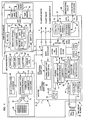
- a value metering system is an electronic postage meter system shown generally at 2, includes a removable printhead module 4 within a housing 5, a base module 6 and a secure internal accounting system module 8 and an external secure accounting system module 10 which will be hereafter explained in greater detail.
- the accounting systems include an internal accounting systems 8 and an external accounting system 10. These accounting systems account for the operation of the metering system and for the printing of postage value.
- Separate secure housings may be provided such as 7 or protecting the accounting system, and protecting the secure clock module 480 may be employed to protect the circuitry.
- a single secure housing or other housing arrangement may able be utilized to provide physical security and/or evident of tampering
- the print module 4 includes a printhead 12 which may be an ink jet printhead or other variable printing means.
- a printhead driver 14 provides the necessary signals and voltages to the printhead.
- a temperature sensor 16 is used to sense the ambient temperature. Since ambient temperature changes the viscosity of the printhead ink, this information enables change of the signals and voltages to the printhead to maintain a constant drop size.
- a smart card chip 18 which contains internal non-volatile storage receives encrypted command and control signals from the base unit and provides information to the ASIC 20 to operate the printhead driver 14.
- the ASIC may be of the type described in U.S. Patent No. 5,651,103 for a MAIL HANDLING APPARATUS AND PROCESS FOR PRINTING AN IMAGE COLUMN-BY-COLUMN IN REAL TIME, issued July 22, 1997, and assigned to Pitney Bowes, Inc.
- the ASIC is connected to a crystal clock 22, obtains the necessary operating program information from a ROM or flash memory 24 so as to appropriately control the sequence of the information to the ink printhead driver such that the printhead produces a valid and properly imprinted indicium (which herein is meant to include a digital token in whatever format it is to be imprinted).
- the base module includes a micro controller 26 which is connected to operate the electronic postage meter system motors and display and is coupled to the various accounting systems.
- the micro controller 26 is connected to a modem 28 which includes a modem chip 30 connected to a crystal clock 32 and a data access arrangement 34 for enabling modem communications between the metering system 2 and external systems.
- An RS 232 port 27 is provided.
- the RS 232 port 27 is connected to the micro controller 26 via a switch 29 which is operated under the control of the micro controller 26 such that either the RS 232 port 27 is enabled or the modem 28 is enabled. Should the RS 232 port 27 be enabled, the port may be used for communicating with the metering system by way of modem, direct connection or other serial communication technique suitable for RS 232 communications.
- the micro controller 26 additionally provides various control signals to operate the meter system including signals to the printhead carriage motor, the printhead shift motor and the printhead maintenance motor which are utilized to move position and maintain the printhead 12.
- the micro controller 26 is operated under control of two separate crystal clocks 36 and 38.
- the higher frequency 9.8 megahertz crystal clock is used when the electronic meter system is in active operation and the lower speed 32 kilohertz crystal clock 36 is used when the meter is in a "sleep mode" and the display is blanked and the system is in a quiescent state.
- Various power is provided to the micro computer and to the electronic postage meter system including a 5 volt regulated power supply 40, a 30 volt adjustable power supply 42, and a 24 volt regulated power supply 44.
- envelope sensor 52 which senses the presence of an envelope in the envelope slot of the metering system
- shift home sensor 54 which sense the home position of the shift motor (Y motor)
- cam home sensor 56 which senses the cam position which controls the envelope platen movement
- cover open sensor 57 Various electronic postage meter sensors are connected to the micro controller 26 including envelope sensor 52 which senses the presence of an envelope in the envelope slot of the metering system, shift home sensor 54, which sense the home position of the shift motor (Y motor), a cam home sensor 56 which senses the cam position which controls the envelope platen movement, and a cover open sensor 57.
- the micro controller 26 is additionally connected to a key pad 62 and an LCD Display Module 64. This enables a user to enter data into the metering system to view information show in the display 64.
- the metering system 2 employs two accounting systems.
- the first accounting system involves the internal smart card (or smart card chip) 8 and the second accounting system involves an external smart card 10.
- These smart cards are micro processor based devices which each provide for secure metering functionality.
- These smart card accounting systems or smart card vault systems securely maintain various registers associated with the metering system and provide the meter accounting functionality.
- the accounting systems provide for the capability of communicating register information and postage refilling and removal information to add or remove value from the various accounting registers.
- Each of the secure accounting systems generate the indicia and/or digital tokens needed to be imprinted on a mailpiece by the printhead 12.
- the modules provide for encrypted communications into and out of the accounting system such as may be associated with the funds refilling or funds debiting function.
- the accounting system provides for authentication of the printhead module smart card 18 and the accounting system. Whenever there is a request by a user through the keypad 62 or otherwise, to print postage, or whenever else it is desired, a mutual authentication occurs.
- the accounting system authenticates that it is in communication with a printhead module smart card chip 18, each authenticating the other as being authentic and valid metering systems. Thereafter encrypted communications are enabled between the active secure accounting system and the smart card chip 18 which is part of the printing system to provide security that the messages are authorized uncorrupted messages. This may be by way of a cryptographic certificate.
- the metering system 2 provides added functionality and capability to the system by the employment of the two separate accounting systems 8 and 10.
- the internal smart card accounting system 8 is connected to the micro controller 26 via a plug connector 66. This facilitates removal of the internal smart card 8 should external inspection be required where the device is inoperative.
- a 3.57 megahertz crystal clock 68 is connected to the smart card 8 and to the micro controller 26. Additionally, the clock 68 is connected to the external smart card 10 via the external smart card plug connector 70.
- the micro controller provides a smart card sensor switch 72 detects the presence or absence of the external smart card 10.
- the switch When the external smart card is detected as being present, the switch is connected to the micro controller 26 via the connector cable 74 causing the micro controller 26 to enable the external smart card power control circuitry 74 to apply power to the external smart card and gates the crystal clock 68 to provide clock signals to the external smart card 10, both via the smart card connector 70.
- the system is configured such that it may be a system operated with both the internal accounting system 8 and an external accounting 10, with only the internal accounting system 8 and only with the external accounting system 10. More over the external smart card 10 is arranged so that it can be connected to other electronic metering systems and provides a portable means for a user to have postal funds available for imprinting on a mail piece or tape on other than a specific postage metering system. However, even when connected to a different electronic postage metering system the same authentication between the external smart card 10 and the print head smart card chip 18 occurs.
- the system is designed with a priority arrangement. If no external secure accounting system, such as a smart card 10, is connected to the electronic postage meter system 2 the meter accounting functionality is provided by the internal secure accounting system smart card 8. This internal accounting system becomes the active accounting system for the metering system. However, if an external accounting system is connected into the system via the connector 70, the system will make the external accounting system, smart card 10, the active accounting system for the metering system 2.
- Connector 70 is a flexible multi purpose connector.
- the connector 70 enables connections of other types of smart cards such as card 76 which contains ad slogan information (alpha numerics and/or graphic information) card 78 which contains rate table information, and smart card 80 which contains authentication code information.
- card 76 which contains ad slogan information (alpha numerics and/or graphic information) card 78 which contains rate table information
- smart card 80 which contains authentication code information. It should be recognized that when each of these cards 76, 77 or 80 is connected into the system via the multi-function connector 70 a self authentication process is effectuated between the smart card and the print module smart card chip 18 to ensure that valid cards and data are being employed. It may use the same encryption and/or cryptographic certificate techniques to ensure valid authentic and uncorrupted message communication. This system may be used for moving information and data into and out of the meter system 2.
- the information of the type stored on cards 76, 77 and 80 are communicated from the card via the connector and the micro controller 26 to the smart card chip 18, the ASIC 20 and is stored in the flash memory 24 or the smart card chip 18 internal memory. For those embodiments which employ a ROM rather than a flash memory, the information is written into the print module smart card chip 18.
- a refilling operation for the metering system 2 may be remotely implemented via the modem 28 or RS232 connector 27.
- a remote connection is established via the modem 28 or RS 232 connector 27 to a remote data center. This enables bi-directional communication between the data center via the modem 28 or connector 27 via the micro controller 26 to either the internal accounting system 8 and/or the external accounting system 10 and to the print module smart card chip 18.
- the system is configured such that if an external smart card 10 is connected to the system via connector 70, the communications will be with the external smart card and not the internal smart card chip 8. It should be expressly recognized that other protocols can be implemented by use of the keyboard to designate which of the two accounting systems should be the active system for the purpose of recharging or other meter system operation.
- the communications involves the remote data center interrogating the internal or external accounting system to obtain necessary information such as the status of the funding registers (ascending register and descending register) other inspection information such as evidence of tampering, meter system serial number, internal resettable timer status and resets, and other information depending upon the nature of the particular system.
- the user may enter via the keyboard 62 a desired postage funding refill amount and upon suitable and successful interrogation of the active accounting system, the remote data center provides an encrypted recharging message which is communicated into the accounting system enabling refunding of the accounting system register with added additional postage value.
- communications in this matter enables remote inspection of the metering system integrity and to upload or download other information relating to the meter system operation such as monitoring the operability and maintenance from the print module 4. Additionally, if various meter usage information is maintained in the system, this information may be uploaded to the remote data center. Moreover, the remote data center provides a vehicle for downloading additional and new encryption key or keys into the system if so configured and provides the capability for other functionality and services such as meter usage profile. Moreover, at the time of remote meter resetting, a receipt may be caused to be imprinted by the print module as a receipt for the postage accounting system funds refilling. The receipt provides tangible evidence to the user of the date time amount and other pertinent data to the postage accounting system refilling transaction. The receipt may include transaction number and encrypted data such as a cryptographic certificate.
- the digital token is required to contain information concerning the physical location of the electronic postage of the metering system. This may be because of licensing requirements wherein a particularly meter is licensed to be operated in a particular location, as for example within a particular zip code area, the originating postal code of the mailer.
- the metering system 2 accommodates this requirement and enables the utilization of external smart card from originating zip locations other than that the of the license location for the metering system 2.
- the meter location information may also be important where it is required for use when metered mail must be deposited within the zip code or originating location of the mailer.
- the location of the metering system 2 is stored in the print module memory 4.
- This information may be the originating zip code for the mailer or other required location or other information.
- the information in the flash memory 24 or the smart card chip 18 is employed in imprinting a indicia or digital token on a mail piece by print head 12. It is necessary that the digital token generated either by the external smart card 10 or the internal smart card chip 18 be such that the digital token which contains originating postal code data be such that it is accurate and consistent with the data stored in the flash memory 24 or smart card chip 18 internal memory.
- the originating location data may be also stored in the internal accounting system 8.
- an external accounting system or smart card 10 is connected into the system, and a request for postage is initiated, as part of the authentication process, the communications is established between the external accounting system 10 and the print head smart card chip 18.
- a comparison is made between the originating location information stored in the flash memory 24 or smart card chip 18 internal memory and the originating location information stored in the external smart card 10. If there is a correspondence between these two location information storage, the printing of postage and generation of the digital token or indicia may proceed in the normal fashion with any other authentication and processing that may be employed.
- the location information stored in the flash memory 24 or smart card chip 18 internal memory is inconsistent with the location information stored in the external smart card 10, the system will not operate. At this time, the location information in the external smart card is over written or alternatively may be put in a separate memory location (a travel memory location). Correspondence now exist between the location information stored in the flash memory 24 or smart card chip 18 internal memory and the location information stored in the external smart card 10. Thus, when imprinting postage and generating digital tokens an agreement exists between the data generated on the mail piece from the location information in the flash memory 24 or smart card chip 18 internal memory and from the location information stored in the external smart card 10.
- the location information stored in the external smart card can be periodically checked against the location information stored in the flash memory 24 or smart card chip 18. Moreover, location information stored in both the flash memory 24 and the internal accounting system or external accounting system can be checked, if desired, whenever communications are established with the remote accounting center via the modem 28 or RS232 connector 27. Still further, should it be desired, a special purpose external smart card may be connected into the system to interrogate and verify various information stored both in the flash memory 24 and the internal smart card chip 18 or internal accounting system 8.
- a secure clock module 48 is connected to the micro controller 26.
- the secure clock module 48 includes a real time clock 49 which may be a continuous counter that continues operation whether or not the external power is applied to the metering system and an elapsed time counter 51.
- the elapsed time counter operates only when external system power is applied.
- Both the real time clock 49 and the elapsed time counter 51 are powered by a internal secure clock module battery/circuitry 53. When external power is removed from the meter system, the count of the elapsed time counter is maintained although it is no longer incremented. On the other hand, the real time clock continues to operate.
- the micro controller 26 includes an internal system time counter 33. This may be an internal module within the micro controller. Alternatively, it may be a separate external module connected to the micro controller in a way to operate as a systems time counter. It should be expressly noted the micro controller 26 system time counter 33 may be implemented in software as opposed to an external or internal micro controller module.
- the ROM 24 includes a country specific time zone offset 27 and a user settable offset 25.
- Time zone offset 27 provides an offset from Greenwich Mean Time. This time is set in the real time clock. This offset is specific to the particular location of the metering system in relation to Greenwich England.
- the user settable offset 29 is a user settable limited offset. This allows the meter user to offset the meter clock time to accommodate various issues. For example, the user may offset the clock for daylight savings time. Alternatively, the user may offset the meter system to accommodate different time zones within the particular specific country. The user offset 29 also allows the user to adjust when "midnight" occurs.
- This user offset may be limited to a specific number of hours, as for example, plus or minus 12 hours.
- the amount of the offset and whether it is a positive or negative offset may be determined by various criteria as, for example, the requirements of various postal services. Certain personal services may preclude the ability to move the clock backward.
- the ability to have a user settable offset 29, with a particular limitation on the number of hours of offset, provides flexibility in having a settable secure clock while providing the inherent clock security functionality (within the limits of the offset).
- a manufacturing facility 82 contains a clock setting application.
- the manufacturing facility connects to the metering system via a modem 84 or other form of connection such as RS232 port 85.
- Greenwich Mean Time is received from an external application at 202.
- the Greenwich Mean Time is loaded into the real time counter at 204 and into the elapsed time counter at 206. This provides an initial synchronization of the real time clock and the elapsed time clock at the time the value metering system is put into operation or the clocks activated.
- the elapsed time clock can have a different value loaded into it so long as it has a defined known relationship to the real time clock 204.
- the real time clock and elapsed time clock may be initialized to operate, if necessary.
- the GEM time is then calculated at 208. This GEM time is the form of the time used in the value metering system 2 for certain applications when a clock time is needed, as for example, those applications noted above.
- Real time clock 49 is loaded with the number of seconds elapsed since January 1, 1970, 00:00 Greenwich Mean Time.
- GEM time is the number of half days since January 1, 1992 and the number of seconds since the last 12:00 (midnight or noon).
- the country specific time zone offset 27 and user settable offset 29 is taken into account.
- the real time clock 49 is read at 302 and normalized to seconds since January 1, 1992 at 304.
- the time zone is adjusted at 306. This is an adjustment for the time zone offset.
- User offset is adjusted at 308.
- the number of half days since January 1, 1992 is calculated at 310 and stored and the number of seconds since noon or midnight remaining after the half day calculation is stored at 312.
- the data stored at steps 310 and 312 become the basis for the system time counter 33 (clock) in the micro controller 26 and the GEM time used in the system.
- the system time counter 33 continues during operation of the metering system to count seconds and when a noon or midnight is reached, increment the counting of half days. It should be recognized that the system time counter 33 associated with the micro controller has been converted by means of the secure clock module to have a real time related count or clock data usable by the system. This is because the system time counter is in synchronism with the secure clock module. Thus the micro controller 26 which normally does not have secure clock capability through the interaction of the micro controller clock and the secure clock module is made to have a secure real time data usable for various applications as noted above.
- the elapsed time counter 51 is read and saved as the last power down time at 402.
- the real time clock 49 time is read at 404.
- a determination is made at 406 if the real time clock 49 time is greater than the elapsed time counter 51 time, if it is not, an error code is displayed at 408 and value meter printing or any other selected function is disallowed or disabled at 410.
- the real time clock 49 time is great than the elapsed time counter 51 time
- the real time clock is stored in the elapsed time counter 51 at 412. This, again, synchronizes the elapsed time counter and the real time clock 49.
- the GEM time is calculated at 414. This is the call of the subroutine shown in FIGURE 3.
- FIGURE 5 After the value metering system 2 has been inactive for a predetermined period of time, as for example, ten minutes, the system may be put into an inactive or "sleep" state. At that time, the real time clock 49 is read at 502. The reading which is the sleep time is stored at 504 and the program branches back at 506 to continue the balance of any other sleep activity processing such as turning off displays, power supplies, sift crystal clocks, and the like, associated with shifting to a standby mode.
- any other sleep activity processing such as turning off displays, power supplies, sift crystal clocks, and the like, associated with shifting to a standby mode.
- the real time clock is read at 602.
- a determination is made at 604 if the real time clock 49 time is greater than the sleep time which has been stored at the time the meter became active. If the real time clock time is not greater than the sleep time, an error code is displayed at 606 and printing or other functions are disallowed or disabled at 608. If, on the other hand, the time clock 49 time is greater than the sleep time, the balance of the wake-up activity routine is invoked at 610.
- the meter is programmed to synchronize at midnight.
- the GEM time is calculated at 702 for midnight activity. This may be associated with conducting routine maintenance on the device such as purging the ink jet print head, resetting user settable features that may be set during the day such as advance date, advertising slogan, class of mail service, and the like, or other desired functionality. It should be recognized that midnight activity can be invoked at any desired time of the day or multiple times of the day as desired.
- This feature provides yet further security by re-synchronizing the meter system at predetermined times to ensure correct synchronization between the real time clock module 48 and the system time counter 33. Added security is also provided by checking the time relationship of the real time clock 49 and elapsed time counter 51 time in FIGURES 4 and 6 (or any other desired point in the process).
Abstract
Description
Claims (10)
- A system, comprising:a micro controller (26) having a system time counter (33);a secure clock module (48) connected to the micro controller (26); and,means interconnecting the secure clock module (48) and the system time counter (33) to provide a predetermined relationship between said system time counter and said secure clock module.
- A clock system (48) comprising:a real time clock (49) for maintaining a real clock time;an elapsed time clock (51) having storage for an elapse time therein; and,means for storing the real clock time into the elapsed time clock storage.
- A clock system as defined in Claim 2 wherein the means for storing real clock time into the elapsed time clock storage is implemented upon power up.
- A method of providing a system clock time, the method comprising: reading an elapsed time clock;reading a real time clock; and,storing the real time clock time in the elapsed time clock if the elapsed time clock has a predetermined relation to the real time clock.
- A method of providing a system clock time as defined in Claim 4 wherein the predetermined relationship is that the real time clock time is later in time than the elapsed time clock time.
- A method of providing a system clock time as defined in Claim 4 or 5 wherein the elapsed time clock time is a stored value of the elapsed time when a system employing clock time changed states.
- A method of providing a system clock time as defined in Claim 4, 5 or 6 further comprising:adjusting the elapsed time clock for time zone.
- A method of providing a system clock time as defined in any one of Claims 4 to 7 further comprising:adjusting the elapsed time clock for user offset.
- A method of providing a system clock time as defined in Claim 8 wherein the time adjusted for time zone and user offset is processed and is thereafter stored in a micro controller system time counter.
- A value metering system, comprising:a micro controller (26) having a system time counter (33);a secure clock module (48) connected to said micro controller (26), said secure clock having a real time clock (49) for maintaining real clock time and an elapsed time clock (51) having an elapse time storable therein with means for storing the real clock time into the elapsed time clock storage;means interconnecting the secure clock module (48) and the system time counter (33) to provide a predetermined relationship between said system time counter and said secure clock module; andprinting means (4) coupled to said micro controller (26) for printing an indicium whilst employing said system time counter time.
Priority Applications (1)
| Application Number | Priority Date | Filing Date | Title |
|---|---|---|---|
| DE69828331T DE69828331T3 (en) | 1997-04-30 | 1998-04-08 | Electronic postage meter with multiple clock systems for improved security |
Applications Claiming Priority (2)
| Application Number | Priority Date | Filing Date | Title |
|---|---|---|---|
| US846646 | 1997-04-30 | ||
| US08/846,646 US5999921A (en) | 1997-04-30 | 1997-04-30 | Electronic postage meter system having plural clock system providing enhanced security |
Publications (4)
| Publication Number | Publication Date |
|---|---|
| EP0875863A2 true EP0875863A2 (en) | 1998-11-04 |
| EP0875863A3 EP0875863A3 (en) | 2000-08-09 |
| EP0875863B1 EP0875863B1 (en) | 2004-12-29 |
| EP0875863B2 EP0875863B2 (en) | 2011-01-19 |
Family
ID=25298531
Family Applications (1)
| Application Number | Title | Priority Date | Filing Date |
|---|---|---|---|
| EP98106454A Expired - Lifetime EP0875863B2 (en) | 1997-04-30 | 1998-04-08 | Electronic postage meter system having plural clock systems providing enhanced security |
Country Status (4)
| Country | Link |
|---|---|
| US (1) | US5999921A (en) |
| EP (1) | EP0875863B2 (en) |
| CA (1) | CA2233759C (en) |
| DE (1) | DE69828331T3 (en) |
Cited By (1)
| Publication number | Priority date | Publication date | Assignee | Title |
|---|---|---|---|---|
| US8327448B2 (en) | 2005-06-22 | 2012-12-04 | Intel Corporation | Protected clock management based upon a non-trusted persistent time source |
Families Citing this family (23)
| Publication number | Priority date | Publication date | Assignee | Title |
|---|---|---|---|---|
| DE29806161U1 (en) * | 1998-04-06 | 1998-07-30 | Afg Elektronik Gmbh | Clock |
| US6757628B1 (en) * | 1998-07-14 | 2004-06-29 | Landis+Gyr Inc. | Multi-level transformer and line loss compensator and method |
| US20020111921A1 (en) * | 2001-02-09 | 2002-08-15 | Aupperle Bryan E. | Verification method for web-delivered materials |
| US20030145192A1 (en) * | 2001-10-30 | 2003-07-31 | Turner George Calvin | Measures to enhance the security and safety of mail within the postal system through the use of encrypted identity stamps, encrypted identity envelopes, encrypted indentity labels and seals |
| US7146504B2 (en) * | 2002-06-13 | 2006-12-05 | Microsoft Corporation | Secure clock on computing device such as may be required in connection with a trust-based system |
| US7234071B2 (en) * | 2002-11-29 | 2007-06-19 | Sigmatel, Inc. | On-chip realtime clock module has input buffer receiving operational and timing parameters and output buffer retrieving the parameters |
| US7370212B2 (en) | 2003-02-25 | 2008-05-06 | Microsoft Corporation | Issuing a publisher use license off-line in a digital rights management (DRM) system |
| US7116969B2 (en) * | 2004-02-12 | 2006-10-03 | Sharp Laboratories Of America, Inc. | Wireless device having a secure clock authentication method and apparatus |
| US7266714B2 (en) * | 2004-06-15 | 2007-09-04 | Dolby Laboratories Licensing Corporation | Method an apparatus for adjusting the time of a clock if it is determined that the degree of adjustment is within a limit based on the clocks initial time |
| US8438645B2 (en) | 2005-04-27 | 2013-05-07 | Microsoft Corporation | Secure clock with grace periods |
| US8725646B2 (en) | 2005-04-15 | 2014-05-13 | Microsoft Corporation | Output protection levels |
| US20060265758A1 (en) | 2005-05-20 | 2006-11-23 | Microsoft Corporation | Extensible media rights |
| US8682795B2 (en) * | 2005-09-16 | 2014-03-25 | Oracle International Corporation | Trusted information exchange based on trust agreements |
| US7613661B2 (en) * | 2006-08-02 | 2009-11-03 | Pitney Bowes Inc. | Method and system for detecting duplicate printing of indicia in a metering system |
| US20090222613A1 (en) * | 2008-02-29 | 2009-09-03 | Kabushiki Kaisha Toshiba | Information processing apparatus and nonvolatile semiconductor memory drive |
| US20090222614A1 (en) * | 2008-02-29 | 2009-09-03 | Kabushiki Kaisha Toshiba | Information processing apparatus and nonvolatile semiconductor memory drive |
| US20090228640A1 (en) * | 2008-03-07 | 2009-09-10 | Kabushiki Kaisha Toshiba | Information processing apparatus and non-volatile semiconductor memory drive |
| US8364930B2 (en) * | 2008-03-07 | 2013-01-29 | Kabushiki Kaisha Toshiba | Information processing apparatus and storage drive adapted to perform fault analysis by maintenance of tracing information |
| US8060453B2 (en) * | 2008-12-31 | 2011-11-15 | Pitney Bowes Inc. | System and method for funds recovery from an integrated postal security device |
| US8055936B2 (en) * | 2008-12-31 | 2011-11-08 | Pitney Bowes Inc. | System and method for data recovery in a disabled integrated circuit |
| US8344872B2 (en) * | 2009-12-10 | 2013-01-01 | Pitney Bowes Inc. | System and method for sensing presence of media in a mailing machine |
| US10404977B2 (en) * | 2014-12-03 | 2019-09-03 | Nec Display Solutions, Ltd. | Display device, usage management method and program of a display device |
| US11366934B2 (en) | 2018-11-13 | 2022-06-21 | Samsung Electronics Co., Ltd. | System and method for anti-rollback |
Citations (8)
| Publication number | Priority date | Publication date | Assignee | Title |
|---|---|---|---|---|
| US4725718A (en) | 1985-08-06 | 1988-02-16 | Pitney Bowes Inc. | Postage and mailing information applying system |
| US4757537A (en) | 1985-04-17 | 1988-07-12 | Pitney Bowes Inc. | System for detecting unaccounted for printing in a value printing system |
| US4775246A (en) | 1985-04-17 | 1988-10-04 | Pitney Bowes Inc. | System for detecting unaccounted for printing in a value printing system |
| US4796193A (en) | 1986-07-07 | 1989-01-03 | Pitney Bowes Inc. | Postage payment system where accounting for postage payment occurs at a time subsequent to the printing of the postage and employing a visual marking imprinted on the mailpiece to show that accounting has occurred |
| US4831555A (en) | 1985-08-06 | 1989-05-16 | Pitney Bowes Inc. | Unsecured postage applying system |
| US5293319A (en) | 1990-12-24 | 1994-03-08 | Pitney Bowes Inc. | Postage meter system |
| US5375172A (en) | 1986-07-07 | 1994-12-20 | Chrosny; Wojciech M. | Postage payment system employing encryption techniques and accounting for postage payment at a time subsequent to the printing of postage |
| EP0762692A2 (en) | 1995-08-21 | 1997-03-12 | Pitney Bowes Inc. | Secure user certification for electronic commerce employing value metering system |
Family Cites Families (43)
| Publication number | Priority date | Publication date | Assignee | Title |
|---|---|---|---|---|
| US3978457A (en) * | 1974-12-23 | 1976-08-31 | Pitney-Bowes, Inc. | Microcomputerized electronic postage meter system |
| US4168533A (en) * | 1976-01-14 | 1979-09-18 | Pitney-Bowes, Inc. | Microcomputerized miniature postage meter |
| US4122526A (en) * | 1976-12-20 | 1978-10-24 | Pitney-Bowes, Inc. | Calculating and postal zip code-to-postal zone converting apparatus |
| JPS53144377A (en) * | 1977-05-20 | 1978-12-15 | Sharp Corp | Repeating timer |
| US4301507A (en) * | 1979-10-30 | 1981-11-17 | Pitney Bowes Inc. | Electronic postage meter having plural computing systems |
| US4535419A (en) * | 1982-10-22 | 1985-08-13 | Pitney Bowes Inc. | System and method for computing fractional postage values |
| US4579054A (en) * | 1982-12-08 | 1986-04-01 | Pitney Bowes Inc. | Stand-alone electronic mailing machine |
| US4493252A (en) * | 1983-03-09 | 1985-01-15 | Pitney Bowes Inc. | Postage printing apparatus having a movable print head in a print drum |
| DE3501569C2 (en) * | 1984-01-20 | 1996-07-18 | Canon Kk | Data processing device |
| GB2173738B (en) * | 1985-04-19 | 1989-07-12 | Roneo Alcatel Ltd | Secure transport of information between electronic stations |
| US4812994A (en) * | 1985-08-06 | 1989-03-14 | Pitney Bowes Inc. | Postage meter locking system |
| US4802218A (en) * | 1986-11-26 | 1989-01-31 | Wright Technologies, L.P. | Automated transaction system |
| US4813912A (en) * | 1986-09-02 | 1989-03-21 | Pitney Bowes Inc. | Secured printer for a value printing system |
| US4858138A (en) * | 1986-09-02 | 1989-08-15 | Pitney Bowes, Inc. | Secure vault having electronic indicia for a value printing system |
| US4853523A (en) * | 1987-10-05 | 1989-08-01 | Pitney Bowes Inc. | Vault cartridge having capacitive coupling |
| US5111030A (en) * | 1988-02-08 | 1992-05-05 | Pitney Bowes Inc. | Postal charge accounting system |
| CA1301334C (en) * | 1988-02-08 | 1992-05-19 | Pitney Bowes Inc. | Postal charge accounting system |
| US5065000A (en) * | 1988-08-01 | 1991-11-12 | Pavo Pusic | Automated electronic postage meter having a direct acess bar code printer |
| US5051564A (en) * | 1989-01-03 | 1991-09-24 | Schmidt Alfred C | Method and apparatus for controlling a machine |
| US5237506A (en) * | 1990-02-16 | 1993-08-17 | Ascom Autelca Ag | Remote resetting postage meter |
| US5487096A (en) † | 1991-07-10 | 1996-01-23 | Dallas Semiconductor Corporation | Integrated circuit with real time, elapsed time, and cycle counter clocks |
| US5319562A (en) * | 1991-08-22 | 1994-06-07 | Whitehouse Harry T | System and method for purchase and application of postage using personal computer |
| JPH0553996A (en) * | 1991-08-29 | 1993-03-05 | Sharp Corp | Information processor with international timepiece function |
| US5440108A (en) * | 1991-10-11 | 1995-08-08 | Verifone, Inc. | System and method for dispensing and revalung cash cards |
| US5197042A (en) * | 1991-10-31 | 1993-03-23 | Pitney Bowes Inc. | Postage meter having auto dating device |
| GB9127477D0 (en) * | 1991-12-30 | 1992-02-19 | Alcatel Business Systems | Franking meter system |
| US5309363A (en) * | 1992-03-05 | 1994-05-03 | Frank M. Graves | Remotely rechargeable postage meter |
| GB9226813D0 (en) * | 1992-12-23 | 1993-02-17 | Neopost Ltd | Franking machine and method of franking |
| US5490077A (en) * | 1993-01-20 | 1996-02-06 | Francotyp-Postalia Gmbh | Method for data input into a postage meter machine, arrangement for franking postal matter and for producing an advert mark respectively allocated to a cost allocation account |
| FR2701781B1 (en) * | 1993-02-17 | 1995-03-31 | Neopost Ind | Franking machine allowing control of daily consumption. |
| FR2704343B1 (en) * | 1993-04-21 | 1995-07-13 | Secap | Two-part franking machine. |
| US5457642A (en) * | 1993-10-08 | 1995-10-10 | Pitney Bowes Inc. | Mail processing system including required data center verification |
| US5390251A (en) * | 1993-10-08 | 1995-02-14 | Pitney Bowes Inc. | Mail processing system including data center verification for mailpieces |
| US5483458A (en) * | 1993-12-09 | 1996-01-09 | Pitney Bowes Inc. | Programmable clock module for postage metering control system |
| GB9401757D0 (en) * | 1994-01-31 | 1994-03-23 | Neopost Ltd | Franking machine |
| GB9421489D0 (en) * | 1994-03-22 | 1994-12-07 | Optimum Solutions Limited | Electricity distribution & charging system |
| US5724425A (en) * | 1994-06-10 | 1998-03-03 | Sun Microsystems, Inc. | Method and apparatus for enhancing software security and distributing software |
| DE4422263A1 (en) * | 1994-06-24 | 1996-01-04 | Francotyp Postalia Gmbh | Method for coordinating the data stock between an electronic franking machine and a data center |
| US5613007A (en) * | 1994-11-30 | 1997-03-18 | Pitney Bowes Inc. | Portable thermal printing apparatus including a security device for detecting attempted unauthorized access |
| GB9500074D0 (en) * | 1995-01-04 | 1995-03-01 | Neopost Ltd | Franking machine system |
| US5625692A (en) * | 1995-01-23 | 1997-04-29 | International Business Machines Corporation | Method and system for a public key cryptosystem having proactive, robust, and recoverable distributed threshold secret sharing |
| FR2730082B1 (en) * | 1995-01-31 | 1997-04-18 | Neopost Ind | AUTOMATIC TIMING SYSTEM FOR POSTAGE MACHINE |
| US5933625A (en) * | 1995-12-11 | 1999-08-03 | Akira Sugiyama | Unique time generating device and authenticating device using the same |
-
1997
- 1997-04-30 US US08/846,646 patent/US5999921A/en not_active Expired - Lifetime
-
1998
- 1998-03-31 CA CA002233759A patent/CA2233759C/en not_active Expired - Fee Related
- 1998-04-08 DE DE69828331T patent/DE69828331T3/en not_active Expired - Lifetime
- 1998-04-08 EP EP98106454A patent/EP0875863B2/en not_active Expired - Lifetime
Patent Citations (8)
| Publication number | Priority date | Publication date | Assignee | Title |
|---|---|---|---|---|
| US4757537A (en) | 1985-04-17 | 1988-07-12 | Pitney Bowes Inc. | System for detecting unaccounted for printing in a value printing system |
| US4775246A (en) | 1985-04-17 | 1988-10-04 | Pitney Bowes Inc. | System for detecting unaccounted for printing in a value printing system |
| US4725718A (en) | 1985-08-06 | 1988-02-16 | Pitney Bowes Inc. | Postage and mailing information applying system |
| US4831555A (en) | 1985-08-06 | 1989-05-16 | Pitney Bowes Inc. | Unsecured postage applying system |
| US4796193A (en) | 1986-07-07 | 1989-01-03 | Pitney Bowes Inc. | Postage payment system where accounting for postage payment occurs at a time subsequent to the printing of the postage and employing a visual marking imprinted on the mailpiece to show that accounting has occurred |
| US5375172A (en) | 1986-07-07 | 1994-12-20 | Chrosny; Wojciech M. | Postage payment system employing encryption techniques and accounting for postage payment at a time subsequent to the printing of postage |
| US5293319A (en) | 1990-12-24 | 1994-03-08 | Pitney Bowes Inc. | Postage meter system |
| EP0762692A2 (en) | 1995-08-21 | 1997-03-12 | Pitney Bowes Inc. | Secure user certification for electronic commerce employing value metering system |
Cited By (1)
| Publication number | Priority date | Publication date | Assignee | Title |
|---|---|---|---|---|
| US8327448B2 (en) | 2005-06-22 | 2012-12-04 | Intel Corporation | Protected clock management based upon a non-trusted persistent time source |
Also Published As
| Publication number | Publication date |
|---|---|
| EP0875863A3 (en) | 2000-08-09 |
| EP0875863B1 (en) | 2004-12-29 |
| US5999921A (en) | 1999-12-07 |
| EP0875863B2 (en) | 2011-01-19 |
| CA2233759C (en) | 2000-11-28 |
| DE69828331D1 (en) | 2005-02-03 |
| DE69828331T3 (en) | 2011-08-18 |
| DE69828331T2 (en) | 2005-12-08 |
Similar Documents
| Publication | Publication Date | Title |
|---|---|---|
| EP0875863B1 (en) | Electronic postage meter system having plural clock systems providing enhanced security | |
| CA2212839C (en) | Electronic postage meter system having internal accounting system and removable external accounting system | |
| US6050486A (en) | Electronic postage meter system separable printer and accounting arrangement incorporating partition of indicia and accounting information | |
| US5655023A (en) | Advanced postage payment system employing pre-computed digital tokens and with enhanced security | |
| US5490077A (en) | Method for data input into a postage meter machine, arrangement for franking postal matter and for producing an advert mark respectively allocated to a cost allocation account | |
| CA1258916A (en) | System for detecting unaccounted for printing in a value printing system | |
| AU750777B2 (en) | Multiple registered postage meters | |
| US4760534A (en) | Mailing system with postage value transfer and accounting capability | |
| EP0782112B1 (en) | Transaction evidencing system and method including post printing and batch processing | |
| EP0825566B1 (en) | Electronic postage meter installation and location movement system | |
| US5812536A (en) | Secure accounting system employing RF communications for enhanced security and functionality | |
| AU765098B2 (en) | Postage metering system and method for a single vault dispensing postage to a plurality of printers | |
| US5946672A (en) | Electronic postage meter system having enhanced clock security | |
| US6023690A (en) | Method and apparatus for securely resetting a real time clock in a postage meter | |
| US20020002544A1 (en) | Method and apparatus for user-sealing of secured postage printing equipment | |
| CA2325609C (en) | Advance postage payment system employing pre-computed digital tokens and with enhanced security | |
| EP0939384A2 (en) | Postage printing system having secure reporting of printer errors | |
| MXPA97006446A (en) | Separable printer of the electronic release system and counting arrangement that incorporates individual division and information | |
| MXPA97006447A (en) | Electronic release system that has an internal counting system and a removable external counting system |
Legal Events
| Date | Code | Title | Description |
|---|---|---|---|
| PUAI | Public reference made under article 153(3) epc to a published international application that has entered the european phase |
Free format text: ORIGINAL CODE: 0009012 |
|
| AK | Designated contracting states |
Kind code of ref document: A2 Designated state(s): DE FR GB |
|
| AX | Request for extension of the european patent |
Free format text: AL;LT;LV;MK;RO;SI |
|
| PUAL | Search report despatched |
Free format text: ORIGINAL CODE: 0009013 |
|
| AK | Designated contracting states |
Kind code of ref document: A3 Designated state(s): AT BE CH CY DE DK ES FI FR GB GR IE IT LI LU MC NL PT SE |
|
| AX | Request for extension of the european patent |
Free format text: AL;LT;LV;MK;RO;SI |
|
| 17P | Request for examination filed |
Effective date: 20010208 |
|
| AKX | Designation fees paid |
Free format text: DE FR GB |
|
| 17Q | First examination report despatched |
Effective date: 20020418 |
|
| GRAP | Despatch of communication of intention to grant a patent |
Free format text: ORIGINAL CODE: EPIDOSNIGR1 |
|
| GRAS | Grant fee paid |
Free format text: ORIGINAL CODE: EPIDOSNIGR3 |
|
| GRAA | (expected) grant |
Free format text: ORIGINAL CODE: 0009210 |
|
| AK | Designated contracting states |
Kind code of ref document: B1 Designated state(s): DE FR GB |
|
| REG | Reference to a national code |
Ref country code: GB Ref legal event code: FG4D |
|
| REF | Corresponds to: |
Ref document number: 69828331 Country of ref document: DE Date of ref document: 20050203 Kind code of ref document: P |
|
| PLBI | Opposition filed |
Free format text: ORIGINAL CODE: 0009260 |
|
| PLAX | Notice of opposition and request to file observation + time limit sent |
Free format text: ORIGINAL CODE: EPIDOSNOBS2 |
|
| 26 | Opposition filed |
Opponent name: FRANCOTYP-POSTALIA GMBH Effective date: 20050929 |
|
| ET | Fr: translation filed | ||
| PLAF | Information modified related to communication of a notice of opposition and request to file observations + time limit |
Free format text: ORIGINAL CODE: EPIDOSCOBS2 |
|
| PLBB | Reply of patent proprietor to notice(s) of opposition received |
Free format text: ORIGINAL CODE: EPIDOSNOBS3 |
|
| RDAF | Communication despatched that patent is revoked |
Free format text: ORIGINAL CODE: EPIDOSNREV1 |
|
| APBP | Date of receipt of notice of appeal recorded |
Free format text: ORIGINAL CODE: EPIDOSNNOA2O |
|
| APAH | Appeal reference modified |
Free format text: ORIGINAL CODE: EPIDOSCREFNO |
|
| APBQ | Date of receipt of statement of grounds of appeal recorded |
Free format text: ORIGINAL CODE: EPIDOSNNOA3O |
|
| PLBP | Opposition withdrawn |
Free format text: ORIGINAL CODE: 0009264 |
|
| APBU | Appeal procedure closed |
Free format text: ORIGINAL CODE: EPIDOSNNOA9O |
|
| PUAH | Patent maintained in amended form |
Free format text: ORIGINAL CODE: 0009272 |
|
| STAA | Information on the status of an ep patent application or granted ep patent |
Free format text: STATUS: PATENT MAINTAINED AS AMENDED |
|
| 27A | Patent maintained in amended form |
Effective date: 20110119 |
|
| AK | Designated contracting states |
Kind code of ref document: B2 Designated state(s): DE FR GB |
|
| PGFP | Annual fee paid to national office [announced via postgrant information from national office to epo] |
Ref country code: DE Payment date: 20110427 Year of fee payment: 14 |
|
| REG | Reference to a national code |
Ref country code: DE Ref legal event code: R119 Ref document number: 69828331 Country of ref document: DE Effective date: 20121101 |
|
| PG25 | Lapsed in a contracting state [announced via postgrant information from national office to epo] |
Ref country code: DE Free format text: LAPSE BECAUSE OF NON-PAYMENT OF DUE FEES Effective date: 20121101 |
|
| REG | Reference to a national code |
Ref country code: FR Ref legal event code: PLFP Year of fee payment: 19 |
|
| PGFP | Annual fee paid to national office [announced via postgrant information from national office to epo] |
Ref country code: GB Payment date: 20160427 Year of fee payment: 19 |
|
| PGFP | Annual fee paid to national office [announced via postgrant information from national office to epo] |
Ref country code: FR Payment date: 20160425 Year of fee payment: 19 |
|
| GBPC | Gb: european patent ceased through non-payment of renewal fee |
Effective date: 20170408 |
|
| REG | Reference to a national code |
Ref country code: FR Ref legal event code: ST Effective date: 20171229 |
|
| PG25 | Lapsed in a contracting state [announced via postgrant information from national office to epo] |
Ref country code: FR Free format text: LAPSE BECAUSE OF NON-PAYMENT OF DUE FEES Effective date: 20170502 |
|
| PG25 | Lapsed in a contracting state [announced via postgrant information from national office to epo] |
Ref country code: GB Free format text: LAPSE BECAUSE OF NON-PAYMENT OF DUE FEES Effective date: 20170408 |