Field Of The Invention
This invention relates to Code Division Multiple Access (CDMA)
receivers and, more particularly, to a coherent MC-CDMA receiver using pilot
interference cancellation.
Background Of The Invention
Code-Division Multiple Access (CDMA) has become one of the most
prominent schemes for wireless communication systems. CDMA users are
distinguished from one another by different code sequences. Due to the wide
band nature of the CDMA signal, the receivers can be made robust against
fading by exploiting the built-in time diversity using a rake receiver. In a
coherent implementation of a rake receiver, a pilot signal is used to obtain the
amplitude and phase estimates of the channel needed for coherent detection.
As in the case of the S-95 CDMA system, the pilot signal is designed to be
orthogonal to the users' spreading codes so that in the rare case of no
multipath dispersion, the pilot signal will not cause interference at the matched
filter output for the desired user. However, if there is multipath dispersion, there
will be unwanted interference at the matched filter output due to a variety of
multipath components which are not orthogonal to the desired signal.
Specifically, for a given multipath component of a desired traffic channel, its
matched filter output will have unwanted contributions due to its other multipath
components and the other multipath components of the other channels and the
pilot signal. Since the pilot signal represents about 20 percent of the power of
the downlink signal, its multipath components can be especially damaging to a
desired user's bit decision via the near-far effect if the total number of active
traffic channels is high. Undesirably, conventional rake receivers do not
account for the interchannel multipath interference, and as a result, its
performance suffers.
Summary Of The Invention
In accordance with the present invention, a CDMA receiver is disclosed
which removes the pilot signal from the received signal. The pilot signal is
defined by its multipath parameters (amplitudes, phase shift and delays) and its
signature sequence. Since this information is known at the user's receiver
terminal (i.e., handset), the pilot signals of the interfering multipath components
of the baseband received signal are detected and removed prior to
demodulation of the desired multipath component.
More particularly, our CDMA receiver receives and demodulates a
coherent CDMA signal including at least one user data channel and a separate
pilot channel received over a plurality of L ( L > or = 2 ) paths, where the
desired data channel is orthogonal to the pilot channel for a given path. The
CDMA receiver comprises L path demodulators, each demodulator for
estimating a data channel and a pilot channel from a CDMA signal received
over one of the L paths and for generating L-1 cancellation signals each to be
used by a specific one of L subtractor means. Each of the L subtractor means
is used for subtracting the L-1 cancellation signals, produced by different ones
of the other L-1 path demodulators, from the CDMA signal associated with that
subtractor means.
In a pre-demodulation embodiment, the L-1 cancellation signals are
reconstructed pilot signals, and each of the subtractor means is located prior to
its associated demodulator to subtract the reconstructed pilot signals from the
signal inputted to its demodulator.
In a post-accumulation embodiment, each of the L-1 cancellation signals
is a pair of correlator-processed reconstructed pilot signals, and each of the
subtractor means is a pair of subtractors, located after a pilot and a data
accumulator of its demodulator, for subtracting the pair of correlator-processed
reconstructed pilot signals from the signal outputted from its data and pilot
accumulators.
According to another embodiment of the present invention, the pilot
signal cancellation can be switched on and off in response to a detected path
signal level which exceeds a predetermined level.
Brief Description Of The Drawings
Fig. 1 shows a typical transmitter of a CDMA communication link useful
in explaining the operations of the present invention, Fig. 2 shows a simplified block diagram of an illustrative CDMA receiver
that can be used at a mobile station , Fig. 3 shows a simplified block diagram of an illustrative CDMA receiver, Fig. 4 shows a prior art "RAKE" finger architecture for a coherent CDMA
receiver, Fig. 5 shows a basic demodulator structure of the Pilot-on-time and Data
1 on-time complex correlators, Fig. 6 shows an illustrative block diagram of our inventive pilot
cancellation scheme as applied to a two finger coherent CDMA receiver, Fig. 7 shows a first embodiment ( Detector A ) of a pre-demodulation
cancellation scheme in accordance with the present invention, Figs. 8 and 9 illustrate timing-charts for Detector A of Fig. 7 which show
how the channel estimates for pilot reconstruction are obtained with respect to
the symbol timing, Fig. 10 shows a Detector B which uses recursive pre-cancellation
without buffering, Fig. 11 shows the timing diagram for the Detector B of Fig. 10, Fig. 12 shows a Detector C which uses recursive pre-cancellation with
buffering, Fig. 13 shows a simplified illustration of the pre-cancellation scheme in
accordance with the present invention, Fig. 13A shows a simplified illustration of the post-cancellation scheme in
accordance with the present invention, Fig. 14 shows a diagram of a Detector D which uses post-cancellation, Fig. 15 shows the timing diagram for the Detector D of Fig. 14, Fig. 16 shows a diagram of a Detector E which uses multistage post-cancellation, Fig. 17 shows an illustrative block diagram of our inventive pilot
cancellation scheme (according to detector B) as applied to a three finger
coherent CDMA receiver, Figs. 18 -20 illustrate the need for pulse-shape Reconstruction Low Pass
Filter (RLP), Fig. 21 shows a FIR-implementation of a RLP, Fig. 22 shows an illustrative two finger coherent CDMA receiver
including switchable pilot interference cancellation, in accordance with the
present invention, and Fig. 23 shows an illustrative three finger coherent CDMA receiver
including switchable pilot interference cancellation.
Detailed Description
Shown in Fig. 1 is a transmitter for a synchronous pilot code aided
CDMA communication link, including the values given for IS-95. As shown in
an example, data signals from Users j and k at rate Rb (bit-rate, symbol-rate)
are coupled to code spreaders, e.g., 101j and 101k , where different orthogonal
Walsh codes of length g (g = 64) are used as user-individual spreading
sequences. The output of code spreaders 101j and 101k are combined
together with a pilot signal in adder 102 to form a Walsh-spread baseband
signal. There are at most g-1 data channels (including control channels) which
can be utilized at once (one channel is occupied by the pilot signal).
The Walsh-spread baseband signal, illustratively, at rate Rc is multiplied
in coders 104-105 by another PN-code spreading sequence, also called short
code or pilot code sequence.
This spreading (Walsh- and short-code spreading) widens the bandwidth
of the data signal over a broad frequency spectrum. The resulting chip-rate
signal occupies a g= R c / R b times larger bandwidth than the original symbol-rate
signal. The spreading sequence, illustratively, may be a periodic binary PN-sequence
(PN: Pseudo Noise), different for the I- and Q-channel (QPSK-spreading).
The spreading sequence is also called "chip-sequence" and thus
the processing rate after the spreading is called "chip-rate" Rc .
Note an unmodulated pilot code (Walsh-code 0, always +1, and its data
always +1) is embedded in the data signal as a phase reference for coherent
demodulation of the data channels at the receiver. One pilot channel for all
users is sufficient since it is a synchronous CDMA link.
The outputs from coders 104-105 are each filtered by FIR filters, 106
and 107, respectively. The outputs of the FIR filters 106 and 107 are then up-converted
by modulators 108 and 109 using radio carrier frequency signals
cos(ωct) and sin(ωct), respectively. The output of modulators 108 and 109 are
radio frequency signals which are combined in combiner 110 and transmitted
via antenna 111 over the air to the mobile user stations.
This radio frequency QPSK/CDMA signal includes all channels summed
together (data-channels, pilot channel). One bit in the baseband (also referred
to as symbol) at rate Rb consists of g 'chips' at rate Rc on the channel.
Illustratively, for an IS-95 type transmitter the parameters are:
Rb = 19.2kbps (kilobit per second), Rc = 1.2288Mcps (megachip per second), thus
g=64.
Fig. 2 shows a simplified block diagram of an illustrative CDMA receiver
that can be used at a mobile station. The radio frequency signals received via
antenna 201 are down-converted by modulators 202 and 203, using radio
frequency signals cos(ωct) and sin(ωct), respectively. The output of down
converters 202 and 203 are each filtered by an anti-aliasing LPF (Low Pass
Filter) 204 and 205, respectively to produce a resulting baseband I and Q
signals. The I and Q signals, are then further decoded and despreaded by a
CDMA RAKE receiver 208 operating under control of Digital Signal Processor
(DSP) 209 to produce the output data signal 210. The DSP forms a weighted
average of each of the data signals received by a different finger, where each
finger tracks a different multipath component.
Before we discuss the embodiment of our CDMA demodulator finger with
pilot interference cancellation, we first review the operations of a prior art
CDMA RAKE receiver. A RAKE receiver is an optimum mechanism for
receiving signals in a multipath environment when there is no interference due
to other users. In our CDMA system, there will be interference due to other
users; however, since the cross-correlations between the desired and
interfering signals are usually very low, the RAKE receiver provides very good
(but not optimum) performance.
An illustrative example of a RAKE receiver is described in the following
references
Fig. 3 shows an illustrative block diagram of a prior art RAKE receiver
typically used in a CDMA system. A RAKE receiver is used in both the forward
and reverse links of a CDMA system to take advantage of the inherent time
diversity in the received signals arriving via different paths of a multipath
environment.
Analog I signals (I) and Q signals (Q) are converted to digital signals by
the A/ D circuits 301 and 302, respectively. Control logic circuit 303, provides
Digital Signal Processor (DSP) interfacing and control, as well as common
timing and control functions for the CDMA receiver. Control logic circuit 303
operates under control of signals received over DSP bus from a DSP, not
shown. An RSSI (Received Signal Strength Indicator) block 304 calculates the
total received signal power of the I and Q signals received over the various
signal paths.
In a RAKE receiver, there are several (typically 4) mostly identical
"finger" units 305-308. Each of the finger units 305-308 is used to demodulate
a received signal arriving over a different air path of the multipath environment.
These finger units 305-308 are essentially the same except they have a
different time delay, attenuation and phase characteristics. The finger unit 308
additionally includes a small amount of additional logic to allow its use as a
high-speed pilot searcher (for use in coherent receivers to detect the Walsh
signal pilot shown in Fig. 1).
The pilot searcher finger 308 examines the incoming signal by
continuously correlating it with the pilot PN-sequence. It detects different base-stations
and multipath-components and delivers the respective PN-offsets to
the demodulator fingers 305-307.
Each demodulator finger performs a coherent demodulation of a certain
path of the incoming multipath-distorted signal.
Fig. 4 shows a typical embodiment of a RAKE finger for a coherent
CDMA receiver for use in a IS-95 forward link. A basic IS-95 RAKE finger in a
coherent CDMA receiver has three complex correlators, one for detecting pilot
on-time 402, one for detecting pilot early/late 403 and one for data-on-time 404(
which together recover the timing signals ). This arrangement allows the
decoding and despreading of data on a single Walsh channel by data complex
correlator 404. The data output of correlators 402-404 are then outputted over
DSP bus to a DSP unit, not shown.
The I/Q PN generator 405 provides input codes to the correlators 402-404.
The Walsh function generator 406 provides a Walsh code to the data
correlator 404. Control circuit 407 and slew control logic 408 provide control
signals for the operation of the RAKE finger and also interface to the DSP bus.
In the following description, conventional variable names are used and
are defined below:
- Tc
- Chip-Duration in seconds
- Rc = 1 / Tc
- Chip-rate, IS-95: 1.2288Mcps
- Rb = R c / N c
- Bit-rate ( = symbol-rate), IS-95: 19.2kbps
- Nc
- Number of chips per symbol (bit), IS-95: 64
- A
- Pilot gain (in comparison to single user amplitude)
- ρ
- Number of samples taken during one chip-interval (oversampling
factor) for each I- and Q-channel

- τ l = ρΔ l + δ l
- delay to path 0 in sub-chips; one chip consists of ρ sub-chips
(τ0 = 0 assumed)
- L
- Number of multipath components; indices are
l= 0...L-
- r (n) / (l)
- received signal vector of n-th symbol for multipath component I
(each vector element is a complex number), including noise from
other multipath components
- p (n) / (l)
- pseudo-random short code of n-th symbol for multipath
component l (also called short code, pilot code)
- s (n) / k(l)
- symbol signature code (Walsh-code) of n-th symbol for multipath
component l (user k), vector elements are real
- c and (n) / (l)
- complex channel estimate obtained from n-th symbol for multipath
component I (this is not a vector)
- c and (l)
- set of available channel estimates for multipath component l
- y (n) / (l)
- demodulator output of n-th symbol for multipath component l
-
- the received signal vector, ρRc
Conventional Receiver
With reference to Fig. 5, we describe the basic demodulator structure of
the Pilot-on-time and
Data 1 on time complex correlators ( 402 and 404 of Fig.
4, respectively) as a complex signal processing block diagram for a
multipath
component 0. The elements 501-504 provide the Pilot-on-
time correlator 402
function while 501-503, 507, 508 provide the
Data 1 on
time correlator 404
function. A complex graphical notation is used in Fig. 5 for simpler schematic
drawings and analysis. As shown, the input signal is
(i.e., the I
and Q inputs of Fig. 4).
The incoming signal r[i], illustratively, is an oversampled complex QPSK
DS/CDMA baseband signal ( after down conversion ) with ρ samples per chip-symbol.
The on-time selector 501 picks one out of ρ samples per chip for
further processing. By multiplying the signal r(0)[i] , in multiplier 503, with the
properly aligned short-code PN-sequence p (n) / (l) , received from complex
conjugate circuit 502, pilot despreading is performed. From the resulting signal
from multiplier 503, a channel estimate c and (n) / (l) is obtained from the upper
accumulator branch (accumulation over one symbol). The upper branch called
a 'channel estimation correlator' includes accumulator 504, optionally Channel
Estimation Algorithm Block (CAL) 505, and complex conjugate circuit 502.
Because the channel coefficients for a particular multipath may not vary much
from symbol to symbol, the channel coefficient estimate for the current symbol
may be enhanced by CAL 505 which produces a weighted average of all
available channel estimates and the current output from 504. Removing the
signature code s (n) / k(l) (Walsh-code for user k) the lower branch, or 'data
correlator' 507-508, recovers the binary information which gets aligned in the
signal space (phase/attenuation correction) by multiplying it, in multiplier 509,
with the complex conjugate channel estimate ( channel weighting ) from the
upper branch. The block 510 takes the real part of the complex signal from
multiplier 509 (the product of the channel estimate output and data correlator
output) and outputs it to the decoding part of the receiver (Viterbi decoder,
slicer, or multipath combiner), illustratively shown as a Digital Signal Processor
(DSP) 620 of Fig. 6.
Regarding CAL block 505, it should be noted that the channel estimates
c and (
n) / (
l) are taken at the symbol-rate. (It is important to mention that the channel
estimates
include the pilot channel amplitude since they are obtained by
correlating with the pilot channel.) It is common to take some sort of weighted
sum
e.g. a low-pass FIR-filtering - of the last
Nα channel estimates
(with
n as the index of the latest available channel estimate which can be
included in the channel estimate calculation algorithm) to get a more reliable
channel estimate. The gain of the CAL-algorithm is obviously limited by the
channel characteristics like fading and VCXO-offset since the channel
parameters should remain almost constant during the averaging (or: linear
interpolation also possible). If one considers the increasing complexity of CAL
it turns out that most of the time a channel estimate over one symbol is
sufficient. However, as will be discussed in a later paragraph, our pilot
cancellation schemes are not restricted to any channel estimation algorithm.
For the designs discussed in the following sections it is only important to
distinguish which channel estimates (the latest one?) can be included in the
CAL used for pilot reconstruction and which parts of the demodulation take
advantage of the cancellation. The demodulation always has knowledge of the
latest channel estimate, whereas the pilot reconstruction does not necessarily.
Regarding the accumulator block, it should be noted that it is assumed to
have a storage or hold element at its output. It holds the result of the latest
accumulation until updating it with a new result each symbol-clock cycle.
Based on the conventional receiver of Fig. 4, we present several
different implementation alternatives of our pilot cancellation scheme, both for
pre- and post-demodulation cancellation structures. Our structures utilize the
demodulation unit 520, which includes the elements or blocks 503-510.
To keep the drawings simple we, illustratively, focus on a 2-path signal
and thus 2 demodulator fingers, finger 0 and finger 1 are sufficient. The
extension to multiple paths/fingers is straightforward.
Pre-Demodulation Cancellation Schemes
In pre-demodulation cancellation schemes the pilot interference
cancellation (subtraction) is performed on the chip-samples.
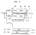
With reference to Fig. 6, we present an overview of our Pilot Interference
Cancellation (PIC) schemes. Illustratively, our receiver example of Fig. 6
receives signals over only two paths 611 and 612 and hence uses only two of
the typical three or more fingers of a receiver ( see Fig. 3 ). The fingers 603
and 604 operate to demodulate the different path signals 601 and
602,respectively, in the manner previously described. The receiver in our
example receives a composite signal r (n) and does not know that it includes
both the signals from path 0 and path 1. The signal of these paths 0 and 1
differ in attenuation α, phase and path delay τ. Since the pilot signals
represent about 20 percent of the power of the received path signal, we have
recognized that if the the pilot signal of path 1 can be eliminated from the
received signal of path 0, and vice-versa, the receiver can make a more
accurate demodulation.
With this in mind we have modified each finger 603 and 604, to
additionally include a pilot reconstruction circuit, shown as 606 and 607,
respectively, which recover the respective pilot signals from path 0, 611, and
path 1, 612. The received signal r (n) of path 0, r(0) is first processed by on-time
selector circuit (OTS) 601 and then by modified finger 603. The received signal
r (n) of path 1, r(1) is first processed by on-time selector circuit (OTS) 602 and
then by modified finger 604.
The pilot reconstruction circuits, 606 and 607, recover pilot signals with
estimated attenuation α, phase and path delay τ. As shown, the recovered
pilot signal from path 0 is subtracted (or cancelled ) in adder circuit 609 from
the path 1 signal. In our pre-cancellation schemes, the pilot interference
cancellation (subtraction) is performed on the chip-samples prior to
demodulation.
Similarly, the recovered pilot signal from path 1 is subtracted in adder
circuit 608 from the path 0 signal. The resulting path 0 and path 1 signals
minus the pilot signal of path 1 and path 0, respectively, are then more
accurately demodulated in finger 0 and finger 1, respectively. In the manner as
previously described, the output signals from fingers 0 and 1 are further
processed in a bit decision or a Viterbi decoder illustratively implemented in
DSP 605.
A. - Pilot Cancellation with Buffer (Detector A)
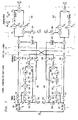
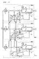
With reference to Fig. 7, there is shown a detailed implementation of a
two finger pre-cancellation arrangement using a symbol buffer for obtaining
latest channel estimates for pilot cancellation. In accordance with the present
invention, to use the channel estimate of the current symbol for reconstructing
the pilot and cancel it out prior to demodulation the data has to be buffered.
The processing is then done in 3 steps:
Fig. 7 shows a structure which works according this procedure. In the
following description, all of the "primed' numbered blocks operate in the same
manner as the non-primed numbered blocks. As shown, the blocks 501'-505',
509', and 520' operate the same as operate as blocks 501-505, 509, and 520
previously described in Fig. 5. The blocks 700 and 700' are separate pilot
detectors which use channel estimates (obtained using 504-505 and 504'-505')
that have been normalized (by 705 and 705'). The pulse-shaping for the pilot
detectors 700 and 700' is taken into account using RLP blocks 701 and 701'
(Reconstruction Low-Pass Filter), respectively. The RLPs 701 and 701' are
necessary if the delays are not in multiples of the chip-duration. Note, if we did
not consider the pulse-shaping the Bit Error Rate (BER) would increase. The
implementation of an RLP is described in a later section.
The symbol buffers 703-704 and 703'-704' enable the symbol data to be
buffered while the pilot detectors 701 and 701' are reconstructing the pilot
signal.
To compensate for the delay introduced by an RLP in one branch, a
small RLP-delay buffer z-D is needed (with D as the RLP-delay in chip-samples,
D = N / 2, N number of taps of RLP-filter) to be added to the other branch. Thus,
delays z -D 702 and 702' compensate for RLP 701 and 701', respectively.
Optionally, for delay offsets in the range of some chips (small in
comparison to the total number of chips per symbol), the influence of an
alignment-buffer
shown as delays 706-708 and 706'-708',
may be considered. We have determined that such effects are negligible,
since in a practical implementation the combination of all finger outputs is
performed on the symbol-rate. Therefore, no alignment-buffers 706-708 and
706'-708' are needed anyway. Keeping this in mind the hardware required for
an alignment-buffer at the chip-sample level is not justified. Therefore we leave
it out in our later disclosed embodiments.
After the pilot signal, of path 0, has been recovered in pilot detector 700,
it is applied to the adder 711" to be subtracted from the path 1 signal prior to
the demodulation of that signal, by demodulator 520'. The non-pulse-shaped
(just delayed, see paragraph on RLP) output from RLP block 701 of pilot
detector 700 is delayed and conjugated and used as an input to multiplier 503.
Similarly, the pilot signal, of path 1, recovered in pilot detector 701', is applied
to the adder 711 to be subtracted from the path 0 signal prior to the
demodulation of that signal, by demodulator 520. And, the non-pulse-shaped
output from RLP block 701' of pilot detector 700' is delayed and conjugated and
used as an input to multiplier 503.
In accordance with another embodiment, the detector A is modified so
that the channel estimate ( obtained in 700 and 700' ), which is used for the
pilot reconstruction, is also used for the demodulation process ( by
demodulators 520 and 520' ). In such an arrangement, we do not need two
phase estimation accumulations and CAL-blocks per finger. However by doing
this, only the data correlator benefits from the pilot cancellation and thus this
arrangement will have a weaker BER-performance. The same slight variation is
also possible for our later described detector C.
With reference to Figs. 8 and 9, we describe the timing aspects of the
detector A of Fig. 7. The timing-chart of Fig. 8 shows how the channel
estimates for pilot reconstruction are obtained with respect to the symbol
timing. The symbol-buffers (e.g., 703) guarantees that the pilot cancellation for
symbol n can be performed with a channel estimate obtained from data of
symbol n (latest channel estimate available). The alignment-buffers (e.g., 706)
guarantees that the new channel estimates for pilot cancellation are available at
the beginning of the demodulation process.
Shown in Fig. 9 is a timing-chart where the channel estimates for pilot
reconstruction do not use alignment-buffers. The performance degradation
without alignment-buffer will be negligible if the delay offset τ1 is in the
dimension of some chips (τ0 = 0 assumed).
Performance - Detector A
In a Rayleigh-fading environment, the advantage of detector A is that it
has the latest channel estimate available for pilot reconstruction which has a
positive effect on the BER if the channel characteristics are likely to vary
significantly from symbol to symbol.
However, in an AWGN-channel there will be no improvement (to detector
B) since the channel characteristics do not change from symbol to symbol.
The channel estimates for reconstructing the pilot signals are obtained
from a signal which did not go through a cancellation stage - to this respect a
recursive structure like discussed in the next section will have some
advantages since there the channel estimates are taken from data which has
already gone through a cancellation stage and therefore is affected by less
noise.
In practice the chip-samples have a 4 bit resolution (I- and Q-samples).
Thus the whole pilot reconstruction processing can work with a low bit
resolution (RLP: 4 bit, multiplications at chip-rate: 4 bit). If we did not consider
the pulse-shaping we even would not need multiplications at the chip-rate.
Another way to get rid of the chip-rate multiplications is explained in the later-described
post-demodulation schemes.
B - Recursive Structure without Buffer (Detector B)
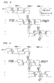
Shown in Fig. 10 is a receiver that uses recursive pre-cancellation
without working with previous channel estimates. This structure is the most
attractive one for implementation, since there is no buffering required. The
additional hardware efforts are minimal. The channel estimates 1001 and
1001' used for demodulation of the previous symbol n-1, from demodulators
520 ( finger 0) and 520' ( finger 1) , are reused, respectively, for
reconstructing the pilot signal and cancellation of the next symbol n of fingers 0
and 1, respectively. The pilot reconstruction is done in circuits 1010 and 1010'.
The cancellation is performed in the subtractors 711, 711'. The remaining
blocks of Detector B operate in the same manner as the identically numbered
blocks of previous Figures.
Shown in Fig. 11 is a timing-chart for Detector B showing the channel
estimates timing for pilot reconstruction. It can be seen that the pilot
cancellation for symbol n operates with a channel estimate obtained from data
of symbol n-1 (small parts work with estimates of symbol n, n-2).
Performance - Detector B
The disadvantage of this structure is that the latest channel estimate is
not available for cancellation; this can result in performance degradation in a
fast fading environment.
However, the recursive loop - here a must - provides a nice side-effect:
Now even the channel estimates used for reconstructing the pilot signals are
obtained from data which went through a pilot cancellation stage previously.
C-- Recursive Structure with Buffer (Detector C)
The Fig. 12 shows a combination of the two ideas introduced above:
First, using a buffer (i.e., 703 and 703') for having the latest channel estimate
available in the CAL for pilot reconstruction ( by 700 and 700' ); and second, a
recursive loop (i.e., 1010 and 1010' ) so that even the channel estimation of
the pilot reconstruction benefits from a previous pilot cancellation. As shown
the recursive loop block 1010' enables ( using adder 1210) a detected pilot
signal from path 1 to be subtracted from the signal inputted to the pilot detector
700 of the path 0. Similarly, the recursive loop block 1010 enables ( using
adder 1210' ) a detected pilot signal from path 0 to be subtracted from the
signal inputted to the pilot detector 700' of the path 1. Again, the remaining
blocks of Detector C operate in the same manner as the identically numbered
blocks of previous Figures.
The timing-chart ,not shown, for Detector C which uses the channel
estimates for the pilot reconstruction, is similar to that of Detector A except that
now there is an additional cancellation that potentially offers better channel
estimates for the pilot reconstruction.
Performance - Detector C
Detector C combines both the latest channel estimate available for pilot
reconstruction, and a channel estimate for pilot reconstruction which is obtained
from data which benefits from a previous cancellation. However, the
performance gain over detector B may not be striking enough to justify the
additional hardware complexity (symbol-buffer, a second pilot reconstruction
processing with RLP and multiplications at the chip-rate are needed).
Post-Accumulation Cancellation Schemes
In these post-cancellation schemes the pilot cancellation (subtraction) is
performed at the symbol rate Rb. The motivation to do post-cancellation is to
get rid of multiplications at the chip-rate Rc.
A - Post-Demodulation Cancellation (Detector D)
In the pre-cancellation schemes, e.g., Fig. 13, the reconstructed pilot
signal
gets cancelled out from the received signal
r[
i] ( in adder 1300 )
at the chip-rate prior to demodulation. In Fig. 13A the cancellation stage
(
adders 1301 and 1302 ) is placed after the accumulators ( 1303 and 1304 ), to
perform the cancellation on the symbol-rate samples.
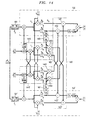
With reference to Fig. 14, the Detector D is shown including on-time
selectors 501 and 501'; CAL circuits 1401 and 1401'; demodulators 520 and
520'; pilot detectors 1410 and 1410'; and adder circuit 1420. The operations of
on-time selectors 501 and 501' and demodulators 520 and 520' have previously
been described.
The Detector D uses a reconstructed pilot signal which is accumulated
separately ( in pilot detectors 1410 and 1410' ) and multiplied ( in multipliers
1402 , 1403 and 1402', 1403' ) by the channel estimate ( from demodulators
520 and 520' and CAL circuits 1401 and 1401' ) at the symbol-rate Rb. The
resulting pilot signals from 1402 and 1402' are then summed in adders 1421
and 1421' to the traffic ( data ) signal of demodulators 520 and 520',
respectively. The resulting pilot signals from 1403 and 1403' are then summed
in adders 1422 and 1422 to the channel estimates of demodulators 520 and
520', respectively.
A nice side-effect of post-cancellation is that there is no symbol-buffer
(e.g., 703 of Fig. 7) necessary anymore (and even no alignment-buffer, e.g.,
706) to include the latest channel estimate in the CAL for pilot reconstruction,
since the channel estimate multiplication is delayed up to the end of the current
symbol.
The structure of Detector D is equivalent to detector A, shown in Fig. 7,
with alignment-buffer but needs neither a symbol-buffer nor an alignment-buffer.
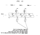
Shown in Fig. 15 is a timing diagram for Detector D. As shown, the
results of accumulators ,at symbol rate Rb, are held until all paths are time-aligned
( delay offsets are usually smaller than symbol durations) and then the
cancellation is performed with the latest channel estimates. It should be
mentioned that the delay-alignment control (accumulator outputs are held) at
the symbol-rate is not explicitly shown in the drawings.
The performance of Detector D is similar to that of Detector A.
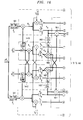
B - Multistage Post-Cancellation (Detector E)
The Detector D post-cancellation scheme did not cancel the pilot signal
using a channel estimate which itself took advantage of a previous pilot
cancellation. The structure of Detector E does as is shown in Fig. 16.
Detector E is shown including on-time selectors 501 and 501'; CAL
circuits 1401 and 1401'; demodulators 520 and 520'; pilot detectors 1410 and
1410'; adder circuit 1420; and multipliers 1402,1403 and 1402',1403', the
operations of which have previously been described. Additionally, Detector E
includes CAL circuits 1601 and 1601' and multipliers 1602 and 1602' which
provide a first cancellation stage where only the channel estimate of 1410 and
1410' gets refined. Thereafter, using the better channel estimate the the actual
cancellation is performed in adder circuit 1420.
The timing diagram of Detector E is the same as that for Detector
D,shown in Fig. 15.
Performance Detector E
The performance of Detector E will be close (slightly better) to Detector
C, since all channel estimates used for pilot reconstruction or prior to
cancellation are the latest ones.
It is clear that we could have any number of cancellation stages for
obtaining a better channel estimate. But most probably even a single one is
not worth implementing in a handset receiver ( Fig. 2 ) since the benefit of
having a slightly better channel estimate is not significant.
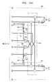
E - Example of a 3 finger structure
Shown in Fig. 17 is an illustrative arrangement of a three finger (3 path )
receiver that uses recursive pre-cancellation without buffer working with
previous channel estimates ( i.e., Detector B of Fig. 10 ). For the IS-95 handset
receiver a 3 finger design is proposed.
The RLP , e.g., 601, now has 2 outputs since the two other fingers, 1
and 2, can have different timing for their on-time samples. Thus the
reconstruction of pulse-shape of e.g., pilot 0, needs two different fractional
delay offsets δ1, δ2 for finger 1, and 2. Note, that in finger 0 ( path 0 ) the pilot
from both fingers 1 and 2 ( paths 1 and 2 ) are cancelled from the signal
inputted to finger 0. Similarly, fingers 1 and 2 also have the respective pilot
signal signals of the other channels cancelled from their input signals. The
remaining parts of this receiver operates the same as Detector previously
described for Detector B of Fig. 10.
Reconstruction Low-Pass Filter (RLP)
Most of the time there will be multipath components which are delayed in
fractions of Tc (δ l ≠ 0). Then the pulse-shaping has to be taken into account.
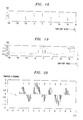
A - Need for Reconstructing the Pulse-Shape
The Figs. 18-20 illustrate the need of a pulse-shape Reconstruction Low-Pass
filter (RLP) when the timing offsets of the multipath components are not in
multiples of
Tc . A part of the sampled pilot signal (e.g. the l-channel) of
multipath component 0 is shown. For this example, it is further assumed that
the sampling times are
Ts =
i·
Tc / ρ
, i integer, no I/Q-phase shift, and that the
signal is normalized to 1 at the on-time samples.
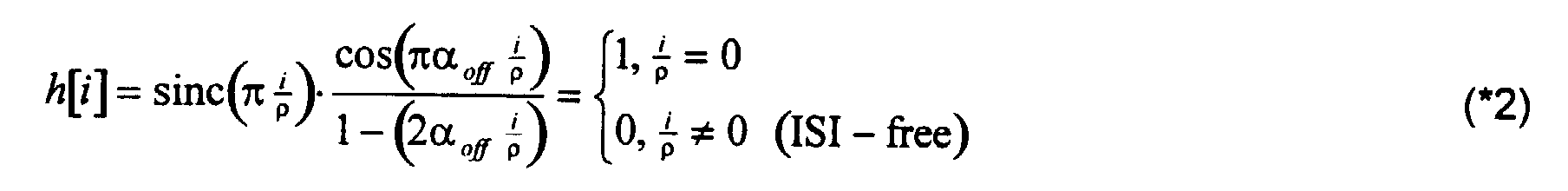
with normalized Nyquist pulse shape
and roll-off factor α
off (IS-95: α
off ≈ 0. );
i is a sub-chip sample index.
Shown in Fig. 18 is a short-code sequence, with signal P[i] with sub-chip
index.
Shown in Fig. 19 is a normalized time domain impulse response of a
Nyquist-raised cosine filter, up to 4 sidelobes.
Shown in Fig. 20 is an example of the pulse-shaped pilot for multipath
component 0. The above pilot signal may belong to multipath component 0.
Then the on-time samples at the chip-rate are (ideally) either +1 or -1
(normalized) since a Nyquist-pulse shaping filter was used in the transmitter (no
ISI of neighbor-impulses at the on-time samples). (Actually, there is a square-root
Nyquist raised filter in the transmitter. Together with the pulse shape
matched filter in the receiver [also a square-root Nyquist raised filter ] one
obtains a Nyquist raised cosine pulse shaping in the baseband of the receiver.).
To cancel out this pilot signal from other multipath components ( fingers )
- e.g. component 1 - we have to consider the pulse-shape of the pilot signal 0
at the on-time samples of the respective multipath component 1. In other
words, to cancel out the pilot signal of multipath component 0 from component
1, we have to reconstruct the pulse-shape of pilot 0 at the on-time samples of
signal 1 (RLP-coefficients a j,δ1 ). Since we no longer assume delays in multiples
of Tc , the on-time samples of component 1 could be somewhere 'in between'
(that means: δ1 ≠ 0) and therefore according to (*1) the pulse-shape of pilot
signal 0 is of importance.
The FIR-implementation of the reconstruction low-pass filter is fairly
simple. We approximate the discrete convolution summation in (*1) by a finite
number of N taps (N is an even number).
Shown in Fig 21 is a FIR-implementation of a Reconstruction Low-Pass
filter (RLP). The FIR-coefficients are
a j,δ =
h[(
j-
N / 2)·ρ+δ] and therefore
dependent on the
fractional part 6 of the delay τ=ρΔ+δ. For δ=0 only
a N 2 ,0 = ;
the other coefficients become zero. This is true for delays that are
integer multiples of
Tc . The pulse-shaped output at the chip-rate is
now with
i as a chip-sample index, and
pI,Q [
i] as the short-code sequence.
Additional Implementations
In simulations of fast fading environments it turns out that pilot
interference cancellation should only be performed if the channel estimate used
for pilot signal reconstruction is obtained from a multipath component which
exceeds a certain power threshold. Otherwise, we may unnecessarily reduce
the BER-advantage of pilot cancellation by using bad channel estimates.
For this purpose a simple switch is added to each finger of the presented
designs which switches off the pilot cancellation for the respective multipath
component if the received signal-power of that component is too small (due to a
short deep fade). The signal power of each multipath component is calculated
anyway in a practical implementation. Thus, there is no additional hardware
required - except for the switch and a threshold detector.
According to another feature of the present invention, a switch controls
whether pilot interference cancellation for a particular pilot signal should or
should not occur. The decision for this switch is optimum according to a
minimum mean-squared error criterion (MMSE), and can be implemented using
linear combiners and a threshold device. Hence with a simple decision device,
we can determine the optimum set of pilots to cancel and theoretically improve
the performance of our pilot interference cancellation system.
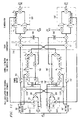
Figure 22 shows an enhanced PIC detector or receiver of Fig. 6.with the
added switch capability(2201, 2202) controlled by Decision unit 2203. Let
G and (n) / l be the set of pilots which are canceled for the l th finger during symbol
interval n. Since pilot I is required to estimate the channel for path l, it cannot be
canceled from finger l. Hence G and (n) / l is a subset of the set
{0,1,···,j,···,L -1; j ≠ l . (For example, if L = 3 then an allowable group of
cancellation sets is G and (n) / 0 = {1,2}, G and (n) / 1 = {0,2}, and G and (n) / 2 = {0}.) Using the criteria
derived in the following section and the channel estimates c and (n) / 0 and c and (n) / 1, the
Decision unit 2203 determines the cancellation sets G and (n+1) / 0 and G and (n+1) / 1 for pilot
cancellation on the next symbol interval. If G and (n+1) / 1 = {0}, the top switch is on, and
pilot 0 is reconstructed using c and (n) / 0 and canceled from the input to finger 1 on the
next symbol interval. Otherwise, if G and (n+1) / 1 = Ø, then switch 2201 is off and no pilot
0 signal cancellation occurs for finger 1. Likewise, if G and (n+1) / 0 = {1}, the bottom switch
is on, and pilot 1 is reconstructed using c and (n) / 1 and canceled from the input to
finger 1 on the next symbol interval. Otherwise, G and (n+1) / 0 = Ø then switch 2203 is off
and no pilot 1 signal cancellation occurs for finger 0.
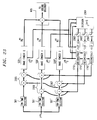
Figure 23 shows the implementation for an L = 3 finger RAKE receiver.
Fig. 23 is essentially Fig. 17 with the addition of Decision unit 2301 and
switches 2202 and 2204. Note that we must reconstruct L - 1 versions of pilot l,
each using a separate Reconstruction Low-Pass Filter (RLPF), to match the
multipath delay of the finger from which we are canceling the pilot. For
example, for path 0 we construct the pilot signal for paths 1 and 2(in 1710' and
1710", respectively) which must then be subtracted from the path 0 signal
(using adders 2305). Similarly, pilots 0 and 1 are subtracted from the path 2
signals (using 2307) and pilots 0 and 2 are subtracted from path 1 signals
(using 2306).
Derivation of the Switch Mechanism
We now derive the MMSE switch set for pilot interference cancellation.
Our goal is to determine the switch sets
G and (
n) / 0,···,
G and (
n) /
L-1 which minimize the mean-squared
error of the sum of RAKE finger outputs. The output of finger
l is a
function of the switch set
Hence our objective is to evaluate the
following:
where
and the expectation is taken with respect to the random
spreading codes, the interferers' data bits, and the background thermal noise.
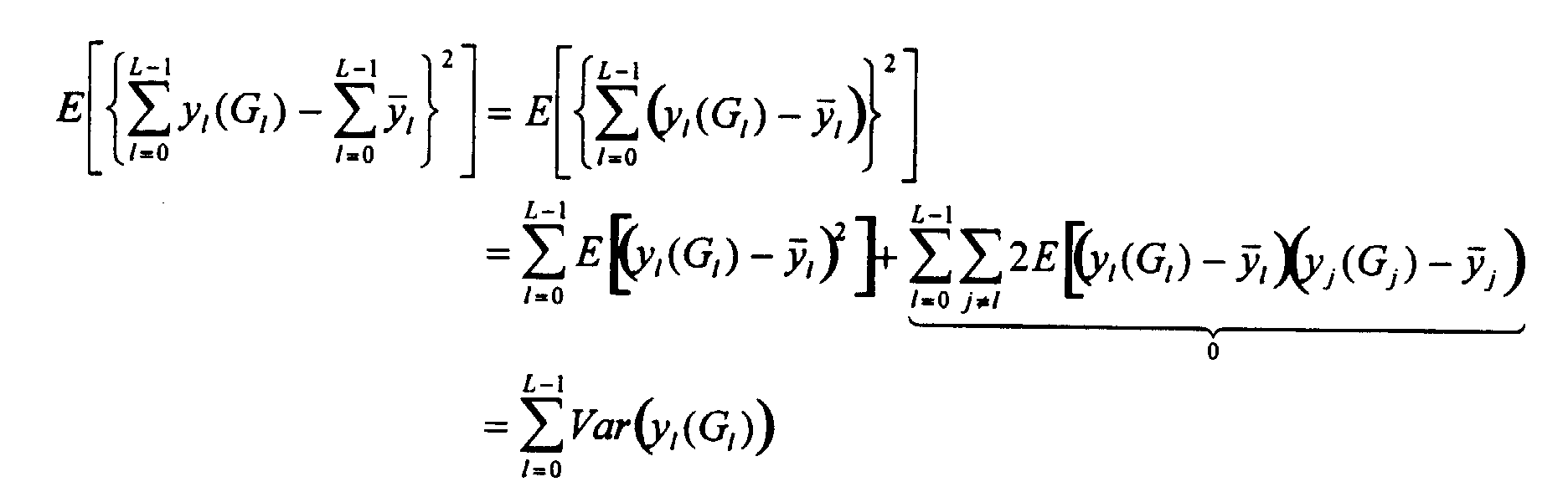
Evaluating the right hand side of (3), we have
Hence the variance of the sum is the sum of the variances, and it follows
that our original decision rule in (3) becomes
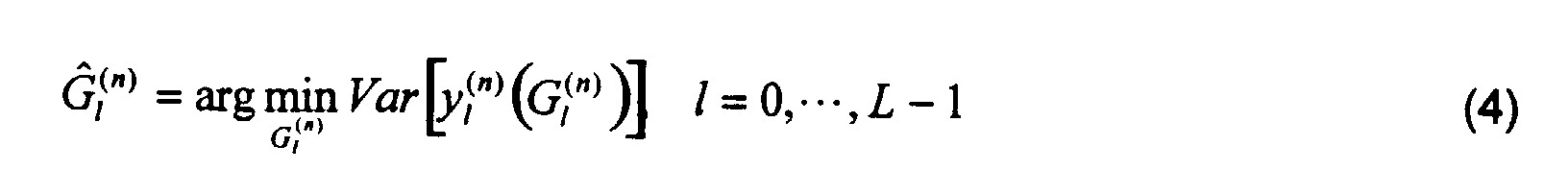
It can be shown that the MMSE set
G and (
n) /
l is:
Of course since the actual channel parameter
c (
n) /
j is not known, we should use
its estimate
c and (
n) /
j(
G and (
n) /
j in the decision. However, this substitution would lead to a
dependence of
G and (
n) /
l on itself. To remedy this situation, we make the
assumption that the channel variations between symbols is relatively small, and
consequently, we can use
c and (
n-1) /
j(
G and (
n-1) /
j) in place of
c and (
n) /
j(
G and (
n) /
j) to give us the
cancellation set:
The decision to cancel pilot
j depends only on the corresponding estimated
channel power
and the variance of the channel estimate. The
intuition behind this decision is clear: if the power of a pilot signal
j is stronger
than the variance of its estimate, then the reconstructed pilot interference
based on
c (
n) /
j is reliable enough so that removing it from the finger input will
lower its output MSE. Otherwise, if the power is too weak, removing the
reconstructed pilot interference will actually increase the output MSE. Except
for the condition that
j ≠
l, this decision does not depend on the finger
l, the
target finger for pilot interference cancellation. Consequently, the set
G and (
n) /
l is not
a function of
l, except of course that
I is never a member of
G and (
n) /
l since we are not
allowed to cancel pilot
I from finger
l. With this exception in mind, we can
represent
G and (
n) / 0···
G and (
n) /
L-1 with
G and (n). Note that the cancellation sets given in our earlier
example,
G and (
n) / 0 = {1,2},
G and (
n) / 1 = {0,2}, and
G and (
n) / 2 = {0}, are not allowable according to (5)
or (6) since
pilot 1 is canceled from
finger 0 but not from
finger 2. A valid group
of cancellation sets would be
G and (
n) / 0 = {2},
G and (
n) / 1 = {0,2}, and
G and (
n) / 2 = {0}; these sets are
represented using
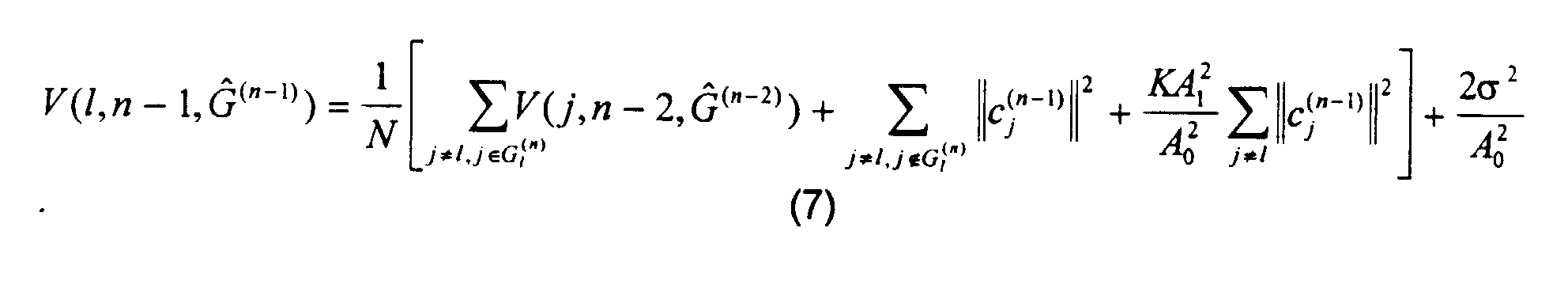
G and (n) = {0,2} Defining
it can be
shown that:
where
N is the spreading factor (
N = 64 for IS-95),
K is the number of active
data/sync channels, 2σ
2 is the thermal noise power per chip,
A 0 is the pilot
amplitude and
A 1 is the amplitude of each of the
K data/sync channels. Using
the channel estimate from symbol interval
n - 2 in place of the actual channel
parameter from symbol interval
n - 1, (7) becomes
Hence on each symbol interval, the cancellation set
G and (
n) /
l (
l = 0···
L-1) is
determined using the following steps:
- Calculate the channel estimate variances V(l,n-1,G and (n-1)) for l = 0···L-1 using
(8).
- Deterrnine G and (n) / l (l = 0···L-1) using (6).
In summary, the above derived switch mechanism for a pilot interference
cancellation detector provides minimum mean-squared error rake detector
outputs. The resulting decision rule for the switch is: if the power of the channel
estimate for path l (l = 0··· L-1) is high (i.e., greater than the variance of this
estimate), then the associated pilot signal reconstructed using this channel
estimate is reliable and should be canceled from the other L - 1 rake finger
inputs; otherwise, if the power of the channel estimate is low, then the
reconstructed pilot signal is unreliable and cancellation using this pilot should
not occur.
While our inventive CDMA receiver has been described for use in a
forward link utilizing a Walsh code pilot frequency and Walsh encoding to
provide coherent operation, it should be noted that many other well known
codes which maintain coherent operations may also be utilized in both the
CDMA transmitter and CDMA receiver (typically in the forward link). Moreover,
our coherent receivers while described for use in a coherent forward link they
may also be used in a coherent reverse link.