EP0876805A2 - Intravascular stent and stent delivery system for ostial vessel obstructions - Google Patents
Intravascular stent and stent delivery system for ostial vessel obstructions Download PDFInfo
- Publication number
- EP0876805A2 EP0876805A2 EP98303535A EP98303535A EP0876805A2 EP 0876805 A2 EP0876805 A2 EP 0876805A2 EP 98303535 A EP98303535 A EP 98303535A EP 98303535 A EP98303535 A EP 98303535A EP 0876805 A2 EP0876805 A2 EP 0876805A2
- Authority
- EP
- European Patent Office
- Prior art keywords
- stent
- balloon
- section
- proximal
- recited
- Prior art date
- Legal status (The legal status is an assumption and is not a legal conclusion. Google has not performed a legal analysis and makes no representation as to the accuracy of the status listed.)
- Granted
Links
Images


Classifications
-
- A—HUMAN NECESSITIES
- A61—MEDICAL OR VETERINARY SCIENCE; HYGIENE
- A61F—FILTERS IMPLANTABLE INTO BLOOD VESSELS; PROSTHESES; DEVICES PROVIDING PATENCY TO, OR PREVENTING COLLAPSING OF, TUBULAR STRUCTURES OF THE BODY, e.g. STENTS; ORTHOPAEDIC, NURSING OR CONTRACEPTIVE DEVICES; FOMENTATION; TREATMENT OR PROTECTION OF EYES OR EARS; BANDAGES, DRESSINGS OR ABSORBENT PADS; FIRST-AID KITS
- A61F2/00—Filters implantable into blood vessels; Prostheses, i.e. artificial substitutes or replacements for parts of the body; Appliances for connecting them with the body; Devices providing patency to, or preventing collapsing of, tubular structures of the body, e.g. stents
- A61F2/82—Devices providing patency to, or preventing collapsing of, tubular structures of the body, e.g. stents
- A61F2/86—Stents in a form characterised by the wire-like elements; Stents in the form characterised by a net-like or mesh-like structure
- A61F2/90—Stents in a form characterised by the wire-like elements; Stents in the form characterised by a net-like or mesh-like structure characterised by a net-like or mesh-like structure
- A61F2/91—Stents in a form characterised by the wire-like elements; Stents in the form characterised by a net-like or mesh-like structure characterised by a net-like or mesh-like structure made from perforated sheet material or tubes, e.g. perforated by laser cuts or etched holes
- A61F2/915—Stents in a form characterised by the wire-like elements; Stents in the form characterised by a net-like or mesh-like structure characterised by a net-like or mesh-like structure made from perforated sheet material or tubes, e.g. perforated by laser cuts or etched holes with bands having a meander structure, adjacent bands being connected to each other
-
- A—HUMAN NECESSITIES
- A61—MEDICAL OR VETERINARY SCIENCE; HYGIENE
- A61F—FILTERS IMPLANTABLE INTO BLOOD VESSELS; PROSTHESES; DEVICES PROVIDING PATENCY TO, OR PREVENTING COLLAPSING OF, TUBULAR STRUCTURES OF THE BODY, e.g. STENTS; ORTHOPAEDIC, NURSING OR CONTRACEPTIVE DEVICES; FOMENTATION; TREATMENT OR PROTECTION OF EYES OR EARS; BANDAGES, DRESSINGS OR ABSORBENT PADS; FIRST-AID KITS
- A61F2/00—Filters implantable into blood vessels; Prostheses, i.e. artificial substitutes or replacements for parts of the body; Appliances for connecting them with the body; Devices providing patency to, or preventing collapsing of, tubular structures of the body, e.g. stents
- A61F2/82—Devices providing patency to, or preventing collapsing of, tubular structures of the body, e.g. stents
- A61F2002/821—Ostial stents
-
- A—HUMAN NECESSITIES
- A61—MEDICAL OR VETERINARY SCIENCE; HYGIENE
- A61F—FILTERS IMPLANTABLE INTO BLOOD VESSELS; PROSTHESES; DEVICES PROVIDING PATENCY TO, OR PREVENTING COLLAPSING OF, TUBULAR STRUCTURES OF THE BODY, e.g. STENTS; ORTHOPAEDIC, NURSING OR CONTRACEPTIVE DEVICES; FOMENTATION; TREATMENT OR PROTECTION OF EYES OR EARS; BANDAGES, DRESSINGS OR ABSORBENT PADS; FIRST-AID KITS
- A61F2/00—Filters implantable into blood vessels; Prostheses, i.e. artificial substitutes or replacements for parts of the body; Appliances for connecting them with the body; Devices providing patency to, or preventing collapsing of, tubular structures of the body, e.g. stents
- A61F2/82—Devices providing patency to, or preventing collapsing of, tubular structures of the body, e.g. stents
- A61F2/86—Stents in a form characterised by the wire-like elements; Stents in the form characterised by a net-like or mesh-like structure
- A61F2/90—Stents in a form characterised by the wire-like elements; Stents in the form characterised by a net-like or mesh-like structure characterised by a net-like or mesh-like structure
- A61F2/91—Stents in a form characterised by the wire-like elements; Stents in the form characterised by a net-like or mesh-like structure characterised by a net-like or mesh-like structure made from perforated sheet material or tubes, e.g. perforated by laser cuts or etched holes
- A61F2/915—Stents in a form characterised by the wire-like elements; Stents in the form characterised by a net-like or mesh-like structure characterised by a net-like or mesh-like structure made from perforated sheet material or tubes, e.g. perforated by laser cuts or etched holes with bands having a meander structure, adjacent bands being connected to each other
- A61F2002/91533—Stents in a form characterised by the wire-like elements; Stents in the form characterised by a net-like or mesh-like structure characterised by a net-like or mesh-like structure made from perforated sheet material or tubes, e.g. perforated by laser cuts or etched holes with bands having a meander structure, adjacent bands being connected to each other characterised by the phase between adjacent bands
- A61F2002/91541—Adjacent bands are arranged out of phase
-
- A—HUMAN NECESSITIES
- A61—MEDICAL OR VETERINARY SCIENCE; HYGIENE
- A61F—FILTERS IMPLANTABLE INTO BLOOD VESSELS; PROSTHESES; DEVICES PROVIDING PATENCY TO, OR PREVENTING COLLAPSING OF, TUBULAR STRUCTURES OF THE BODY, e.g. STENTS; ORTHOPAEDIC, NURSING OR CONTRACEPTIVE DEVICES; FOMENTATION; TREATMENT OR PROTECTION OF EYES OR EARS; BANDAGES, DRESSINGS OR ABSORBENT PADS; FIRST-AID KITS
- A61F2/00—Filters implantable into blood vessels; Prostheses, i.e. artificial substitutes or replacements for parts of the body; Appliances for connecting them with the body; Devices providing patency to, or preventing collapsing of, tubular structures of the body, e.g. stents
- A61F2/82—Devices providing patency to, or preventing collapsing of, tubular structures of the body, e.g. stents
- A61F2/86—Stents in a form characterised by the wire-like elements; Stents in the form characterised by a net-like or mesh-like structure
- A61F2/90—Stents in a form characterised by the wire-like elements; Stents in the form characterised by a net-like or mesh-like structure characterised by a net-like or mesh-like structure
- A61F2/91—Stents in a form characterised by the wire-like elements; Stents in the form characterised by a net-like or mesh-like structure characterised by a net-like or mesh-like structure made from perforated sheet material or tubes, e.g. perforated by laser cuts or etched holes
- A61F2/915—Stents in a form characterised by the wire-like elements; Stents in the form characterised by a net-like or mesh-like structure characterised by a net-like or mesh-like structure made from perforated sheet material or tubes, e.g. perforated by laser cuts or etched holes with bands having a meander structure, adjacent bands being connected to each other
- A61F2002/9155—Adjacent bands being connected to each other
- A61F2002/91558—Adjacent bands being connected to each other connected peak to peak
-
- A—HUMAN NECESSITIES
- A61—MEDICAL OR VETERINARY SCIENCE; HYGIENE
- A61F—FILTERS IMPLANTABLE INTO BLOOD VESSELS; PROSTHESES; DEVICES PROVIDING PATENCY TO, OR PREVENTING COLLAPSING OF, TUBULAR STRUCTURES OF THE BODY, e.g. STENTS; ORTHOPAEDIC, NURSING OR CONTRACEPTIVE DEVICES; FOMENTATION; TREATMENT OR PROTECTION OF EYES OR EARS; BANDAGES, DRESSINGS OR ABSORBENT PADS; FIRST-AID KITS
- A61F2230/00—Geometry of prostheses classified in groups A61F2/00 - A61F2/26 or A61F2/82 or A61F9/00 or A61F11/00 or subgroups thereof
- A61F2230/0002—Two-dimensional shapes, e.g. cross-sections
- A61F2230/0004—Rounded shapes, e.g. with rounded corners
- A61F2230/0013—Horseshoe-shaped, e.g. crescent-shaped, C-shaped, U-shaped
Definitions
- This invention is in the field of intravascular stents that are used to maintain patency of a blood vessel.
- Ostial obstructions such as those that often occur at the junction of the aorta and renal artery are difficult to treat with standard angioplasty balloons or stents. Ostial lesions tend to exhibit extreme elastic recoil which makes balloon angioplasty ineffective. Typical stent designs (such as the Palmaz type) have minimal radial strength near each end when deployed. If the stent is allowed to protrude into the aorta so that a more rigid section can engage the ostial lesion, then complications such as stent thrombosis can occur from the bare metal extending out into the blood stream. In addition, the stent mounted on the delivery catheter must often make an almost 90 degree bend to enter the renal artery from the aorta. The longitudinal stiffness of the Palmaz type stent can make this maneuver difficult.
- This invention describes a stent and stent delivery system specifically designed for implantation of a stent at the ostium of a vessel. It is also specifically designed to be able to maintain the patency of lesions such as renal artery ostial obstructions or the ostium of bypass grafts where they are attached to the aorta.
- the present invention is a specially designed stent with an increased proximal radial rigidity after expansion and an increased distal flexibility before expansion.
- this stent may also have the most proximal struts able to be flared out so as not to "hang out” into the aorta
- This stent can be combined with a specially designed stent delivery catheter which has a balloon with a tapered shape to allow increased expansion of the proximal section of the stent. This balloon can also produce flaring out of the most proximal stent struts.
- the combination of radiopaque markers and/or a self-expanding proximal strut attached to a balloon expandable stent could facilitate accurate placement of an ostial stent.
- Another object of this invention is to have a non-deployed stent with a distal section having more longitudinal flexibility than the remainder of the stent.
- Still another object of this invention is to have the most proximal stent struts capable of being flared out to avoid having metal extend proximal into the vessel's ostium.
- Still another object of this invention is to have the stent delivery catheter have a balloon which expands to a larger diameter at its proximal end.
- Still another object of this invention is to have the stent delivery catheter have a balloon for stent delivery which is specially designed to flare out the stent's proximal end struts.
- Still another object of this invention is to have a stent with radiopaque markers located on the most proximal struts.
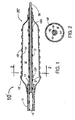
- FIG. 1 is a longitudinal cross section of an ostial stent and stent delivery catheter with the delivery balloon expanded.
- FIG. 2 is a transverse cross section at 2 - 2 from FIG. 1 for an ostial stent and stent delivery catheter with the delivery balloon expanded.
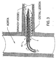
- FIG. 3 is a longitudinal cross section of an ostial stent and stent delivery catheter in place at the ostium of a blood vessel just before deployment of the ostial stent..
- FIG. 4 is a longitudinal cross section of an ostial stent and stent delivery catheter in place at the ostium of a blood vessel with the balloon expanded for deployment of the ostial stent.
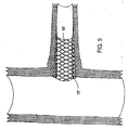
- FIG. 5 is a longitudinal cross section showing the ostial stent in place at the ostium of a blood vessel after the ostial stent has been deployed, the balloon has been deflated and the stent delivery catheter has been removed from the body.
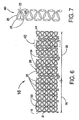
- FIG. 6 is a flat lay out view of an ostial stent design in its non-deployed state.
- FIG. 7 is a flat lay out view of a structural strut member of the ostial stent shown in FIG. 6.
- FIG. 8 is a flat lay out view of an ostial stent design in its deployed state.
- FIG. 1 is a longitudinal cross section of an ostial stent delivery system 10' comprising an ostial stent 16' and a stent delivery catheter 20' having a delivery balloon which is 14' expanded to deploy the stent 16',
- the stent delivery catheter 20' consists of an inner shaft 12, an outer shaft 11, an inflatable balloon 14' that is attached at its proximal end to the outer shaft 11 and at its distal end to the inner shaft 12.
- An annular passageway 17 that lies between the outer surface of the inner shaft 12 and the inner surface of the outer shaft 11 is in fluid communication with the annular space 18' within the balloon 14', thus allowing inflation and deflation of the balloon 14'.
- the inner shaft 12 has a central lumen 19 through which to guide wire 30 can be slideably moved. When inflated, the balloon 14' is tapered with a larger diameter at its proximal end compared to its distal end.
- a bulge 21' near the proximal end of the expanded balloon 14' provides additional expansion to further expand the most proximal strut 15' of the stent 16' to insure that the proximal strut 15' is fully embedded in the arterial wall at the ostium of the implanted vessel as is seen in FIGS. 4 and 5.
- the bulge 21' may be made of a non-compliant balloon material where there is little change in bulge diameter with balloon inflation pressure or it may be made from a compliant material where it will increase in diameter with inflation pressure to allow for further increases in expansion of the proximal strut 15'.
- the balloon 14' may be made of a non-compliant plastic which is preformed in the shape shown in FIG. 1 and then folded down over the inner catheter shaft 12.
- the stent delivery catheter 20' has a proximal radiopaque marker band 13P and a distal radiopaque marker band 13D which generally indicate the proximal and distal extremities of the stent 16' after the balloon 14' is inflated to deploy the stent 16'. It should be noted that in FIG. 1 the wires of the stent 16' are doser together for the proximal section to provide greater radial strength, and are farther apart at the distal section to allow for greater flexibility.
- FIG. 2 is a transverse cross section at 2 - 2 from FIG. 1 for the ostial stent delivery system 10' showing the expanded balloon 14' and expanded ostial stent 16'.
- FIG. 3 is a longitudinal cross section of an ostial stent delivery system 10 with stent delivery catheter 20 and non-deployed ostial stent 16 in place over the guide wire 30 at the ostium of a blood vessel just prior to deployment of the ostial stent 16 by inflation of the balloon 14.
- FIG. 4 is a longitudinal cross section of the ostial stent delivery system 10' with stent delivery catheter 20' and ostial stent 16', in place over the guide wire 30 at the ostium of a blood vessel after deployment of the ostial stent 16' by inflation of the balloon 14'.
- the balloon 14' is deflated and the stent delivery catheter 20 and guide wire 30 are removed from the body leaving the ostial stent 16', in place at the ostium of the blood vessel as is shown in FIG. 5.
- proximal strut 15' of the expanded stent 16' is expanded to a greater diameter than the rest of the stent 16' so as to reduce the probability ofthe proximal strut 15' extending proximally into the aorta.
- FIG. 5 is a longitudinal cross section showing the ostial stent 16' in place at the ostium of a blood vessel after the ostial stent 16' has been deployed, the balloon 14' has been deflated and the stent delivery catheter 20 and guide wire 30 have been removed from the body.
- FIG. 6 is a flat lay out view of an ostial stent 16 in its pre-deployment state.
- the ostial stent 16 is typically laser cut from a stainless steel tube with sets of strut members 40 comprising diagonal struts members 25 with curved ends 29 joined by the circumferential sections 23, shown in an enlarged view in FIG. 7.
- the sets of strut members 40 are the part of the stent 16 which unfold during expansion and provide the radially rigid structure which maintains vessel patency.
- the stent 16 has many sets of strut members 40 which are connected to each other with sets of either longitudinal "H” cross bars 22 or longitudinal "S" undulations 24.
- the "H" cross bars 22 are shorter in the longitudinal direction than the "S” undulations 24.
- the connected sets of strut members 40 will be closer and more rigidly connected to each other and the radial strength of that section of expanded stent will be increased at the expense of longitudinal flexibility.
- the "S" undulations interconnect the sets of strut members 40, the longitudinal flexibility of that section of stent will be increased.
- the ostial stent 16 of FIG. 6 has a proximal section 26 and distal section 28.
- the proximal section 26 is composed adjacent sets of strut members 40 having only "H" interconnections 22 to maximize the expanded radial strength.
- the distal section 28 is composed of adjacent sets of strut members 40 interconnected with only "S" undulations 24 to maximize the longitudinal flexibility.
- An alternate embodiment might have the most distal set of strut members interconnected with "H" cross bars so as to assist the normally radially weak end of the stent.
- the most proximal strut 15 with radiopaque markers 31 can be given additional expansion during stent deployment as shown in FIGS. 1, 4 and 5.
- FIG. 8 is a flat lay out view of the ostial stent 16' in its deployed state having deployed diagonal struts 25'. It should be noted here that, in the expanded state, the sets of strut members 40 are closer together and more rigidly connected with the "H" cross bars 22 in the proximal section 26 while the "S" undulations 24 do not as rigidly connect the sets of strut members 40 which are more widely spaced in the distal section 28 of the ostial stent 16'. This design increases the rigidity of the deployed proximal section 26 of the ostial stent 16 while increasing the non-deployed flexibility of the distal section 28.
- FIGS. 1 through 4 inclusive illustrate "over-the-wire" types of catheters for delivering a balloon expandable stent
- this invention of an ostial stent delivery system could also be used with a "rapid exchange” type of the stent delivery catheter in which the guide wire would exit from the stent delivery catheter near its distal end proximal to the stent location.
- a tubular sheath positioned over the stent and stent delivery catheter could be used in conjunction with this ostial stent 16 and tapered balloon delivery catheter 20.
- an ostial self-expanding stent made of a material such as Nitinol could be produced and heat treated in the shape shown in FIG. 8 then cooled and folded down to the shape in FIG. 6 for introduction into the human body.
- the materials of the stent delivery catheter system 10 are well known in the art of devices for interventional cardiology. Typically, all elastomer parts could be made from elastomers such as polyurethane, polyethylene, PTFE, FEP, or any similar plastic.
- the ostial stent 16 is ideally laser machined from a tube of metal such as stainless steel or tantalum.
- Another means to increase the relative radial strength of the proximal end of the stent is to increase the strut width of the bend 29 of the diagonal struts 25. It is also envisioned that having a stent machined from a tube having an increased wall thickness at the proximal end would provide a stent with a greater radial rigidity at its proximal end. Still further it is possible that annealing the distal half of a stent to soften the metal would increase the flexibility of the distal section.
Abstract
Description
Claims (27)
- A stent delivery catheter system for placing a stent within a vessel of a human body, the system comprising:(a) a flexible guide wire extending in a longitudinal direction;(b) a stent delivery catheter having a distal section and a proximal section, said stent delivery catheter having a longitudinally directed central lumen for slideable insertion therethrough of said flexible guidewire, said distal section of said stent delivery catheter including a deployable stent mounted on an expandable balloon having a distal section and a proximal section, said proximal section of said balloon adapted to be expanded to a larger diameter than the diameter of said distal section of said balloon upon inflation of said balloon.
- The stent delivery catheter system as recited in claim 1 where said proximal section of said balloon is formed of a non-compliant material.
- The stent delivery catheter system as recited in claim 1 where said proximal section of said balloon is formed of compliant material.
- The stent delivery catheter system as recited in claim 1 where the proximal end of said balloon proximal section includes a bulged section having a larger diameter than said after expansion of said balloon as compared with the remainder of said proximal section of said balloon.
- A stent for maintaining the patency of a vessel of the human body comprising a multiplicity of sets of strut members, adjacent sets of strut members coupled each to the other in a longitudinal extension forming a one piece stent construction, said stent having a proximal section and a distal section, said proximal section having a greater radial rigidity following deployment than said distal section.
- The stent as recited in claim 5 where said proximal section of said stent has a greater number of sets of strut members per unit length than the distal section.
- The stent as recited in claim 5 where said sets of strut members of said proximal section have an average dimensional wall thickness greater than an average dimensional wall thickness of said of sets of strut members of said distal section stent.
- The stent as recited in claim 5 where said sets of strut members of said proximal section have an average dimensional strut width greater than an average dimensional strut width of said sets of strut members of said distal section of said stent.
- The stent recited in claim 5 including a plurality of substantially linearly directed "H" cross bars connecting adjacent sets of strut members in said proximal section of said stent.
- The stent as recited in claim 5 where said stent is radially expanded responsive to inflation of a balloon onto which balloon the stent is mounted.
- The stent as recited in claim 5 where said stent is a radially self-expanding stent.
- The stent of claim 5 including at least one radiopaque marker formed on a proximal strut member of the most proximal set of strut members.
- A stent for maintaining the patency of a vessel of the human body comprising a multiplicity of sets of strut members, adjacent sets of strut members coupled each to the other in a longitudinal extension forming a one piece stent construction, said stent having a proximal section and a distal section, said distal section of said stent having a greater longitudinal flexibility prior to deployment when taken with respect to the longitudinal flexibility of said proximal section of said stent.
- The stent as recited by claim 13 where at least two adjacent located sets of said strut members are coupled each to the other by at least two substantially longitudinally extending undulating members.
- The stent as recited by claim 14 where the substantially longitudinally extending undulating members are formed in an S-shaped contour.
- The stent as recited by claim 14 where the substantially longitudinally extending undulating members are formed in a U-shaped contour.
- The stent of claim 13 including at least one radiopaque marker formed on a proximal strut member of the most proximal set of strut members.
- The stent as recited in claim 13 where said stent is radially expanded responsive to inflation of a balloon onto which balloon the stent is mounted.
- The stent as recited in claim 13 where said stent is a radially self-expanding stent.
- The stent as recited in claim 13 where said sets of strut members of said distal section have an average dimensional wall thickness smaller than an average dimensional wall thickness of said of sets of strut members of said proximal section stent.
- The stent as recited in claim 13 where said sets of strut members of said distal section have an average dimensional strut width less than the average dimensional strut width of said sets of strut members of said proximal section of said stent.
- A stent delivery catheter system for placing a stent within a vessel of a human body, the system comprising:(a) a flexible guide wire extending in a longitudinal direction;(b) a stent delivery catheter having a distal section and a proximal section, said stent delivery catheter having a longitudinally directed central lumen for slideable insertion therethrough of said flexible guidewire, said distal section of said stent delivery catheter including a deployable stent mounted on an expandable balloon having a distal section and a proximal section, said proximal section of said balloon adapted to be expanded to a larger diameter than the diameter of said distal section of said balloon upon inflation of said balloon;(c) a deployed stent for maintaining the patency of a vessel of the human body comprising a multiplicity of sets of strut members, adjacent sets of strut members coupled each to the other in a longitudinal extension forming a one piece stent construction, said deployed stent having a proximal section and a distal section, said proximal section having a greater radial rigidity than said distal section of said deployed stent.
- The stent delivery system as recited in claim 22 where said proximal section of said stent has a greater number of sets of strut members per unit length than the distal section.
- A stent delivery catheter system for placing a stent within a vessel of a human body, the system comprising:(a) a flexible guide wire extending in a longitudinal direction;(b) a stent delivery catheter having a distal section and a proximal section, said stent delivery catheter having a longitudinally directed central lumen for slideable insertion therethrough of said flexible guidewire, said distal section of said stent delivery catheter including a deployable stent mounted on an expandable balloon having a distal section and a proximal section, said proximal section of said balloon adapted to be expanded to a larger diameter than the diameter of said distal section of said balloon upon inflation of said balloon;(c) a non-deployed stent for maintaining the patency of a vessel of the human body comprising a multiplicity of sets of strut members, adjacent sets of strut members coupled each to the other in a longitudinal extension forming a one piece stent construction, said stent having a proximal section and a distal section, said distal section of said non-deployed stent having a greater longitudinal flexibility when taken with respect to the longitudinal flexibility of said proximal section of said non-deployed stent.
- The stent delivery catheter system as recited by claim 24 where the stent has at least two adjacent located sets of said strut members coupled each to the other by at least two substantially longitudinally extending undulating members.
- The stent delivery catheter system as recited by claim 24 where the stent's substantially longitudinally extending undulating members are formed in an S-shaped contour.
- The stent delivery catheter system as recited by claim 24 where the stent's substantially longitudinally extending undulating members are formed in an U-shaped contour.
Applications Claiming Priority (2)
| Application Number | Priority Date | Filing Date | Title |
|---|---|---|---|
| US85254797A | 1997-05-07 | 1997-05-07 | |
| US852547 | 1997-05-07 |
Publications (4)
| Publication Number | Publication Date |
|---|---|
| EP0876805A2 true EP0876805A2 (en) | 1998-11-11 |
| EP0876805A3 EP0876805A3 (en) | 2003-01-15 |
| EP0876805B1 EP0876805B1 (en) | 2006-08-23 |
| EP0876805B2 EP0876805B2 (en) | 2010-04-07 |
Family
ID=25313605
Family Applications (1)
| Application Number | Title | Priority Date | Filing Date |
|---|---|---|---|
| EP98303535A Expired - Lifetime EP0876805B2 (en) | 1997-05-07 | 1998-05-06 | Intravascular stent and stent delivery system for ostial vessel obstructions |
Country Status (3)
| Country | Link |
|---|---|
| EP (1) | EP0876805B2 (en) |
| AT (1) | ATE336958T1 (en) |
| DE (1) | DE69835634T3 (en) |
Cited By (38)
| Publication number | Priority date | Publication date | Assignee | Title |
|---|---|---|---|---|
| US6210429B1 (en) | 1996-11-04 | 2001-04-03 | Advanced Stent Technologies, Inc. | Extendible stent apparatus |
| US6287273B1 (en) | 1999-07-10 | 2001-09-11 | Argmed Kommanditbolag | Perfusion system |
| US6325826B1 (en) | 1998-01-14 | 2001-12-04 | Advanced Stent Technologies, Inc. | Extendible stent apparatus |
| US6682536B2 (en) | 2000-03-22 | 2004-01-27 | Advanced Stent Technologies, Inc. | Guidewire introducer sheath |
| WO2007011730A1 (en) * | 2005-07-14 | 2007-01-25 | Cappella Inc. | Delivery system and method of use for deployment of self-expandable vascular device |
| WO2007024964A1 (en) * | 2005-08-22 | 2007-03-01 | Incept, Llc | Flared stents and apparatus and methods for making and using them |
| WO2007095705A1 (en) * | 2006-02-24 | 2007-08-30 | Angiomed Importacão E Exportacão Ltda | Constructive disposition applied to balloon catheters |
| EP1905398A3 (en) * | 1998-01-14 | 2009-08-05 | Advanced Stent Technologies, Inc. | Extendible stent apparatus |
| US7654264B2 (en) | 2006-07-18 | 2010-02-02 | Nellcor Puritan Bennett Llc | Medical tube including an inflatable cuff having a notched collar |
| US7717953B2 (en) | 2004-10-13 | 2010-05-18 | Tryton Medical, Inc. | Delivery system for placement of prosthesis at luminal OS |
| US7731747B2 (en) | 2003-04-14 | 2010-06-08 | Tryton Medical, Inc. | Vascular bifurcation prosthesis with multiple thin fronds |
| US7758630B2 (en) | 2003-04-14 | 2010-07-20 | Tryton Medical, Inc. | Helical ostium support for treating vascular bifurcations |
| US7862601B2 (en) | 2005-05-23 | 2011-01-04 | Incept Llc | Apparatus and methods for delivering a stent into an ostium |
| US7972372B2 (en) | 2003-04-14 | 2011-07-05 | Tryton Medical, Inc. | Kit for treating vascular bifurcations |
| US8083791B2 (en) | 2003-04-14 | 2011-12-27 | Tryton Medical, Inc. | Method of treating a lumenal bifurcation |
| US8109987B2 (en) | 2003-04-14 | 2012-02-07 | Tryton Medical, Inc. | Method of treating a lumenal bifurcation |
| US8366763B2 (en) | 2009-07-02 | 2013-02-05 | Tryton Medical, Inc. | Ostium support for treating vascular bifurcations |
| US8740849B1 (en) | 2012-10-29 | 2014-06-03 | Ablative Solutions, Inc. | Peri-vascular tissue ablation catheter with support structures |
| US9034025B2 (en) | 2005-05-23 | 2015-05-19 | Ostial Corporation | Balloon catheters and methods for use |
| US9056185B2 (en) | 2011-08-24 | 2015-06-16 | Ablative Solutions, Inc. | Expandable catheter system for fluid injection into and deep to the wall of a blood vessel |
| US9707108B2 (en) | 2010-11-24 | 2017-07-18 | Tryton Medical, Inc. | Support for treating vascular bifurcations |
| US9795441B2 (en) | 2011-04-22 | 2017-10-24 | Ablative Solutions, Inc. | Methods of ablating tissue using a catheter injection system |
| US9839543B2 (en) | 2013-03-14 | 2017-12-12 | Cook Medical Technologies Llc | Multi-stage balloon catheter |
| US9949652B2 (en) | 2013-10-25 | 2018-04-24 | Ablative Solutions, Inc. | Apparatus for effective ablation and nerve sensing associated with denervation |
| CN108524065A (en) * | 2018-03-16 | 2018-09-14 | 上海交通大学医学院附属上海儿童医学中心 | The holder narrow applied to openings in blood vessels |
| WO2018183387A1 (en) * | 2016-03-25 | 2018-10-04 | Ostial Corporation | Balloon catheters and methods for use |
| US10350392B2 (en) | 2012-10-29 | 2019-07-16 | Ablative Solutions, Inc. | Peri-vascular tissue ablation catheter with support structures |
| US10405912B2 (en) | 2012-10-29 | 2019-09-10 | Ablative Solutions, Inc. | Transvascular methods of treating extravascular tissue |
| US10485951B2 (en) | 2011-08-24 | 2019-11-26 | Ablative Solutions, Inc. | Catheter systems and packaged kits for dual layer guide tubes |
| US10500077B2 (en) | 2012-04-26 | 2019-12-10 | Poseidon Medical Inc. | Support for treating vascular bifurcations |
| US10517666B2 (en) | 2013-10-25 | 2019-12-31 | Ablative Solutions, Inc. | Apparatus for effective ablation and nerve sensing associated with denervation |
| CN110801310A (en) * | 2019-10-21 | 2020-02-18 | 黄健兵 | Novel aortic arch part area branch tectorial membrane support type blood vessel sub-assembly |
| US10736656B2 (en) | 2012-10-29 | 2020-08-11 | Ablative Solutions | Method for painless renal denervation using a peri-vascular tissue ablation catheter with support structures |
| US10736524B2 (en) | 2013-10-25 | 2020-08-11 | Ablative Solutions, Inc. | Intravascular catheter with peri-vascular nerve activity sensors |
| US10849685B2 (en) | 2018-07-18 | 2020-12-01 | Ablative Solutions, Inc. | Peri-vascular tissue access catheter with locking handle |
| US10881458B2 (en) | 2012-10-29 | 2021-01-05 | Ablative Solutions, Inc. | Peri-vascular tissue ablation catheters |
| US10945787B2 (en) | 2012-10-29 | 2021-03-16 | Ablative Solutions, Inc. | Peri-vascular tissue ablation catheters |
| US11007346B2 (en) | 2011-04-22 | 2021-05-18 | Ablative Solutions, Inc. | Expandable catheter system for peri-ostial injection and muscle and nerve fiber ablation |
Families Citing this family (42)
| Publication number | Priority date | Publication date | Assignee | Title |
|---|---|---|---|---|
| US7341598B2 (en) | 1999-01-13 | 2008-03-11 | Boston Scientific Scimed, Inc. | Stent with protruding branch portion for bifurcated vessels |
| US8211167B2 (en) | 1999-12-06 | 2012-07-03 | Boston Scientific Scimed, Inc. | Method of using a catheter with attached flexible side sheath |
| US6599316B2 (en) | 1996-11-04 | 2003-07-29 | Advanced Stent Technologies, Inc. | Extendible stent apparatus |
| US7591846B2 (en) | 1996-11-04 | 2009-09-22 | Boston Scientific Scimed, Inc. | Methods for deploying stents in bifurcations |
| US8257425B2 (en) | 1999-01-13 | 2012-09-04 | Boston Scientific Scimed, Inc. | Stent with protruding branch portion for bifurcated vessels |
| US7655030B2 (en) | 2003-07-18 | 2010-02-02 | Boston Scientific Scimed, Inc. | Catheter balloon systems and methods |
| WO2002067653A2 (en) | 2001-02-26 | 2002-09-06 | Scimed Life Systems, Inc. | Bifurcated stent and delivery system |
| US8007528B2 (en) | 2004-03-17 | 2011-08-30 | Boston Scientific Scimed, Inc. | Bifurcated stent |
| CA2559540A1 (en) | 2004-06-08 | 2005-12-29 | Advanced Stent Technologies, Inc. | Stent with protruding branch portion for bifurcated vessels |
| US9427340B2 (en) | 2004-12-14 | 2016-08-30 | Boston Scientific Scimed, Inc. | Stent with protruding branch portion for bifurcated vessels |
| US8317855B2 (en) | 2005-05-26 | 2012-11-27 | Boston Scientific Scimed, Inc. | Crimpable and expandable side branch cell |
| US8480728B2 (en) | 2005-05-26 | 2013-07-09 | Boston Scientific Scimed, Inc. | Stent side branch deployment initiation geometry |
| US8043366B2 (en) | 2005-09-08 | 2011-10-25 | Boston Scientific Scimed, Inc. | Overlapping stent |
| US7731741B2 (en) | 2005-09-08 | 2010-06-08 | Boston Scientific Scimed, Inc. | Inflatable bifurcation stent |
| US8038706B2 (en) | 2005-09-08 | 2011-10-18 | Boston Scientific Scimed, Inc. | Crown stent assembly |
| US20070112418A1 (en) | 2005-11-14 | 2007-05-17 | Boston Scientific Scimed, Inc. | Stent with spiral side-branch support designs |
| US8343211B2 (en) | 2005-12-14 | 2013-01-01 | Boston Scientific Scimed, Inc. | Connectors for bifurcated stent |
| US8435284B2 (en) | 2005-12-14 | 2013-05-07 | Boston Scientific Scimed, Inc. | Telescoping bifurcated stent |
| US7540881B2 (en) | 2005-12-22 | 2009-06-02 | Boston Scientific Scimed, Inc. | Bifurcation stent pattern |
| US8821561B2 (en) | 2006-02-22 | 2014-09-02 | Boston Scientific Scimed, Inc. | Marker arrangement for bifurcation catheter |
| US7833264B2 (en) | 2006-03-06 | 2010-11-16 | Boston Scientific Scimed, Inc. | Bifurcated stent |
| US8298278B2 (en) | 2006-03-07 | 2012-10-30 | Boston Scientific Scimed, Inc. | Bifurcated stent with improvement securement |
| EP2051673A2 (en) | 2006-06-23 | 2009-04-29 | Boston Scientific Limited | Bifurcated stent with twisted hinges |
| US8216267B2 (en) | 2006-09-12 | 2012-07-10 | Boston Scientific Scimed, Inc. | Multilayer balloon for bifurcated stent delivery and methods of making and using the same |
| US7951191B2 (en) | 2006-10-10 | 2011-05-31 | Boston Scientific Scimed, Inc. | Bifurcated stent with entire circumferential petal |
| US8206429B2 (en) | 2006-11-02 | 2012-06-26 | Boston Scientific Scimed, Inc. | Adjustable bifurcation catheter incorporating electroactive polymer and methods of making and using the same |
| US7842082B2 (en) | 2006-11-16 | 2010-11-30 | Boston Scientific Scimed, Inc. | Bifurcated stent |
| US7959668B2 (en) | 2007-01-16 | 2011-06-14 | Boston Scientific Scimed, Inc. | Bifurcated stent |
| US8118861B2 (en) | 2007-03-28 | 2012-02-21 | Boston Scientific Scimed, Inc. | Bifurcation stent and balloon assemblies |
| US8647376B2 (en) | 2007-03-30 | 2014-02-11 | Boston Scientific Scimed, Inc. | Balloon fold design for deployment of bifurcated stent petal architecture |
| US8486134B2 (en) | 2007-08-01 | 2013-07-16 | Boston Scientific Scimed, Inc. | Bifurcation treatment system and methods |
| US7959669B2 (en) | 2007-09-12 | 2011-06-14 | Boston Scientific Scimed, Inc. | Bifurcated stent with open ended side branch support |
| US8936567B2 (en) | 2007-11-14 | 2015-01-20 | Boston Scientific Scimed, Inc. | Balloon bifurcated lumen treatment |
| US7833266B2 (en) | 2007-11-28 | 2010-11-16 | Boston Scientific Scimed, Inc. | Bifurcated stent with drug wells for specific ostial, carina, and side branch treatment |
| US8277501B2 (en) | 2007-12-21 | 2012-10-02 | Boston Scientific Scimed, Inc. | Bi-stable bifurcated stent petal geometry |
| WO2009088953A2 (en) | 2007-12-31 | 2009-07-16 | Boston Scientific Scimed Inc. | Bifurcation stent delivery system and methods |
| US8932340B2 (en) | 2008-05-29 | 2015-01-13 | Boston Scientific Scimed, Inc. | Bifurcated stent and delivery system |
| US8377108B2 (en) | 2008-06-02 | 2013-02-19 | Boston Scientific Scimed, Inc. | Staggered two balloon bifurcation catheter assembly and methods |
| JP5662310B2 (en) | 2008-06-05 | 2015-01-28 | ボストン サイエンティフィック サイムド,インコーポレイテッドBoston Scientific Scimed,Inc. | Shrinkable branch device and method of manufacturing the same |
| US9278196B2 (en) | 2011-08-24 | 2016-03-08 | Ablative Solutions, Inc. | Expandable catheter system for vessel wall injection and muscle and nerve fiber ablation |
| US9554849B2 (en) | 2012-10-29 | 2017-01-31 | Ablative Solutions, Inc. | Transvascular method of treating hypertension |
| US10226278B2 (en) | 2012-10-29 | 2019-03-12 | Ablative Solutions, Inc. | Method for painless renal denervation using a peri-vascular tissue ablation catheter with support structures |
Citations (1)
| Publication number | Priority date | Publication date | Assignee | Title |
|---|---|---|---|---|
| EP0830853A1 (en) | 1996-09-19 | 1998-03-25 | Medinol Ltd. | Stent with variable features to optimize support and method of making such stent |
Family Cites Families (12)
| Publication number | Priority date | Publication date | Assignee | Title |
|---|---|---|---|---|
| FR2683449A1 (en) † | 1991-11-08 | 1993-05-14 | Cardon Alain | ENDOPROTHESIS FOR TRANSLUMINAL IMPLANTATION. |
| US5540712A (en) * | 1992-05-01 | 1996-07-30 | Nitinol Medical Technologies, Inc. | Stent and method and apparatus for forming and delivering the same |
| US5607444A (en) * | 1993-12-02 | 1997-03-04 | Advanced Cardiovascular Systems, Inc. | Ostial stent for bifurcations |
| DE69637527D1 (en) * | 1995-03-01 | 2008-06-26 | Boston Scient Scimed Inc | Longitudinally flexible and expandable stent |
| US5632762A (en) * | 1995-11-09 | 1997-05-27 | Hemodynamics, Inc. | Ostial stent balloon |
| WO1997025937A1 (en) * | 1996-01-18 | 1997-07-24 | Jang G David | Programmable variably flexible modular stents |
| CA2248718A1 (en) * | 1996-03-05 | 1997-09-12 | Divysio Solutions Ulc. | Expandable stent and method for delivery of same |
| CA2192520A1 (en) † | 1996-03-05 | 1997-09-05 | Ian M. Penn | Expandable stent and method for delivery of same |
| NZ331269A (en) * | 1996-04-10 | 2000-01-28 | Advanced Cardiovascular System | Expandable stent, its structural strength varying along its length |
| EP0927006B1 (en) † | 1996-04-26 | 2006-01-18 | Boston Scientific Scimed, Inc. | Intravascular stent |
| US5617878A (en) * | 1996-05-31 | 1997-04-08 | Taheri; Syde A. | Stent and method for treatment of aortic occlusive disease |
| US5827321A (en) † | 1997-02-07 | 1998-10-27 | Cornerstone Devices, Inc. | Non-Foreshortening intraluminal prosthesis |
-
1998
- 1998-05-06 AT AT98303535T patent/ATE336958T1/en not_active IP Right Cessation
- 1998-05-06 EP EP98303535A patent/EP0876805B2/en not_active Expired - Lifetime
- 1998-05-06 DE DE69835634T patent/DE69835634T3/en not_active Expired - Lifetime
Patent Citations (1)
| Publication number | Priority date | Publication date | Assignee | Title |
|---|---|---|---|---|
| EP0830853A1 (en) | 1996-09-19 | 1998-03-25 | Medinol Ltd. | Stent with variable features to optimize support and method of making such stent |
Cited By (70)
| Publication number | Priority date | Publication date | Assignee | Title |
|---|---|---|---|---|
| US6210429B1 (en) | 1996-11-04 | 2001-04-03 | Advanced Stent Technologies, Inc. | Extendible stent apparatus |
| EP1905398A3 (en) * | 1998-01-14 | 2009-08-05 | Advanced Stent Technologies, Inc. | Extendible stent apparatus |
| US6325826B1 (en) | 1998-01-14 | 2001-12-04 | Advanced Stent Technologies, Inc. | Extendible stent apparatus |
| US6287273B1 (en) | 1999-07-10 | 2001-09-11 | Argmed Kommanditbolag | Perfusion system |
| US6682536B2 (en) | 2000-03-22 | 2004-01-27 | Advanced Stent Technologies, Inc. | Guidewire introducer sheath |
| US9775728B2 (en) | 2003-04-14 | 2017-10-03 | Tryton Medical, Inc. | Vascular bifurcation prosthesis |
| US8641755B2 (en) | 2003-04-14 | 2014-02-04 | Tryton Medical, Inc. | Prosthesis for treating vascular bifurcations |
| US8187314B2 (en) | 2003-04-14 | 2012-05-29 | Tryton Medical, Inc. | Prothesis and deployment catheter for treating vascular bifurcations |
| US8876884B2 (en) | 2003-04-14 | 2014-11-04 | Tryton Medical, Inc. | Prosthesis and deployment catheter for treating vascular bifurcations |
| US8672994B2 (en) | 2003-04-14 | 2014-03-18 | Tryton Medical, Inc. | Prosthesis for treating vascular bifurcations |
| US8641751B2 (en) | 2003-04-14 | 2014-02-04 | Tryton Medical, Inc. | Vascular bifurcation prosthesis with multiple linked thin fronds |
| US8109987B2 (en) | 2003-04-14 | 2012-02-07 | Tryton Medical, Inc. | Method of treating a lumenal bifurcation |
| US7731747B2 (en) | 2003-04-14 | 2010-06-08 | Tryton Medical, Inc. | Vascular bifurcation prosthesis with multiple thin fronds |
| US7758630B2 (en) | 2003-04-14 | 2010-07-20 | Tryton Medical, Inc. | Helical ostium support for treating vascular bifurcations |
| US8257432B2 (en) | 2003-04-14 | 2012-09-04 | Tryton Medical, Inc. | Vascular bifurcation prosthesis with at least one frond |
| US7972372B2 (en) | 2003-04-14 | 2011-07-05 | Tryton Medical, Inc. | Kit for treating vascular bifurcations |
| US8529618B2 (en) | 2003-04-14 | 2013-09-10 | Tryton Medical, Inc. | Ostium support for treating vascular bifurcations |
| US8083791B2 (en) | 2003-04-14 | 2011-12-27 | Tryton Medical, Inc. | Method of treating a lumenal bifurcation |
| US7972369B2 (en) | 2004-10-13 | 2011-07-05 | Tryton Medical, Inc. | Method for delivering a luminal prosthesis |
| US7717953B2 (en) | 2004-10-13 | 2010-05-18 | Tryton Medical, Inc. | Delivery system for placement of prosthesis at luminal OS |
| US8926685B2 (en) | 2004-10-13 | 2015-01-06 | Tryton Medical, Inc. | Prosthesis for placement at a luminal OS |
| US8252038B2 (en) | 2004-10-13 | 2012-08-28 | Tryton Medical, Inc. | System for delivering a prosthesis to a luminal OS |
| US9034025B2 (en) | 2005-05-23 | 2015-05-19 | Ostial Corporation | Balloon catheters and methods for use |
| US7862601B2 (en) | 2005-05-23 | 2011-01-04 | Incept Llc | Apparatus and methods for delivering a stent into an ostium |
| WO2007011730A1 (en) * | 2005-07-14 | 2007-01-25 | Cappella Inc. | Delivery system and method of use for deployment of self-expandable vascular device |
| US10092429B2 (en) | 2005-08-22 | 2018-10-09 | Incept, Llc | Flared stents and apparatus and methods for delivering them |
| US7582111B2 (en) | 2005-08-22 | 2009-09-01 | Incept, Llc | Steep-taper flared stents and apparatus and methods for delivering them |
| US8702777B2 (en) | 2005-08-22 | 2014-04-22 | Incept, Llc | Steep-taper flared stents and apparatus and methods for delivering them |
| WO2007024964A1 (en) * | 2005-08-22 | 2007-03-01 | Incept, Llc | Flared stents and apparatus and methods for making and using them |
| JP2009505742A (en) * | 2005-08-22 | 2009-02-12 | インセプト・リミテッド・ライアビリティ・カンパニー | Flare deployable stent and apparatus and method for manufacturing and using the same |
| WO2007095705A1 (en) * | 2006-02-24 | 2007-08-30 | Angiomed Importacão E Exportacão Ltda | Constructive disposition applied to balloon catheters |
| US8096299B2 (en) | 2006-07-18 | 2012-01-17 | Nellcor Puritan Bennett Llc | Medical tube including an inflatable cuff having a notched collar |
| US7654264B2 (en) | 2006-07-18 | 2010-02-02 | Nellcor Puritan Bennett Llc | Medical tube including an inflatable cuff having a notched collar |
| US9149373B2 (en) | 2009-07-02 | 2015-10-06 | Tryton Medical, Inc. | Method of treating vascular bifurcations |
| US8366763B2 (en) | 2009-07-02 | 2013-02-05 | Tryton Medical, Inc. | Ostium support for treating vascular bifurcations |
| US8382818B2 (en) | 2009-07-02 | 2013-02-26 | Tryton Medical, Inc. | Ostium support for treating vascular bifurcations |
| US10500072B2 (en) | 2010-11-24 | 2019-12-10 | Poseidon Medical Inc. | Method of treating vascular bifurcations |
| US9707108B2 (en) | 2010-11-24 | 2017-07-18 | Tryton Medical, Inc. | Support for treating vascular bifurcations |
| US11007346B2 (en) | 2011-04-22 | 2021-05-18 | Ablative Solutions, Inc. | Expandable catheter system for peri-ostial injection and muscle and nerve fiber ablation |
| US11717345B2 (en) | 2011-04-22 | 2023-08-08 | Ablative Solutions, Inc. | Methods of ablating tissue using a catheter injection system |
| US9795441B2 (en) | 2011-04-22 | 2017-10-24 | Ablative Solutions, Inc. | Methods of ablating tissue using a catheter injection system |
| US11007008B2 (en) | 2011-04-22 | 2021-05-18 | Ablative Solutions, Inc. | Methods of ablating tissue using a catheter injection system |
| US10576246B2 (en) | 2011-08-24 | 2020-03-03 | Ablative Solutions, Inc. | Intravascular fluid catheter with minimal internal fluid volume |
| US11759608B2 (en) | 2011-08-24 | 2023-09-19 | Ablative Solutions, Inc. | Intravascular fluid catheter with minimal internal fluid volume |
| US11752303B2 (en) | 2011-08-24 | 2023-09-12 | Ablative Solutions, Inc. | Catheter systems and packaged kits for dual layer guide tubes |
| US9056185B2 (en) | 2011-08-24 | 2015-06-16 | Ablative Solutions, Inc. | Expandable catheter system for fluid injection into and deep to the wall of a blood vessel |
| US11007329B2 (en) | 2011-08-24 | 2021-05-18 | Ablative Solutions, Inc. | Expandable catheter system for fluid injection into and deep to the wall of a blood vessel |
| US10485951B2 (en) | 2011-08-24 | 2019-11-26 | Ablative Solutions, Inc. | Catheter systems and packaged kits for dual layer guide tubes |
| US10500077B2 (en) | 2012-04-26 | 2019-12-10 | Poseidon Medical Inc. | Support for treating vascular bifurcations |
| US10736656B2 (en) | 2012-10-29 | 2020-08-11 | Ablative Solutions | Method for painless renal denervation using a peri-vascular tissue ablation catheter with support structures |
| US11202889B2 (en) | 2012-10-29 | 2021-12-21 | Ablative Solutions, Inc. | Peri-vascular tissue ablation catheter with support structures |
| US11944373B2 (en) | 2012-10-29 | 2024-04-02 | Ablative Solutions, Inc. | Peri-vascular tissue ablation catheters |
| US8740849B1 (en) | 2012-10-29 | 2014-06-03 | Ablative Solutions, Inc. | Peri-vascular tissue ablation catheter with support structures |
| US10350392B2 (en) | 2012-10-29 | 2019-07-16 | Ablative Solutions, Inc. | Peri-vascular tissue ablation catheter with support structures |
| US10405912B2 (en) | 2012-10-29 | 2019-09-10 | Ablative Solutions, Inc. | Transvascular methods of treating extravascular tissue |
| US10945787B2 (en) | 2012-10-29 | 2021-03-16 | Ablative Solutions, Inc. | Peri-vascular tissue ablation catheters |
| US10881458B2 (en) | 2012-10-29 | 2021-01-05 | Ablative Solutions, Inc. | Peri-vascular tissue ablation catheters |
| US9839543B2 (en) | 2013-03-14 | 2017-12-12 | Cook Medical Technologies Llc | Multi-stage balloon catheter |
| US10881312B2 (en) | 2013-10-25 | 2021-01-05 | Ablative Solutions, Inc. | Apparatus for effective ablation and nerve sensing associated with denervation |
| US11937933B2 (en) | 2013-10-25 | 2024-03-26 | Ablative Solutions, Inc. | Apparatus for effective ablation and nerve sensing associated with denervation |
| US10420481B2 (en) | 2013-10-25 | 2019-09-24 | Ablative Solutions, Inc. | Apparatus for effective ablation and nerve sensing associated with denervation |
| US10736524B2 (en) | 2013-10-25 | 2020-08-11 | Ablative Solutions, Inc. | Intravascular catheter with peri-vascular nerve activity sensors |
| US9949652B2 (en) | 2013-10-25 | 2018-04-24 | Ablative Solutions, Inc. | Apparatus for effective ablation and nerve sensing associated with denervation |
| US11510729B2 (en) | 2013-10-25 | 2022-11-29 | Ablative Solutions, Inc. | Apparatus for effective ablation and nerve sensing associated with denervation |
| US10517666B2 (en) | 2013-10-25 | 2019-12-31 | Ablative Solutions, Inc. | Apparatus for effective ablation and nerve sensing associated with denervation |
| US11751787B2 (en) | 2013-10-25 | 2023-09-12 | Ablative Solutions, Inc. | Intravascular catheter with peri-vascular nerve activity sensors |
| WO2018183387A1 (en) * | 2016-03-25 | 2018-10-04 | Ostial Corporation | Balloon catheters and methods for use |
| CN108524065A (en) * | 2018-03-16 | 2018-09-14 | 上海交通大学医学院附属上海儿童医学中心 | The holder narrow applied to openings in blood vessels |
| US10849685B2 (en) | 2018-07-18 | 2020-12-01 | Ablative Solutions, Inc. | Peri-vascular tissue access catheter with locking handle |
| CN110801310A (en) * | 2019-10-21 | 2020-02-18 | 黄健兵 | Novel aortic arch part area branch tectorial membrane support type blood vessel sub-assembly |
Also Published As
| Publication number | Publication date |
|---|---|
| EP0876805A3 (en) | 2003-01-15 |
| DE69835634D1 (en) | 2006-10-05 |
| EP0876805B1 (en) | 2006-08-23 |
| ATE336958T1 (en) | 2006-09-15 |
| EP0876805B2 (en) | 2010-04-07 |
| DE69835634T3 (en) | 2010-09-23 |
| DE69835634T2 (en) | 2007-09-13 |
Similar Documents
| Publication | Publication Date | Title |
|---|---|---|
| EP0876805B1 (en) | Intravascular stent and stent delivery system for ostial vessel obstructions | |
| US6027526A (en) | Stent having varied amounts of structural strength along its length | |
| US7799064B2 (en) | Bifurcated stent and delivery system | |
| US5913895A (en) | Intravascular stent with enhanced rigidity strut members | |
| US7758634B2 (en) | Bifurcated stent and delivery system | |
| US5593442A (en) | Radially expansible and articulated vessel scaffold | |
| US7029493B2 (en) | Stent with enhanced crossability | |
| US7037327B2 (en) | Stent with self-expanding end sections | |
| US6997946B2 (en) | Expandable stents | |
| US6409755B1 (en) | Balloon expandable stent with a self-expanding portion | |
| US6099559A (en) | Endoluminal support assembly with capped ends | |
| CA2649381C (en) | Balloon expandable stent with a self-expanding portion | |
| EP1158934B1 (en) | Stent with varying strut geometry | |
| US8221482B2 (en) | Flared ostial endoprosthesis and delivery system | |
| EP1208814A2 (en) | Low profile stent | |
| EP0870483A2 (en) | Flexible stent | |
| EP1579824A2 (en) | Variable thickness stent and method of manufacture thereof | |
| US20090259293A1 (en) | Side Branch Stent Having a Proximal Split Ring | |
| US7578840B2 (en) | Stent with reduced profile | |
| US20090259299A1 (en) | Side Branch Stent Having a Proximal Flexible Material Section | |
| AU727751B2 (en) | Stent having varied amounts of structural strength along its length | |
| AU2005227406B2 (en) | Stent with self-expanding end sections |
Legal Events
| Date | Code | Title | Description |
|---|---|---|---|
| PUAI | Public reference made under article 153(3) epc to a published international application that has entered the european phase |
Free format text: ORIGINAL CODE: 0009012 |
|
| AK | Designated contracting states |
Kind code of ref document: A2 Designated state(s): AT BE CH CY DE DK ES FI FR GB GR IE IT LI LU MC NL PT SE |
|
| AX | Request for extension of the european patent |
Free format text: AL;LT;LV;MK;RO;SI |
|
| PUAL | Search report despatched |
Free format text: ORIGINAL CODE: 0009013 |
|
| AK | Designated contracting states |
Kind code of ref document: A3 Designated state(s): AT BE CH CY DE DK ES FI FR GB GR IE IT LI LU MC NL PT SE |
|
| AX | Request for extension of the european patent |
Free format text: AL;LT;LV;MK;RO;SI |
|
| 17P | Request for examination filed |
Effective date: 20030610 |
|
| RAP1 | Party data changed (applicant data changed or rights of an application transferred) |
Owner name: CORDIS CORPORATION |
|
| RIN1 | Information on inventor provided before grant (corrected) |
Inventor name: CORDIS CORPORATION |
|
| AKX | Designation fees paid |
Designated state(s): AT BE CH CY DE DK ES LI |
|
| AXX | Extension fees paid |
Extension state: SI Payment date: 20030610 Extension state: RO Payment date: 20030610 Extension state: MK Payment date: 20030610 Extension state: LV Payment date: 20030610 Extension state: LT Payment date: 20030610 Extension state: AL Payment date: 20030610 |
|
| RIN1 | Information on inventor provided before grant (corrected) |
Inventor name: TURNLUND, TODD H. |
|
| RBV | Designated contracting states (corrected) |
Designated state(s): AT BE CH CY DE DK ES FI FR GB GR IE IT LI LU MC NL PT SE |
|
| 17Q | First examination report despatched |
Effective date: 20040923 |
|
| GRAP | Despatch of communication of intention to grant a patent |
Free format text: ORIGINAL CODE: EPIDOSNIGR1 |
|
| GRAS | Grant fee paid |
Free format text: ORIGINAL CODE: EPIDOSNIGR3 |
|
| GRAA | (expected) grant |
Free format text: ORIGINAL CODE: 0009210 |
|
| AK | Designated contracting states |
Kind code of ref document: B1 Designated state(s): AT BE CH CY DE DK ES FI FR GB GR IE IT LI LU MC NL PT SE |
|
| AX | Request for extension of the european patent |
Extension state: AL LT LV MK RO SI |
|
| PG25 | Lapsed in a contracting state [announced via postgrant information from national office to epo] |
Ref country code: LI Free format text: LAPSE BECAUSE OF FAILURE TO SUBMIT A TRANSLATION OF THE DESCRIPTION OR TO PAY THE FEE WITHIN THE PRESCRIBED TIME-LIMIT Effective date: 20060823 Ref country code: IT Free format text: LAPSE BECAUSE OF FAILURE TO SUBMIT A TRANSLATION OF THE DESCRIPTION OR TO PAY THE FEE WITHIN THE PRE;WARNING: LAPSES OF ITALIAN PATENTS WITH EFFECTIVE DATE BEFORE 2007 MAY HAVE OCCURRED AT ANY TIME BEFORE 2007. THE CORRECT EFFECTIVE DATE MAY BE DIFFERENT FROM THE ONE RECORDED.SCRIBED TIME-LIMIT Effective date: 20060823 Ref country code: FI Free format text: LAPSE BECAUSE OF FAILURE TO SUBMIT A TRANSLATION OF THE DESCRIPTION OR TO PAY THE FEE WITHIN THE PRESCRIBED TIME-LIMIT Effective date: 20060823 Ref country code: CH Free format text: LAPSE BECAUSE OF FAILURE TO SUBMIT A TRANSLATION OF THE DESCRIPTION OR TO PAY THE FEE WITHIN THE PRESCRIBED TIME-LIMIT Effective date: 20060823 Ref country code: AT Free format text: LAPSE BECAUSE OF FAILURE TO SUBMIT A TRANSLATION OF THE DESCRIPTION OR TO PAY THE FEE WITHIN THE PRESCRIBED TIME-LIMIT Effective date: 20060823 |
|
| REG | Reference to a national code |
Ref country code: GB Ref legal event code: FG4D |
|
| REG | Reference to a national code |
Ref country code: CH Ref legal event code: EP |
|
| REG | Reference to a national code |
Ref country code: IE Ref legal event code: FG4D |
|
| REF | Corresponds to: |
Ref document number: 69835634 Country of ref document: DE Date of ref document: 20061005 Kind code of ref document: P |
|
| PG25 | Lapsed in a contracting state [announced via postgrant information from national office to epo] |
Ref country code: SE Free format text: LAPSE BECAUSE OF FAILURE TO SUBMIT A TRANSLATION OF THE DESCRIPTION OR TO PAY THE FEE WITHIN THE PRESCRIBED TIME-LIMIT Effective date: 20061123 Ref country code: DK Free format text: LAPSE BECAUSE OF FAILURE TO SUBMIT A TRANSLATION OF THE DESCRIPTION OR TO PAY THE FEE WITHIN THE PRESCRIBED TIME-LIMIT Effective date: 20061123 |
|
| PG25 | Lapsed in a contracting state [announced via postgrant information from national office to epo] |
Ref country code: ES Free format text: LAPSE BECAUSE OF FAILURE TO SUBMIT A TRANSLATION OF THE DESCRIPTION OR TO PAY THE FEE WITHIN THE PRESCRIBED TIME-LIMIT Effective date: 20061204 |
|
| PG25 | Lapsed in a contracting state [announced via postgrant information from national office to epo] |
Ref country code: PT Free format text: LAPSE BECAUSE OF FAILURE TO SUBMIT A TRANSLATION OF THE DESCRIPTION OR TO PAY THE FEE WITHIN THE PRESCRIBED TIME-LIMIT Effective date: 20070124 |
|
| LTIE | Lt: invalidation of european patent or patent extension |
Effective date: 20060823 |
|
| REG | Reference to a national code |
Ref country code: CH Ref legal event code: PL |
|
| ET | Fr: translation filed | ||
| PLBI | Opposition filed |
Free format text: ORIGINAL CODE: 0009260 |
|
| PLAX | Notice of opposition and request to file observation + time limit sent |
Free format text: ORIGINAL CODE: EPIDOSNOBS2 |
|
| 26 | Opposition filed |
Opponent name: BOSTON SCIENTIFIC CORPORATION Effective date: 20070523 |
|
| NLR1 | Nl: opposition has been filed with the epo |
Opponent name: BOSTON SCIENTIFIC CORPORATION |
|
| PLAF | Information modified related to communication of a notice of opposition and request to file observations + time limit |
Free format text: ORIGINAL CODE: EPIDOSCOBS2 |
|
| PLAF | Information modified related to communication of a notice of opposition and request to file observations + time limit |
Free format text: ORIGINAL CODE: EPIDOSCOBS2 |
|
| PLBB | Reply of patent proprietor to notice(s) of opposition received |
Free format text: ORIGINAL CODE: EPIDOSNOBS3 |
|
| PG25 | Lapsed in a contracting state [announced via postgrant information from national office to epo] |
Ref country code: MC Free format text: LAPSE BECAUSE OF NON-PAYMENT OF DUE FEES Effective date: 20070531 |
|
| PG25 | Lapsed in a contracting state [announced via postgrant information from national office to epo] |
Ref country code: GR Free format text: LAPSE BECAUSE OF FAILURE TO SUBMIT A TRANSLATION OF THE DESCRIPTION OR TO PAY THE FEE WITHIN THE PRESCRIBED TIME-LIMIT Effective date: 20061124 |
|
| PLAB | Opposition data, opponent's data or that of the opponent's representative modified |
Free format text: ORIGINAL CODE: 0009299OPPO |
|
| PLAY | Examination report in opposition despatched + time limit |
Free format text: ORIGINAL CODE: EPIDOSNORE2 |
|
| PLBC | Reply to examination report in opposition received |
Free format text: ORIGINAL CODE: EPIDOSNORE3 |
|
| PG25 | Lapsed in a contracting state [announced via postgrant information from national office to epo] |
Ref country code: LU Free format text: LAPSE BECAUSE OF NON-PAYMENT OF DUE FEES Effective date: 20070506 Ref country code: CY Free format text: LAPSE BECAUSE OF FAILURE TO SUBMIT A TRANSLATION OF THE DESCRIPTION OR TO PAY THE FEE WITHIN THE PRESCRIBED TIME-LIMIT Effective date: 20060823 |
|
| PUAH | Patent maintained in amended form |
Free format text: ORIGINAL CODE: 0009272 |
|
| STAA | Information on the status of an ep patent application or granted ep patent |
Free format text: STATUS: PATENT MAINTAINED AS AMENDED |
|
| 27A | Patent maintained in amended form |
Effective date: 20100407 |
|
| AK | Designated contracting states |
Kind code of ref document: B2 Designated state(s): AT BE CH CY DE DK ES FI FR GB GR IE IT LI LU MC NL PT SE |
|
| AX | Request for extension of the european patent |
Extension state: AL LT LV MK RO SI |
|
| REG | Reference to a national code |
Ref country code: ES Ref legal event code: FD2A Effective date: 20070507 |
|
| REG | Reference to a national code |
Ref country code: NL Ref legal event code: T3 |
|
| REG | Reference to a national code |
Ref country code: FR Ref legal event code: PLFP Year of fee payment: 19 |
|
| REG | Reference to a national code |
Ref country code: FR Ref legal event code: PLFP Year of fee payment: 20 |
|
| PGFP | Annual fee paid to national office [announced via postgrant information from national office to epo] |
Ref country code: NL Payment date: 20170526 Year of fee payment: 20 |
|
| PGFP | Annual fee paid to national office [announced via postgrant information from national office to epo] |
Ref country code: IE Payment date: 20170530 Year of fee payment: 20 Ref country code: GB Payment date: 20170530 Year of fee payment: 20 Ref country code: FR Payment date: 20170525 Year of fee payment: 20 Ref country code: DE Payment date: 20170530 Year of fee payment: 20 |
|
| PGFP | Annual fee paid to national office [announced via postgrant information from national office to epo] |
Ref country code: BE Payment date: 20170529 Year of fee payment: 20 Ref country code: IT Payment date: 20170524 Year of fee payment: 20 |
|
| REG | Reference to a national code |
Ref country code: DE Ref legal event code: R071 Ref document number: 69835634 Country of ref document: DE |
|
| REG | Reference to a national code |
Ref country code: NL Ref legal event code: MK Effective date: 20180505 |
|
| REG | Reference to a national code |
Ref country code: GB Ref legal event code: PE20 Expiry date: 20180505 |
|
| REG | Reference to a national code |
Ref country code: IE Ref legal event code: MK9A |
|
| REG | Reference to a national code |
Ref country code: BE Ref legal event code: MK Effective date: 20180506 |
|
| PG25 | Lapsed in a contracting state [announced via postgrant information from national office to epo] |
Ref country code: GB Free format text: LAPSE BECAUSE OF EXPIRATION OF PROTECTION Effective date: 20180505 Ref country code: IE Free format text: LAPSE BECAUSE OF EXPIRATION OF PROTECTION Effective date: 20180506 |