EP0877327B1 - Method and apparatus for performing a join query in a database system - Google Patents
Method and apparatus for performing a join query in a database system Download PDFInfo
- Publication number
- EP0877327B1 EP0877327B1 EP98302804A EP98302804A EP0877327B1 EP 0877327 B1 EP0877327 B1 EP 0877327B1 EP 98302804 A EP98302804 A EP 98302804A EP 98302804 A EP98302804 A EP 98302804A EP 0877327 B1 EP0877327 B1 EP 0877327B1
- Authority
- EP
- European Patent Office
- Prior art keywords
- fragments
- bitmap
- join
- fragment
- query
- Prior art date
- Legal status (The legal status is an assumption and is not a legal conclusion. Google has not performed a legal analysis and makes no representation as to the accuracy of the status listed.)
- Expired - Lifetime
Links
Images


Classifications
-
- G—PHYSICS
- G06—COMPUTING; CALCULATING OR COUNTING
- G06F—ELECTRIC DIGITAL DATA PROCESSING
- G06F16/00—Information retrieval; Database structures therefor; File system structures therefor
- G06F16/20—Information retrieval; Database structures therefor; File system structures therefor of structured data, e.g. relational data
- G06F16/24—Querying
- G06F16/245—Query processing
- G06F16/2455—Query execution
- G06F16/24553—Query execution of query operations
- G06F16/24561—Intermediate data storage techniques for performance improvement
-
- G—PHYSICS
- G06—COMPUTING; CALCULATING OR COUNTING
- G06F—ELECTRIC DIGITAL DATA PROCESSING
- G06F16/00—Information retrieval; Database structures therefor; File system structures therefor
- G06F16/20—Information retrieval; Database structures therefor; File system structures therefor of structured data, e.g. relational data
- G06F16/24—Querying
- G06F16/245—Query processing
- G06F16/2455—Query execution
- G06F16/24553—Query execution of query operations
- G06F16/24558—Binary matching operations
- G06F16/2456—Join operations
-
- Y—GENERAL TAGGING OF NEW TECHNOLOGICAL DEVELOPMENTS; GENERAL TAGGING OF CROSS-SECTIONAL TECHNOLOGIES SPANNING OVER SEVERAL SECTIONS OF THE IPC; TECHNICAL SUBJECTS COVERED BY FORMER USPC CROSS-REFERENCE ART COLLECTIONS [XRACs] AND DIGESTS
- Y10—TECHNICAL SUBJECTS COVERED BY FORMER USPC
- Y10S—TECHNICAL SUBJECTS COVERED BY FORMER USPC CROSS-REFERENCE ART COLLECTIONS [XRACs] AND DIGESTS
- Y10S707/00—Data processing: database and file management or data structures
- Y10S707/99931—Database or file accessing
- Y10S707/99932—Access augmentation or optimizing
-
- Y—GENERAL TAGGING OF NEW TECHNOLOGICAL DEVELOPMENTS; GENERAL TAGGING OF CROSS-SECTIONAL TECHNOLOGIES SPANNING OVER SEVERAL SECTIONS OF THE IPC; TECHNICAL SUBJECTS COVERED BY FORMER USPC CROSS-REFERENCE ART COLLECTIONS [XRACs] AND DIGESTS
- Y10—TECHNICAL SUBJECTS COVERED BY FORMER USPC
- Y10S—TECHNICAL SUBJECTS COVERED BY FORMER USPC CROSS-REFERENCE ART COLLECTIONS [XRACs] AND DIGESTS
- Y10S707/00—Data processing: database and file management or data structures
- Y10S707/99931—Database or file accessing
- Y10S707/99933—Query processing, i.e. searching
- Y10S707/99934—Query formulation, input preparation, or translation
-
- Y—GENERAL TAGGING OF NEW TECHNOLOGICAL DEVELOPMENTS; GENERAL TAGGING OF CROSS-SECTIONAL TECHNOLOGIES SPANNING OVER SEVERAL SECTIONS OF THE IPC; TECHNICAL SUBJECTS COVERED BY FORMER USPC CROSS-REFERENCE ART COLLECTIONS [XRACs] AND DIGESTS
- Y10—TECHNICAL SUBJECTS COVERED BY FORMER USPC
- Y10S—TECHNICAL SUBJECTS COVERED BY FORMER USPC CROSS-REFERENCE ART COLLECTIONS [XRACs] AND DIGESTS
- Y10S707/00—Data processing: database and file management or data structures
- Y10S707/99931—Database or file accessing
- Y10S707/99933—Query processing, i.e. searching
- Y10S707/99935—Query augmenting and refining, e.g. inexact access
Definitions
- the present invention relates generally to database systems, and more particularly to methods and apparatus for the processing of queries having join predicates by database systems.
- a database is a collection of information.
- a relational database is typically illustrated as one or more two-dimensional tables. Each table arranges items and attributes of the items in rows and columns. Each table row corresponds to an item (referred to as a record), and each table column corresponds to an attribute of the item (referred to as a field).
- a relational database a collection of tables can be related to each other through a common attribute or "key". The common key enables information in one table to be automatically cross-referenced to corresponding information in another table.
- a complex search may be performed on a database with a "query".
- a query includes one or more predicates to specify the information for a database system to retrieve from the database.
- a join query is a query which requests information from more than one table. For example, in a database which stores customer information in one table and credit card transactions in another table, a join query may request the transactions in which customers made a purchase in the same state as their residence.
- a join query must include at least one join predicate to specify the criteria to select records from the two tables (e.g., that the state of residence of the customer be the same as the state in which the transaction occurred).
- a join query may also include one or more single-table predicates to select records from the individual tables.
- a conventional database system examines every record in the second table for each record in the first table to determine whether any records satisfy the join predicate. Such records may be said to "match.” The database system then constructs a query table from the matching records.
- the database system may apply the predicate to eliminate records from the scan of S that cannot possibly contribute to the result of the join.
- Fragmentation is another technique used to increase the processing speed of queries. Fragmentation breaks a table into horizontal sections called fragments. After fragmentation, the table consists of a collection of fragments.
- a fragment contains a set of records.
- the criteria for storing a record in a fragment is defined by the user and is known as the 'fragmentation scheme.' It is possible for a fragment to be empty if none of the records satisfy the criteria.
- a 'scan' is the process of reading a fragment of a table. Fragments may be stored independently on separate disks or on separate nodes in a cluster or network architecture. Logically, all fragments may be scanned simultaneously, thereby increasing the overall rate at which the complete table can be read. By definition, to read more than one fragment simultaneously, the database system must use multiple scan operators.
- ⁇ Fragment elimination' is a process by which the database system can identify fragments from a table that cannot participate in the result of the query and remove those fragments from consideration.
- An example of fragment elimination may be illustrated with the following query: SELECT * FROM R where R.month > "September” [ Example 2 ]
- fragment elimination allows the database system to scan three fragments instead of all twelve.
- the invention provides a method as claimed in claim 1 and corresponding system and computer program.
- join query may be performed quickly, and the performance of other similar join queries may be improved for all users on the system.
- the present invention provides a method and apparatus embodying what will be referred to as "Co-Fragment Elimination", by which a database system can optimize the processing of a join by eliminating fragments from one table using information from another table.
- the term "table” is used to denote any collection of records.
- a join in its most general form, is an operation that collects information from two or more tables. This is done by specifying one or more join predicates that combine information from records of the tables involved.
- the join predicate in the above query is f(r) relop g(s). f(r) can be as simple as R.state or something much more complex that is any function of one or more columns of R.
- join operation may be returned directly to a user or may be further processed before it is returned to a user.
- Such subsequent processing of join output may also be used for purposes of updating, inserting or deleting other data records in a database.
- present invention applies to all such activities based upon the output of a join.
- a general purpose computer system 10 runs programs enabling a user to view and perform queries on data in a database.
- the computer system 10 includes a digital computer 12 (such as a personal computer or a workstation), a display 14, a mass storage device 16 (such as a floppy-disk drive, a hard-disk drive, a CD-ROM drive, or a magneto-optical disk drive), a keyboard 18, and a mouse 20 or other pointer device (such as an input tablet).
- the computer 12 is of conventional construction and includes a memory 22, a processor 24, and other customary components, such as a memory bus and a peripheral bus (not shown).
- the computer 12 also includes communications hardware and programs (not shown) by which the computer system 10 may be connected over a communications link (not shown) to other computers (not shown) to form a computer network.
- the computer system 10 includes a database 30 for storing and processing data.
- the database 30 may be centralized on a single computer, or it may be distributed across the computer network.
- the database 30 will be managed by a database management system 38 running on a computer linked to the database, either permanently or transiently, although in this illustration the database management system is shown as running on the computer 12.
- the invention will be illustrated using a database configured to store information for a credit card company.
- the database 30 is a relational database with a customer table ("Table R") 32 and a transaction table ("Table S") 34.
- the database 30 includes a join fragment map 36 bitmap (discussed below with reference to Figures 5-6 ).
- the database 30 may also include other resources, such as rules for interacting and manipulating objects, index tables, and interpreters to execute query requests (not shown).
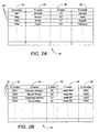
- the customer table 32 includes a record 40 for each customer.
- Each record 40 includes a customer number field (R.number) 42, a customer name field (R.name) 44, one or more customer address fields, including a customer state field (R.state) 46, and a credit card expiration month field (R.month) 48.
- the customer table 32 is partitioned into twelve fragments, one for each expiration month. Each fragment contains records only for its expiration month.
- the transaction table 34 includes a record 50 for each credit card transaction.
- Each record 50 includes a transaction number field (S.number) 52, a merchant name field (S.name) 54, a merchant state field (S.state) 56, a transaction date field (S.week) 58, and a customer number field (S.rnumber) 59.
- the customer number fields 42 and 59 may be used as keys to link Table S to Table R.
- the transaction table 34 is fragmented into fifty-two fragments, each fragment containing the records for transactions having a transaction date in one of the fifty-two weeks of the year.
- a user may submit a join query to retrieve information from the database 30.
- the user may query the database 30 to list records in which the customer state field R.state and the transaction state field S.state have the same value.
- the database system can eliminate nine fragments from Table R by applying known single-table techniques.
- the database system generates or accesses the join fragment map 36.
- the join fragment map 36 indicates which fragments from the two tables do not contain records which can satisfy the join predicate and need not be searched during the query execution.
- the join fragment map is specific both to the content of the database and the join predicate. If the content of the database changes, the join fragment map may become invalid.
- the join fragment table 36 may be stored as a bitmap, as multiple field-fragment maps, or as a fragment-fragment map or other data structure that indicates which pairs of fragments do not contain records that can satisfy the join predicate.
- the join fragment map may be composed from two field-fragment maps 60 and 70 (see Figures 3A and 3B ) for the two tables in the query.
- the join fragment map may be implemented in a database system using a relational, hierarchial, object-oriented, or non-relational database.
- the database system 30 generates or accesses a field-fragment map 70.
- the field-fragment map 70 indicates which fragments from Table S contains records from which states.
- the field-fragment map 70 includes an entry 72 for each state. Each entry 72 matches a particular state 74 to a list 76 of fragments from Table S that contain records that match the state.
- Each list 76 will contain at most fifty-two fragment numbers because there are fifty-two fragments in Table S.
- the database system 30 generates or accesses a similar field-fragment map 60 for Table R.
- the field-fragment map 60 also includes an entry 62 for each state. Each entry 62 matches a particular state 64 to a list 66 of fragments from Table R that contain records that match the particular state. There should be fifty entries 62, some of which may be empty, but each list 66 will contain at most twelve fragment numbers because there are only twelve fragments in Table R.
- the database system may determine that some records from certain fragment numbers (4, 5, 9 and 12) of Table R will match some records from certain fragment numbers (2, 4, 7, 27 and 39) of Table S. Similarly, by reading from the second row of each map, the database system may determine that records from certain fragment numbers (1, 2, 7, 9 and 11) of Table R will match records from certain fragment numbers (5, 7, 27, 30, 31 and 45) of Table S.
- the join fragment map may be composed of a single fragment-fragment map 80, formed by combining the two fragment maps 60 and 70.
- the fragment-fragment map may be created by eliminating the state columns 64 and 74 from the two field-fragment maps.
- the fragment-fragment join map 80 will contain twelve entries 82, i.e., one entry for each fragment of Table R.
- Each entry 82 will include a list 86 of fragment numbers from Table S that contain records that satisfy join predicate with records from the associated fragment 84 of Table R.
- the first entry has a list of fragments (5, 7, 27, 30, 31, 45) from Table S that contain records that satisfy the join predicate with one or more records from fragment #1 of Table R.
- the fragment-fragment map 80 was generated by combining only the first two rows of the two field-fragment maps 60 and 70.
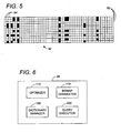
- the fragment-fragment map 80 can be transformed into a bitmap 90.
- the bitmap 90 includes a row 92 for each fragment of Table R and a column 94 for each fragment of Table S.
- an "on" bit denotes that some record in the fragment of Table S will join with the corresponding fragment of Table R.
- the bitmap 90 may be compressed, for example, by run-length encoding or other techniques.
- the bitmap 90 can be used to eliminate fragments from either table involved in the join query, as will be described in terms of the present example and the query of Example 3. Using the single-table predicate (R.month > "September"), fragments #1-#9 of Table R are eliminated. From the bitmap 90, certain remaining fragments of Table R, such as fragment #10, can be eliminated because they do not contain records that would satisfy the join predicate with records from any fragment of Table S. Similarly, the bitmap 90, shows that certain fragments of Table S do not contain records that would match records in fragments #10-#12 of Table R.
- fragments #1, #3, #6, #8-#26, #28-#29, #32-#38, #40-#44 and #46-#52 of Table S cannot contribute any records which will satisfy the join predicate. Therefore, using the bitmap 90, the database system can eliminate all but two fragments from Table R and all but nine fragments from Table S.
- the bitmap 90 is reversible. That is, fragments eliminated from Table S (based on single-table predicates) can be used, with the bitmap 90, to eliminate fragments from Table R that join only with the eliminated fragments of Table S.
- the bitmap 90 can also be used at the execution of the query to dynamically eliminate fragments. Again referring to the query of Example 3, after optimization, the database system has eliminated all but two fragments from Table R and all but nine fragments of Table S. In prior techniques, the join operator would read each record of Table R from the three fragments and scan each of the remaining nine fragments of Table S for records which satisfy the join predicate. However, for any particular record in Table R, not all nine fragments of Table S need be searched. The bitmap shows that a record from Table R fetched from fragment #11 can only find matches in six of the nine remaining fragments of Table S, namely fragments #5, #7, #27, #30, #31 and #45.
- the creation of a bitmap can be triggered in a number of ways.
- the query optimizer can decide to create the bitmap as a query processing strategy.
- a user can explicitly create a bitmap using the data definition language for a given database in similar fashion to the creation of an index.
- the database system can implicitly create a bitmap when a foreign key relationship is specified as an integrity constraint.
- the system can exhaustively search for joins between tables that yield sparse bitmaps.
- the system can use sampling to verify the expected sparseness of a resulting bitmap.
- the sparseness is the percentage of bits that are turned on in a bitmap indicating fragments from two tables that have matching tuples.
- the database system executes a 'simplified query' based on the original query.
- the simplified query contains the same join predicate as the original query, but none of the single-table predicates.
- Executing the simplified query returns the corresponding fragment numbers from each table that contain matching records.
- the bitmap 90 may be generated directly, without generating the intermediate join map 80 described above.
- Various techniques may be used to increase the speed with which the simplified query is executed.
- the necessary fields of the records from the first or second table are retrieved from the leaves of a table index rather than from the table itself.
- column indices can be used, if they exist.
- information from the fragmentation scheme may be used. Under certain implementations of the simplified query, once a match has been made between fragments from the two tables, other records need not be searched for the same match.
- bitmap may be aborted if the bitmap becomes too full, i.e., non-sparse, indicating that records from a fragment of the first table have corresponding matching records in a large percentage of the fragments from the second table.
- Sampling is used on both the first and second table for purposes of building the bitmap to arrive at an early determination of whether the bitmap will be sufficiently sparse.
- the bitmap may be stored only in volatile memory as opposed to being stored in the non-volatile metadata for a database.
- bitmap 90 There is a performance cost to building the bitmap 90. Specifically, there is a cost to executing the simplified query and storing the resulting bitmap. Therefore, the database system must decide whether the bitmap can provide a sufficient gain in performance to warrant the cost of building the bitmap. Generally, the bitmap can provide the greatest benefit if it can be used more than once, for example, in subsequent queries.
- bitmap Whenever a bitmap is created, if the bitmap is not sufficiently sparse by comparison to a system threshold, the system persistently remembers that fact in the metadata definition of a database to avoid unnecessary subsequent attempts to recreate the bitmap.
- the fragment join map may be used when the user explicitly fragments the data so as to make the map sufficiently sparse. It can also be used if the data between two tables is implicitly 'correlated' so as to result in a sufficiently sparse co-fragmentation map.
- bitmap can be used if the query uses the same join predicate but includes different single-table predicates.
- bitmaps of simple join predicates can be combined to generate the bitmap for a multiple join query.
- the bitmap for the query SELECT * FROM R,S WHERE P1 and P2 [Example 8] can be generated by a logical AND to the bitmaps for P1 and P2.
- the bitmap for the query SELECT * FROM R,S WHERE P1 or P2 [Example 9] can be generated by applying a logical OR to the bitmaps for P1 and P2.
- the database can handle multiple join predicates. For example, if the query is: SELECT R. all, S. all FROM R, S WHERE f1(r) relop1 g1(s) and/or f2(r) relop2 g2(s) and/or . . . . . . fn(r) relopn gn(s) then the database system can build one fragment join map for all the n predicates combined, or it can build n individual fragment join maps, one for each join predicate, or any intermediate combination of fragment join maps between these two extremes.
- bitmap B1 can be used to eliminate fragments from Tables R and S
- bitmap B2 can be used eliminate fragments from Tables S and T.
- bitmap B3 is constructed by combining the bitmaps B1 and B2. This technique is similar to combining join maps to construct bitmaps. Then bitmap B3 can be used to reduce R and T.
- the fragments eliminated from Table S can be used to eliminate fragments from Table R again.
- the database system would begin by using single-table fragment elimination to eliminate fragments from Tables R, S and T independently. Then bitmap B1 is used against Table R to eliminate fragments from Table S, and bitmap B2 is used against Table S to eliminate fragments in Table T. Then the database system uses the newly eliminated fragments in Table T to reduce Table S again, and then it uses the newly eliminated fragments in Table S to reduce Table R again. The database system continues to repeat this procedure until no more fragments can be eliminated from any table.
- the database system should pick the former procedure if join queries between Tables R and T are common since that procedure results in generating bitmap B3 (without explicitly building it using a "simplified bitmap query") which can be stored and used later.
- the database system should pick the latter procedure if the join queries between Tables R and T are relatively rare and do not warrant the overhead of maintaining bitmap B3.
- join fragment map is generated from the result of an actual join query, i.e., since the map depends upon the actual data in the tables, its usefulness is diminished or even destroyed when the underlying tables are modified.
- bitmap can still be used. Performance may be less than ideal as the database system may search fragments that no longer have matching records.
- the integrity of the bitmap may be destroyed. If the added or modified value now qualifies the fragment as one that contains matching records whereas prior to the update the fragment did not qualify, the integrity of the bitmap has been violated. Thus, the database system must assume that the integrity of the bitmap is violated any time that records are added or updated unless the system checks the predicate against the modified or new records.
- the system can decide to incrementally update and maintain the integrity of the bitmap. Alternately, the system can decide to invalidate the bitmap and recreate it. Such recreation of a bitmap can either be accomplished immediately, at the next instance when the bitmap is deemed necessary by the optimizer or as a result of a specific, manual command by a user.
- bitmap 90 When the integrity of the bitmap is destroyed, it needs to be restored before it can be used in future queries. As previously mentioned, there are costs to modifying bitmap 90, and there are costs to discarding and recreating it.
- the database system may estimate the time required to either modify or recreate the bitmap to select the better of the two alternatives. For example, where small incremental changes have been made to the database, it is likely that the bitmap will be modified, whereas if a large number of changes have been made in the database, the bitmap will be recreated.
- the database system includes several software subsystems including an optimizer 110, a bitmap generator 170, a dictionary manager 190, and an executor 200.
- the subsystems interact to create and use the bitmap.
- the optimizer 110 recognizes the need for a bitmap to perform co-fragment elimination, triggers an event that causes the bitmap to be built, and uses the bitmap to eliminate fragments.
- the bitmap generator 170 formulates a query to generate the bitmap, executes the simplified query and collects the fragment numbers from the result, and generates the bitmap from the collected fragment numbers.
- the dictionary manager 190 saves the bitmap in a globally accessible non-volatile storage to allow other queries and users access, and provides the bitmap to the optimizer upon request. In addition, the dictionary manager 190 marks the bitmap as invalid if data modification occurs to one or both of the underlying tables which invalidates the previous bitmap.
- the executor 200 uses the bitmap to perform dynamic co-fragment elimination during execution of the join query.
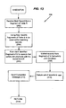
- the method 100 used by the database system to process a query from a user is shown.
- the database system optimizes the query (step 102), as discussed below with reference to the optimizer.
- the database system scans the active fragments of one of the tables (step 104). If possible, the database system should scan the fragments simultaneously.
- a join query is executed for each record received during the scan, (step 106). Once execution of the join query is complete, the processing is done.
- the optimizer performs single-table fragment elimination on both tables R and S using the single-table query predicate (step 112), as previously discussed with reference to Example 2.
- the database system determines whether or not a new bitmap should be generated (step 114).
- the user may force the database system to generate a bitmap by inserting a command or by setting a default.
- the user may allow the database system to determine whether a bitmap should be generated.
- the database system determines if the cost of building the bitmap is worth the benefits.
- the computer system estimates the length of time to run a simplified query, generate the bitmap, store the bitmap, and execute the query using the bitmap, and compare that time to an estimated length of time to perform the query without the bitmap.
- the database management system determines whether a bitmap is available for the query (step 115).
- a bitmap may be considered available only if it was generated by a join predicate that exactly matches the join predicate of the current query, and the integrity of the bitmap has not been violated.
- the optimizer calls the bitmap generator (step 116). After calling the bitmap generator to generate the bitmap, or if the bitmap was already available as determined in step 115, the optimizer fetches the bitmap (step 117), and calls a subroutine to optimize one of the tables, such as Table R (step 118).
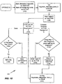
- the database system includes a method 120 for optimizing Table R.
- the database system begins by marking the fragments that were eliminated from Table R using the single-table predicates in step 112 as inactive, and marking the remaining fragments as active (step 122). Then, Table R is marked as inactive (step 124).
- the bitmap is then used to determine which fragments in Table S, if any, join with each active fragment from Table R.
- the database system enters a loop to examine each active fragment from Table R (step 128).
- the database system uses the bitmap to determine if the fragment from Table R contains any records which satisfy the join predicate with any record from any fragment from Table S (step 130). If there is no match, the fragment from Table R is marked as inactive (step 132). On the other hand, if there is a match, the fragment remains active and Table R is also marked as active (step 134). Once the last active fragment from Table R has been examined, the database system proceeds to a subroutine to optimize Table S (step 136).
- the database system includes a method 140 to optimize Table S.
- the database system begins by marking the fragments which were eliminated from Table S in step 112 as inactive, and marking the remaining fragments of Table S as active (step 142).
- the computer system sets a flag (fragment_eliminated_from_S) to "false” (step 144) and marks Table S as inactive (step 146).
- the bitmap is then used to determine which fragments in Table R, if any, join with each active fragment from Table S.
- the database system enters a loop to examine each active fragment from Table S (step 148).
- the database system uses the bitmap to determine if the fragment from Table S contains any records which satisfy the join predicate with any record from any fragment of Table R (step 152).
- the fragment from Table R is marked as inactive (step 154) and the flag is set as "true” (step 156).
- the fragment remains active and Table S is marked as active (step 158).
- the database program checks the flag (step 164). Because some fragments from Table S may have been eliminated using the bitmap, the newly eliminated fragments from Table S can be used to attempt to eliminate some of the fragments from Table R. Therefore, if the flag is set "true", the database system returns to the method 120 for optimizing Table R (step 166). Once subroutine 120 is complete, any newly eliminated fragments from Table R are used to eliminate further fragments from Table S. Thus, the database system alternates between subroutines 120 and 140 until no more fragments can be eliminated. At this point the flag will be set "false” and the database system will return to the optimizer to commence execution of the query (step 168).
- step 136 the database system returns to the optimizer rather than proceeding to the subroutine 140 to optimize Table S.
- the bitmap generator 170 begins by locking both tables to prevent the bitmap from being damaged while it is being built (step 172).
- a simplified query is then constructed (step 174).
- the simplified query contains the same join predicate as the query presented by the user, but all single-table predicates are removed.
- the simplified query is executed, and the fragment numbers from both tables are collected from the query results (step 176) to provide two field-fragment tables (e.g., fragment tables 60 and 70). Then the fragment numbers from the field-fragment tables 60 and 70 are used to construct the bitmap 90 (step 178).
- the dictionary manager subroutine 190 is called (step 180), the locks are released, and the database system returns to the optimizer (step 182).
- the dictionary manager 190 begins by determining whether a previous bitmap has been created for the join predicate of the current query (step 192). If a previous bitmap exists, then the old bitmap is discarded (step 194) and the new bitmap is saved (step 196). If there is no old bitmap for this query, then the step of discarding the previous bitmap may be skipped. Finally, the database system returns to the bitmap generator subroutine (step 198).
- executor 200 is called when the database system executes the join query in step 106 (see Figure 7 ).
- the executor receives a record from an active fragment of one of tables.
- the executor uses the fragment number and the bitmap to identify the fragments from the other table that should be scanned.
- the executor scans those fragments, collects the matching records from the fragments, and returns the matching records to the user.
- the executor begins by receiving a record from an active fragment of one Table R (step 202).
- the record is received from Table R in this example, although Tables R and S could be switched in the operations discussed below.
- the database system uses the join fragment map to identify the fragments of Table S that should be scanned for matching records (step 204).
- the database system accesses the bit at a row equal to the fragment number of Table R and a column equal to the fragment number of Table S to determine whether that pair of fragments contain records which satisfy the join predicate.
- the identified fragments of Table S are scanned for records that satisfy the join predicate (step 206). These records are collected (step 208) and returned to the user (step 210). Finally, a completion message is sent to the user (step 212) and the executor ends (step 214).
- the method of executor 200 can be carried out in a looped process in which each active fragment from Table S is examined, the bitmap is used to determine whether the fragment should be scanned, the fragment is scanned (assuming it contains matching records) and records that satisfy the join predicate are returned to the user, and the process advances to the next active fragment.
- the invention is described in terms of a software implementation, the invention may be implemented in software or hardware or firmware, or a combination of the three.
Description
- The present invention relates generally to database systems, and more particularly to methods and apparatus for the processing of queries having join predicates by database systems.
- A database is a collection of information. A relational database is typically illustrated as one or more two-dimensional tables. Each table arranges items and attributes of the items in rows and columns. Each table row corresponds to an item (referred to as a record), and each table column corresponds to an attribute of the item (referred to as a field). In a relational database a collection of tables can be related to each other through a common attribute or "key". The common key enables information in one table to be automatically cross-referenced to corresponding information in another table.
- A complex search may be performed on a database with a "query". A query includes one or more predicates to specify the information for a database system to retrieve from the database. A join query is a query which requests information from more than one table. For example, in a database which stores customer information in one table and credit card transactions in another table, a join query may request the transactions in which customers made a purchase in the same state as their residence. A join query must include at least one join predicate to specify the criteria to select records from the two tables (e.g., that the state of residence of the customer be the same as the state in which the transaction occurred). A join query may also include one or more single-table predicates to select records from the individual tables.
- To perform a join query, a conventional database system examines every record in the second table for each record in the first table to determine whether any records satisfy the join predicate. Such records may be said to "match." The database system then constructs a query table from the matching records.
- In many circumstances, conventional database operations may be unacceptably slow when performing a join query. Several techniques have been developed to reduce the time required to process join queries. One technique to improve the performance of a join query is to reduce the amount of data searched by the database system. In particular, records that cannot satisfy the join predicate should be eliminated from both tables of the query.
- An example of such a technique may be illustrated with the following query:
SELECT * FROM R, S [ Example 1]WHERE R.r = S.s and R.r < 10; - This query attempts to find all records that satisfy the join predicate R.r = S.s.
- Since records from Table R must also satisfy the predicate R.r < 10 and since R.r must equal S.s, by applying the algebraic rule of transitivity, the database system can determine that matching records of Table S must also satisfy the condition S.s < 10.
- After deducing the predicate on S, the database system may apply the predicate to eliminate records from the scan of S that cannot possibly contribute to the result of the join.
- Fragmentation is another technique used to increase the processing speed of queries. Fragmentation breaks a table into horizontal sections called fragments. After fragmentation, the table consists of a collection of fragments.
- A fragment contains a set of records. The criteria for storing a record in a fragment is defined by the user and is known as the 'fragmentation scheme.' It is possible for a fragment to be empty if none of the records satisfy the criteria.
- A 'scan' is the process of reading a fragment of a table. Fragments may be stored independently on separate disks or on separate nodes in a cluster or network architecture. Logically, all fragments may be scanned simultaneously, thereby increasing the overall rate at which the complete table can be read. By definition, to read more than one fragment simultaneously, the database system must use multiple scan operators.
- `Fragment elimination' is a process by which the database system can identify fragments from a table that cannot participate in the result of the query and remove those fragments from consideration. An example of fragment elimination may be illustrated with the following query:
SELECT * FROM R where R.month > "September" [ Example 2 ] - Assume that Table R has 12 fragments -- one for each month of the year -- and that the R.month column identifies the fragment for each record in Table R. For example,
fragment # 1 contains all records whose R.month value is "January",fragment # 2 contains all records whose R.month value is "February," and so on. - Using the query in Example 2 and the fragmentation scheme, the database system is able to eliminate all but three fragments, namely fragments #10-#12, corresponding to records whose R.month value is "October", "November" or "December". The eliminated fragments #1-#9 cannot possibly return records satisfying the query and need not be scanned. Thus, fragment elimination allows the database system to scan three fragments instead of all twelve.
- Murphy M C et al: "Processor scheduling for multiprocessor joins" Proceedings of the International Conference on Data Engineering, US, Washington, IEEE Comp. Soc. Press, vol.5, 1989, pages 140-148, XP000076112 ISBN: 0-8186-9915-9, discloses a technique for implementing database joins which uses a page connectivity graph having one node corresponding to each secondary storage page of each relation and one edge connecting each pair of pages having at least one matching join attribute, to improve the processing of the join operations.
- The invention provides a method as claimed in
claim 1 and corresponding system and computer program. - Among the advantages of the invention are the following. The join query may be performed quickly, and the performance of other similar join queries may be improved for all users on the system.
- Embodiments of the present invention will now be described, by way of example only, with reference to the accompanying drawings in which:
-
Figure 1 illustrates a general purpose computer system programmable in accordance with the invention and including a relational database. -
Figures 2A and 2B illustrate tables of the relational database ofFigure 2 . -
Figures 3A and 3B illustrate fragment maps of the tables ofFigures 3A and 3B , respectively. -
Figure 4 illustrates a join map in accordance with the present invention. -
Figure 5 illustrates a bitmap derived from the join map ofFigure 5 . -
Figure 6 illustrates the components of a database management system. -
Figure 7 is a flow diagram of the processing of a join query. -
Figures 8 ,9 , and10 are a flow diagram of a method of optimizing a join query in accordance with the present invention. -
Figures 11 and 12 are a flow diagram of a method of generating a join bitmap in accordance with the present invention. -
Figure 13 is a flow diagram of a method of executing a query in accordance with the present invention. - The present invention provides a method and apparatus embodying what will be referred to as "Co-Fragment Elimination", by which a database system can optimize the processing of a join by eliminating fragments from one table using information from another table. As used in the specification and claims, the term "table" is used to denote any collection of records.
- A join, in its most general form, is an operation that collects information from two or more tables. This is done by specifying one or more join predicates that combine information from records of the tables involved. For example, a general single predicate join between two tables R and S, can be specified by the following query:
SELECT R.all, S.all
FROM R, S
WHERE f(r) relop g(s)
where f(r) denotes any function derived from the fields of a record r of R, g(s) denotes any function derived from the fields of a record s of S, and relop is any one of (=, !=, <, <=, >, >=. The join predicate in the above query is f(r) relop g(s).
f(r) can be as simple as R.state or something much more complex that is any function of one or more columns of R. - The result of a join operation may be returned directly to a user or may be further processed before it is returned to a user. Such subsequent processing of join output may also be used for purposes of updating, inserting or deleting other data records in a database. The present invention applies to all such activities based upon the output of a join.
- Referring to
Figure 1 , a generalpurpose computer system 10 runs programs enabling a user to view and perform queries on data in a database. Thecomputer system 10 includes a digital computer 12 (such as a personal computer or a workstation), adisplay 14, a mass storage device 16 (such as a floppy-disk drive, a hard-disk drive, a CD-ROM drive, or a magneto-optical disk drive), akeyboard 18, and amouse 20 or other pointer device (such as an input tablet). Thecomputer 12 is of conventional construction and includes amemory 22, aprocessor 24, and other customary components, such as a memory bus and a peripheral bus (not shown). Thecomputer 12 also includes communications hardware and programs (not shown) by which thecomputer system 10 may be connected over a communications link (not shown) to other computers (not shown) to form a computer network. - The
computer system 10 includes adatabase 30 for storing and processing data. Thedatabase 30 may be centralized on a single computer, or it may be distributed across the computer network. Typically, thedatabase 30 will be managed by adatabase management system 38 running on a computer linked to the database, either permanently or transiently, although in this illustration the database management system is shown as running on thecomputer 12. - The invention will be illustrated using a database configured to store information for a credit card company. The
database 30 is a relational database with a customer table ("Table R") 32 and a transaction table ("Table S") 34. In addition, thedatabase 30 includes ajoin fragment map 36 bitmap (discussed below with reference toFigures 5-6 ). Thedatabase 30 may also include other resources, such as rules for interacting and manipulating objects, index tables, and interpreters to execute query requests (not shown). - Referring to
Figure 2A , the customer table 32 includes arecord 40 for each customer. Eachrecord 40 includes a customer number field (R.number) 42, a customer name field (R.name) 44, one or more customer address fields, including a customer state field (R.state) 46, and a credit card expiration month field (R.month) 48. The customer table 32 is partitioned into twelve fragments, one for each expiration month. Each fragment contains records only for its expiration month. - Referring to
Figure 2B , the transaction table 34 includes arecord 50 for each credit card transaction. Eachrecord 50 includes a transaction number field (S.number) 52, a merchant name field (S.name) 54, a merchant state field (S.state) 56, a transaction date field (S.week) 58, and a customer number field (S.rnumber) 59. Thecustomer number fields - Returning to
Figure 1 , a user (a human or a program) may submit a join query to retrieve information from thedatabase 30. For example, the user may query thedatabase 30 to list records in which the customer state field R.state and the transaction state field S.state have the same value. Now consider the following query
SELECT * FROM R, S [Example 3]WHERE R.month > "September" AND R.state = S.state - As discussed with reference to the query of Example 2, the database system can eliminate nine fragments from Table R by applying known single-table techniques.
- To eliminate other fragments, the database system generates or accesses the
join fragment map 36. Thejoin fragment map 36 indicates which fragments from the two tables do not contain records which can satisfy the join predicate and need not be searched during the query execution. Thus, the join fragment map is specific both to the content of the database and the join predicate. If the content of the database changes, the join fragment map may become invalid. The join fragment table 36 may be stored as a bitmap, as multiple field-fragment maps, or as a fragment-fragment map or other data structure that indicates which pairs of fragments do not contain records that can satisfy the join predicate. The join fragment map may be composed from two field-fragment maps 60 and 70 (seeFigures 3A and 3B ) for the two tables in the query. The join fragment map may be implemented in a database system using a relational, hierarchial, object-oriented, or non-relational database. - Referring to
Figure 3B , thedatabase system 30 generates or accesses a field-fragment map 70. The field-fragment map 70 indicates which fragments from Table S contains records from which states. The field-fragment map 70 includes anentry 72 for each state. Eachentry 72 matches aparticular state 74 to alist 76 of fragments from Table S that contain records that match the state. For example, field-fragment map 70 includes a list of fragments from Table S that contain records with S.state = "CA", a list of fragments that contain records with S.state = "AZ", and so on. Since there are fifty states, there would be fiftyentries 72, some of which may be empty, in the field-fragment map 70. Eachlist 76 will contain at most fifty-two fragment numbers because there are fifty-two fragments in Table S. - Referring to
Figure 3A , thedatabase system 30 generates or accesses a similar field-fragment map 60 for Table R. The field-fragment map 60 also includes anentry 62 for each state. Eachentry 62 matches aparticular state 64 to alist 66 of fragments from Table R that contain records that match the particular state. There should be fiftyentries 62, some of which may be empty, but eachlist 66 will contain at most twelve fragment numbers because there are only twelve fragments in Table R. - Referring to
Figures 3A and 3B , by reading the first row of the field-fragment maps - Referring to
Figure 4 , the join fragment map may be composed of a single fragment-fragment map 80, formed by combining the twofragment maps state columns fragment join map 80 will contain twelveentries 82, i.e., one entry for each fragment of Table R. Eachentry 82 will include alist 86 of fragment numbers from Table S that contain records that satisfy join predicate with records from the associatedfragment 84 of Table R. For example, the first entry has a list of fragments (5, 7, 27, 30, 31, 45) from Table S that contain records that satisfy the join predicate with one or more records fromfragment # 1 of Table R. In this illustration, the fragment-fragment map 80 was generated by combining only the first two rows of the two field-fragment maps - Referring to
Figure 5 , the fragment-fragment map 80 can be transformed into abitmap 90. Instead of a list of fragment numbers, thebitmap 90 includes arow 92 for each fragment of Table R and acolumn 94 for each fragment of Table S. In thebitmap 90, an "on" bit (shown as shaded in the Figure) denotes that some record in the fragment of Table S will join with the corresponding fragment of Table R. Thebitmap 90 may be compressed, for example, by run-length encoding or other techniques. - The
bitmap 90 can be used to eliminate fragments from either table involved in the join query, as will be described in terms of the present example and the query of Example 3. Using the single-table predicate (R.month > "September"), fragments #1-#9 of Table R are eliminated. From thebitmap 90, certain remaining fragments of Table R, such asfragment # 10, can be eliminated because they do not contain records that would satisfy the join predicate with records from any fragment of Table S. Similarly, thebitmap 90, shows that certain fragments of Table S do not contain records that would match records in fragments #10-#12 of Table R. For example, fragments #1, #3, #6, #8-#26, #28-#29, #32-#38, #40-#44 and #46-#52 of Table S cannot contribute any records which will satisfy the join predicate. Therefore, using thebitmap 90, the database system can eliminate all but two fragments from Table R and all but nine fragments from Table S. - After co-fragment elimination, the database system has to search only nine fragments of Table S for each record in the two fragments of Table R. In contrast, in the prior techniques, all fifty-two fragments of Table S would be searched for each record in three fragments of Table R. The commonly used join methods are the hash join method, the sort merge join method, and the nested loops methods. The latter may be performed with or without an index. Our invention applies to any join method. For purposes of the claims, the term "searching" does not imply the use of one particular join method.
- The
bitmap 90 is reversible. That is, fragments eliminated from Table S (based on single-table predicates) can be used, with thebitmap 90, to eliminate fragments from Table R that join only with the eliminated fragments of Table S. - The
bitmap 90 can also be used at the execution of the query to dynamically eliminate fragments. Again referring to the query of Example 3, after optimization, the database system has eliminated all but two fragments from Table R and all but nine fragments of Table S. In prior techniques, the join operator would read each record of Table R from the three fragments and scan each of the remaining nine fragments of Table S for records which satisfy the join predicate. However, for any particular record in Table R, not all nine fragments of Table S need be searched. The bitmap shows that a record from Table R fetched fromfragment # 11 can only find matches in six of the nine remaining fragments of Table S, namely fragments #5, #7, #27, #30, #31 and #45. Therefore, for this particular record from Table R, only six fragments of Table S need be scanned. Similarly, if the record fetched from Table R is fromfragment # 12, then only five fragments from Table S need be scanned, namely fragments #2, #4, #7, #27 and #39. - The creation of a bitmap can be triggered in a number of ways. The query optimizer can decide to create the bitmap as a query processing strategy. A user can explicitly create a bitmap using the data definition language for a given database in similar fashion to the creation of an index. The database system can implicitly create a bitmap when a foreign key relationship is specified as an integrity constraint. The system can exhaustively search for joins between tables that yield sparse bitmaps.
- In all of these cases, the system can use sampling to verify the expected sparseness of a resulting bitmap. The sparseness is the percentage of bits that are turned on in a bitmap indicating fragments from two tables that have matching tuples.
- To generate (or build) the
bitmap 90, the database system executes a 'simplified query' based on the original query. The simplified query contains the same join predicate as the original query, but none of the single-table predicates. For example, the simplified query for the query of Example 3 is:
SELECT R.fragment#, S.fragment# FROM R, S [Example 4]WHERE R.state = S.state - Executing the simplified query returns the corresponding fragment numbers from each table that contain matching records. The
bitmap 90 may be generated directly, without generating theintermediate join map 80 described above. Various techniques may be used to increase the speed with which the simplified query is executed. Preferably, the necessary fields of the records from the first or second table are retrieved from the leaves of a table index rather than from the table itself. In addition, column indices can be used, if they exist. As another example, information from the fragmentation scheme may be used. Under certain implementations of the simplified query, once a match has been made between fragments from the two tables, other records need not be searched for the same match. - The creation of a bitmap may be aborted if the bitmap becomes too full, i.e., non-sparse, indicating that records from a fragment of the first table have corresponding matching records in a large percentage of the fragments from the second table.
- Sampling is used on both the first and second table for purposes of building the bitmap to arrive at an early determination of whether the bitmap will be sufficiently sparse.
- The bitmap may be stored only in volatile memory as opposed to being stored in the non-volatile metadata for a database.
- There is a performance cost to building the
bitmap 90. Specifically, there is a cost to executing the simplified query and storing the resulting bitmap. Therefore, the database system must decide whether the bitmap can provide a sufficient gain in performance to warrant the cost of building the bitmap. Generally, the bitmap can provide the greatest benefit if it can be used more than once, for example, in subsequent queries. - Whenever a bitmap is created, if the bitmap is not sufficiently sparse by comparison to a system threshold, the system persistently remembers that fact in the metadata definition of a database to avoid unnecessary subsequent attempts to recreate the bitmap.
- The fragment join map may be used when the user explicitly fragments the data so as to make the map sufficiently sparse. It can also be used if the data between two tables is implicitly 'correlated' so as to result in a sufficiently sparse co-fragmentation map.
- The database system needs a
different bitmap 90 for each combination of tables, columns, and join predicates. For example, one would need separate bitmaps for the following two queries
SELECT * FROM R, S WHERE R.state = S.state [Example 5]
SELECT * FROM R, S WHERE R.state < S.state [Example 6] - However, the same bitmap can be used if the query uses the same join predicate but includes different single-table predicates.
- If the query includes multiple join predicates, then a fragment join map may be generated for each sample join in the multiple join map. For example, if the query was
SELECT * FROM R, S [Example 7]
WHERE R.state = S.state and R.name = S.name then one fragment join map would be generated using a simple query with R.state = S.state and another fragment join map would be generated using a simple query with R.name = S.name. - In addition, bitmaps of simple join predicates can be combined to generate the bitmap for a multiple join query. In this illustration predicate P1 is R.state = S.state and predicate P2 is R.name = S.name. The bitmap for the query
SELECT * FROM R,S WHERE P1 and P2 [Example 8] can be generated by a logical AND to the bitmaps for P1 and P2. Similarly, the bitmap for the query
SELECT * FROM R,S WHERE P1 or P2 [Example 9] can be generated by applying a logical OR to the bitmaps for P1 and P2. - In general, the database can handle multiple join predicates. For example, if the query is:
SELECT R. all, S. all
FROM R, S
WHERE f1(r) relop1 g1(s) and/or
f2(r) relop2 g2(s) and/or
. . .
. . .
. . .
fn(r) relopn gn(s)
then the database system can build one fragment join map for all the n predicates combined, or it can build n individual fragment join maps, one for each join predicate, or any intermediate combination of fragment join maps between these two extremes. However, if the database system builds a bitmap corresponding to two or more predicates, then that bitmap can only be used for-a query that includes the same predicates. That bitmap cannot be used if the query has a smaller number of predicates. Thus for maximum utility it might be beneficial to build one fragment join map for each single join predicate. These individual join fragment maps may be ANDed or ORed as dictated by the query.
Co-fragment elimination may also be performed on joins on three or more tables, such as
SELECT * FROM R,S,T WHERE R.a = S.a = T.a [Example 10] which is the same as the query
SELECT * FROM R,S,T WHERE R.a = S.a AND S.a = T.a
In the illustration of Example 10, B1 will be the bitmap for "R.a = S.a" and B2 will be the bitmap for "S.a = T.a". - As discussed above, bitmap B1 can be used to eliminate fragments from Tables R and S, and bitmap B2 can be used eliminate fragments from Tables S and T.
- Two techniques may be used to reduce fragments between Tables R and T. In the first technique, a bitmap B3 is constructed by combining the bitmaps B1 and B2. This technique is similar to combining join maps to construct bitmaps. Then bitmap B3 can be used to reduce R and T.
- In the second technique, the fragments eliminated from Table S (due to bitmap B2) can be used to eliminate fragments from Table R again. In general, the database system would begin by using single-table fragment elimination to eliminate fragments from Tables R, S and T independently. Then bitmap B1 is used against Table R to eliminate fragments from Table S, and bitmap B2 is used against Table S to eliminate fragments in Table T. Then the database system uses the newly eliminated fragments in Table T to reduce Table S again, and then it uses the newly eliminated fragments in Table S to reduce Table R again. The database system continues to repeat this procedure until no more fragments can be eliminated from any table.
- The database system should pick the former procedure if join queries between Tables R and T are common since that procedure results in generating bitmap B3 (without explicitly building it using a "simplified bitmap query") which can be stored and used later. On the other hand, the database system should pick the latter procedure if the join queries between Tables R and T are relatively rare and do not warrant the overhead of maintaining bitmap B3.
- Since the join fragment map is generated from the result of an actual join query, i.e., since the map depends upon the actual data in the tables, its usefulness is diminished or even destroyed when the underlying tables are modified.
- If records have been deleted from one or both tables, the bitmap can still be used. Performance may be less than ideal as the database system may search fragments that no longer have matching records.
- If records have been added or updated in one or both tables, the integrity of the bitmap may be destroyed. If the added or modified value now qualifies the fragment as one that contains matching records whereas prior to the update the fragment did not qualify, the integrity of the bitmap has been violated. Thus, the database system must assume that the integrity of the bitmap is violated any time that records are added or updated unless the system checks the predicate against the modified or new records.
- When an update occurs that would invalidate a bitmap, the system can decide to incrementally update and maintain the integrity of the bitmap. Alternately, the system can decide to invalidate the bitmap and recreate it. Such recreation of a bitmap can either be accomplished immediately, at the next instance when the bitmap is deemed necessary by the optimizer or as a result of a specific, manual command by a user.
- When the integrity of the bitmap is destroyed, it needs to be restored before it can be used in future queries. As previously mentioned, there are costs to modifying
bitmap 90, and there are costs to discarding and recreating it. The database system may estimate the time required to either modify or recreate the bitmap to select the better of the two alternatives. For example, where small incremental changes have been made to the database, it is likely that the bitmap will be modified, whereas if a large number of changes have been made in the database, the bitmap will be recreated. - Referring to
Figure 6 , the database system includes several software subsystems including anoptimizer 110, abitmap generator 170, adictionary manager 190, and anexecutor 200. The subsystems interact to create and use the bitmap. - The
optimizer 110 recognizes the need for a bitmap to perform co-fragment elimination, triggers an event that causes the bitmap to be built, and uses the bitmap to eliminate fragments. Thebitmap generator 170 formulates a query to generate the bitmap, executes the simplified query and collects the fragment numbers from the result, and generates the bitmap from the collected fragment numbers. Thedictionary manager 190 saves the bitmap in a globally accessible non-volatile storage to allow other queries and users access, and provides the bitmap to the optimizer upon request. In addition, thedictionary manager 190 marks the bitmap as invalid if data modification occurs to one or both of the underlying tables which invalidates the previous bitmap. Theexecutor 200 uses the bitmap to perform dynamic co-fragment elimination during execution of the join query. - Referring to
Figure 7 , themethod 100 used by the database system to process a query from a user is shown. First, the database system optimizes the query (step 102), as discussed below with reference to the optimizer. Then, the database system scans the active fragments of one of the tables (step 104). If possible, the database system should scan the fragments simultaneously. A join query is executed for each record received during the scan, (step 106). Once execution of the join query is complete, the processing is done. - Referring to
Figure 8 , the optimizer performs single-table fragment elimination on both tables R and S using the single-table query predicate (step 112), as previously discussed with reference to Example 2. - Then the database system determines whether or not a new bitmap should be generated (step 114). The user may force the database system to generate a bitmap by inserting a command or by setting a default. Alternatively, the user may allow the database system to determine whether a bitmap should be generated. In this cases, the database system determines if the cost of building the bitmap is worth the benefits. Specifically, using conventional techniques, the computer system estimates the length of time to run a simplified query, generate the bitmap, store the bitmap, and execute the query using the bitmap, and compare that time to an estimated length of time to perform the query without the bitmap.
- If a bitmap is needed, then the database management system determines whether a bitmap is available for the query (step 115). A bitmap may be considered available only if it was generated by a join predicate that exactly matches the join predicate of the current query, and the integrity of the bitmap has not been violated. If a bitmap is needed, then the optimizer calls the bitmap generator (step 116). After calling the bitmap generator to generate the bitmap, or if the bitmap was already available as determined in
step 115, the optimizer fetches the bitmap (step 117), and calls a subroutine to optimize one of the tables, such as Table R (step 118). - Referring to
Figure 9 , the database system includes a method 120 for optimizing Table R. The database system begins by marking the fragments that were eliminated from Table R using the single-table predicates instep 112 as inactive, and marking the remaining fragments as active (step 122). Then, Table R is marked as inactive (step 124). The bitmap is then used to determine which fragments in Table S, if any, join with each active fragment from Table R. The database system enters a loop to examine each active fragment from Table R (step 128). The database system uses the bitmap to determine if the fragment from Table R contains any records which satisfy the join predicate with any record from any fragment from Table S (step 130). If there is no match, the fragment from Table R is marked as inactive (step 132). On the other hand, if there is a match, the fragment remains active and Table R is also marked as active (step 134). Once the last active fragment from Table R has been examined, the database system proceeds to a subroutine to optimize Table S (step 136). - Referring to
Figure 10 , the database system includes amethod 140 to optimize Table S. The database system begins by marking the fragments which were eliminated from Table S instep 112 as inactive, and marking the remaining fragments of Table S as active (step 142). The computer system sets a flag (fragment_eliminated_from_S) to "false" (step 144) and marks Table S as inactive (step 146). The bitmap is then used to determine which fragments in Table R, if any, join with each active fragment from Table S. The database system enters a loop to examine each active fragment from Table S (step 148). The database system uses the bitmap to determine if the fragment from Table S contains any records which satisfy the join predicate with any record from any fragment of Table R (step 152). If there is no match, the fragment from Table R is marked as inactive (step 154) and the flag is set as "true" (step 156). On the other hand, if there is a match, the fragment remains active and Table S is marked as active (step 158). Once the fragments in both tables have been examined, if either table remains marked as inactive, then the query can halt, as it will return zero records. - Once the last active fragment from Table S has been examined, the database program checks the flag (step 164). Because some fragments from Table S may have been eliminated using the bitmap, the newly eliminated fragments from Table S can be used to attempt to eliminate some of the fragments from Table R. Therefore, if the flag is set "true", the database system returns to the method 120 for optimizing Table R (step 166). Once subroutine 120 is complete, any newly eliminated fragments from Table R are used to eliminate further fragments from Table S. Thus, the database system alternates between
subroutines 120 and 140 until no more fragments can be eliminated. At this point the flag will be set "false" and the database system will return to the optimizer to commence execution of the query (step 168). - Returning to
Figure 9 , if subroutine 120 was called fromsubroutine 140 and if no additional fragments were marked as inactive from Table R, then instep 136 the database system returns to the optimizer rather than proceeding to thesubroutine 140 to optimize Table S. - Referring to
Figure 11 , thebitmap generator 170 begins by locking both tables to prevent the bitmap from being damaged while it is being built (step 172). A simplified query is then constructed (step 174). The simplified query contains the same join predicate as the query presented by the user, but all single-table predicates are removed. The simplified query is executed, and the fragment numbers from both tables are collected from the query results (step 176) to provide two field-fragment tables (e.g., fragment tables 60 and 70). Then the fragment numbers from the field-fragment tables 60 and 70 are used to construct the bitmap 90 (step 178). Finally, thedictionary manager subroutine 190 is called (step 180), the locks are released, and the database system returns to the optimizer (step 182). - Referring to
Figure 12 , thedictionary manager 190 begins by determining whether a previous bitmap has been created for the join predicate of the current query (step 192). If a previous bitmap exists, then the old bitmap is discarded (step 194) and the new bitmap is saved (step 196). If there is no old bitmap for this query, then the step of discarding the previous bitmap may be skipped. Finally, the database system returns to the bitmap generator subroutine (step 198). - Referring to
Figure 13 ,executor 200 is called when the database system executes the join query in step 106 (seeFigure 7 ). In brief, the executor receives a record from an active fragment of one of tables. The executor uses the fragment number and the bitmap to identify the fragments from the other table that should be scanned. The executor scans those fragments, collects the matching records from the fragments, and returns the matching records to the user. The executor begins by receiving a record from an active fragment of one Table R (step 202). The record is received from Table R in this example, although Tables R and S could be switched in the operations discussed below. Then the database system uses the join fragment map to identify the fragments of Table S that should be scanned for matching records (step 204). Specifically, if the join fragment map is a bitmap, the database system accesses the bit at a row equal to the fragment number of Table R and a column equal to the fragment number of Table S to determine whether that pair of fragments contain records which satisfy the join predicate. The identified fragments of Table S are scanned for records that satisfy the join predicate (step 206). These records are collected (step 208) and returned to the user (step 210). Finally, a completion message is sent to the user (step 212) and the executor ends (step 214). - Although illustrated as a linear process, the method of
executor 200 can be carried out in a looped process in which each active fragment from Table S is examined, the bitmap is used to determine whether the fragment should be scanned, the fragment is scanned (assuming it contains matching records) and records that satisfy the join predicate are returned to the user, and the process advances to the next active fragment. - The invention is described in terms of a software implementation, the invention may be implemented in software or hardware or firmware, or a combination of the three.
- The present invention has been described in terms of an embodiment. The invention, however, is not limited to the embodiment depicted and described. Rather, the scope of the invention is defined by the appended claims.
Claims (9)
- A method for processing a join query within a data processing system having a join predicate between a first table (32) having a first plurality of fragments and a second table (34) having a second plurality of fragments, the method comprising the steps ofcreating a join fragment map (36) that, for each respective fragment from the first table, identifies the fragments from the second table which contain a record that satisfies the join predicate with a record from the respective fragment from the first table; andusing the join fragment map to process the join predicate;characterised in that the join fragment map is a bitmap (90) having a bit for each pair of fragments of the first and second table, wherein the bit of each pair of fragments from the first and second tables having records matching the join predicate is to be turned "on" wherein creating the bitmap (90) and the method comprises the steps ofdetermining by sampling the first and second tables whether or not the bit "on" population of the bitmap will be sufficiently sparsely populated that is, will have less than a given percentage of "on" bits and therefore meets selectable criteria, and that is, will have less if the "on" bit population does not meet the selectable criteria aborting the creation of the bitmap; and else turning "on" the bit of each pair of fragments from the first and second tables having records matching the join predicate.
- A method as claimed in any preceding claim, further comprising the step ofidentifying, preferably using the map, a first set of fragments from the first table which may satisfy the join predicate.
- A method as claimed in claim 2, further comprising the step ofidentifying, preferably using the map, a second set of fragments from the second table which may satisfy the join predicate with the first set of fragments.
- A method as claimed in claim 3, further comprising the step ofexecuting the query on the first set of fragments and the second set of fragments.
- A method as claimed in claim 3 or 4, further comprising the steps ofreceiving or accessing a record from the first table; andscanning the identified fragments for records that satisfy the join predicate with the received record.
- A method as claimed in any preceding claim, wherein the step of creating comprisesexecuting a simplified query having at least part of the join predicate.
- A method as claimed in any preceding claim, wherein the creation of the bitmap is triggered by a discovery process in which sparse bitmaps are located.
- A system comprising means adapted for carrying out all the steps of the method according to any preceding method claim.
- A computer program comprising instructions for carrying out all the steps of the method according to any preceding method claim, when said computer program is executed on a computer system.
Applications Claiming Priority (2)
| Application Number | Priority Date | Filing Date | Title |
|---|---|---|---|
| US08/833,519 US5987453A (en) | 1997-04-07 | 1997-04-07 | Method and apparatus for performing a join query in a database system |
| US833519 | 1997-04-07 |
Publications (3)
| Publication Number | Publication Date |
|---|---|
| EP0877327A2 EP0877327A2 (en) | 1998-11-11 |
| EP0877327A3 EP0877327A3 (en) | 2000-09-06 |
| EP0877327B1 true EP0877327B1 (en) | 2008-07-23 |
Family
ID=25264637
Family Applications (1)
| Application Number | Title | Priority Date | Filing Date |
|---|---|---|---|
| EP98302804A Expired - Lifetime EP0877327B1 (en) | 1997-04-07 | 1998-04-07 | Method and apparatus for performing a join query in a database system |
Country Status (7)
| Country | Link |
|---|---|
| US (1) | US5987453A (en) |
| EP (1) | EP0877327B1 (en) |
| JP (1) | JP4866495B2 (en) |
| AU (1) | AU752283B2 (en) |
| BR (1) | BR9804282A (en) |
| CA (1) | CA2232938C (en) |
| DE (1) | DE69839747D1 (en) |
Cited By (1)
| Publication number | Priority date | Publication date | Assignee | Title |
|---|---|---|---|---|
| US9870371B2 (en) | 2008-10-08 | 2018-01-16 | Google Llc | Associating application-specific methods with tables used for data storage |
Families Citing this family (72)
| Publication number | Priority date | Publication date | Assignee | Title |
|---|---|---|---|---|
| US6112198A (en) * | 1997-06-30 | 2000-08-29 | International Business Machines Corporation | Optimization of data repartitioning during parallel query optimization |
| JP3571201B2 (en) * | 1997-12-12 | 2004-09-29 | 富士通株式会社 | Database search device and computer-readable recording medium storing database search program |
| US6167399A (en) * | 1998-05-05 | 2000-12-26 | Ncr Corporation | Join index for relational databases |
| US6438542B1 (en) | 1999-08-30 | 2002-08-20 | International Business Machines Corporation | Method of optimally determining lossless joins |
| JP3211956B2 (en) * | 1999-08-31 | 2001-09-25 | 勲 清水 | Database system |
| US6977929B1 (en) | 1999-12-10 | 2005-12-20 | Sun Microsystems, Inc. | Method and system for facilitating relocation of devices on a network |
| US6938169B1 (en) | 1999-12-10 | 2005-08-30 | Sun Microsystems, Inc. | Channel-specific file system views in a private network using a public-network infrastructure |
| US7765581B1 (en) | 1999-12-10 | 2010-07-27 | Oracle America, Inc. | System and method for enabling scalable security in a virtual private network |
| US7336790B1 (en) * | 1999-12-10 | 2008-02-26 | Sun Microsystems Inc. | Decoupling access control from key management in a network |
| US6970941B1 (en) * | 1999-12-10 | 2005-11-29 | Sun Microsystems, Inc. | System and method for separating addresses from the delivery scheme in a virtual private network |
| AUPQ585100A0 (en) * | 2000-02-25 | 2000-03-16 | Canon Kabushiki Kaisha | Customisable filter interface |
| US6618729B1 (en) * | 2000-04-20 | 2003-09-09 | Ncr Corporation | Optimization of a star join operation using a bitmap index structure |
| US6618720B1 (en) | 2000-06-15 | 2003-09-09 | Ncr Corporation | Common spool files for maintaining join indexes |
| US6505188B1 (en) | 2000-06-15 | 2003-01-07 | Ncr Corporation | Virtual join index for relational databases |
| US6505189B1 (en) | 2000-06-15 | 2003-01-07 | Ncr Corporation | Aggregate join index for relational databases |
| US7552135B2 (en) | 2001-11-15 | 2009-06-23 | Siebel Systems, Inc. | SQL adapter business service |
| US6983275B2 (en) * | 2002-04-16 | 2006-01-03 | International Business Machines Corporation | Optimizing database query by generating, determining the type of derived predicate based on monotonicity of the column generating expression for each remaining inequality predicate in the list of unexamined predicates |
| US7765211B2 (en) * | 2003-04-29 | 2010-07-27 | International Business Machines Corporation | System and method for space management of multidimensionally clustered tables |
| US7111025B2 (en) * | 2003-04-30 | 2006-09-19 | International Business Machines Corporation | Information retrieval system and method using index ANDing for improving performance |
| US7401069B2 (en) * | 2003-09-11 | 2008-07-15 | International Business Machines Corporation | Background index bitmapping for faster query performance |
| KR20090039803A (en) * | 2003-09-15 | 2009-04-22 | 아브 이니티오 소프트웨어 엘엘시 | Data profiling |
| US7240078B2 (en) * | 2003-11-25 | 2007-07-03 | International Business Machines Corporation | Method, system, and program for query optimization with algebraic rules |
| US20050222980A1 (en) * | 2004-03-31 | 2005-10-06 | International Business Machines Corporation | Fragment elimination |
| US7596546B2 (en) * | 2004-06-14 | 2009-09-29 | Matchett Douglas K | Method and apparatus for organizing, visualizing and using measured or modeled system statistics |
| US8145642B2 (en) * | 2004-11-30 | 2012-03-27 | Oracle International Corporation | Method and apparatus to support bitmap filtering in a parallel system |
| US7536379B2 (en) * | 2004-12-15 | 2009-05-19 | International Business Machines Corporation | Performing a multiple table join operating based on generated predicates from materialized results |
| US20060235834A1 (en) * | 2005-04-14 | 2006-10-19 | Microsoft Corporation | Path expression in structured query language |
| US7428524B2 (en) * | 2005-08-05 | 2008-09-23 | Google Inc. | Large scale data storage in sparse tables |
| EP1785396A1 (en) * | 2005-11-09 | 2007-05-16 | Nederlandse Organisatie voor Toegepast-Natuuurwetenschappelijk Onderzoek TNO | Process for preparing a metal hydroxide |
| US7660814B2 (en) * | 2005-12-21 | 2010-02-09 | Teradata Us, Inc. | Techniques for mapping a physical table to multiple virtual tables |
| US7613734B2 (en) * | 2006-05-15 | 2009-11-03 | Xsprada Corporation | Systems and methods for providing data sets using a store of albegraic relations |
| US7865503B2 (en) * | 2006-05-15 | 2011-01-04 | Algebraix Data Corporation | Systems and methods for data storage and retrieval using virtual data sets |
| US7877370B2 (en) * | 2006-05-15 | 2011-01-25 | Algebraix Data Corporation | Systems and methods for data storage and retrieval using algebraic relations composed from query language statements |
| US7720806B2 (en) * | 2006-05-15 | 2010-05-18 | Algebraix Data Corporation | Systems and methods for data manipulation using multiple storage formats |
| US7797319B2 (en) * | 2006-05-15 | 2010-09-14 | Algebraix Data Corporation | Systems and methods for data model mapping |
| US7769754B2 (en) * | 2006-05-15 | 2010-08-03 | Algebraix Data Corporation | Systems and methods for data storage and retrieval using algebraic optimization |
| US7769843B2 (en) * | 2006-09-22 | 2010-08-03 | Hy Performix, Inc. | Apparatus and method for capacity planning for data center server consolidation and workload reassignment |
| US7685227B2 (en) * | 2006-11-10 | 2010-03-23 | Gerber Robert H | Message forwarding backup manager in a distributed server system |
| US8788986B2 (en) | 2010-11-22 | 2014-07-22 | Ca, Inc. | System and method for capacity planning for systems with multithreaded multicore multiprocessor resources |
| US7957948B2 (en) * | 2007-08-22 | 2011-06-07 | Hyperformit, Inc. | System and method for capacity planning for systems with multithreaded multicore multiprocessor resources |
| US8010547B2 (en) * | 2008-04-15 | 2011-08-30 | Yahoo! Inc. | Normalizing query words in web search |
| US8073840B2 (en) * | 2008-06-17 | 2011-12-06 | Attivio, Inc. | Querying joined data within a search engine index |
| CN102203773B (en) | 2008-09-19 | 2014-03-19 | 甲骨文国际公司 | Hash join using collaborative parallel filtering in intelligent storage with offloaded bloom filters |
| US8868831B2 (en) | 2009-09-14 | 2014-10-21 | Oracle International Corporation | Caching data between a database server and a storage system |
| US8438153B2 (en) * | 2010-10-11 | 2013-05-07 | Hewlett-Packard Development Company, L.P. | Performing database joins |
| AU2012211167B2 (en) | 2011-01-28 | 2014-08-21 | Ab Initio Technology Llc | Generating data pattern information |
| US9965500B2 (en) * | 2011-12-12 | 2018-05-08 | Sap Se | Mixed join of row and column database tables in native orientation |
| CN103294525A (en) | 2012-02-27 | 2013-09-11 | 国际商业机器公司 | Method and system for inquiring database with user defined function |
| US9747363B1 (en) | 2012-03-01 | 2017-08-29 | Attivio, Inc. | Efficient storage and retrieval of sparse arrays of identifier-value pairs |
| US20150033032A1 (en) * | 2012-03-29 | 2015-01-29 | Nec Corporation | Encrypted database system, client terminal, database server, data linking method and program |
| US8583687B1 (en) | 2012-05-15 | 2013-11-12 | Algebraix Data Corporation | Systems and methods for indirect algebraic partitioning |
| US8862571B2 (en) * | 2012-06-29 | 2014-10-14 | International Business Machines Corporation | Predicate pushdown with late materialization in database query processing |
| US9087209B2 (en) * | 2012-09-26 | 2015-07-21 | Protegrity Corporation | Database access control |
| CN104756107B (en) | 2012-10-22 | 2019-01-01 | 起元科技有限公司 | Using location information profile data |
| US9892026B2 (en) | 2013-02-01 | 2018-02-13 | Ab Initio Technology Llc | Data records selection |
| US20140236670A1 (en) * | 2013-02-21 | 2014-08-21 | Bank Of America Corporation | Data Communication and Analytics Platform |
| US9275103B2 (en) * | 2013-02-28 | 2016-03-01 | International Business Machines Corporation | Optimization of JOIN queries for related data |
| US10528590B2 (en) | 2014-09-26 | 2020-01-07 | Oracle International Corporation | Optimizing a query with extrema function using in-memory data summaries on the storage server |
| US10268639B2 (en) * | 2013-03-15 | 2019-04-23 | Inpixon | Joining large database tables |
| US10642837B2 (en) | 2013-03-15 | 2020-05-05 | Oracle International Corporation | Relocating derived cache during data rebalance to maintain application performance |
| US9953054B2 (en) * | 2013-04-22 | 2018-04-24 | Salesforce.Com, Inc. | Systems and methods for implementing and maintaining sampled tables in a database system |
| US11487732B2 (en) | 2014-01-16 | 2022-11-01 | Ab Initio Technology Llc | Database key identification |
| WO2015134193A1 (en) | 2014-03-07 | 2015-09-11 | Ab Initio Technology Llc | Managing data profiling operations related to data type |
| US10437824B2 (en) | 2015-01-23 | 2019-10-08 | Attivio, Inc. | Querying across a composite join of multiple database tables using a search engine index |
| US9275155B1 (en) | 2015-01-23 | 2016-03-01 | Attivio Inc. | Querying across a composite join of multiple database tables using a search engine index |
| US10977251B1 (en) * | 2015-12-30 | 2021-04-13 | Teradata Us, Inc. | Join index bitmap for non-equality query conditions |
| EP3333794A1 (en) * | 2016-12-08 | 2018-06-13 | Mastercard International Incorporated | Multi-merchant portal for e-commerce |
| US11086876B2 (en) | 2017-09-29 | 2021-08-10 | Oracle International Corporation | Storing derived summaries on persistent memory of a storage device |
| US11068540B2 (en) | 2018-01-25 | 2021-07-20 | Ab Initio Technology Llc | Techniques for integrating validation results in data profiling and related systems and methods |
| US11157478B2 (en) | 2018-12-28 | 2021-10-26 | Oracle International Corporation | Technique of comprehensively support autonomous JSON document object (AJD) cloud service |
| US11200234B2 (en) | 2019-06-14 | 2021-12-14 | Oracle International Corporation | Non-disruptive dynamic ad-hoc database catalog services |
| US10990596B2 (en) | 2019-06-14 | 2021-04-27 | Oracle International Corporation | Non-disruptive referencing of special purpose operators for database management systems |
Family Cites Families (7)
| Publication number | Priority date | Publication date | Assignee | Title |
|---|---|---|---|---|
| JPS583031A (en) * | 1981-06-30 | 1983-01-08 | Fujitsu Ltd | Join operation processing system of relational model |
| US5452238A (en) * | 1989-06-13 | 1995-09-19 | Schlumberger Technology Corporation | Method for solving geometric constraint systems |
| US5210870A (en) * | 1990-03-27 | 1993-05-11 | International Business Machines | Database sort and merge apparatus with multiple memory arrays having alternating access |
| JPH077422B2 (en) * | 1991-08-23 | 1995-01-30 | インターナショナル・ビジネス・マシーンズ・コーポレイション | Method and system for executing join in computer processing database system |
| US5412804A (en) * | 1992-04-30 | 1995-05-02 | Oracle Corporation | Extending the semantics of the outer join operator for un-nesting queries to a data base |
| EP0658260A1 (en) * | 1992-09-01 | 1995-06-21 | NUTTALL, David J. H. | Information model based on a physical system |
| CA2095311A1 (en) * | 1993-04-30 | 1994-10-31 | Richard E. Swagerman | Conversation management routine for co-operative processing applications |
-
1997
- 1997-04-07 US US08/833,519 patent/US5987453A/en not_active Expired - Lifetime
-
1998
- 1998-03-20 AU AU59437/98A patent/AU752283B2/en not_active Ceased
- 1998-03-24 CA CA002232938A patent/CA2232938C/en not_active Expired - Lifetime
- 1998-04-06 BR BR9804282-3A patent/BR9804282A/en not_active IP Right Cessation
- 1998-04-07 JP JP09482898A patent/JP4866495B2/en not_active Expired - Lifetime
- 1998-04-07 EP EP98302804A patent/EP0877327B1/en not_active Expired - Lifetime
- 1998-04-07 DE DE69839747T patent/DE69839747D1/en not_active Expired - Lifetime
Cited By (4)
| Publication number | Priority date | Publication date | Assignee | Title |
|---|---|---|---|---|
| US9870371B2 (en) | 2008-10-08 | 2018-01-16 | Google Llc | Associating application-specific methods with tables used for data storage |
| US10740301B2 (en) | 2008-10-08 | 2020-08-11 | Google Llc | Associating application-specific methods with tables used for data storage |
| US11281631B2 (en) | 2008-10-08 | 2022-03-22 | Google Llc | Associating application-specific methods with tables used for data storage |
| US11822521B2 (en) | 2008-10-08 | 2023-11-21 | Google Llc | Associating application-specific methods with tables used for data storage |
Also Published As
| Publication number | Publication date |
|---|---|
| AU5943798A (en) | 1998-10-08 |
| EP0877327A2 (en) | 1998-11-11 |
| JP4866495B2 (en) | 2012-02-01 |
| AU752283B2 (en) | 2002-09-12 |
| JPH10320423A (en) | 1998-12-04 |
| CA2232938C (en) | 2006-07-04 |
| DE69839747D1 (en) | 2008-09-04 |
| EP0877327A3 (en) | 2000-09-06 |
| US5987453A (en) | 1999-11-16 |
| MX9802587A (en) | 1998-12-31 |
| CA2232938A1 (en) | 1998-10-07 |
| BR9804282A (en) | 1999-11-16 |
Similar Documents
| Publication | Publication Date | Title |
|---|---|---|
| EP0877327B1 (en) | Method and apparatus for performing a join query in a database system | |
| US6374232B1 (en) | Method and mechanism for retrieving values from a database | |
| US6216123B1 (en) | Method and system for rapid retrieval in a full text indexing system | |
| JP2831856B2 (en) | Database access method | |
| Ozkarahan et al. | Performance evaluation of a relational associative processor | |
| US5842196A (en) | Database system with improved methods for updating records | |
| US7680784B2 (en) | Query processing system of a database using multi-operation processing utilizing a synthetic relational operation in consideration of improvement in a processing capability of a join operation | |
| US6105020A (en) | System and method for identifying and constructing star joins for execution by bitmap ANDing | |
| US7139783B2 (en) | Materialized view system and method | |
| US6343286B1 (en) | Efficient technique to defer large object access with intermediate results | |
| JP3914662B2 (en) | Database processing method and apparatus, and medium storing the processing program | |
| Hanson et al. | Selection predicate indexing for active databases using interval skip lists | |
| US6366902B1 (en) | Using an epoch number to optimize access with rowid columns and direct row access | |
| US20070250517A1 (en) | Method and Apparatus for Autonomically Maintaining Latent Auxiliary Database Structures for Use in Executing Database Queries | |
| JP4071816B1 (en) | Database query processing system using multi-operation processing using synthetic relational operations | |
| US7080072B1 (en) | Row hash match scan in a partitioned database system | |
| US8214408B2 (en) | Method, database system and computer program for joining temporal database tables | |
| US6999967B1 (en) | Semantically reducing the number of partitions involved in a join | |
| US20070130115A1 (en) | Optimizing a query that includes a large in list | |
| US7512617B2 (en) | Interval tree for identifying intervals that intersect with a query interval | |
| US20060122963A1 (en) | System and method for performing a data uniqueness check in a sorted data set | |
| US8838573B2 (en) | Autonomic index creation | |
| JP4109305B1 (en) | Database query processing system using multi-operation processing | |
| US7752612B2 (en) | Method, apparatus and program storage device for determining an optimal number of tasks during reorganization of a database system with memory and processor constraints | |
| US20020138464A1 (en) | Method and apparatus to index a historical database for efficient multiattribute SQL queries |
Legal Events
| Date | Code | Title | Description |
|---|---|---|---|
| PUAI | Public reference made under article 153(3) epc to a published international application that has entered the european phase |
Free format text: ORIGINAL CODE: 0009012 |
|
| 17P | Request for examination filed |
Effective date: 19980420 |
|
| AK | Designated contracting states |
Kind code of ref document: A2 Designated state(s): BE CH DE ES FR GB IE IT LI NL SE |
|
| AX | Request for extension of the european patent |
Free format text: AL;LT;LV;MK;RO;SI |
|
| PUAL | Search report despatched |
Free format text: ORIGINAL CODE: 0009013 |
|
| AK | Designated contracting states |
Kind code of ref document: A3 Designated state(s): AT BE CH CY DE DK ES FI FR GB GR IE IT LI LU MC NL PT SE |
|
| AX | Request for extension of the european patent |
Free format text: AL;LT;LV;MK;RO;SI |
|
| AKX | Designation fees paid |
Free format text: BE CH DE ES FR GB IE IT LI NL SE |
|
| RAP1 | Party data changed (applicant data changed or rights of an application transferred) |
Owner name: INTERNATIONAL BUSINESS MACHINES CORPORATION |
|
| 17Q | First examination report despatched |
Effective date: 20061108 |
|
| GRAP | Despatch of communication of intention to grant a patent |
Free format text: ORIGINAL CODE: EPIDOSNIGR1 |
|
| GRAS | Grant fee paid |
Free format text: ORIGINAL CODE: EPIDOSNIGR3 |
|
| GRAA | (expected) grant |
Free format text: ORIGINAL CODE: 0009210 |
|
| AK | Designated contracting states |
Kind code of ref document: B1 Designated state(s): BE CH DE ES FR GB IE IT LI NL SE |
|
| REG | Reference to a national code |
Ref country code: GB Ref legal event code: FG4D |
|
| REG | Reference to a national code |
Ref country code: CH Ref legal event code: NV Representative=s name: IBM RESEARCH GMBH ZURICH RESEARCH LABORATORY INTEL Ref country code: CH Ref legal event code: EP |
|
| REG | Reference to a national code |
Ref country code: IE Ref legal event code: FG4D |
|
| REF | Corresponds to: |
Ref document number: 69839747 Country of ref document: DE Date of ref document: 20080904 Kind code of ref document: P |
|
| NLV1 | Nl: lapsed or annulled due to failure to fulfill the requirements of art. 29p and 29m of the patents act | ||
| PG25 | Lapsed in a contracting state [announced via postgrant information from national office to epo] |
Ref country code: NL Free format text: LAPSE BECAUSE OF FAILURE TO SUBMIT A TRANSLATION OF THE DESCRIPTION OR TO PAY THE FEE WITHIN THE PRESCRIBED TIME-LIMIT Effective date: 20080723 Ref country code: ES Free format text: LAPSE BECAUSE OF FAILURE TO SUBMIT A TRANSLATION OF THE DESCRIPTION OR TO PAY THE FEE WITHIN THE PRESCRIBED TIME-LIMIT Effective date: 20081103 |
|
| PG25 | Lapsed in a contracting state [announced via postgrant information from national office to epo] |
Ref country code: BE Free format text: LAPSE BECAUSE OF FAILURE TO SUBMIT A TRANSLATION OF THE DESCRIPTION OR TO PAY THE FEE WITHIN THE PRESCRIBED TIME-LIMIT Effective date: 20080723 |
|
| REG | Reference to a national code |
Ref country code: GB Ref legal event code: 746 Effective date: 20090317 |
|
| PLBE | No opposition filed within time limit |
Free format text: ORIGINAL CODE: 0009261 |
|
| STAA | Information on the status of an ep patent application or granted ep patent |
Free format text: STATUS: NO OPPOSITION FILED WITHIN TIME LIMIT |
|
| 26N | No opposition filed |
Effective date: 20090424 |
|
| PG25 | Lapsed in a contracting state [announced via postgrant information from national office to epo] |
Ref country code: IT Free format text: LAPSE BECAUSE OF FAILURE TO SUBMIT A TRANSLATION OF THE DESCRIPTION OR TO PAY THE FEE WITHIN THE PRESCRIBED TIME-LIMIT Effective date: 20080723 |
|
| REG | Reference to a national code |
Ref country code: CH Ref legal event code: PL |
|
| PG25 | Lapsed in a contracting state [announced via postgrant information from national office to epo] |
Ref country code: SE Free format text: LAPSE BECAUSE OF FAILURE TO SUBMIT A TRANSLATION OF THE DESCRIPTION OR TO PAY THE FEE WITHIN THE PRESCRIBED TIME-LIMIT Effective date: 20081023 Ref country code: LI Free format text: LAPSE BECAUSE OF NON-PAYMENT OF DUE FEES Effective date: 20090430 Ref country code: CH Free format text: LAPSE BECAUSE OF NON-PAYMENT OF DUE FEES Effective date: 20090430 |
|
| PG25 | Lapsed in a contracting state [announced via postgrant information from national office to epo] |
Ref country code: IE Free format text: LAPSE BECAUSE OF NON-PAYMENT OF DUE FEES Effective date: 20090407 |
|
| REG | Reference to a national code |
Ref country code: DE Ref legal event code: R082 Ref document number: 69839747 Country of ref document: DE Representative=s name: MUELLER-BORE & PARTNER PATENTANWAELTE, EUROPEA, DE |
|
| REG | Reference to a national code |
Ref country code: DE Ref legal event code: R085 Ref document number: 69839747 Country of ref document: DE |
|
| REG | Reference to a national code |
Ref country code: GB Ref legal event code: 732E Free format text: REGISTERED BETWEEN 20130314 AND 20130320 |
|
| REG | Reference to a national code |
Ref country code: GB Ref legal event code: S47 Free format text: CANCELLATION OF ENTRY; APPLICATION BY FILING PATENTS FORM 15 WITHIN 4 WEEKS FROM THE DATE OF PUBLICATION OF THIS JOURNAL SAP AG METHOD AND APPARATUS FOR PERFORMING A JOIN QUERY IN A DATABASE SYSTEM APPLICATION BY PROPRIETOR TO CANCEL LICENCE OF RIGHT UNDER SECTION 47(1) FILED ON 11 JANUARY 2013 |
|
| REG | Reference to a national code |
Ref country code: DE Ref legal event code: R082 Ref document number: 69839747 Country of ref document: DE Representative=s name: MUELLER-BORE & PARTNER PATENTANWAELTE PARTG MB, DE Effective date: 20121024 Ref country code: DE Ref legal event code: R082 Ref document number: 69839747 Country of ref document: DE Representative=s name: MUELLER-BORE & PARTNER PATENTANWAELTE PARTG MB, DE Effective date: 20130425 Ref country code: DE Ref legal event code: R082 Ref document number: 69839747 Country of ref document: DE Representative=s name: MUELLER-BORE & PARTNER PATENTANWAELTE, EUROPEA, DE Effective date: 20130425 Ref country code: DE Ref legal event code: R082 Ref document number: 69839747 Country of ref document: DE Representative=s name: MUELLER-BORE & PARTNER PATENTANWAELTE, EUROPEA, DE Effective date: 20121024 Ref country code: DE Ref legal event code: R081 Ref document number: 69839747 Country of ref document: DE Owner name: SAP SE, DE Free format text: FORMER OWNER: INTERNATIONAL BUSINESS MACHINES CORPORATION, ARMONK, N.Y., US Effective date: 20130425 Ref country code: DE Ref legal event code: R081 Ref document number: 69839747 Country of ref document: DE Owner name: SAP AG, DE Free format text: FORMER OWNER: INTERNATIONAL BUSINESS MACHINES CORPORATION, ARMONK, N.Y., US Effective date: 20130425 Ref country code: DE Ref legal event code: R081 Ref document number: 69839747 Country of ref document: DE Owner name: SAP AG, DE Free format text: FORMER OWNER: INTERNATIONAL BUSINESS MACHINES CORP., ARMONK, US Effective date: 20130425 |
|
| REG | Reference to a national code |
Ref country code: GB Ref legal event code: S47 Free format text: ENTRY CANCELLED; NOTICE IS HEREBY GIVEN THAT THE ENTRY ON THE REGISTER 'LICENCES OF RIGHT' UPON THE UNDERMENTIONED PATENT WAS CANCELLED ON 10 JUNE 2013 SAP AG METHOD AND APPARATUS FOR PERFORMING A JOIN QUERY IN A DATABASE SYSTEM |
|
| REG | Reference to a national code |
Ref country code: DE Ref legal event code: R085 Ref document number: 69839747 Country of ref document: DE Effective date: 20130326 |
|
| REG | Reference to a national code |
Ref country code: DE Ref legal event code: R409 Ref document number: 69839747 Country of ref document: DE |
|
| PG25 | Lapsed in a contracting state [announced via postgrant information from national office to epo] |
Ref country code: DE Free format text: LAPSE BECAUSE OF NON-PAYMENT OF DUE FEES Effective date: 20130827 |
|
| REG | Reference to a national code |
Ref country code: DE Ref legal event code: R119 Ref document number: 69839747 Country of ref document: DE Effective date: 20130827 |
|
| REG | Reference to a national code |
Ref country code: FR Ref legal event code: TP Owner name: SAP AG, DE Effective date: 20131113 |
|
| REG | Reference to a national code |
Ref country code: DE Ref legal event code: R409 Ref document number: 69839747 Country of ref document: DE |
|
| PGRI | Patent reinstated in contracting state [announced from national office to epo] |
Ref country code: DE Effective date: 20140506 |
|
| REG | Reference to a national code |
Ref country code: DE Ref legal event code: R082 Ref document number: 69839747 Country of ref document: DE Representative=s name: MUELLER-BORE & PARTNER PATENTANWAELTE PARTG MB, DE |
|
| REG | Reference to a national code |
Ref country code: DE Ref legal event code: R082 Ref document number: 69839747 Country of ref document: DE Representative=s name: MUELLER-BORE & PARTNER PATENTANWAELTE PARTG MB, DE Effective date: 20141210 Ref country code: DE Ref legal event code: R081 Ref document number: 69839747 Country of ref document: DE Owner name: SAP SE, DE Free format text: FORMER OWNER: SAP AG, 69190 WALLDORF, DE Effective date: 20141210 |
|
| REG | Reference to a national code |
Ref country code: FR Ref legal event code: PLFP Year of fee payment: 19 |
|
| REG | Reference to a national code |
Ref country code: FR Ref legal event code: PLFP Year of fee payment: 20 |
|
| PGFP | Annual fee paid to national office [announced via postgrant information from national office to epo] |
Ref country code: DE Payment date: 20170419 Year of fee payment: 20 Ref country code: GB Payment date: 20170419 Year of fee payment: 20 Ref country code: FR Payment date: 20170419 Year of fee payment: 20 |
|
| REG | Reference to a national code |
Ref country code: DE Ref legal event code: R071 Ref document number: 69839747 Country of ref document: DE |
|
| REG | Reference to a national code |
Ref country code: GB Ref legal event code: PE20 Expiry date: 20180406 |
|
| PG25 | Lapsed in a contracting state [announced via postgrant information from national office to epo] |
Ref country code: GB Free format text: LAPSE BECAUSE OF EXPIRATION OF PROTECTION Effective date: 20180406 |